
HONEYWELL INC MINNEAPOLIS MINN SYSTEMS AND … · ad-a039 605 unclassified honeywell inc...
78
AD-A039 605 UNCLASSIFIED HONEYWELL INC MINNEAPOLIS MINN SYSTEMS AND RESEARCH —ETC F/G 11/3 EROSION RESISTANT AR COATINGS FOR IR WINOOWS.<U) FEB 77 | H DOERFFLER» H Y MAR» T SOORO F33615-76-C-5039 77S*ClS AFML-TR-77-8 NL IS PHBi^H =— • AÖ39805 ^^| HS^S Er a njgjj • E IIB • • • i • • m _.. END DATE FILMED •6^7? k.
Transcript of HONEYWELL INC MINNEAPOLIS MINN SYSTEMS AND … · ad-a039 605 unclassified honeywell inc...
AD-A039 605
UNCLASSIFIED
HONEYWELL INC MINNEAPOLIS MINN SYSTEMS AND RESEARCH —ETC F/G 11/3 EROSION RESISTANT AR COATINGS FOR IR WINOOWS.<U) FEB 77 | H DOERFFLER» H Y MAR» T SOORO F33615-76-C-5039
77S*ClS AFML-TR-77-8 NL
IS PHBi^H =—
•
AÖ39805 ^^| HS^S Er a njgjj • E IIB
• • •
i
•
• m _..
END DATE
FILMED
•6^7?
k.

1.0
I.I
28
1.25 11.4
IM 2?
2.0
1.8
1.6
Mi< R(X • * f HLSOIUIION II ' HAS
Iß © 00
.CO ©
AFML-TR-77-8
EROSION RESISTANT AR COATINGS FOR IR WINDOWS
HONEYWELL, INC. SYSTEMS AND RESEARCH CENTER 9600 RIDGWAY PARKWAY MINNEAPOLIS, MN 55*13
FEBRUARY 1977
,- G ..
TECHNICAL REPORT AFML-TR-77-8 FINAL REPORT FOR PERIOD DECEMBER 1976 - FEBRUARY 1977
Approved for public release; distribution unlimited
AIR rORCE MATERIALS LABORATORY AIR FORCE WRIGHT AERONAUTICAL LABORATORIES AIR FORCE SYSTEMS COMMAND WRIGHT-PATTERSON AIR FORCE BASE. OHIO 45433
._. _ *m

NOTICE
When Government drawings, specifications, or other data are used for any
purpose other than in connection with a definitely related Government pro-
curement operation, the United States Government thereby incurs no respon-
sibility nor any obligation whatsoever; and the fact that the government may
have formulated, furnished, or in any way supplied the said drawings, speci-
fications, or other data, is not to be regarded by implication or otherwise
as in any manner licensing the holder or any other person or coporation, or
conveying any rights or permission to manufacture, use, or sell any patented
invention that may in any way be related thereto.
dLfddadak; David W. Fischer Project Monitor
J «*
\*' **"
iO MAJUX,
William G. D. Frederick Chief Laser & Optical Materials Branch Electromagnjpic Materials Division Air Force Materials Laboratory
v »>- ;
Copies of this report should not be returned unless return is required by
security consideration, contractual obligations, or notice on a specific
document. AIR mart - % MY T? - inr»
/
UNCLASSIFIED SECURITY CLASSIFICATION OF THIS PAQE (WHEN DATA ENTERED)
AW. W. /Doerffler
EPORT DOCUMENTATION PAGE 2. GOVT ACCESSION NUMBER
«• TITLE (ANO SUBTITLE)
EROSION RESISTANT ÄRTCOATINGS
FOR Jg WINDOWS . f-
7. tuxnoMm JL
T./Boord y
H. Y. B.'Mar J./Brown ,—
—I y.
9. PERFORMING ORGANIZATIONS NAME/ADDRESS
Honeywell, Inc., Systems 4. Research Center /^T* 2fif>0 Ridcrwav Parkwav -*\j \'*J 2600 Ridgway Parkway Minneapolis, MN r,55413
11. CONTROLLING OFFICE NAME/ADDRESS Air Force Materials Laboratory (LPO) Air Force Systems Command Wright-Patterson AFB, Ohio 45433
(7$H4
READ INSTRUCTIONS BEFORE COMPLETING FORM
3. RECIPIENT'S CATALOG NUMBER
10. PROGRAM EL.EMENT.PROJECT,- •* rVgRH MagBttMJML
Project No/ 221J3 J Work Unit No. 230J 23O3Q405
BFPOBT PATf,
14. MONITORING AGENCY NAME/AOORESS (IF OIFFEREN
NUMBER OF PAGES
65 15. SECURITY CLASSIFICATION (6P IMS REPORT)
Unclassified 15«. DECLASSIFICATION DOWNGRADING SCHEDULE
16. DISTRIBUTION STATEMENT (OF THIS REPORT)
Unlimited distribution.
17. DISTRIBUTION STATEMENT (OF THE ABSTRACT ENTEREO IN BLOCK 20, IF DIFFERENT FROM REPORT« 9 \> y jT
Unlimited distribution.
11. SUPPLEMENTARY NOTES ^C S-^'o
19. KEY WORDS ( CONTINUE ON REVERSE Sl6t if NECESSARY ANÖ IDENTIFY BY BLOCK HOBWW
Antireflection coatings Two layer AR coatings Rain erosion resistant coatings ZnS, GaAs IR windows NdF,. LaF_, ThF.. ZnSe coatings
ABSTRACT (CONTINUE ON REVERSE SI DE iP NEcIiiAAV AND IDBNTIFV »V »LOCK NuMSER)
Feasibility of rain erosion resistance of two layer AR coatings on ZnS small sample windows with good surface finish has been demonstrated. When exposed to 1 inch/hour simulated rainfalls for 20 minutes at a relative drop impact velocity of 470 mph, trans- mission losses of about 10 percent occurred,
DO, FORM JAN 7} 1473 EDITION OF I NOV 55 IS OBSOLETE
UNCLASSIFIED SECURITY CLASSIFICATION OF THIS PAGE (WHEN DATA ENTERED)
f) , 5T 7 1WT -*»-'—•

* N
UNCLASSIFIED _______ S-CURITV CLASSIFICATION OF rHIS PAOE (WHEN OATA ENTERED)
The same coating combinations (ZnSe/NdFg, ZnSe/LaF3 and ZnSe/ThF4) exhibited severe degradation after rain erosion testing when prepared on GaAs windows. The surface finish of the substrate windows appears to be an important factor for rain erosion resistance of coatings. ZnS and GaAs which did not meet the scratch and dig requirement of 60/40 exhibited poor rain erosion resistance of coatings. ZnS windows which exceeded the 60/40 requirement (close to 40/20) exhibited superior rain erosion resistance of deposited coatings.
SECURITY CLASSIFICATION OF THIS PAOE (WHEN DATA ENTEREDI

PREFACE
This is the final technical report to the Air Force Materials Laboratory for
the project to develop erosion resistant AR coatings for IR windows. This
work was performed under Air Force Contract No. F33615-76-C-5039.
Mr. D. W. Fischer, AFML/LPO, was the project monitor. Mr. T. L.
Peterson, AFML/MBE, conducted the rain erosion testing.
This project was performed at Honeywell Inc., Systems and Research
Center, 2600 Ridgway Parkway, Minneapolis, MN 55413. Dr. W. W.
Doerffler was the principal investigator. The coatings design and computer
analysis was performed by Dr. W. T. Boord and Mr. R. K. Daggit.
Mr. J. L. Brown was responsible for the coatings preparation and testing.
The MTF measurements and related analysis were performed by Mr. R. E.
Zirkle, Mr. E. Bernal (Honeywell Corporate Research Center) and
Mr. A. J. Mundy.
Routine MTF measurements were performed at Honeywell's Radiation
Center (Lexington, MA).
'

TABLE OF CONTENTS
Section
I INTRODUCTION AND SUMMARY . . .
Page
1
II CONCLUSIONS
III RECOMMENDATIONS
IV COATINGS PERFORMANCE GOALS
I
VI
vn
VIII
DC
IR WINDOW MATERIALS 8
Zinc Sulfide 8
Gallium Arsenide 13
ANTIREFLECTION COATING DESIGNS 17
COATINGS FABRICATION 31
OPTIMIZATION OF FABRICATION PROCESS AND COATINGS DESIGN 33
OPTICAL PERFORMANCE OF COATED WINDOWS VERSUS DESIGN OR PERFORMANCE GOALS 41
Zinc Sulfide Windows 42
Gallium Arsenide Windows 42
iii i PRSCKDINO PAQ£|ßLANK-NOT FUMED
TABLE OF CONTENTS (concluded)
Section Page
X RAIN EROSION TEST DATA 43
XI VALIDATING MEASUREMENTS 51
APPENDIX—FABRICATION PROCESS OF EROSION RESISTANT AR COATINGS FOR IR WINDOWS 52
iv

I
LIST OF ILLUSTRATIONS
Figure
1
Page
4
5
6
7
8
9
10
11
12
13
Representative Surface Area of ZnS Window as Received, Which Does Not Meet 60/40 Scratch and Dig Requirement
Representative Surface Area of ZnS Window as Received, Which Exceeds 60/40 Scratch and Dig Requirement
Short Wavelength Absorption Edge of ZnS Window as Received
Transmission of ZnS Substrate without Coatings . .
Representative Surface Area of GaAs Window as Received Which Does Not Meet 60/40 Scratch and Dig Requirement
Transmission of GaAs Substrate without Coating . .
Transmission Spectrum of GaAs without Coatings . .
Calculated Transmission of a GaAs Surface with a Single Layer AR Coating
Schuster Diagram for Double Layer AR Coatings on GaAs
Schuster Diagram for Double Layer AR Coatings on ZnS
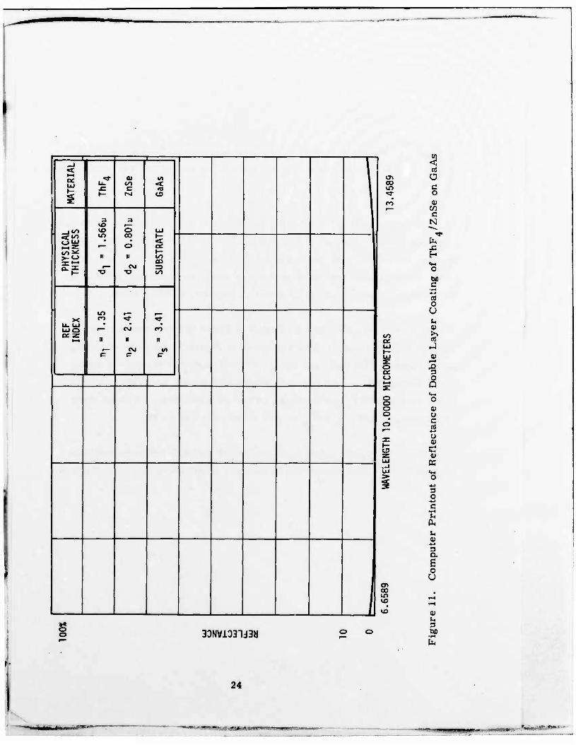
Computed Reflectance of Double Layer Coating of ThF./ZnSe on GaAs 4
Computed Reflectance of Double Layer Coating of NdF_/ZnSe on GaAs
Computed Reflectance of Double Layer Coating of ThFjNdF„ on ZnS 4 3
v
10
11
12
14
15
16
18
19
21
24
25
26
4—m

LIST OF ILLUSTRATIONS (concluded)
Figure Page
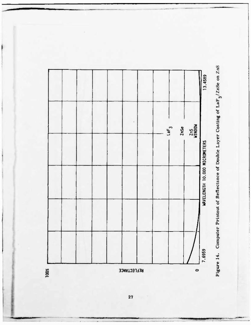
14 Computed Reflectance of Double Layer Coating of LaF3/ZnSe on ZnS 27
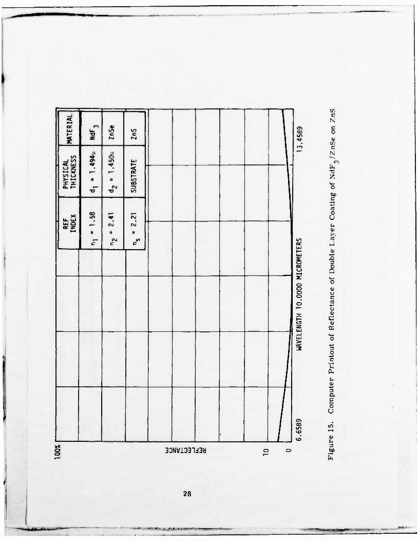
15 Computed Reflectance of Double Layer Coating of NdFg/ZnSe on ZnS 28
16 Computed Reflectance of Three Layer Coating of LaF3/Si/LaF3 on ZnS 29
17 Transmission of Coated ZnS Windows between 0. 5 and 2. 5 pin 35
18 Transmission and Reflectance of Coated ZnS (ZnSe/ NdF„) Before and After Post-Annealing 36
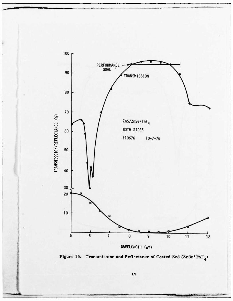
19 Transmission and Reflectance of Coated ZnS (ZnSe/ ThF4) 37
20 Transmission and Reflectance of Coated ZnS (ZnSe/ LaF3) 38
21 Transmission and Reflectance of Coated GaAs (ZnSe/ NdF3) 39
22 Transmission and Reflectance of Coated GaAs (ZnSe/ ThF4) 40
23 Increased Coating Damage from Rain Erosion Around Scribe Lines 48
24 Transmission Before and After Rain Erosion Testing of Coated ZnS Window 49
25 Internal Fracturing of ZnS Window After Rain Erosion Testing (Honeywell Picture) 50
VI
— ttm

r LIST OF TABLES
Table Page
1 Performance Parameters and Goals 7
2 Summary of Refractive Index, Coefficient of Thermal Expansion and Transmission Limits of Prime Coating Materials Candidates 30
3 Optical Performance of Coated Windows versus Design Goals 41
4 AFML Rain Erosion Data of May 24, 1976 44
5 AFML Rain Erosion Data of July 13, 1976 45
6 AFML Rain Erosion Data of October 12, 1976 .... 46
:
Vll
SECTION I
INTRODUCTION AND SUMMARY
IR window materials for apertures on multi-sensor systems of high perfor-
mance aircraft must possess the following properties:
• High transmittance over the wavelength range of interest
• Rain erosion resistance
• High-temperature (200°C) stability
• Low-cost for sizes up to 12" x 18" x 3/4"
ZnS and GaAs are candidate IR window materials for certain limited appli-
cations. IR windows, as received, exhibit reduced optical transmission in
the visible and infrared wavelength regions due to bulk optical absorption
and high surface reflection.
Antireflective (AR) coatings are required to reduce the surface reflection
and thus inversely increase transmission. Specifically, the program goals
for transmission were as follows: > 60 percent between 0. 5 pm and 0. 9 pm
and at 1. 06 pm; and > 95 percent between 8 p,m and 10. 5 ixm for coated ZnS
windows; and > 95 percent between 8 pm and 12 |im for coated GaAs windows.
Since the coated window is exposed to aerodynamic heating (up to 200°C) and
rain drop impingement the coating must be able to withstand these environ-
ments without damage.

The objective of this program was to develop AR coatings for ZnS and GaAs
which would meet the optical transmission requirements and at the same time
survive the specified rainstorm and high temperature environments. The
emphasis of this program was placed on the development of rain erosion
resistant AR coatings. The selection and fabrication of coatings was based
on Honeywell's experience in hardened coatings which meet Mil Spec humidity,
adhesion and abrasion requirements, with the realization that coatings which
meet these requirements are not necessarily rain erosion resistant.
The program included the following subtasks:
• Evaluation of candidate coatings materials
• Optimization of coating designs
• Fabrication of coatings on small ZnS and GaAs windows (1.5"
x 0.5" x 0.2")
• Validating measurements
• Delivery of rain erosion samples to AFML for erosion resis-
tance testing
• Coatings fabrication on large ZnS and GaAs windows (4" x 6"
x 0. 5") and delivery of one of each to AFML
Major program results can be summarized as follows:
1. Two layer coatings using ZnSe as the high index layer, and
ThF4> LaF_ or NdF„ as the low index layer on ZnS and GaAs
windows, meet the optical transmission requirements at 1. 06 p,m
(ZnS) between 8 ^m and 10 p,m (ZnS) and between 8 p-ni and 11 p,m
(GaAs).
—
The transmission requirements are not met in spectral regions
where absorption of the window material is predominent, that
is, between 0. 5 iun and 0. 9 ^m, and between 10 \i.m and 10. 5 pm
for ZnS (the measured transmission of coated ZnS windows is
between 85 and 90 percent) and between 11 /um and 12 um for
GaAs (the measured transmission of coated GaAs windows is
between 85 and 90 percent).
Two layer coatings of ZnSe/ThF , ZnSe/LaF- and ZnSe/NdF
on ZnS passed rain erosion testing at AFML. The combination
ZnSe/NdF„ on ZnS was superior. The same layer combinations
do not pass when prepared on GaAs windows applying identical
fabrication process conditions used for ZnS. This finding may
be related to the poor surface finish of GaAs substrates used
for coatings preparation. The scratch and dig requirement of
60/40 was not met.
Measurements of transmission characteristics of coated ZnS
substrates after rain erosion testing at AFML (over 20 minutes
at 1 inch/hour simulated rainfall with relative drop impact
velocities of 470 mph) showed transmission losses of about 10
percent with reference to transmission data taken before rain
erosion testing. Samples with such small transmission losses
after rain erosion testing were those which had scratch and dig
characteristics close to 40/20 and which were post-annealed
after coatings preparation.
5. The vacuum deposition of coatings was conducted at 343°C and
post-annealing performed at 200°C in order to assure temper-
ature stability of the coatings at 200°C.
The fabrication process of AR coating on IR windows and the identification
of materials being used has been documented for the purpose of process
control, process repeatibility, and high yields (~ 80 percent). This is
essential for large quantity, large scale, low cost future production type
programs.
Results of validating measurement on large coated windows will be presented
as an addendum to this report.
I
SECTION n
CONCLUSIONS
Rain erosion resistance of double-layer thin-film antireflection coatings on
ZnS IR windows has been demonstrated under conditions of 1 inch/hour rain-
fall, for 20 minutes, 1. 8 mm drop diameter, and drop impact velocity of
470 mph.
The rain erosion resistance of coatings (being several micrometers thick)
on ZnS can be achieved by selecting proper coatings materials such as
NdF„ (low index layer) and ZnSe (high index layer), by conducting the
coatings fabrication at elevated substrate temperatures (343°C), by post-
annealing (200°C) and by selecting window substrates which meet or exceed
the scratch and dig window surface requirement of 60/40. The failure of
the same coatings combinations to survive rain erosion testing when pre-
pared on GaAs windows is attributed to the poor surface conditions of the
GaAs windows.

SECTION ni
RECOMMENDATIONS
Future programs shall emphasize high quality surface finish of window
materials and impose a scratch and dig requirement of 40/20 as a design
goal. This recommendation is based on results showing survival of coatings
on high surface quality ZnS windows during rain erosion testing but showing
severe degradation of the same coatings when prepared on GaAs, which has
extremely poor surface qualities. ZnS windows, which have been scratched
prior to coatings preparation, show accelerated coatings degradation during
rain erosion testing in areas where the scratches were made.
¥
--• *•
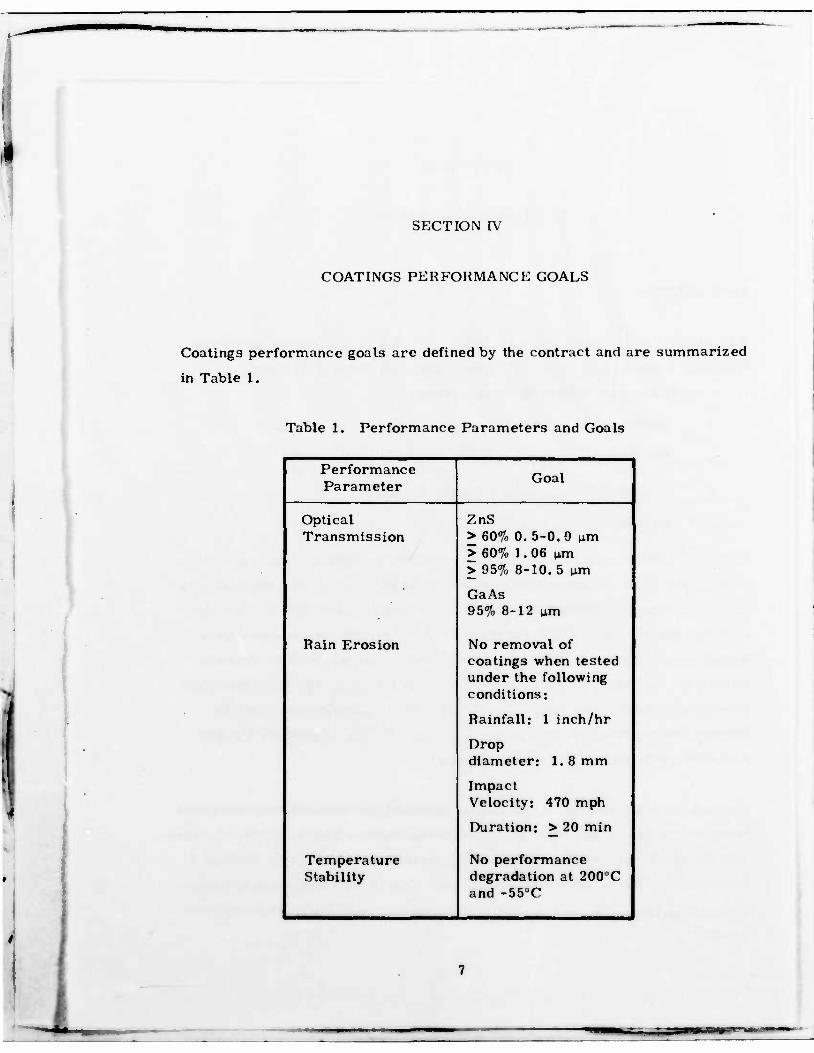
SECTION IV
COATINGS PERFORMANCE GOALS
Coatings performance goals are defined by the contract and are summarized
in Table 1.
Table 1. Performance Parameters and Goals
Performance Parameter
Goal
Optical Transmission
ZnS > 60% 0. 5-0. 9 u,m > 60%, 1.06 urn > 95% 8-10.5 urn
GaAs 95% 8-12 urn
Rain Erosion No removal of coatings when tested under the following conditions:
Rainfall: 1 inch/hr
Drop diameter: 1. 8 mm
Impact Velocity: 470 mph
Duration: > 20 min
Temperature Stability
No performance degradation at 200°C and -55°C

SECTION V
IR WINDOW MATERIALS
ZINC SULFIDE
Raw sample window substrates of ZnS (1. 5" x 0. 5" x 0. 2") were purchased
from the Raytheon Company. They were polished at the PTR Optics
Company to meet the following specifications:
• Flatness: IX in visible
• Parallelism: 3 minutes
• Scratch, dig and surface finish: 60/40
• Edge rounded to 0.08"
The large ZnS window (6" x 4" x 0. 5") was ordered from the same vendors
to meet the above requirements except that the parallelism specification was
20 arc seconds. Receiving inspection at Honeywell showed that the scratch
and dig requirement of 60/40 was not met while the other parameters were
within specification. A photo of a representative surface area is shown in
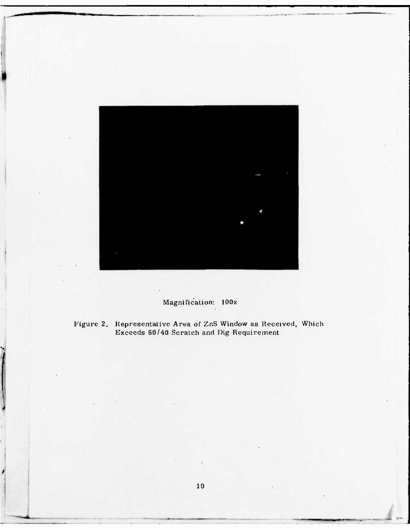
Figure 1. Additional substrates of ZnS were polished by Advanced Materials
Fabrication Optics Company, Woburn.MA. These samples exceeded the
scratch and dig requirement and were typically 40/20. A photo of a repre-
sentative surface area is shown in Figure 2.
The optical transmission of ZnS window samples, as received, was measured
between 0.4 and 14 urn. Results are shown in Figures 3 and 4. Figure 3 shows
that the short wavelength absorption edge is shifted from 0. 34 p,m (expected
for intrinsic ZnS) to approximately 0. 8 p.m. This is very likely due to excess
zinc and/or impurities and the polycrystalline nature of the ZnS window sub-
strates.
• - — *

Magnification: lOOx
Figure 1. Representative Area of ZnS Window as Received, Which Does Not Meet 60/40 Scratch and Dig Requirement
\
Magnification: lOOx
Figure 2. Representative Area of ZnS Window as Received, Which Exceeds 60/40 Scratch and Dig Requirement
10
_

-
0.9
EXPECTED ABSORPTION EDGE (3.6eV = 0.34 y)
0.3 0.5
JVU-^J % -
1.0 1.5
WAVELENGTH (ym)
2.0 2.5y
Figure 3. Short Wavelength Absorption Edge of ZnS Window as Received
11
oc
o oc o
o o
•f. 0 Ixl 0 co
UJ 00 y: a f— rs — to z OC z iij
o o s» 3: </) %
=> 0 «J _J • 0 zo 0 •-• z CVJ
§
SP a o ü 3 o
cd h
-t~->
1 <D
3 (73
O c
c o
••H 0) cn
cfl
3 bo
§ o o <\1
(X) N0ISSIHSNW1
12
1

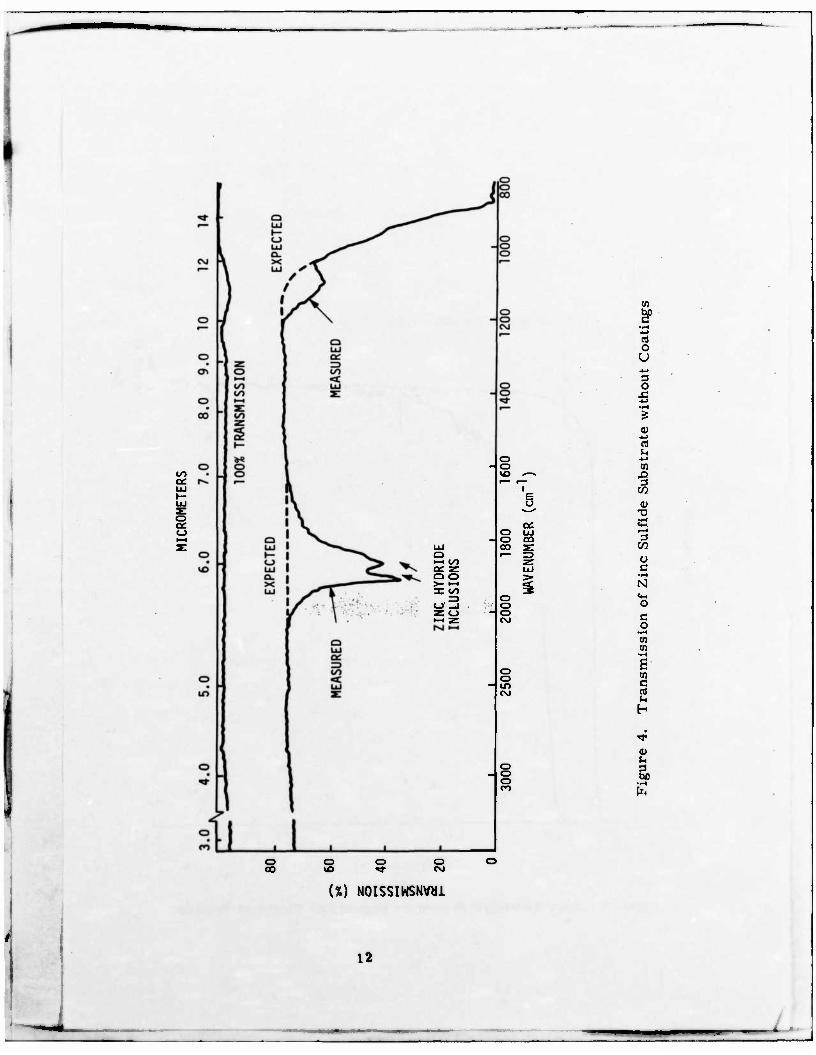
The two transmission minima at approximately 6 p,m (Figure 4) are very
likely due to inclusions of zinc-hydride (according to Raytheon). Except for
these two transmission disruptions the average transmission between 1. 5 pm
and 10 y.m is about 75 percent. The long wavelength roll-off of the spectral
transmission characteristics, shown in Figure 4, starts at about 10 p.m.
The expected roll-off should start at about 10. 8 p.m. Due to high window
absorption at wavelengths less than 0. 8 p,m and larger than 10 p.m. the
transmission goals for coated ZnS sulfide windows were not met between
0. 5 um and 0. 9 p,m and between 10.0 p,m and 10. 5 p.m.
GALLIUM ARSENIDE
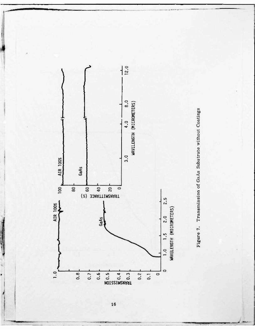
Small polished substrates of GaAs (1. 5" x 0. 5" x 0. 2") and a large sample
(6" x 4" x 0. 5") were received from AFML. None of the GaAs samples met
the scratch and dig requirement of 60/40. A photo of a representative
surface area is shown in Figure 5. Typical transmission characteristics of
the GaAs samples, as received, are shown in Figures 6 and 7 for the wave-
length range between 0. 5 p,m and 12 urn. Figure 6 shows that the short
wavelength absorption edge is shifted toward longer wavelengths. The long
wavelength transmission roll-off shown in Figure 7 starts at about 11.8 urn.
The average transmission between 2.0 p,m and 11.5 p.m is approximately
60 percent.
13

Magnification: lOOx
Figure 5. Representative Area of GaAs Window as Received, Which Does Not Meet 60/40 Scratch and Dig Requirement
14

0.9
«"<<*>» Y^^^
0.8 -
0.6
0.5
£ 0.4 c/)
0.3
0.2
0.1
EXPECTED ABSORPTION EDGE (1.43eV « 0.86 v)
0.5 1.0 1.5 2.0
WAVELENGTH (um)
2.5y
i
i Figure 6. Transmission of GaAs Substrate without Coatings
15
I
)
r a
• If) oo ac
o o o
o
o CO
en
V .rt -«-> cd o U *-> 3 O A +* •^H
is <U -u ni U -<-> oi ,0 3
CO
| rt Ü «M o c o
•t-1 LT> 01 • 01 CO •r-C
s oo OS 8 UJ rt
2.0
OMET
cc »—1
• t-
X IT) a> i— 3: £
1— be U5 •(-4 z ÜÜ
00
d o d ir> TJ- co
odd N0ISSIWSNW1
d d
16
SECTION VI
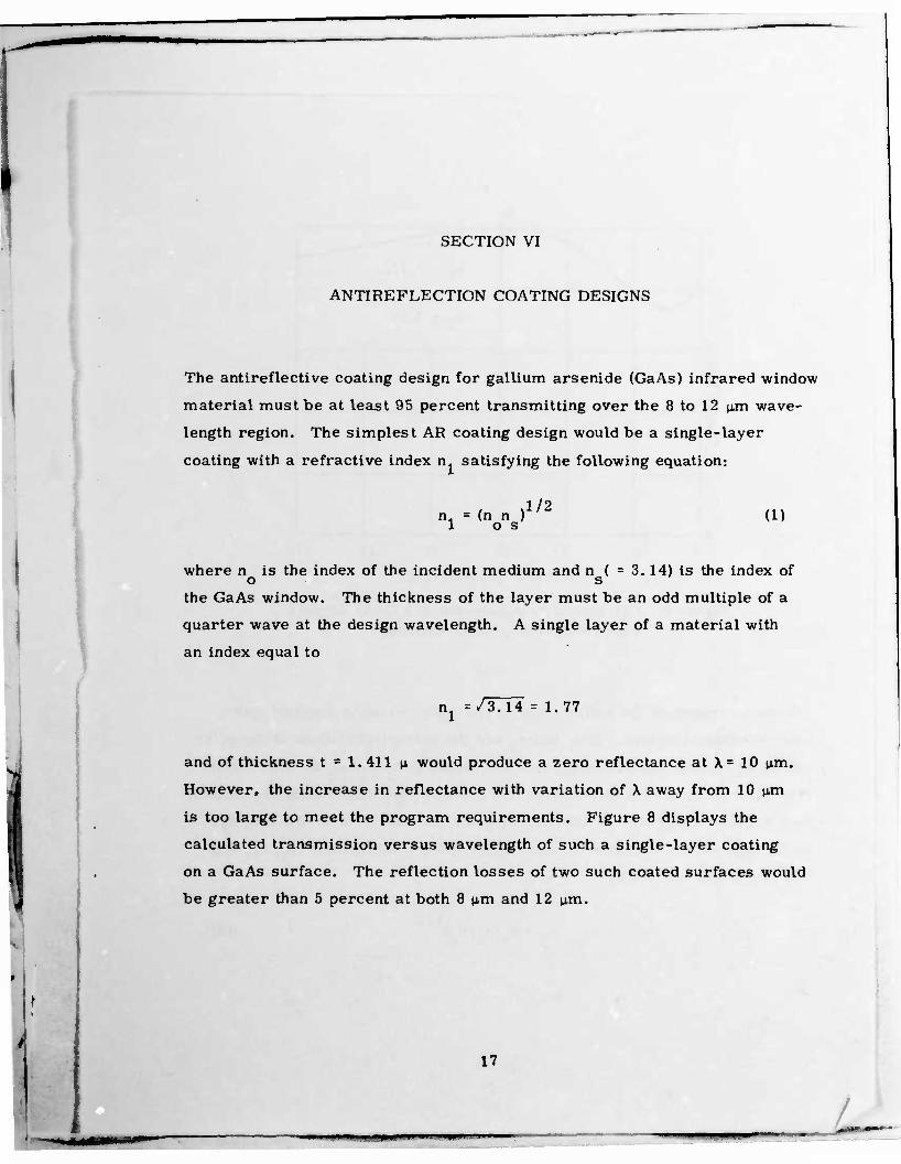
ANTIREFLECTION COATING DESIGNS
The antireflective coating design for gallium arsenide (GaAs) infrared window
material must be at least 95 percent transmitting over the 8 to 12 p,m wave-
length region. The simplest AR coating design would be a single-layer
coating with a refractive index n1 satisfying the following equation:
n = (n n ) 1 os 1/2
(1)
where n is the index of the incident medium and n ( = 3. 14) is the index of o s
the GaAs window. The thickness of the layer must be an odd multiple of a
quarter wave at the design wavelength. A single layer of a material with
an index equal to
nx =/3.14 = 1.77
and of thickness t • 1.411 p, would produce a zero reflectance at X= 10 p,m.
However, the increase in reflectance with variation of X away from 10 |im
is too large to meet the program requirements. Figure 8 displays the
calculated transmission versus wavelength of such a single-layer coating
on a GaAs surface. The reflection losses of two such coated surfaces would
be greater than 5 percent at both 8 p,m and 12 |j.m.
17

1= z: I/O z i
^^-^
nl=
1.77w ^^^^^^^^^^^
II II
i— v
t
1.411p
3.14
-
8 10 12
WAVELENGTH (MICROMETERS)
14 16
Figure 8. Calculated Transmission of a GaAs Surface with a Single-Layer AR Coating
A broader region of low reflectance can be achieved using double-layer
anti-reflection coatings. If n.. and n are the refractive indices of the outer
and inner layers, respectively, then the values of n. and n for which suit-
able adjustment of film thicknesses can produce zero reflectance are defined
by a Schuster diagram. A Schuster diagram for double-layer AR coatings
on GaAs is shown in Figure 9. Refractive index combinations (n , n ) that
fall on the line defined by
n = n (n /n ) & 1 s o 1/2
(2)
18
*••*••

nl = Kns] 1/2
2 ' "UVV 1/2
1 2 3 4 5 6
REFRACTIVE INDEX (^ ) OF OUTER LAYER
Figure 9. Schuster Diagram for Double Layer AR Coatings on GaAs [AR Coatings designs exist for points (n,,n0) in the hatched areas.]
represent the special case where each layer is X/4 thick. Combinations
(n., n.) that fall on the curve defined by
n„n„ • n n 12 os (3)
19
_

have layers of equal thickness which are, in general, not integral multiples
of one-quarter wavelength thick. AR coatings with indices satisfying Equa-
tion (3) produce a zero reflectance at two different wavelengths and there-
fore provide a broad region of low reflectance.
As the point (n , n ) is moved along the n n = n n curve towards the line A/2 defined by n„ = n1(n /n ) , the difference between the two wavelengths at
Ci ISO
which zero reflectance occurs decreases; and, at the intersection of the
two curves, a broad region of low reflectance with zero reflectance at a
single wavelength is obtained. The program requirements can be satisfied
with a double layer AR coating whose indices lie close to the point defining
the intersection of Equations (2) and (3). For GaAs these indices can range
from 1. 3 to 1. 7 for n and from 2. 3 to 2. 6 for n .
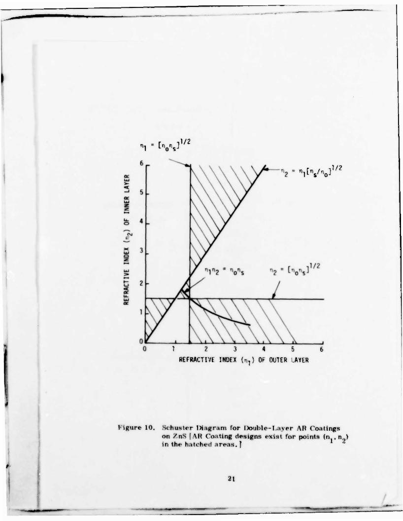
A corresponding Schuster diagram for double-layer AR coatings on ZnS is
shown in Figure 10. The critical ranges of indices are 1.0-1.6 for n and
1.5-2.4 for n . ...
A large variety of coating candidate materials was originally examined
based on qualifying refractive indices. Coatings combinations which were
selected and actually fabricated on GaAs and ZnS windows are listed as
follows:
20
- r iV2
*itV%3 1/2
1 2 3 4 5 6
REFRACTIVE INDEX (*.] Of- OUTER LAYER
I iRure 10. Mattr Diagram for Double- I aver AH Coatings on /t\S | \H Coating designs exist for points (n . n,,) in the hatched areas.]
21
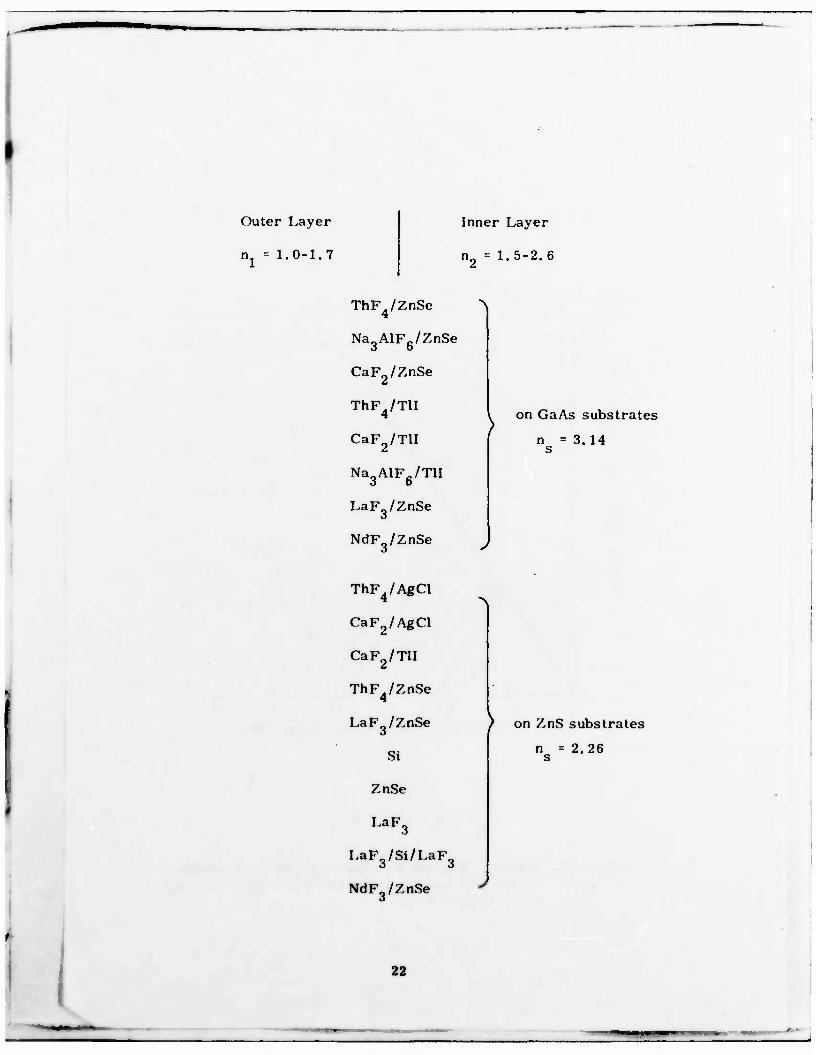
' Outer Layer Inner Layer
nl = 1.0-1.7 n2 - 1.5-2.6
ThFjZnSe 4
"N
( Na_AlF„/ZnSe
6 0
CaF2/ZnSe
ThF^/TU 4 , on GaAs substrates
n =3.14 s CaF2/TU
Na,AlFc/TlI O 0 1 LaF3/ZnSe
NdF /ZnSe >
ThF4/AgCl >
CaF2/AgCl
CaF2/TU
ThF„/ZnSe 4
LaFg/ZnSe ) on ZnS substrates
Si n =2.26 s
ZnSe •
LaF3
LaF3/Si/LaF3
NdF3/ZnSe J
:
22
^_^_ ^__ '
Evaluation of transmission and reflectance characteristics of coated test
samples demonstrated general agreement between calculated and measured
data.
Failures during testing for adhesion, solubility in water, humidity resistance,
and rain erosion resistance reduced the original materials candidates pro-
posed to the following coating materials: Si, NdF„, LaF , ThF and ZnSe.
These materials became the prime coating material candidates because of
their demonstrated durability to abrasion, humidity and rain erosion.
The calculated reflectance as a function of wavelength for double-layer
coatings combinations on GaAs are shown in Figure 11 for ZnSe and ThF.,
and in Figure 12 for ZnSe and NdF_. The calculated reflectance of double
layer coatings on ZnS are shown in Figure 13 for NdF and ThF., in Figure
14 for ZnSe and LaF_ and in Figure 15 for ZnSe and NdF„. A three layer
combination of LaF_/Si/LaF„ on ZnS is shown in Figure 16.
A summary of refractive index, coefficient of thermal expansion and trans-
mission limits of the prime coating material candidates is shown in Table 2.
23
«*»" «-•
- • i m r •*" ny
. 1
<: at UJ r-
2 u. JE 1—
01
c r>i
O UJ
3 VO «2 Mi
II
3
o 00
o II
CM -o
UJ 1—
oe i— «•> CO
X U_ UJ UJ Q OC Z
in ro
ii
r—
CM
II
(VJ
5
ll
V)
I
a» CO LO
o
o o o o
a: r-
z UJ .-J UJ
en 00 in 10 vo
i 33NV133U3a
3 CO Ü c o a>
c N
P
be c;
•<-" -* -> c3 O u u
•»
•§ o Q
0) u c iS o
<t-l
0) K
3 O
PH
h a> D
i o u
a> fa 3 be
24

CO
<c •—• qt LU
i
oo LL. •o SB
a« CO c
IVI
J_ üüi
M
C3 1
1—
PHYS
ICA
L TH
ICK
NES
S
3. r-» 00
II
3. Cf> CM 10 o II
CM •o
UJ 1— | CO 00 =3 CO
5 CM
II
CM tr
oo
II
f/>
X U. UJ LU O
! oo in
ii
•
o o 33NV1331J3M
rt Ü
en c oo o un *• 0) • CO oo c ' SI
*"•»
h 73 2 «M o bo c
•»4 ÄJ cd O Ö M
co a» oc >> UJ cd (- UJ J z: o 0)
o -9 •-* 3 z: O
Q o o <W o o o m o o r— c
aS 31 4# E CJ cs $ z UJ c _J 0) UJ K 5» «t IM 3 O
«# 3 O A C
Ml w a, M 5
•u 3 a | o
e* U CO 00 10 CM
U3 r-i
m s fc* •H G
25
• —

or D \— U.
1-
ro U. "O Z
1/1 c
1
PHYS
ICAL
THIC
KNES
S
r^
Co o II
o
II
rsj
UJ »-
h-
CD
X U- UJ UJ O or z
•—1
M CO
II
c
oo M ^— li
CM C
CM
CM
II
l/l tr
•
en 00 LT)
1/1 at:
o
o o o o
o
0> co If» VO
VO
i 3DNV1D31J3«
CO c N c o
or
bo c CO o U Li 0)
a) J
3 O Q
0) u c cfl *-» CJ a> C 0/ K
3 o
IX Li <U *J 3 a E o u
cv U 3 be
1 u
CO 01 oo
3 C J INI
3 O
c z INI *-
3
1 /
oo in
o o o
13
cr> IT)
c N c o • c N
CO
h CO
c •fH •w
CB O U h a> >> CO
0) U c tfl
u a>
a> 05
s 3DNV1331J3cj
3 O
<u 3 a s o U
§1 ••H
27
—
1 ' _l
m UJ t- X
m U- T3 Z
• I/) c M
T
IS) C
l~>l 1
>
PH
YSIC
AL
THIC
KN
ESS a»
ii
T3
o ID
II
CM •o
UJ
2 »— l/> CO
M
X , U- UJ
UJ o cc z
co to
II
e
«T
CM
II
CM C"
CM
CM
II
Cd er
I
N er« c 00 o IT) *»• 1 • C/) O c ' N -—
CO
h TJ £ v- O
gf
a:
o
o o o o
o
CX> co in io io
3DNV133nd3M
h <u >> cs J cu
s cu o c CO ~- o CV
C ti a
3 O
Ä 3 a
i u m T-l
28
/ * • — • -^i

CXI oo in
ro CO o j- •r— U_ CO Q <o CO IB tz z _i _l IVI 1-1
CO c N c o c
a)
17}
fe CO
J <n O g, s o U h 0 >> CO
HJ
0) CO (D OC t-, LU £ LU £-> z: o co DC <<H O o •—i z: V
u o o o
c rt o o o cu
cu i— K is «H z o LU _l itS
LU 3 > O < 4A 2 c
.«H
fi (H a> *4 3 a. S o 0
CTt Lf>
CO
30N\/1031J3a
29
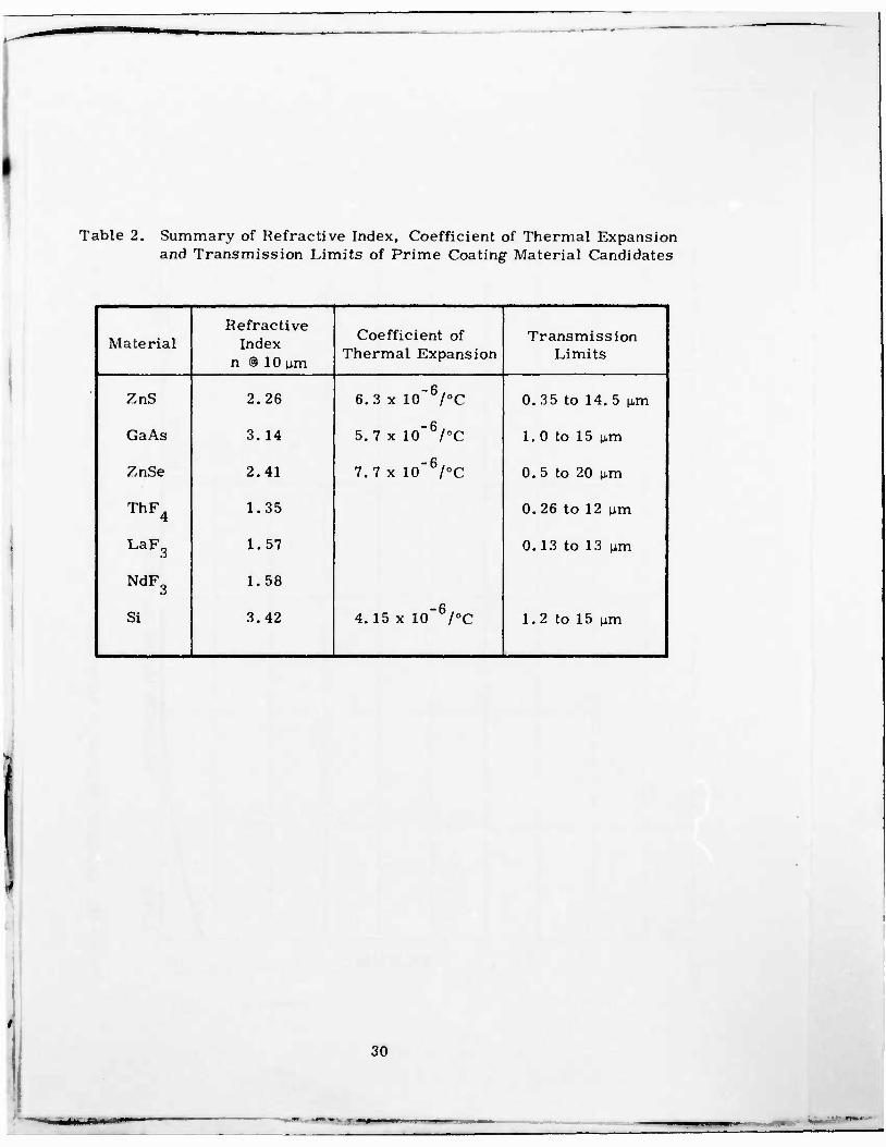
Table 2. Summary of Refractive Index, Coefficient of Thermal Expansion and Transmission Limits of Prime Coating Material Candidates
Material Refractive
Index n @ 10 tun
Coefficient of Thermal Expansion
Transmission Limits
ZnS 2.26 6.3 x 10~6/°C 0. 35 to 14. 5 p.m
GaAs 3.14 5.7 x 10_6/°C 1.0 to 15 |im
ZnSe 2.41 7.7 x 10" /°C 0. 5 to 20 um
ThF„ 4 1.35 0.26 to 12 M,m
LaF3 1.57 0.13 to 13 M-m
NdF3 1.58
Si 3.42 4.15 x 10"6/°C 1.2 to 15 p,m
30

SECTION VII
COATINGS FABRICATION
The preparation of coatings on ZnS and GaAs substrates was performed
using the electron beam vacuum deposition technique. The process is docu-
mented for ZnS and is presented in the Appendix. Major variables of the
coatings preparation were:
Surface cleaning of substrates
Purity and pre-conditioning of source materials for vacuum
deposition
Pressure during deposition
Substrate temperature during deposition
Deposition rate
Coatings thicknesses
Duration, temperature and environment of post-annealing
Temperature versus time profile during cooling
Cleanliness of deposition and post-annealing facilities
Process control was maintained by monitoring substrate temperature, de-
position rate, vacuum pressure, coating thickness and by following step by
step the process in the Appendix. Deviations from the process procedures
were recorded in a log book. Materials are identified according to vendor,
Lot No., grade identification, and impurity content. All coatings were
prepared from identical source materials.
31
nw>

Using Honeywell's computer program for optical coatings design, the physi-
cal thickness of each layer was calculated for optimum transmission and
reflectance characteristics. Calibration of physical thickness, versus
frequency shift of the quartz crystal thickness monitor in the deposition
chamber, was carried out. The physical thickness of coatings on test
samples was measured using a Sloan Angstrometer.
32
SECTION VIII
OPTIMIZATION OF FABRICATION PROCESS AND COATINGS DESIGN
Optimization of the coatings design was conducted primarily by
• Selection of coating materials which passed rain erosion
testing
• Adjustment of physical layer thicknesses to provide optimum
optical transmission characteristics over the required spectral
ranges
• Selection of sufficiently high substrate temperature during
vacuum deposition and post-annealing in order to provide a high
degree of layer crystallinity, good adhesion, sufficient temper-
ature stability and enhanced rain erosion resistance.
Representative transmission and reflectance spectra of optimized two layer
coatings on ZnS and GaAs window samples are shown in Figures 17 through
22. These figures are:
Figure 17. Transmission of Coated ZnS Windows between 0. 5 and
2. 5 \LTT\
Figure 18. Transmission and Reflectance of Coated ZnS (ZnSe/NdF )
Before and After Post-Annealing
Figure 19. Transmission and Reflectance of Coated ZnS (ZnSe/ThF )
Figure 20. Transmission and Reflectance of Coated ZnS (ZnSe/LaF ) 0
33
i
Figure 21. Transmission and Reflectance of Coated GaAs (ZnSe/NdF )
Figure 22. Transmission and Reflectance of Coated GaAs (/.nSe/ThF.) 4
N
34

REQUIREMENT
ZnS/ZnSe/ThF,
#10676
100
90 M
80 z o #10676 a
60
50
40
I z 2
0.5 1.0 1.5 2.0 2.5i
Figure 17. Transmission of Coated ZnS Windows between 0. 5 and 2. 5 um
35

100 r
z «I >—
1/1 M
l/> at 5
8 9
WAVELENGTH (urn)
Figure 18. Transmission and Reflectance of Coated ZnS (ZnSe/NdF ) Before and After Post-Annealing
36
LU o <c I— o LU —I U- LU DC
o I—I «/) «/>
i 1
WAVELENGTH (pm)
Figure 19. Transmission and Reflectance of Coated ZnS (ZnSe/ThFJ
37

PERFORMANCE GOAL
REFLECTANCE
8 9
WAVELENGTH (um)
10 11 12
Figure 20. Transmission and Reflectance of Coated ZnS (ZnSe/LaF,) 9
38
— •..,,. 1

*«
o
It-
100
90
80
70
60
2 50
PERFORMANCE GOAL
GaAs/ZnSe/NdF-.
BOTH SIDES
#12276 12-6-76
REFLECTANCE
-"- 7 8 9 10 11 12
WAVELENGTH (ym)
Figure 21. Transmission and Reflectance of Coated GaAs (ZnSe/NdF )
39

100 ••—r
PERFORMANCE GOAL
GaAs/ZnSe/ThF4
BOTH SIDES
#4676 4-6-76
HAVELE:,GTH (um)
Figure 22. Transmission and Reflectance of Coated GaAs (ZnSe/ThF ) 4
40
m '•• • —

SECTION LX
OPTICAL PERFORMANCE OF COATED WINDOWS
VERSUS PERFORMANCE GOALS
The optical performance of coated ZnS and GaAs substrates versus perfor-
mance goals is summarized in Table 3.
Table 3. Optical Performance of Coated Windows versus Design Goals
Requirements ZnS GaAs
> 60 percent trans- mission; 0. 5-0.9 M-m
Met at 0. 9 p,m; not met at <0.9 (i.m due to substrate absorp- tion.
Not applicable.
> 60 percent trans- mission; 1. 06 \im
Met Not applicable.
> 95 percent trans- mission; 10. 6 \tm
Met at 8-10 ^m; 85-90 percent at 10. 5 \im due to sub- strate absorption.
Not applicable.
> 95 percent trans- mission; 8-12 M-m
Not applicable. Met at 8-11 pmj 85-90 percent at 11-12 \>m. due to substrate absorp- tion.
41
ZINC SULFIDE WINDOWS
Data (Figures 17 through 20) show 62 percent transmission at 0.9 pm and
1.06 p,m and 95-97 percent in the range between 8 p,m and 10 n,m. This means
that the performance goal for optical transmission is met at 0. 9 um, 1.06
p.m and in the wavelength range from 8 (im to 10 p.m. The performance goal
is not met in the wavelength region between 0. 5 \im and 0. 85 p,m due to the
shift of the absorption edge of the ZnS windows from 0. 34 \im (expected in
intrinsic ZnS) to 0. 8 p.m (see Figure 3). This shift is very likely due to
excess zinc and/or impurities and the polycrystalline nature of the ZnS sub-
strate. The transmission between 10.0 p,m and 10. 5 \xm is between 85 and
90 percent and does not meet the program performance goal. The reduced
transmission is again due to substrate absorption. As shown in Figure 4
the substrate transmission starts to roll-off at 10 \m and not at 10. 8 p,m as
one would expect in pure ZnS.
GALLIUM ARSENIDE WINDOWS
Data (Figures 21 and 22) show 95-98 percent transmission in the wavelength
range between 8 p.m and 11.0 p,m which meets the program performance
goal. The program goal is not met between 11 and 12 pirn due to substrate
absorption. The transmission of the coated samples drops to about 90 per-
cent between 11 and 12 \um.
42
SECTION X
RAIN EROSION TEST DATA
Coated window samples of ZnS and GaAs (I. 5" x 0. 5" x 0. 2") were delivered
to AFML according to the delivery plan of the contract. The rain erosion
testing was conducted by AFML/MBE. The test facility simulates rainfall
of 1 inch/hour with an average raindrop diameter of 1- 8 mm and a raindrop
impact velocity of 470 mph. The variable is the exposure time to the above
specified rainfall conditions. The program goal was to withstand a minimum
exposure time of 20 minutes. Results of the rain erosion testing were re-
corded by AFML and submitted to Honeywell. This rain erosion data is
presented in Tables 4, 5 and 6. Significant results of the rain erosion
testing can be summarized and interpreted as follows:
1. In reference to sample AFML numbers 7189, 7548, 7549, 7550,
7552 and 7553, coating combinations of ThF /ZnSe, LaF /ZnSe
and NdF„/ZnSe on ZnS met the rain erosion resistance goal.
The rain erosion resistance of the combination NdF„/ZnSe was
superior in that it survived an exposure time of 30 minutes.
2. The same coating combinations on GaAs did not meet the rain
erosion resistance requirements as demonstrated with samples
number 7185, 7437, 7438 and 7551.
43
c
K •D
g •i-t
w
3 O X
in c a.
I—1 0 1—t
1 0 i u •j <-> 0 g c CO
•a Q en M
2 g w g a«
3
fa a 01
fa 01 5
0
o
* , 3 O CO
CO CO
v. E o o
CJ
0 « E
o
'S t) fa 3
fa 3
OJ fa
4) fa 3
i 1
A en CO ll (0 CO fa c« a o) p & 01 fa 0
a 0 O. "cO
2 S en
CO T3 tn
3 cO X X E en
T3
3 « en jS
T3 CO
c E
• o S E
CD 01
E u
01
E o .
CO
o a X u
> o E S
01
0) fa o
OJ
0 fa o
BO C
'fa 3
•o
E 0
•a 01 M (0 C
E
E
w en c o fa <»* w
i2 c Of
I 0 0
•o 0)
>>* rt co
c 1 - o>
s «, c ra •D 'fa
3
U) c
CO
4) JO
(t-l o
01 J3 <*_ 0
> o £ 01 >
0 E u
'S 4>
a E 0
01 s>
8.5 .s >> 0) 0
3 { .
0* fa
E E •D CO
Shi a a v VI |J ^
fa — p n « fa »5« i« £ o
g SPä I - 0) > n S i 0 " en o a
> 01
i £ E o o> tn u c >> —
• £ Q. CO
o —
co 3 0 u) o _ M c C
0
2 «1 to'
3 OJ CO
ä o E 2 1 8
> o E 01 fa >*.
"3 'S 'S. E o
•D
•0 ft) JÜ
CO
M c
CO
0 U
o o
0
eo
0 a eo
0;
CO
tu c
£ 0 ej
at c
M 0 0
on c
E o Li
M c
n 0 O
fa
% & en
a .5 £ e o E O 0» w fa eo „ 0 c/;
o 01 fa o u 5j 4, fa 60 CJ "5 I-' C
c 3
c 3
> M 4J £' c o
c 3 »B an
c c 3
eo c 3
c 3
n fa h
6 3 fa — 0 3
fa B fa CO 5 VI 8 CO
fa o "2
CO fa fa r^fa
0 ° 'S 0 0 0 a' o E 0 0 J= £
U S-. n Z. su; SB ecu o U Z «i cr 2 Z H *
• s £ £ P 7 0» Q.
•s* 1 i *r • m •H o -»• i (-H t i •f
a 1 d r i d I o d d o i d • • b CO CO
H
i a eo eo E 0J (A (A C/". V. x K e/: e/; t/3 IT. < < c/: • c C C c c c c c c C c CO CO c
M N X M N N N t\' N M N Ü Ü N
« 6 k X U, F k b. fc o o b • o d
o in in o iT) o 1 ? IT) ^i «N in CN IT)
•— V i» * £ ä rj —
5 u CO •
.s • • 01 01
k CO
J 01 a 01 01 D £ tA t/5 U1 e/l C/l er. ra
"rs C c c ~^ c c c d c B CJ
0 3 s; N S i/i !NJ SI N s: N
eo n 4» • CO n *• CO CO CO «r v n1
w L, a. X. cr. ii. m k U< k k X k Qbi 3 i (U c c ro M £ ^ rt CO £ £ £
* — M N; s: •" P x a •9 J f- h
_ O O M • m CO t- CO C7J O rj
J" 0 0*> o o o b O O o o o O k z O o o o O o o o o o O o O o t~
• t- t- t~ r- t- o t- c- t- r- l^ 1— t-
44
cd 1 cö K TJ <U
CÖ 1-*
3 £
35
*J o K .c ^ o « c a l-H o
i Q i rrt tn
-*-» CU fll •*->
Q c s 3
B o S
W fi c 00 rrt « K rH
• in
V —•>
•8 H
p If w
C I 5 » i 3
U
C >>
Sj ti * e —
c/i 2 u, <
o 2
o g
rt o S E rt «I e B
&s * 2
5 G " »I I * « H * » I
I 2 £ j | 5 „'S a>
r <n «
C 4
3
H
a> <
tn
o £ S
V In
3 V
15
TJ f .
I ti « t. o
2? I 8 « a o fi
in t>
o «
ti Z > 01 o a E<g ti WJ
G
5 I di o
E t.
8* to C
fe, N « 1- i-l o
O 1 as
ti
s i o E ti
o.-* * "
" 1 5
i i § CUD "
S « Of'Za e« ti
Kort
ti a
o I
o I c I
> o E
0/
a E o
8
T3 ti > O
SfJ *• •S 3 rt c
61 3 O
5
OT 5 C « N Ü
tn < 'S' in c rt c c N O N M
t/3 10 C c N N
c N
tl tn
ti 1 ti in
c c c c N N N N ^ *^. « m *r < h k h U. rt rt
J P
rt 1 1
1
rt
C rt
rt
5
1
45
Hj i •-< a K •u V -*-» ca — 3
£ -.-" c/; t. 3 O B £ _^ O m c a
l—< o u
1 P rrt ^ •*-j ai ft -*-> Q c
0)
s 9 u •r-i a
o 6 W E a 00 01 • K 1-H
a> —•
s
1 0 1 * E 01
US >
o V-
1 _ T3 re 1
a a c
o
•D •o
a> _ > a
* 0
je 0 n
E Oi •o
Q. 01 i > > E o
X 01
0i > X 0 o E 0 B E e • 01
re t- M C £ •o «< a a • Oi
u E E B u > E > X
c M c
M B 2 a E s •j 0
E • c
0 £
B 01 -P c p
o 01
§ « n l. s u re u
0 0
0 o
0 BO — C -
> tu c
0 0 on
c
's 0 « S "5 cj B 0 m i. 1
• (J E E
o e ü V o —
> 0
£ s h
0 rt
0 (0 c o
c i o E
O « c u
> c B 1 u
0) a.
6 a £3 M i-a 01
a Ä a. bfl
3 « B C "2 o — 0 c
o o TO (j o a o 00 m
** ,, U n tu £ Cfl r- w en 2 w «- C SJ E o c c o M c O Ö 3 g oi a 5 o "^ 01 L. 3 i, L.
cj 0 o to o o — rt n cj 0 CO o A xt ,<", 5 o o S
— c XI 0
< < W n o Z o <; 'S
- 8 5 § 6 p *"
£ o a
9 £ in \T> o o o ^H o o
CO M CO PO CM
S P 9 P B>5 X u
Oi
E to < < e
00 s
to < BQ
c c
1 Ü N N t-J C3
Ü N N
W
M h
m « ? «1 w • 01 8 01 B Oi fi en 4» VI U3 W3 tn tn tn tn VI
5 h
C Q c B c c c B N N N N N N N N
... 4» CO CO CO CO CO ^r CO CO
.5 « b h u. U. '* U. b h •D •o 2 •D T3 £ «j T>
3J s z z B h- J z 0 0 C 2
'm
B *"
B * s • BJ to a CD (£1 (O
H ^' r* r- t^ r- r- r» CO t* M r- t- CO in t* o M c M M 00 ro
C 0 ao C0 en O) a> r» to CO i x £ 01 ,
O- • t- CO CO Ol o M ffP CO *r * in in in in
b. *r *r lO in in in n in
< c- r- t- r- r- c- t- t-
— •o
o c
e
46
3. Based on a comparison of erosion test results of October 12
(Table 6) with those obtained previously, the rain erosion resis-
tance of coatings on ZnS windows with good surface finish
exceeding the 60/40 scratch and dig requirement (October 12
data) are superior over coatings on ZnS windows with poor sur-
face finish which do not meet the 60/40 scratch and dig require-
ment. Figure 23 shows the increased coating damage from rain
erosion around two scribe lines in the window surface which
were made before coating of the sample was started. The
scratch mark in Figure 23 was caused by the edge of the
mounting fixture of the erosion tes.-r. The coating damage
around the scribe lines is evidence for increased damage rate
around imperfections such as scratches, pinholes, etc.
4. The result that the same coatings combinations which survive
erosion testing when prepared on good ZnS windows fail when
prepared on GaAs windows may be related to the extremely
poor surface conditions of the GaAs windows. Repolishing of
GaAs substrates was recommended but appeared beyond the
scope of the current program.
5. Spectral transmission characteristics of coated ZnS windows
measured before and after erosion testing exhibit a degradation
of transmission of up to 10 percent due to rain erosion. Repre-
sentative data is shown in Figure 24 for the NdF_/ZnSe coatings
combination. Microscope pictures taken at Honeywell and AFML
show some internal fracturing of ZnS windows after rain erosion
which could account for the reduced transmission. Typical inter-
nal fracturing is shown in Figure 25 (Honeywell photo).
47
SCRATCH MARK
SCRIBE LINES
Figure 23. Increased Coating Damage from Rain Erosion Around Two Scribe Lines
48
.
loo r
a«
LU o z I— o
in
2
TRANSMISSION AND REFLECTANCE BEFORE AND AFTER RAIN EROSION TESTING
ZnS/ZnSe/NdF,
#91576 9-16-76
A • BEFORE RAIN EROSION TESTING
o a AFTER RAIN EROSION TESTING 470 mph FOR 30 MINUTES (1 INCH/HR RAINFALL)
WAVELENGTH (vm)
Figure 24. Transmission and Reflectance Before and After Rain Erosion Testing of Coated ZnS Window
49

Magnification: lOOX
Figure 25. Internal Functioning of ZnS Window after Rain Erosion Test. Photo Taken from Uncoated Side of Window.
50
_^-—
SECTION XI
VALIDATING MEASUREMENTS
Validating measurements include:
• Transmission measurement at room temperature and 200°C
• Wavefront distortion measurements at 1. 06 p,m and 10. 6 p,m
modulation transfer function calculations
• Optical homogeniety An/£x of the AR coatings
• Solubility, humidity, salt spray and abrasion resistance and
adhesion properties in accordance with military specifications
Results of validating measurements will be presented in an addendum to
this report.
51
urn wm« *- «—»••- • i '——'— in- •!—~~~Tf

APPENDIX
FABRICATION PROCESS OF EROSION RESISTANT AR COATINGS
FOR ZnS IR WINDOWS
52

Mt-151 Honeywell GOVERNMENT AND AERONAUTICAL PRODUCTS DIVISION CODE IDENT NO 94580
ENGINEERING SPECIFICATION NO. ES Draft
THIS Q SYSTEM
ENGINEERING SPECIFICATION IS FOR:
LIST DEVICE AND/OR SUBASSEMBLY
D DEVICE D ASSEMBLY 3 OTHER
Fabrication Process of Erosion Resistant AR Coatings for ZnS IR Windows (Contract No. F33615-76-C-5039)
SIGNATURES »«£P»R£D BY
»fPnovcn %v J. Brown/W. Doerffler
Mgjici ENG». H.Y.B. Mar
Nov. 1. 197 i
REVISIONS
LT* DESCRIPTION DATE APPROVAL LTR DESCRIPTION DATE APPROVAL
PAGE 1 REVISION
PAGE PAGE 53
REVISION ES
GOVERNMENT AND AERONAUTICAL PRO
ENGINEERING SPECIFICATION NO.
1.0 Materials and Classification
DUCTS DIVISION
CODE IDENT NO . 94580
|ES Draft
Material Vendor Classification and
Specification
LaF3 CERAC/Pure Inc. Milwaukee, WI
1/4" pieces fused, 99.9% (Stock #1-1114) (Lot #4155)
ThF„ 4
CERAC/Pure Inc. l/2"-l/8" lumps. 99.9% Anhydrous (Hi-Pur. Optical Gr.), (Stock #TS-106) (Lot #5125)
ZnSe CERAC/Pure Inc. 1/4" pieces fused, 99.999% optical grade (Stock #Z-1014 (Lot #2297)
NdF3 Research Chemicals Div., (Nuclear Corp, of America) Phoenix, AZ
1 to 2 Li particle, 99. 9%
ZnS windows (polished)
Raw substrates: Raytheon Company Polishing: Advanced Materials Fabrication Optics Comp., Woburn, MA
Provided by AFML
1.5" x 0.5" x 0.2" Flatness: 1 Xin visible Parallelism: 3 minutes Scratch and dig: 60/40 Edge rounded: 0.08"
6"x 4"x 0.5" Same as above except Parallelism: 20 arc seconds
GaAs window (polished)
Required as above
REVISIONS
LTO ofSC PTION DATE APPROVAL
PRM 54
ES

Mt -It i Honeywell OOVIMNMNT AND AtftONAUTICAl HK
ENGINEERING SPECIFICATION NO.
WUCTf OIVWO* COM IDENT NO 94S80
|ES nraft |
2.0 Instrumentation
Honey well Identification No. Description of Facility
H-l 650-031 Electron Beam Vacuum Station No. 4 18" Bell Jar 6" Diffusion Pump NRC
H-2 Metal Dessicator with Siligel and Molecular Sieve
H-3 510-5601-001 Sloan-Six/Ten Electron Beam Power Supply and Control
H-4 808-0101-001 Sloan-Y-Axis Beam Control
H-5 808-0202-001 OMNI II--Deposit Thickness Monitor
H-6 350-0609-003 CVC-GIC 300A Ionization Gauge
H-7 • • •
•
•
Clean Bench 051-1122 Clean Bench A-2475 Degreaser MPG-695-001 (Trichlorethylene Vapor) Hood Enclosure EL8-5338
EL8-5814 Thermocouple Monitor
H-8 501-951 • Furnace (Blur II. Electric Co. ) Model BFD19
H-9 420-073 • Flowmeter N2 (Brooks) Type 5-1110 Full scale - 0. 487SCFM
H-10 EL8-5813 • Flowmeter O) (Brooks) Type 2-1110 Full scale • o". 015SCFM
«VISIONS i.n OCSCftlPTION DATC APPROVAL
•" 55
Et

Honeywell OOVtMMMNT «NOAUONAUTICAt MIOOUCTS DIVISION
'oof .r>tN' v =>«5t!
ENG IHEERIMG SPECIFICATION NO.
2.1 Work Environment
£ Draft
UM lab in which the substrates are cleaned MMl the < oatings are fabri-
cated have the following clean room conditions:
Dust/Ft'
Temperature:
Relative Humidity:
Static Pressure:
Filtration:
Clothing:
HK to fidK
65 to 70 I
4'( to 52 per« ent
None (positive pressure available)
Electrostatic and Absolute Filters
Smock
3. 0 Fabrication and Process Plan
The materials required for the fabrication of erosion resistant \H
coatings for IK windows are those described in Section 1.0. All mater-
ials are labeled and have been certified.
3. 1 Cleaning of Substrates
Note: New substrates are generally contaminated.
muiiM JM. MMMitHm o*u
56
ES
Honeywell GOVERNMENT AND AERONAUTICAL PRODUCTS DIVISION
COOE I DENT NO. 94580
ENGINEERING SPECIFICATION NO. ES Draft
3.1.1 Soak ZnS substrates for 1 hour in heated (150°F) microdetergent 3
solution, 1000 cm distilled deionized water. Use only clean
rubber gloves (surgical) for handlir B substrates.
3. 1. 2 Scrub both surfaces of substrates prepared under 3.1.1 with
cotton swabs.
3.1.3 Rinse with warm tap water, then with distilled deionized water.
3.1.4 Immediately follow with blow-dry with dry nitrogen gas directed
onto the surface of substrate at an angle such that no water drops
from the edges are blown across the surface. Place substrate
on lint-free (non-treated) tissue on a "clean bench" or directly
into vacuum deposition system.
3.1.5 Vacuum Deposition of Two Layer Coating on ZnS Substrate
The LaF , ThF., ZnSe, and NdF„ vacuum deposition is pe
formed in the bell jar vacuum system (H-l).
3. 1. 5. 1 Place substrates into holding fixture and attach fixture to the
substrate heater oven of the vacuum system, using four clips to
hold in place. Place thermocouple in hole provided in substrate
fixture.
JJR_ REVISIONS
-DEjcaimaL APPWOVM.
57
ES
HI -11 I Honeywell GOVERNMENT AND AERONAUTICAL PRODUCTS DIVISION
CODE I DENT NO. 94580
ENGINEERING SPECIFICATION NO. E3 Draft
3. 1. 5. 2 Install new oscillator crystal for thickness monitor in holder and
test thickness monitor for stable oscillation. Adjust for frequency
null on monitor. Trim and clean aluminum foil before use in bell
jar.
3. 1. 5. 3 Place source materials for first layer coating (ZnSe) and second
layer coating (LaF„ or NdF„ or ThF.) into different compart-
ments of the hearth of E-beam unit using a stainless steel scoop.
(Pack NdF material thoroughly with a pestle.) The hearths are
filled with materials to between 3/4 and 7/8 of their volume.
3. 1. 5. 4 Place clean Pyrex chimney over hearth.
3. 1. 5. 5 Close shutter.
3. 1. 5. 6 Close bell jar and mount protective screen onto vacuum system.
3.1.5.7 Roughing of Bell Jar (Mechanical Pump)
3. 1. 5. 7. 1 Check "cold baffle" for being filled with liquid nitrogen (N ).
3.1. 5. 7. 2 Monitor bell jar pressure (TC-1 gauge).
AH.
3.1.5.7.3 Close vent valve.
DESCRIPTION DATE APPROVAL
58 ES

Mt - < iI Honeywell GOVERNMENT AND AERONAUTICAL PRODUCTS DIVISION
CODE I DENT NO 94580
HE Draft ENGINEERING SPECIFICATION NO.
3.1.5.7.4 Close foreline valve.
3. 1. 5. 7. 5 Open roughing valve.
3. 1. 5. 7. 6 Continue pumping until pressure is well between 100 u. Hg and
50 n Hg.
3.1.5.8 Pump Down of System (Diffusion Pump)
3. 1. 5. 8. 1 Monitor foreline pressure (TC-2 gauge).
3.1. 5. 8. 2 Close roughing valve.
3.1. 5. 8. 3 Open foreline valve.
3.1. 5. 8.4 Slowly open gate valve so as not to exceed a foreline pressure
of 100 + 5 |i Hg. Continue until gate valve is fully open.
3.1. 5. 8. 5 Outgas ion gauge (4 + 1 minutes).
3. 1. 5. 8. 6 Adjust zero setting of ionization gauge meter to read zero.
3.1. 5. 8. 7 Adjust emission current to the calibrated value for the gauge.
(Value given on calibration tag for the gauge in use.)
REVISIONS
DCSCRIPTION DATE APPROVAL
59
ES
i ——"Ham^——^
Honeywell GOVERNMENT AND AERONAUTICAL PRODUCTS DIVISION
COOE I DENT NO. 94580
ENGINEERING SPECIFICATION NO- ES Draft
3. 1. 5. 8. 8 Monitor bell jar pressure with ionization gauge.
3. 1. 5. 8. 9 After a vacuum of 100 u Hg has been established, switch on
variac for power to the substrate heater oven. Advance variac
to reading of 75 + 2 percent of full power.
3. 1. 5. 8. 10 Allow substrate heater temperature to reach 650° + 5°F, then
turn variac down to 65 percent of full power. Monitor temper-
ature with thermocouple (H-7).
3.1. 5. 8. 11 Start liquid N„ flow in Meissner trap, insuring some liquid is
always being discharged throughout the deposition cycle.
3. 1. 5. 8.12 Insure shutter is closed.
3.1.5.9 Deposition of Material
-6 3.1.5.9.1 When bell jar pressure is at 3.0 + 1. 0 x 10 torr and substrate
temperature has stabilized at 650°?" for one hour, the system is
ready for deposition.
3.1.5.9.2 Bring hearth into position for ZnSe evaporation (first layer).
LTR DESCRIPTION
60
ES
,*—

Ml HI Honeywell GOVERNMENT AND AERONAUTICAL PR(
EKG 1 MEER 1 KG SPECIFICATION NO.
)OUCTS DIVISION
CODE IDENT M0. 94580
(ES Draft |
3.1. 5.S 1.3 Sloan Thickness Monitor:
• Set zero adjust on rate meter
• Set range switch to 100 kHz range
• Adjust for frequency null on frequency meter
3.1. 5. 10 Slowly begin heating material source with electron beam until a
smooth rate of 5.0 + 0. 5 for ZnSe is indicated on thickness moni-
tor with shutter closed. Continue to deposit on shutter until a
thickness of 1.0 kHz is indicated.
3.1 5. 11 Open shutter and deposit onto substrate until desired thickness
plus 1. 0 kHz (3. 1. 5,10) is indicated by Sloan Thickness Monitor.
3.1 5. 12 Monitor and record deposition rate pressure and substrate
temperature to roughout deposition.
3.1 5. 13 Close shutter and turn off electron beam power.
3.1 5. 14 Turn hearth into proper position for second layer deposition
(LaF„ or ThF. or NdF,). 3 4 3
REVISIONS
LTH DESCRIPTION DATE APPROVAL
"" 61
ES
T*+*

Honeywell GOVERNMENT AND AERONAUTICAL PRODUCTS DIVISION
CODE I DENT NO. 94S80
ENGINEERING SPECIFICATION NO- ES Draft
3, 1. 5. 15 Set zero adjust on rate meter
Set range switch to 100 kHz range
Adjust for frequency null on frequency meter
3.1.5. 16 Slowly being heating material source with electron beam until a
smooth rate of 5.0 + 0. 5 for LaF_, or 15. 0 + 1.0 for ThF„ or — 3 — 4 3.6+0.5 for NdF„ is indicated on thickness monitor with shutter
closed. Continue to deposit on shutter until a thickness of 1. 0
kHz is indicated.
3. 1. 5. 17 Open shutter and deposit onto substrate with first layer of ZnSe
until desired thickness plus 1. 0 kHz (3. 1. 5. 15) is indicated by
Sloan Thickness Monitor.
3.1. 5.18 Monitor and record deposition rate, pressure and substrate
temperature 360°F + 5°F throughout deposition.
3. 1. 5. 19 Close shutter, turn off electron beam power and turn off power
to substrate heater.
3. 1. 5. 20 Shut off liquid N to Meissner trap.
3. 1. 5. 21 Wait 45 minutes before warming Meissner trap with compressed
air.
_tIR_ »EVISIONS
DESCRIPTION. DATE APPROVAL
62
ES
HC • 11 I Honeywell GOVERNMENT AND UMHUflKM PRODUCTS DIVISION
COOE IDENT NO 94580
ENGINEERING SPECIFICATION NO- £ Draft
3. 1. 5. 22 Warm Meissner trap until frost is visible on the external
plumbing and bell jar pressure is back in the 10 torr range.
3. 1. 5. 23 Turn off ionization gauge filament.
3. 1. 5. 24 Monitor foreline pressure (TC-1 gauge).
3. 1. 5. 25 Close gate valve and allow substrate temperature to fall below
100°F (two to three hours).
3.1.5.26 Install blue indicating desiccator to vent valve fitting. (Replace
dessicant when pink is indicated. )
3.1.5. 27 Open vent valve slowly such that chamber is not exposed to •
sudden in-rush of air.
3. 1. 5. 28 When bell jar reaches atmospheric pressure, open chamber and
remove fixture and substrate.
3.1.5.29 Remove substrate from holding fixture and inspect for quality
and measure reflectance and transmission characteristics.
REVISIONS
_DESCR|PT121_ DATE APPROVAL
63 ES

Honeywell •MMM MMHMIMM HWOUCTS DIVWtOM
COM IOCNT NO MM
ENGINEERING SPECIFICATION NO. IE Draft
S. 1.5.30 Store .substrate in desiccated container (H-2) while awaiting the
next process step which is the coatings deposition on the second
substrate surface.
1, 1. 5. il Repeat steps 3. 1.5. 1 through 3. 1. 5. 29.
3. 1. 5. 32 Store coated substrate in desiccated container (11-2).
4. 0 Post Annealing of Coated 7.nS Window
4. 1 Five hours prior to post-annealing set temperature setting of furna-.-e:
Front 500 Middle 009 Back 500
4.2 Place coated /.nS window into post-annealing fixture and insert into
quartz tube outside the post-annealing furnace (11-8).
4. 3 Set gas flow:
Nitrogen: Flowmeter (11-9) Setting at 21 + 0. 5 percent
4. 4 Head and adjust furnace temperature to be 200"C + 5°C.
4. 5 Let gas nitrogen flow take place for 1 hour.
LTD ,
nvisiows .«jcirTiflw DATE APW»0V»l
64
ES
— —
Honeywell GOVERNMENT AND AERONAUTICAL PRODUCTS DIVISION
CODE I DENT NO. 94580
ENGINEERING SPECIFICATION NO. ES Draft
4. 6 Insert quartz tube into furnace until stainless steel flange touches carbon
roller. The duration of heat treatment is 1 hour + 5 minutes.
4.7 Monitor and record temperature throughout post-annealing.
4. 8 Remove quartz tube from furnace.
4.9 Let quartz tube cool down to room temperature under the continuous flow
of N2.
4. 10 Shut off N„. Open quartz tube and remove window from post-annealing
fixture. Store window in desiccator.
5. 0 Cleaning of Vacuum System for Coatings Deposition
LTR
-
Remove all aluminum foil from structures inside. Clean system inter-
ior, using the wall vacuum hose to remove loose particles. Remove
hearth and holding fixture and place it in a solution of 50 percent dis-
tilled water and 50 percent concentrated nitric acid for one to two min.
Immediately rinse with tap water, then ultrasonically agitate until resi-
dues have been removed. Rinse with de-ionized water, then place in
over set at 120°F for one hour minimum bake. Mount hearth and holding
fixture back into bell jar system. Install new aluminum foil to structures
inside system. Outgas holding fixture and hearth for three hours at
3 + 2 x 10~ torr. REVISIONS
DESCRIPTION
65
ES
if "• '•• <T0VIMW*NT PRINTtNf. OfFlQ 11" — W-0W/Ä


![The Minneapolis journal (Minneapolis, Minn.) 1903-03-11 [p 6].chroniclingamerica.loc.gov/lccn/sn83045366/1903-03-11/ed-1/seq-6.pdf6 WEDBESDAT BVBHIOT.I THE MINNEAPOLIS JOURNAL', KAECH](https://static.fdocuments.us/doc/165x107/5cc34b2388c993ab2e8c84d4/the-minneapolis-journal-minneapolis-minn-1903-03-11-p-6-wedbesdat-bvbhioti.jpg)
![Minneapolis journal (Minneapolis, Minn. : 1888 ...chroniclingamerica.loc.gov/lccn/sn83045366/1901-11-13/ed-1/seq-5.pdf · WEDNESDAY EVENING, NOVEMBER 13, 1901. ON THE GRIDIRON] GOPHERS](https://static.fdocuments.us/doc/165x107/5b035c237f8b9a8c688c069f/minneapolis-journal-minneapolis-minn-1888-evening-november-13-1901-on.jpg)
