Homopolar Magnetic Bearing Saturation Effects on Rotating ...

© 2017 IEEE
Proceedings of the IEEE International Electric Machines & Drives Conference (IEMDC 2017), Miami, FL, USA, May 21-24, 2017
Homopolar Bearingless Slice Motor in Temple Design
P. Püntener,F. Hoffmann,D. Menzi,D. Steinert,J. W. Kolar
This material is published in order to provide access to research results of the Power Electronic Systems Laboratory / D-ITET / ETH Zurich. Internal or personal use of this material is permitted. However, permission to reprint/republish this material for advertising or promotional purposes or for creating new collective works for resale or redistribution must be obtained from the copyright holder. By choosing to view this document, you agree to all provisions of the copyright laws protecting it.

978-1-5090-4281-4/17/$31.00 c©2017 IEEE.
Homopolar Bearingless Slice Motorin Temple Design
Pascal Puentener1, Felix Hoffmann1, David Menzi1, Daniel Steinert2, Johann W. Kolar11Power Electronic Systems Laboratory. ETH Zurich, Zurich, Switzerland
2Levitronix GmbH, Zurich, Switzerland
Abstract—This work describes a concept of a magneticallylevitated homopolar bearingless slice motor in temple design. Theproposed setup consists of two oppositely magnetized permanentmagnets on the rotor and stator and provides high axial stiffness.The fluctuation of the air gap field for torque generationis generated with a cross-shaped rotor iron. Compared to adiametrically magnetized drive, this concept achieves three timesthe axial stiffness without increasing the radial stiffness andis better suited for systems with large air gaps. A drawbackis the low torque capacity. Its operating principle is describedand a working prototype is presented including simulation andmeasurement results.
Keywords—bearingless motor, homopolar bearing, passivestiffness.
I. INTRODUCTION
Bearingless motors were introduced in the early 1990 [1],[2]. Thanks to the integration of the bearing and drive in asingle magnetic circuit, it also allows for a compact design.An even more compact and simpler design can be achievedif the rotor height is smaller than its diameter [3]. Theseslice motors are passively stable in three directions and areused in industrial applications such as high-purity pumps [4],[5], blowers [6] and artificial hearts [7], [8]. Such drives areusually designed with large air gaps. For high-purity pumpapplications the air gap is required to hermetically seal thefluid by inserting a process chamber. In medical applications,a larger air gap causes less cell damage and can provide along term support of the heart.
One of the major challenges that are associated with largeair gaps is the passive stiffness of the bearing. During operationhigh process forces must be compensated by the reluctanceforce as exemplary illustrated in Fig. 1 with of a hermeticallysealed pump. With increasing distance between the rotorand the stator wall the achievable forces of the bearing aredecreased. This becomes problematic if a minimal air gap isrequired due to manufacturing tolerances or demanded by theapplication.
To achieve a high axial stiffness, homopolar bearinglessmotors can be used which were already introduced in [9] andpatent-registered [10]. Permanent magnets on the rotor andstator side provide a biased flux in the air gap and can achieve
This work was supported by the Swiss Commission for Technology andInnovation CTI-KTI.
pin
poutQnom
Fbng,zFhyd,z
B
Fig. 1. Schematics of a bearingless pump with pump housing (shaded). Due todifferent pressure distribution between the bottom and upper part of the impelleran axial force Fhyd,z results. This leads to a displacement z of the rotor inaxial direction towards the equilibrium position where the reluctance force ofthe bearing Fbng,z compensates the hydraulic force.
higher passive stiffnesses than commonly used diametricallymagnetized slice motors presented in [11]. An alternating fieldrequired to generate torque can be generated if the permanentmagnets on the rotor are placed with a distance in betweenthem.
Unfortunately, this concept is not available for small sizedsystems so far . Furthermore, to operate such a motor as acentrifugal pump or blower, an outlet is required where thefluid can leave the housing. The flat design of the stator doesnot allow for such an exit as the space is occupied by thewindings.
A much more favorable topology is the so-called templedesign [12] which has its windings distributed in axial di-rection, leaving space for an outlet. A homopolar version ofsuch a temple design with permanent magnet free rotor wasintroduced in [13]. This motor has the permanent magnetlocated on the stator in the middle of the machine. It alsorequires a collection plate centered in the middle of the ring-shaped rotor. As a result, a hermetical sealing of such a systemis more complicated because it exhibits two air gaps andthe rotor shape is limited to be a ring with salient poles.Furthermore, the achievable axial stiffness is considerablylower.
In this work, a concept that provides a high axial stiffness
Fbng,x
ibng
Stator Rotor
Bearingcoil
ΦPM
Φbng
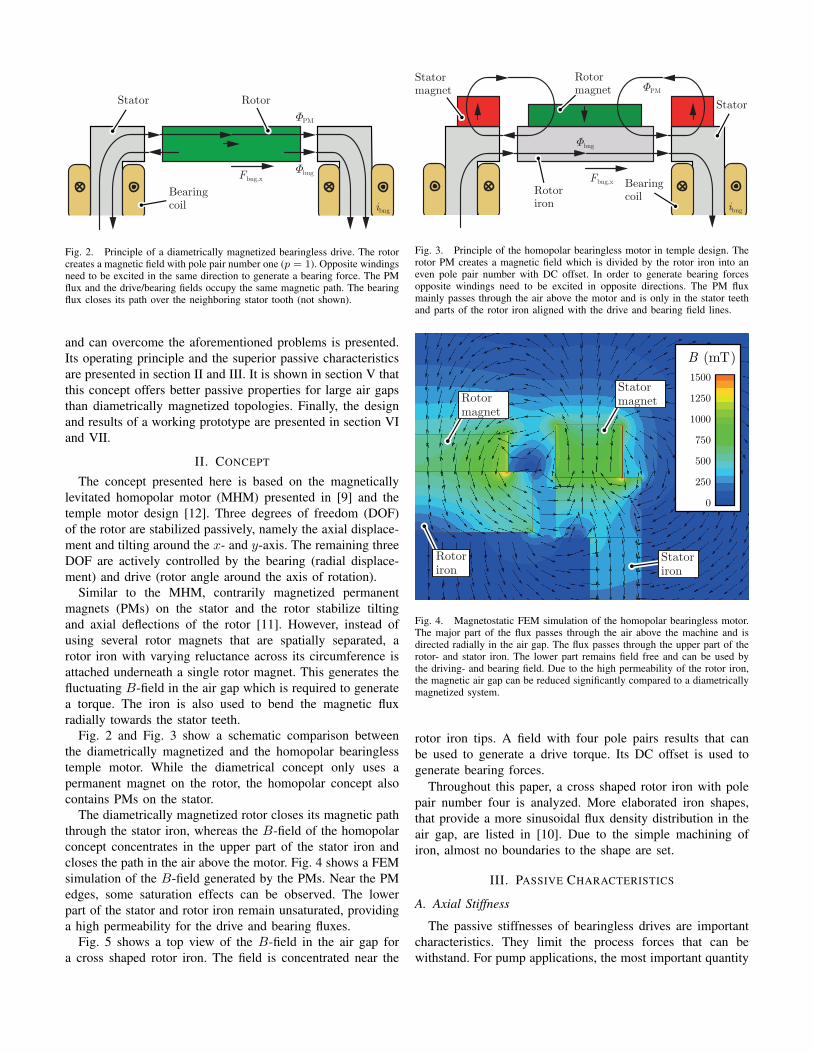
Fig. 2. Principle of a diametrically magnetized bearingless drive. The rotorcreates a magnetic field with pole pair number one (p = 1). Opposite windingsneed to be excited in the same direction to generate a bearing force. The PMflux and the drive/bearing fields occupy the same magnetic path. The bearingflux closes its path over the neighboring stator tooth (not shown).
and can overcome the aforementioned problems is presented.Its operating principle and the superior passive characteristicsare presented in section II and III. It is shown in section V thatthis concept offers better passive properties for large air gapsthan diametrically magnetized topologies. Finally, the designand results of a working prototype are presented in section VIand VII.
II. CONCEPT
The concept presented here is based on the magneticallylevitated homopolar motor (MHM) presented in [9] and thetemple motor design [12]. Three degrees of freedom (DOF)of the rotor are stabilized passively, namely the axial displace-ment and tilting around the x- and y-axis. The remaining threeDOF are actively controlled by the bearing (radial displace-ment) and drive (rotor angle around the axis of rotation).
Similar to the MHM, contrarily magnetized permanentmagnets (PMs) on the stator and the rotor stabilize tiltingand axial deflections of the rotor [11]. However, instead ofusing several rotor magnets that are spatially separated, arotor iron with varying reluctance across its circumference isattached underneath a single rotor magnet. This generates thefluctuating B-field in the air gap which is required to generatea torque. The iron is also used to bend the magnetic fluxradially towards the stator teeth.
Fig. 2 and Fig. 3 show a schematic comparison betweenthe diametrically magnetized and the homopolar bearinglesstemple motor. While the diametrical concept only uses apermanent magnet on the rotor, the homopolar concept alsocontains PMs on the stator.
The diametrically magnetized rotor closes its magnetic paththrough the stator iron, whereas the B-field of the homopolarconcept concentrates in the upper part of the stator iron andcloses the path in the air above the motor. Fig. 4 shows a FEMsimulation of the B-field generated by the PMs. Near the PMedges, some saturation effects can be observed. The lowerpart of the stator and rotor iron remain unsaturated, providinga high permeability for the drive and bearing fluxes.
Fig. 5 shows a top view of the B-field in the air gap fora cross shaped rotor iron. The field is concentrated near the
Fbng,x
ibng
Rotormagnet
Rotoriron
Bearingcoil
Statormagnet
Stator
Φbng
ΦPM
Fig. 3. Principle of the homopolar bearingless motor in temple design. Therotor PM creates a magnetic field which is divided by the rotor iron into aneven pole pair number with DC offset. In order to generate bearing forcesopposite windings need to be excited in opposite directions. The PM fluxmainly passes through the air above the motor and is only in the stator teethand parts of the rotor iron aligned with the drive and bearing field lines.
0
1500
1250
1000
750
500
250
B (mT)
Rotoriron
Statoriron
StatormagnetRotor
magnet
Fig. 4. Magnetostatic FEM simulation of the homopolar bearingless motor.The major part of the flux passes through the air above the machine and isdirected radially in the air gap. The flux passes through the upper part of therotor- and stator iron. The lower part remains field free and can be used bythe driving- and bearing field. Due to the high permeability of the rotor iron,the magnetic air gap can be reduced significantly compared to a diametricallymagnetized system.
rotor iron tips. A field with four pole pairs results that canbe used to generate a drive torque. Its DC offset is used togenerate bearing forces.
Throughout this paper, a cross shaped rotor iron with polepair number four is analyzed. More elaborated iron shapes,that provide a more sinusoidal flux density distribution in theair gap, are listed in [10]. Due to the simple machining ofiron, almost no boundaries to the shape are set.
III. PASSIVE CHARACTERISTICS
A. Axial Stiffness
The passive stiffnesses of bearingless drives are importantcharacteristics. They limit the process forces that can bewithstand. For pump applications, the most important quantity

B (mT)500
0
100
200
300
400
d
q
α
β
x
y
i1
i2
i3
i4
i5
i6
Fig. 5. Magnetostatic FEM simulation showing the top view of the air gapfield. Rotor iron (cross), rotor PM (circle), stator claws (squares) and statorPM (ring). The lower magnetic reluctance through the rotor iron concentratesthe air gap field near the rotor tips. For the illustrated topology, a magneticfield with pole pair number p = 4 and DC offset results.
is the axial stiffness kz as it limits the maximal pressure thatcan be handled.
It is defined as the change in axial force Fbng,z with respectto an axial displacement z of the rotor
kz = −dFbng,z
dz> 0. (1)
Fig. 6(a) shows a schematic drawing of the system in across sectional view. If the rotor is displaced in z-direction,the distance between the rotor and the stator is increased. Theresulting reluctance force Fbng,z attracts the rotor back to theequilibrium point.
B. Radial Stiffness
As described in [14], a positive axial stiffness results in adestabilizing radial stiffness, that is at least half as large inmagnitude
|kr| =∣∣∣∣dFr
dr
∣∣∣∣ > 1
2|kz| , (2)
where kr is the radial stiffness.As the radial stiffness destabilizes the rotor, it is favorable
to achieve low values of |kr|, such that the control loop of thebearing can be slower and disturbances have a lower impact.
Therefore, a good design is striving for a low ratio of|kr/kz|. As described in [14], the ratio is minimized to 1/2if solely permanent magnets are used. Considering the fluxpath of the PMs in this design, it becomes apparent thatthe magnetic field requires to penetrate a lot of air. As aconsequence, the ratio is expected to be better for the presentedconcept than for diametrically magnetized ones.
Fbng,z
z
(a)
Tdα
(b)
StatorRotoriron
Rotormagnet
Statormagnet
Fig. 6. Axial (a) and tilting displacements (b) of the rotor from itsequilibrium position. Reluctance forces Fbng,z and torques Td counteractthe rotor displacement.
C. Tilting Stiffness
The tilting stiffness of a bearingless motor is defined as thechange in restoring torque acting on the rotor due to a tilting ofthe rotor around any radial direction. It has to be distinguishedbetween rotations around the d- and the q-axis as illustratedin Fig. 5
kα = −dTddα
kβ = −dTqdβ
. (3)
Due to the concentration of the flux density at the rotor tips,the tilting stiffness around the d-axis kα is lower than kβ .
A schematic drawing of a tilted rotor is illustrated in Fig.6(b). Similar to the case of an axial displacement, the air gapis increased if the rotor tilts. The resulting reluctance forcescause the rotor to be pulled back to its center position.
For topologies exhibiting a slotted stator, these stiffnessesare functions of the rotor angle ϕ. The minimum value isof major interest as it is required to be positive for stableoperation. It is desirable to achieve a high tilting stiffness asthis will result in a system that tends less to a tilting movement.
It will be shown in a later section, that the tilting stiffnesscan be influenced largely by the height of the rotor PM.Though, it remains a trade-off between a high axial and tiltingstiffness.
IV. ACTIVE CHARACTERISTICS
A. Radial Bearing
As the rotor generates a biased magnetic field, bearingforces can be generated by strengthening the magnetic fieldin one direction and weakening it on the other side. Thiscauses the rotor to be attracted towards the side with higherflux density.
FxFy
TzTz(ib)
0 10 20 30 40 50 60 70 80 90-20
0
20
40
60
-100
0
100
200
300
Fx(ibng,y)Fy(ibng,y)
Tz(idrv,q)
Tz(ibng,y)
Rotor angle (°)
Torq
ue (
mN
m)
Bea
ring
forc
e (N
)
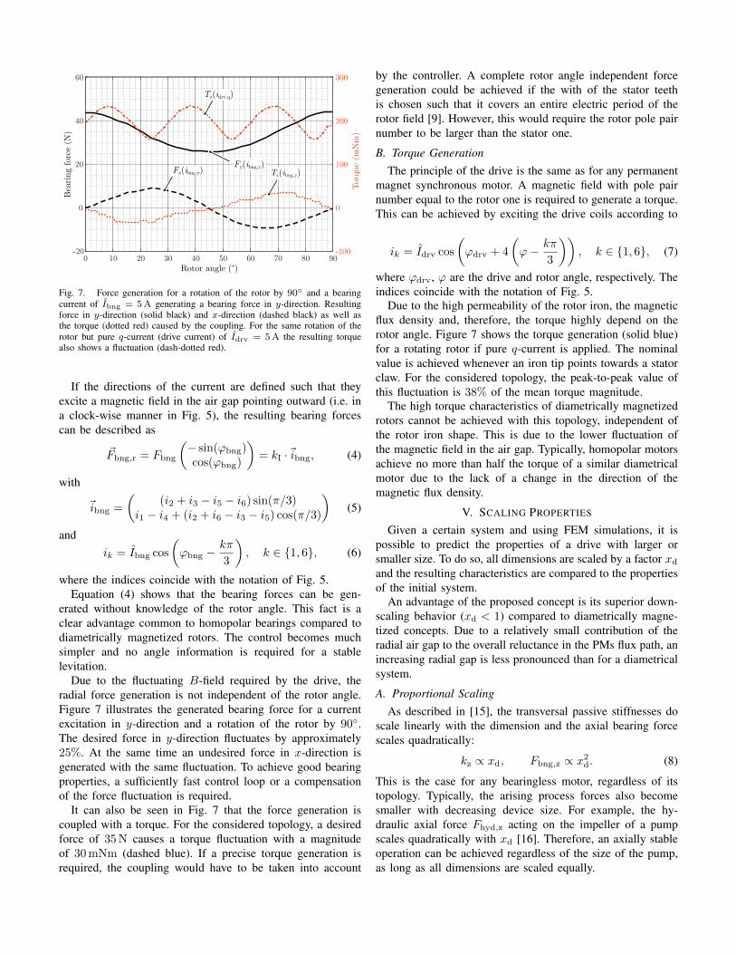
Fig. 7. Force generation for a rotation of the rotor by 90◦ and a bearingcurrent of Ibng = 5A generating a bearing force in y-direction. Resultingforce in y-direction (solid black) and x-direction (dashed black) as well asthe torque (dotted red) caused by the coupling. For the same rotation of therotor but pure q-current (drive current) of Idrv = 5A the resulting torquealso shows a fluctuation (dash-dotted red).
If the directions of the current are defined such that theyexcite a magnetic field in the air gap pointing outward (i.e. ina clock-wise manner in Fig. 5), the resulting bearing forcescan be described as
~Fbng,r = Fbng
(− sin(ϕbng)cos(ϕbng)
)= kI ·~ibng, (4)
with
~ibng =
((i2 + i3 − i5 − i6) sin(π/3)
i1 − i4 + (i2 + i6 − i3 − i5) cos(π/3)
)(5)
andik = Ibng cos
(ϕbng −
kπ
3
), k ∈ {1, 6}, (6)
where the indices coincide with the notation of Fig. 5.Equation (4) shows that the bearing forces can be gen-
erated without knowledge of the rotor angle. This fact is aclear advantage common to homopolar bearings compared todiametrically magnetized rotors. The control becomes muchsimpler and no angle information is required for a stablelevitation.
Due to the fluctuating B-field required by the drive, theradial force generation is not independent of the rotor angle.Figure 7 illustrates the generated bearing force for a currentexcitation in y-direction and a rotation of the rotor by 90◦.The desired force in y-direction fluctuates by approximately25%. At the same time an undesired force in x-direction isgenerated with the same fluctuation. To achieve good bearingproperties, a sufficiently fast control loop or a compensationof the force fluctuation is required.
It can also be seen in Fig. 7 that the force generation iscoupled with a torque. For the considered topology, a desiredforce of 35N causes a torque fluctuation with a magnitudeof 30mNm (dashed blue). If a precise torque generation isrequired, the coupling would have to be taken into account
by the controller. A complete rotor angle independent forcegeneration could be achieved if the with of the stator teethis chosen such that it covers an entire electric period of therotor field [9]. However, this would require the rotor pole pairnumber to be larger than the stator one.
B. Torque GenerationThe principle of the drive is the same as for any permanent
magnet synchronous motor. A magnetic field with pole pairnumber equal to the rotor one is required to generate a torque.This can be achieved by exciting the drive coils according to
ik = Idrv cos
(ϕdrv + 4
(ϕ− kπ
3
)), k ∈ {1, 6}, (7)
where ϕdrv, ϕ are the drive and rotor angle, respectively. Theindices coincide with the notation of Fig. 5.
Due to the high permeability of the rotor iron, the magneticflux density and, therefore, the torque highly depend on therotor angle. Figure 7 shows the torque generation (solid blue)for a rotating rotor if pure q-current is applied. The nominalvalue is achieved whenever an iron tip points towards a statorclaw. For the considered topology, the peak-to-peak value ofthis fluctuation is 38% of the mean torque magnitude.
The high torque characteristics of diametrically magnetizedrotors cannot be achieved with this topology, independent ofthe rotor iron shape. This is due to the lower fluctuation ofthe magnetic field in the air gap. Typically, homopolar motorsachieve no more than half the torque of a similar diametricalmotor due to the lack of a change in the direction of themagnetic flux density.
V. SCALING PROPERTIES
Given a certain system and using FEM simulations, it ispossible to predict the properties of a drive with larger orsmaller size. To do so, all dimensions are scaled by a factor xdand the resulting characteristics are compared to the propertiesof the initial system.
An advantage of the proposed concept is its superior down-scaling behavior (xd < 1) compared to diametrically magne-tized concepts. Due to a relatively small contribution of theradial air gap to the overall reluctance in the PMs flux path, anincreasing radial gap is less pronounced than for a diametricalsystem.
A. Proportional ScalingAs described in [15], the transversal passive stiffnesses do
scale linearly with the dimension and the axial bearing forcescales quadratically:
kz ∝ xd, Fbng,z ∝ x2d. (8)
This is the case for any bearingless motor, regardless of itstopology. Typically, the arising process forces also becomesmaller with decreasing device size. For example, the hy-draulic axial force Fhyd,z acting on the impeller of a pumpscales quadratically with xd [16]. Therefore, an axially stableoperation can be achieved regardless of the size of the pump,as long as all dimensions are scaled equally.

0.5 0.55 0.6 0.65 0.7 0.75 0.8 0.85 0.9 0.95 10.1
0.2
0.3
0.4
0.5
0.6
0.7
0.8
0.9
1
Nor
mal
ized
axi
al s
tiffn
ess k z
/kz0
Scaling factor xd
diametric δ = xdδ0
homopolar δ = xdδ0
diametric δ = δ0
homopolar δ = δ0
Fig. 8. Simulation of the change in axial stiffness of the two conceptswhen reducing the overall system size. Red: diametrically magnetized, blue:homopolar concept. Solid lines: variable air gap, dashed lines: constant airgap.
B. Scaling with Constant Air Gap
Problems arise if the air gap of a bearingless system mustretain a minimal length or shall be increased, e.g. in casea pump head requires a minimal wall thickness in order towithstand the pressure at the impeller outlet. The previouslypresented scaling laws are no longer valid. In such a case,the air gap length must be increased relative to the systemdimensions during down-scaling. Consequently, the magneticflux density in the radial gap decreases and the bearingstiffnesses drop more rapidly
∂kz∂xd
> 1. (9)
This in turn constrains the maximum process force thesystem can bear and consequently the operational range.
The rate ∂kz∂xd
at which the axial stiffness reduces whendown-scaling the system depends on the topology of themotor. FEM simulations were performed to verify that theproposed concept achieves lower values of ∂kz
∂xd. The results are
presented in Fig. 8. Compared to the diametrically magnetizedconcept, the loss in axial stiffness can be reduced for the casethat the air gap length is increased relative to the system size.Down-scaling by a factor of two while keeping the air gap atthe same length reduces the axial stiffness of the diametricallymagnetized system by 80%. For the presented homopolarmotor the axial stiffness is reduced by only 73%. Hence, thistopology is well suited for applications that require large airgaps and a high axial stiffness.
VI. PROTOTYPE
To proof the concept of the homopolar bearingless templemotor, a prototype was built by adjusting the stator of anexisting bearingless slice motor.
Rotormagnet
Rotoriron
Protectivealuminumring
Fig. 9. Assembly of the rotor consisting of an axially magnetized magnet(top), cross-shaped rotor iron (center bottom) and an aluminum ring to protectthe stator.
A. Rotor
An axially magnetized NdFeB PM with diameterDpm = 60mm was used for the rotor. A cross-shapedrotor iron is attached below the PM, as illustrated in Fig. 9, toguide the flux with pole pair number p = 4 radially towardsthe stator teeth. The diameter of the rotor iron was chosenequal to the rotor diameter of the diametrically magnetizedreference rotor, to achieve comparability.
Fig. 10 shows the axial and tilting stiffnesses as a functionof the rotor PM height with otherwise constant parameters.Both stiffnesses achieve a clear maximum. The maximal axialstiffness is achieved for a magnet height of 17mm. However,for such a high rotor, the system becomes unstable in tiltingdirection as indicated by the dashed red line. The maximumtilting stiffness on is achieved when the axial stiffness iscomparatively low. For the prototype, a rotor PM height ofHpm = 10mm was chosen as a trade-off for a simultaneouslyhigh axial and tilting stiffness.
To protect the stator from destruction in case the rotorbecomes unstable and touches the stator wall, the iron crosswas covered by an aluminum ring.
B. Stator
A stator in temple design with six stator claws wasused. A ring shaped NdFeB magnet with outer diameterDout = 110mm, inner diameter Din = 75mm and heightH = 14mm was mounted on top of the stator to achieve ahigh axial stiffness and a similar radial stiffness as the diamet-rically magnetized rotor used as a reference. A photograph ofthe assembled prototype is shown in Fig. 11.
The bearing and drive coils were each realized using a threephase system with floating star point. The supplying dc voltagewas 325V. Windings on opposite sides where connected inseries but with different winding orientation for bearing anddrive.
VII. RESULTS
A summary of the motor properties and a comparison to adiametrically magnetized system is given in Table I

20
40
0
0.2
Tilt
ing
stiff
ness
kα (N
m/°
)
Axi
al s
tiffn
ess k
z (N
/mm
)
0.1
-0.110
30
selecteddesign
5 10 15 20Rotor magnet height HPM (mm)
Fig. 10. Axial (blue) and tilting stiffness (red) as a function of the rotor PMheight. The dashed part indicates the unstable region. The design parameterselected for the prototype is marked by the vertical dashed line.
A. Axial Stiffness
The prototype achieved an axial stiffness ofkz = 23.9N/mm. Measurements coincide well with thesimulation results kz,sim = 23.2N/mm. Compared to adiametrically magnetized rotor with similar dimensions(kz = 7.2N/mm) the axial stiffness could be increased by afactor of 3.3.
B. Radial Stiffness
The prototype was designed such that it achieves the sameradial stiffness as a diametrically magnetized motor. As aresult, the radial stiffness remains nearly unchanged and iskr = −24.9N/mm.
As expected, the ratio |kr/kz| could be reduced by morethan a factor of 3 from 3.6 to 1.04. This is due to the muchhigher reluctance in the flux path of the PM above the motorand the lower amount of permeable material.
C. Tilting Stiffness
At the same time the tilting stiffness was increasedfrom kα = 81mNm/◦ and kβ = 33.4mNm/◦ tokα = 211mNm/◦ and kβ = 175mNm/◦, respectively.
For the weak tilting axis, this is an increase by a factor of5.2. Due to the higher pole pair number, the tilting stiffnesswas also homogenized. Therefore, the rotor has a lowertendency to tilt along a certain axis.
D. Torque
As a consequence of the biased air gap field, the torquecapacity drops significantly. Compared to the diametricallymagnetized rotor, the peak to peak value of the radial B-fieldin the air gap was reduced from 1.6T to 0.25T. However,due to the much lower reluctance, the torque constant kT onlyreduces by a factor of 3.5.
Furthermore, the prototype was successfully operated up to5000 rpm in air and could also be operated as a pump.
Statormagnet
Rotormagnet
Fig. 11. Assembled prototype with levitating rotor. The stator magnet ring(white) can simply be added to the stator.
TABLE ICOMPARISON OF THE CHARACTERISTICS
Parameter Homopolar Diametrical Unitaxial stiffness, kz 23.9 7.2 N/mmradial stiffness, kr -24.9 -25.9 N/mmratio |kr/kz| 1.04 3.6 −tilting stiffness around d, kα 175 33.4 mNm/◦
tilting stiffness around q, kβ 211 81 mNm/◦
ratio∣∣kα/kβ∣∣ 0.83 0.41 −
torque constant, kT 34 120 mNm/A
torque at Idrv = 5A, Tsat 0.15 0.6 Nm
VIII. CONCLUSION
Based on the principle of the magnetically levitated ho-mopolar motor [9] and the temple topology [12] a novel ho-mopolar bearingless drive was developed. The motor consistsof oppositely magnetized permanent magnets on the rotor andstator side. The axial and tilting movements are stabilizedpassively by means of repelling reluctance forces. A cross-shaped iron was attached below the permanent magnet ofthe rotor to guide the flux density towards the stator teeth.A varying reluctance along its circumference generates theperiodic fluctuation required by the drive.
Using FEM simulations it was shown that this concept canachieve a higher axial stiffness than a comparable diametri-cally magnetized system. To proof the concept, a prototypewas built and tested successfully. Compared to a diametricallymagnetized rotor the axial stiffness could be increased by afactor of 3.3, while keeping the radial stiffness unchanged.Also, the tilting stiffness could be increased by at least a factorof 2.5. The major drawbacks are its low torque capability,high torque and force ripples and the required total permanentmagnet volume.
It was simulated that the new concept is superior if aminimal air gap length needs to be maintained.Therefore, thistopology fits best for applications with a large air gap and highprocess forces but lower torque requirements.
REFERENCES
[1] J. Bichsel, “The bearingless electrical machine,” in Proc. ISMST.NASA, Langley Research Center, May 1992, pp. 561–573.
[2] A. Chiba, D. T. Power, and M. A. Rahman, “Characteristics of abearingless induction motor,” IEEE Transactions on Magnetics, vol. 27,no. 6, pp. 5199–5201, Nov 1991.
[3] R. Schoeb and N. Barletta, “Magnetic bearing. principle and applicationof a bearingless slice motor.” JSME International Journal Series CMechanical Systems, Machine Elements and Manufacturing, vol. 40,no. 4, pp. 593–598, 1997.
[4] J. Asama, D. Kanehara, T. Oiwa, and A. Chiba, “Development of a com-pact centrifugal pump with a two-axis actively positioned consequent-pole bearingless motor,” IEEE Transactions on Industry Applications,vol. 50, no. 1, pp. 288–295, 2014.
[5] M. Neff, N. Barletta, and R. Schoeb, “Bearingless centrifugal pump forhighly pure chemicals,” in Proc. 8th ISMB, 2002, pp. 283–287.
[6] R. Baumschlager, R. Schoeb, and J. Schmied, “Bearingless hydrogenblower,” in Proc. on 8th ISMB Int. Symposium on Magnetic Bearings,2002.
[7] H. M. Loree, K. Bourque, D. B. Gernes, J. S. Richardson, V. L. Poirier,N. Barletta, A. Fleischli, G. Foiera, T. M. Gempp, R. Schoeb et al.,“The heartmate iii: design and in vivo studies of a maglev centrifugalleft ventricular assist device,” Artificial organs, vol. 25, no. 5, pp. 386–391, 2001.
[8] J. Asama, T. Fukao, A. Chiba, A. Rahman, and T. Oiwa, “A designconsideration of a novel bearingless disk motor for artificial hearts,” in2009 IEEE Energy Conversion Congress and Exposition. IEEE, 2009,pp. 1693–1699.
[9] T. Schneeberger, T. Nussbaumer, and J. W. Kolar, “Magnetically lev-itated homopolar hollow-shaft motor,” IEEE/ASME Transactions onMechatronics, vol. 15, no. 1, pp. 97–107, 2010.
[10] R. Schoeb, “Magnetically journalled rotational arrangement including arotor for generating a unipolar bias magnetic flux,” U.S. Patent 7,112,903B1, Sep 26, 2006.
[11] T. Nussbaumer, P. Karutz, F. Zurcher, and J. W. Kolar, “Magneticallylevitated slice motors - an overview,” IEEE Transactions on IndustryApplications, vol. 47, no. 2, pp. 754–766, 2011.
[12] N. Barletta and R. Schoeb, “Design of a bearingless blood pump,” 1996.[13] W. Gruber, M. Rothbock, and R. T. Schoeb, “Design of a novel homopo-
lar bearingless slice motor with reluctance rotor,” IEEE Transactions onIndustry Applications, vol. 51, no. 2, pp. 1456–1464, 2015.
[14] J.-P. Yonnet, “Permanent magnet bearings and couplings,” IEEE Trans-actions on Magnetics, vol. 17, no. 1, pp. 1169–1173, 1981.
[15] D. Steinert, T. Nussbaumer, and J. W. Kolar, “Concept of a 150 krpmbearingless slotless disc drive with combined windings,” in ElectricMachines & Drives Conference (IEMDC), 2013 IEEE International.IEEE, 2013, pp. 311–318.
[16] H. M. Badr and W. H. Ahmed, Pumping Machinery Theory andPractice. John Wiley & Sons Ltd, 2014, ch. Axial and Radial Thrustsin Centrifugal Pumps, pp. 133–158.