
HOMOGENIZATION OF LIQUID DISTRIBUSTION IN … · Homogeneous combustion may be defined as a process...
8
ILASS 2008 Sep. 8-10, 2008, Como Lake, Italy 1. INTRODUCTION One of the main future tasks for Diesel engine development is de-coupling of combustion process from injection process. On one hand side, important is separation of both processes in time, and on the another hand side required is homogenization of the charge (by injection) in the combustion chamber volume (Fig.1). Figure 1. The need of charge homogenization in both gasoline and Diesel engines The engine combustion process is determined by the parameters of cylinder charge: by the air-to-fuel ratio (mixture composition) and homogeneity of the charge (mixture structure) and by the type of ignition. Mixture composition together with mixture structure and kind of ignition defines combustion mode in the internal-combustion engine HOMOGENIZATION OF LIQUID DISTRIBUSTION IN SPACE BY DIESEL JET INTERACTION WITH POROUS STRUCTURES AND SMALL OBSTACLES M. Weclas Georg Simon Ohm University of Applied Sciences Nuremberg Georg-Simon-Ohm-Hochschule Nürnberg, Fakultät Maschinenbau Institut für Fahrzeugtechnik (IFZN) Kesslerplatz 12, D-90489 Nürnberg Email: [email protected] ABSTRACT One of the main future tasks for Diesel engine development is de-coupling of combustion process from injection process. On one hand side, important is separation of both processes in time, and on the another hand side required is homogenization of the charge (by injection) in the combustion chamber volume. By late injection process, typical for conventional Diesel engine, a high injection pressure and short injection duration must be used for permitting proper temporal mixture formation, however, this mixture is highly non-homogeneous in space. Typical technologies applied to conventional engine combustion systems to support fuel distribution in the chamber volume are intense swirl and squish air motions and multi-hole nozzles, as well as different strategies for fuel injection timing. The paper presents results of experimental investigations of common-rail Diesel jet impingement on highly porous, open cell structures as well as on small cylindrical obstacles. A model describing characteristic phases of Diesel jet interaction with a porous structure is presented in the article. The paper deals also with ‘destroying’ a high-velocity diesel fuel jet by impingement on small cylindrical obstacles. This process permits very quick jet distribution in the volume. Essential is a process of impingement on a first obstacle: its diameter, distance from the nozzle outlet, and injection pressure play a dominant role in characterizing jet distribution in space. indirect Injection (pre-chamber) Direct Injection >>1 High injection pressure High pressure charging Partial Homogenization of charge (low load) Compression ignition indirect Injection (port injection) Direct Injection Non- homogeneous >1 Non- homogeneous >>1 Homogenization of charge (load=var) Spark-plug ignition Homogeneous Charge =1 Homogeneous Charge =1 Direct Injection Stratified Charge >>1 High pressure charging „down-sizing“ Compression Ignition (low load) Volumetric Ignition (load=var) „power density“ Compression ignition Compression ignition Homogeneous charge Homogeneous charge Reduced compression ratio Higher compression ratio HCCI Gasoline Diesel Paper ID ILASS08-6-7 1
Transcript of HOMOGENIZATION OF LIQUID DISTRIBUSTION IN … · Homogeneous combustion may be defined as a process...
ILASS 2008
Sep. 8-10, 2008, Como Lake, Italy
Paper ID ILASS08-A003
1. INTRODUCTION
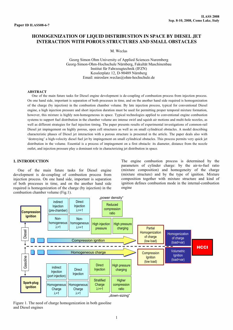
One of the main future tasks for Diesel engine development is de-coupling of combustion process from injection process. On one hand side, important is separation of both processes in time, and on the another hand side required is homogenization of the charge (by injection) in the combustion chamber volume (Fig.1).
Figure 1. The need of charge homogenization in both gasoline and Diesel engines
The engine combustion process is determined by the parameters of cylinder charge: by the air-to-fuel ratio (mixture composition) and homogeneity of the charge (mixture structure) and by the type of ignition. Mixture composition together with mixture structure and kind of ignition defines combustion mode in the internal-combustion engine
HOMOGENIZATION OF LIQUID DISTRIBUSTION IN SPACE BY DIESEL JET INTERACTION WITH POROUS STRUCTURES AND SMALL OBSTACLES
M. Weclas
Georg Simon Ohm University of Applied Sciences Nuremberg Georg-Simon-Ohm-Hochschule Nürnberg, Fakultät Maschinenbau
Institut für Fahrzeugtechnik (IFZN) Kesslerplatz 12, D-90489 Nürnberg
Email: [email protected]
ABSTRACTOne of the main future tasks for Diesel engine development is de-coupling of combustion process from injection process.
On one hand side, important is separation of both processes in time, and on the another hand side required is homogenization
of the charge (by injection) in the combustion chamber volume. By late injection process, typical for conventional Diesel
engine, a high injection pressure and short injection duration must be used for permitting proper temporal mixture formation,
however, this mixture is highly non-homogeneous in space. Typical technologies applied to conventional engine combustion
systems to support fuel distribution in the chamber volume are intense swirl and squish air motions and multi-hole nozzles, as
well as different strategies for fuel injection timing. The paper presents results of experimental investigations of common-rail
Diesel jet impingement on highly porous, open cell structures as well as on small cylindrical obstacles. A model describing
characteristic phases of Diesel jet interaction with a porous structure is presented in the article. The paper deals also with
‘destroying’ a high-velocity diesel fuel jet by impingement on small cylindrical obstacles. This process permits very quick jet
distribution in the volume. Essential is a process of impingement on a first obstacle: its diameter, distance from the nozzle
outlet, and injection pressure play a dominant role in characterizing jet distribution in space.
indirect
Injection
(pre-chamber)
Direct
Injection
>>1
High injection
pressure
High pressure
charging Partial
Homogenization
of charge
(low load)
Compression
ignition
indirect
Injection
(port injection)
Direct
Injection
Non-
homogeneous
>1
Non-
homogeneous
>>1
Homogenization
of charge
(load=var)
Spark-plug
ignitionHomogeneous
Charge
=1
Homogeneous
Charge
=1
Direct
Injection
Stratified
Charge
>>1
High pressure
charging
„down-sizing“
Compression
Ignition
(low load)
Volumetric
Ignition
(load=var)
„power density“
Compression ignitionCompression ignition
Homogeneous chargeHomogeneous charge
Reduced
compression
ratio
Higher
compression
ratio
HCCI
Gas
olin
eD
iese
lPaper ID ILASS08-6-7
1
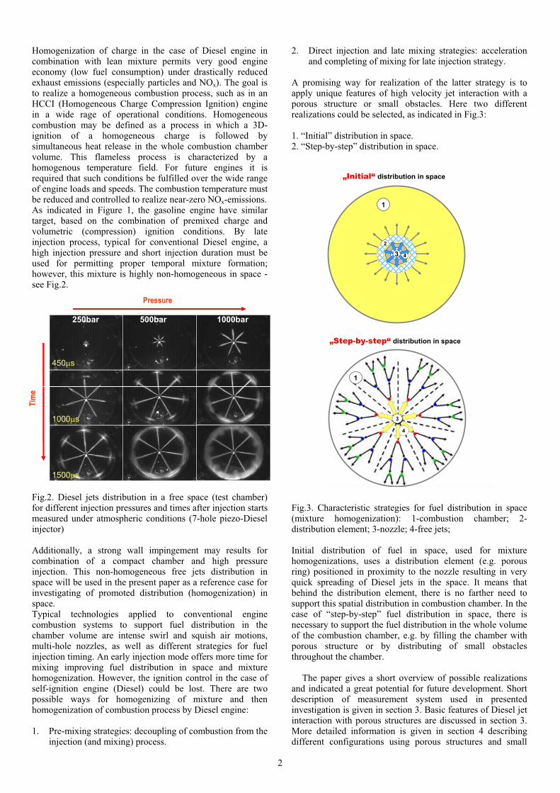
Homogenization of charge in the case of Diesel engine in combination with lean mixture permits very good engine economy (low fuel consumption) under drastically reduced exhaust emissions (especially particles and NOx). The goal is to realize a homogeneous combustion process, such as in an HCCI (Homogeneous Charge Compression Ignition) engine in a wide rage of operational conditions. Homogeneous combustion may be defined as a process in which a 3D-ignition of a homogeneous charge is followed by simultaneous heat release in the whole combustion chamber volume. This flameless process is characterized by a homogenous temperature field. For future engines it is required that such conditions be fulfilled over the wide range of engine loads and speeds. The combustion temperature must be reduced and controlled to realize near-zero NOx-emissions. As indicated in Figure 1, the gasoline engine have similar target, based on the combination of premixed charge and volumetric (compression) ignition conditions. By late injection process, typical for conventional Diesel engine, a high injection pressure and short injection duration must be used for permitting proper temporal mixture formation; however, this mixture is highly non-homogeneous in space - see Fig.2.
Fig.2. Diesel jets distribution in a free space (test chamber) for different injection pressures and times after injection starts measured under atmospheric conditions (7-hole piezo-Diesel injector)
Additionally, a strong wall impingement may results for combination of a compact chamber and high pressure injection. This non-homogeneous free jets distribution in space will be used in the present paper as a reference case for investigating of promoted distribution (homogenization) in space.Typical technologies applied to conventional engine combustion systems to support fuel distribution in the chamber volume are intense swirl and squish air motions, multi-hole nozzles, as well as different strategies for fuel injection timing. An early injection mode offers more time for mixing improving fuel distribution in space and mixture homogenization. However, the ignition control in the case of self-ignition engine (Diesel) could be lost. There are two possible ways for homogenizing of mixture and then homogenization of combustion process by Diesel engine:
1. Pre-mixing strategies: decoupling of combustion from the injection (and mixing) process.
2. Direct injection and late mixing strategies: acceleration and completing of mixing for late injection strategy.
A promising way for realization of the latter strategy is to apply unique features of high velocity jet interaction with a porous structure or small obstacles. Here two different realizations could be selected, as indicated in Fig.3:
1. “Initial” distribution in space. 2. “Step-by-step” distribution in space.
Fig.3. Characteristic strategies for fuel distribution in space (mixture homogenization): 1-combustion chamber; 2-distribution element; 3-nozzle; 4-free jets;
Initial distribution of fuel in space, used for mixture homogenizations, uses a distribution element (e.g. porous ring) positioned in proximity to the nozzle resulting in very quick spreading of Diesel jets in the space. It means that behind the distribution element, there is no farther need to support this spatial distribution in combustion chamber. In the case of “step-by-step” fuel distribution in space, there is necessary to support the fuel distribution in the whole volume of the combustion chamber, e.g. by filling the chamber with porous structure or by distributing of small obstacles throughout the chamber.
The paper gives a short overview of possible realizations and indicated a great potential for future development. Short description of measurement system used in presented investigation is given in section 3. Basic features of Diesel jet interaction with porous structures are discussed in section 3. More detailed information is given in section 4 describing different configurations using porous structures and small
1
3
1
3
2
„Initial“ distribution in space
4
„Step-by-step“ distribution in space
4
Pressure
Tim
e
250bar 500bar 1000bar
450 s
1000 s
1500 s
2

cylindrical obstacles: 1- Initial spreading of jets by interaction with porous ring and distribution in a free volume; 2- Initial spreading of jets by interaction with porous ring and distribution in a porous medium volume; 3- Initial spreading of jets by interaction with small obstacles. These configurations are compared to Diesel (free) jets in a free space of the combustion chamber. General comments on Diesel jet interaction with porous structures and small obstacles are formulated in section 5.
2. MEASUREMENT TECHNIQUE
In order to investigate Diesel jet interaction with a porous structure and small obstacles, a special low-pressure test chamber has been used with two different surrounding fluids (air or oil)- see Fig.4. Diesel injection in oil has some special features: no atomization may be observed during free jet formation and its propagation throughout the chamber volume (single-phase system in liquid); any fuel vaporization process is practically eliminated. For taking measurements at high resolutions with respect to time, a black-and-white CDD camera with an external trigger (synchronized with injection
timing) and with shutter speeds from 1 to 1000 s has been used. In the investigations reported here, an exposure time
between 10 s and 100 s has been applied. Additionally, the signal phase could be shifted with respect to the injector trigger signal. A detailed description of the system is given in [3,4].
Fig.4. View of the test rig used in reported investigation
3. BASIC FEATURES OF DIESEL JET INTERACTION WITH A POROUS STRUCTURE
The paper presents results of experimental investigations of common-rail Diesel jet impingement on highly porous, open cell structures as well as on small cylindrical obstacles. Porous structures considered in this paper are characterized by a high porosity (over 80%), open cells, large specific surface area, large heat capacity, excellent heat transfer as well as mechanical and thermal stability. A model describing characteristic phases of Diesel jet interaction with a porous structure is presented in the article.
In order to specify the very unique features of jet interaction with a porous medium, the impingement process has been compared to the process of jet impingement on the
solid wall, as already described in [1-4]. There are four characteristic phases of liquid-jet interaction with the (cold) porous medium which are highlighted in this paper (Fig.5):
Fig.5. Characteristic phases of Diesel jet interaction with a highly porous structure
Phase A: In a free space between nozzle outlet and porous medium surface, a free jet penetrates throughout the available space defined by the distance between nozzle and PM until impinging onto the PM surface. A free jet in Phase A is characterized by the jet angle, its velocity and propagation angle with respect to the PM surface. Depending on the distance from PM, a free jet may partly or fully be developed in space.
Phase B: The jet impingement onto the PM-surface may be divided into two parts: jet reflection from the interface (phase B) and jet propagation throughout (inside) the PM-volume (phase C). This division between phases B and C depend on the injection parameters, nozzle geometry, distance from the nozzle outlet as well as on the pore size, its density and the wall thickness of the pore junctions.
Phase C: In this phase the jet is distributed (propagates) throughout the PM-volume, and this process is characterized by a wide jet spreading (“self-homogenization”) in the PM-volume. This effect is related to a multi jet splitting [1-4]. The multi-jet splitting is a result of jet interaction with a large number of pore junctions (walls) present in the PM-volume.
Phase D: Depending on the jet momentum, impingement velocity, PM geometry, pore size and density, the injected fuel is completely trapped inside the porous medium volume or part of the liquid may leave the PM-volume (Phase D) -see fig.5. This effect may be utilized for different applications in internal combustion engines, as presented below.
As indicated in fig.6, the axial jet propagation inside the porous structure is reduced, and rapid radial fuel distribution may be observed giving rise to a very quick homogenization effect in space.
3
t=100 s t=300 st=500 s
Diesel nozzle
3D-porous structureDiesel jet
Phase A Phase B Phase C
Phase D
Fig.6. Example of a single Diesel jet interaction with a highly porous structure at three instances after Diesel jet contacts the porous structure
4. DIFFERENT CONCEPTS FOR UTILIZATION OF DIESEL JET INTERACTION WITH A POROUS STRUCTURE FOR SUPPORTING OF MIXTURE HOMOGENIZATION IN SPACE
There are different concepts utilizing an interaction of a high-velocity liquid jet (e.g. Diesel or gasoline spray) with a highly porous structure (see Fig.3). The author wants to give a general description indicating a great potential of this new technique, rather than to perform very detail analysis of a particular system.
1. Initial spreading of jets by interaction with porous
ring and distribution in a free volume
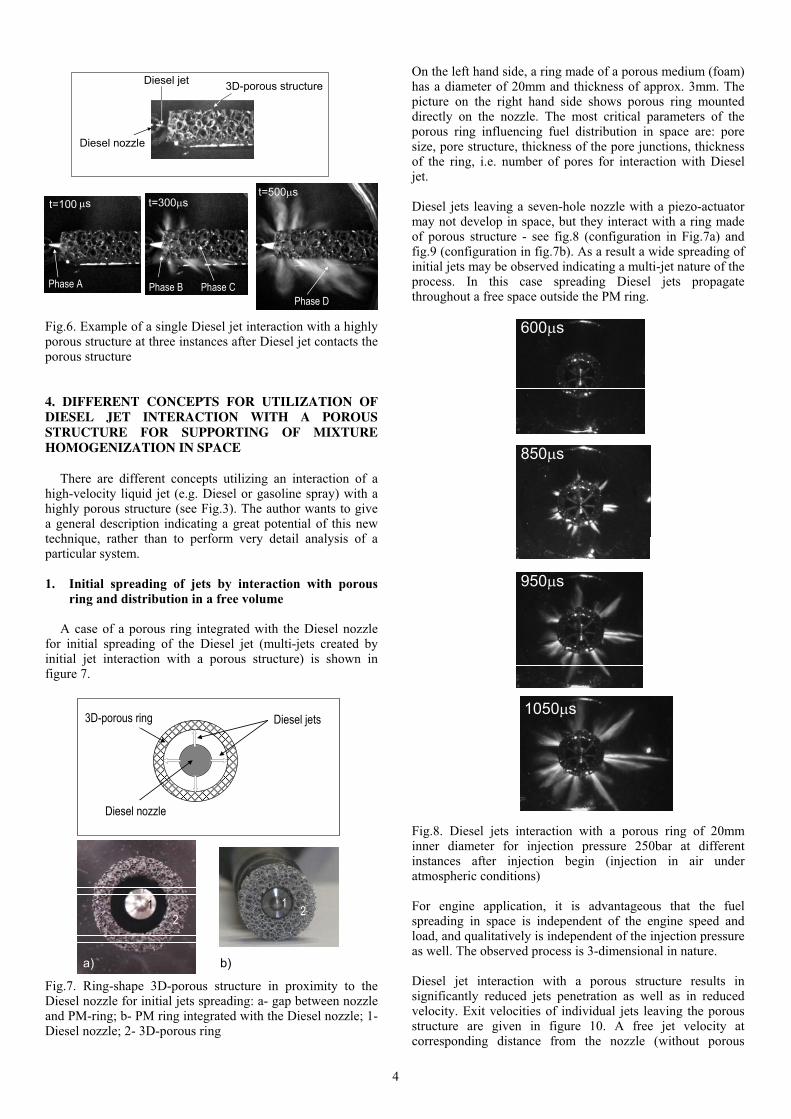
A case of a porous ring integrated with the Diesel nozzle for initial spreading of the Diesel jet (multi-jets created by initial jet interaction with a porous structure) is shown in figure 7.
Fig.7. Ring-shape 3D-porous structure in proximity to the Diesel nozzle for initial jets spreading: a- gap between nozzle and PM-ring; b- PM ring integrated with the Diesel nozzle; 1-Diesel nozzle; 2- 3D-porous ring
On the left hand side, a ring made of a porous medium (foam) has a diameter of 20mm and thickness of approx. 3mm. The picture on the right hand side shows porous ring mounted directly on the nozzle. The most critical parameters of the porous ring influencing fuel distribution in space are: pore size, pore structure, thickness of the pore junctions, thickness of the ring, i.e. number of pores for interaction with Diesel jet.
Diesel jets leaving a seven-hole nozzle with a piezo-actuator may not develop in space, but they interact with a ring made of porous structure - see fig.8 (configuration in Fig.7a) and fig.9 (configuration in fig.7b). As a result a wide spreading of initial jets may be observed indicating a multi-jet nature of the process. In this case spreading Diesel jets propagate throughout a free space outside the PM ring.
Fig.8. Diesel jets interaction with a porous ring of 20mm inner diameter for injection pressure 250bar at different instances after injection begin (injection in air under atmospheric conditions)
For engine application, it is advantageous that the fuel spreading in space is independent of the engine speed and load, and qualitatively is independent of the injection pressure as well. The observed process is 3-dimensional in nature.
Diesel jet interaction with a porous structure results in significantly reduced jets penetration as well as in reduced velocity. Exit velocities of individual jets leaving the porous structure are given in figure 10. A free jet velocity at corresponding distance from the nozzle (without porous
Diesel nozzle
3D-porous ring Diesel jets
a) b)
1 1
22
600 s
850 s
950 s
1050 s
4

structure) is: 145m/s for 500bar, and 210m/s for 1000bar. After interaction with a porous ring the presented in figure 10 velocities are on the order of 40 to 60m/s, and for 1000bar on the order of 70 to 100m/s. Exceptions are individual jets which have been not significantly influences by porous structure. Please indicate that the porous ring thickness in configuration of fig. 7 is on the order of two to three pores, only.
Fig.9. Diesel jets interaction with a porous ring of 7mm inner diameter and thickness of 5mm (20ppi) for three injection pressures 300,600 and 900bar at different instances after injection begin (injection in oil under atmospheric conditions)
2. Initial spreading of jets by interaction with porous
ring and distribution in a porous medium volume
A novel clean-engine concept which uses a porous medium reactor for realization of a homogeneous and flameless combustion process has been described in [5]. In this case the porous reactor should support two different processes: fuel distribution (homogenization) in space by direct Diesel injection and combustion process (homogeneous in space) itself. Both functions of the porous reactor require different pore size to make both processes optimum. One of promising way to resolve this problem is to divide these functions in two different systems: porous ring having small pore size integrated with the nozzle for promoting spatial distribution of fuel, and porous reactor having large pore size for realization of combustion process. A case of a porous ring integrated with a porous medium reactor volume for initial spreading of the Diesel jet (multi-jets created by initial jet interaction with a porous structure- (see fig.12) is shown in figure 11.
Fig.10. Secondary jets leaving the porous structure (acc. to multi-jet splitting effect): table shows the jets leaving velocity
Fig.11. Ring-shape 3D-porous structure in proximity to the Diesel nozzle integrated with a porous medium reactor: 1-Diesel nozzle; 2-3D-porous ring, 3- porous medium reactor (for combustion)
Different investigation configurations with a 7-hole piezo-CR-Diesel nozzle are presented in figure 11. The data are
Diesel nozzle
3D-porous ringDiesel jets
12
Porous medium
reactor
3
Druck
Zeitpunkt
Jetnummer
1
2
3
4
5
6
7
8
9
10
11
12
13
p = 500bar
t = 650µs
v in [m/s]
62,8
31,8
79,9
30,4
40,7
41,6
35,6
67,6
51,7
37,3
83,7
63,3
35,1
Druck
Zeitpunkt
Jetnummer
1
2
3
4
5
6
7
8
9
10
11
12
13
109,3
71,1
74,7
72,5
63,0
67,8
111,7
p = 1000bar
t = 550µs
v in [m/s]
91,5
67,5
114,3
159,0
123,4
67,0
Druck
Zeitpunkt
Jetnummer
1
2
3
4
5
6
7
8
9
10
11
12
13
p = 500bar
t = 650µs
v in [m/s]
62,8
31,8
79,9
30,4
40,7
41,6
35,6
67,6
51,7
37,3
83,7
63,3
35,1
Druck
Zeitpunkt
Jetnummer
1
2
3
4
5
6
7
8
9
10
11
12
13
109,3
71,1
74,7
72,5
63,0
67,8
111,7
p = 1000bar
t = 550µs
v in [m/s]
91,5
67,5
114,3
159,0
123,4
67,0
tPressure
Time instancep=500 bart=650 s
Pressure
Jet velocity
p=1000 bart=550 s
Number Number
Time instance
Jet velocity
8
910
1
2 3
4
6
7
511
12
13
500 s
900 s
1300 s
1700 s
2000 s
700 s
900 s
1100 s
1300 s
400 s
600 s
800 s
1000 s
300bar 600bar 900bar
5

presented at a single instant of 1200 s after injection begins and injection pressure 500bar in air at atmospheric conditions. A comparison concerns resulting jets distribution in space.
Fig.12. Different investigated configurations and comparison of resulting jets distribution (7-hole piezo-CR-Diesel nozzle)
in space at a single instant of 1200 s after injection begin and injection pressure 500bar in air at atmospheric conditions
In Fig. 12a Diesel nozzle in a free space is presented with a significant wall impingement at investigated time instance. This configuration is then modified with a small porous ring (see fig.7) and a strong multi-jet splitting may be observed in fig.12b improving the spatial distribution in space.
Fig.13. Multi-jet splitting effect of Diesel jet interaction with porous structures (top) as compared to a free Diesel jets (bottom)
As indicated in figure 13, Diesel jet interaction with a porous structure results in a multi-jet splitting of impinging jet making very strong spreading of the secondary jets in space. Configuration of fig.12c consists of a porous reactor having large pores. There a strong fuel distribution throughout the
porous medium volume may be observed. The last picture (fig.12d) combines the last two configurations.
3. Initial spreading of jets by interaction with small
obstacles
A similar effect may be obtained by a Diesel jet interaction with small cylindrical obstacles, as shown in figure 14. In this case small obstacles simulate wall junctions of a 3D-porous structure.
Fig.14. Multi-jet splitting effect of Diesel jet interaction with small obstacles: a-on overall idea; b-Diesel jet interaction with a one-single obstacle; b-Diesel jet interaction with 5-obstacles (results obtained for a single jet in oil)
For the fuel spreading in space not a number of obstacles but their geometrical configuration is critical. The cases presented
wallnozzle
porous ring porous
reactor
porous
reactor
nozzle nozzle nozzle
porous ring
1200 s
500bar
a) b) c) d)
Diesel nozzle
Free jets
Multi-jet splitting
Porous ring
Diesel nozzle
Diesel injector
Diesel nozzle
Single obstacle
Diesel nozzle
5-obstacles
Diesel nozzle
a)
b)
c)
Small obstacles
6

in Fig.14 consists of a one-single obstacle (fig.14b) and of 5 obstacles (fig.14c) resulting in very good Diesel-jet distribution in space (presented is a single Diesel jet). The dominant role in this process is played by a first obstacle: its diameter, distance from the nozzle outlet and the injection pressure (impingement velocity) are major factors (parameters) of jet distribution in space. This distribution is based on a multi-jet splitting model [3].
For diesel jet impingement on more than one single obstacle (per jet), jet distribution depends on the obstacle’s geometrical configuration but not necessarily on the number of obstacles. Quite similar distribution could be obtained for configurations with four and eight obstacles- see Fig.15.
Fig.15. Model of Diesel jet interaction with small obstacles
The spatial distribution of Diesel jets interacting with small obstacles is characterized by distribution angles, as indicated in Table 1.
Table.1. Distribution angles , 1, 2 for Diesel jet interaction with a single- and three-obstacles (data for injection in oil)
The angle does not change with time after impingement process, but decreases with increasing distance between nozzle and obstacle. If the obstacle size or distance from the nozzle is not properly adjusted, it may happen that the angle
is too large promoting formation (merging) of secondary jets after impingement process, as shown in Fig.16.
Fig.16. Merging of individual jets after impingement on
cylindrical obstacles observed when distribution angle is too large (obstacle diameter is too large for investigated Diesel jet size)
230
51.40
34.80
18 0
Diesel
jet
3-obstacles
4-obstacles
8-obstacles
2
1
61,81-obstacle: p = 1200 bar, t = 800 µs
70,81-obstacle: p = 800 bar, t = 800 µs
93,21-obstacle: p = 400 bar, t = 800 µs
25,859,63-obstacles: p= 1200 bar, t = 800 µs
2351,43-obstacles: p = 800 bar, t = 1200 µs
20,8513-obstacles: p = 400 bar, t = 1400 µs
Angle 2 [°]Angle 1[°]Angle [°]Configuration
61,81-obstacle: p = 1200 bar, t = 800 µs
70,81-obstacle: p = 800 bar, t = 800 µs
93,21-obstacle: p = 400 bar, t = 800 µs
25,859,63-obstacles: p= 1200 bar, t = 800 µs
2351,43-obstacles: p = 800 bar, t = 1200 µs
20,8513-obstacles: p = 400 bar, t = 1400 µs
Angle 2 [°]Angle 1[°]Angle [°]Configuration
T
I
M
E
Individual jets
after impingement obstacles
Merging of both
individual jets
New secondary jet
7

It is possible to design a configuration of small obstacles such as to permit very good charge homogenization within a defined space (combustion chamber) - see fig.14c.
A significant reduction of jet penetration length and increase of jet surface area as compared to a free Diesel jet for a 7-hole piezo- nozzle of CR Diesel is indicated in figure 17.
Fig.17. Jet surface area (top) and jet length (bottom) for Diesel free jet and jet after impingement on a single obstacle (7-hole piezo CR-Diesel nozzle; different injection pressures and density of surrounding fluids)
5. GENERAL COMMENTS ON DIESEL JET INTERACTION WITH A POROUS STRUCTURES AND SMALL OBSTACLES
The paper presented results of experimental investigations of common-rail Diesel jet impingement on highly porous, open cell structures as well as on small cylindrical obstacles. A model describing characteristic phases of Diesel jet interaction with a porous structure has been presented in the article. There are two basic strategies for promoting of fuel distribution in space (homogenization) for a late injection timing mode: initial spreading promoting later distribution in space, and step-by-step promoting this distribution according to jets propagation throughout the combustion chamber volume. Both strategies use unique features of Diesel jet
interaction with a porous structure or with small cylindrical obstacles.One general feature is that by Diesel jet interaction with wall junctions the jet is spreading in the space and is characterizing by generation of a number of secondary jets (multi-jet splitting). These jets are much slower than free Diesel jets and their propagation in space is significantly reduced. This effect eliminates the wall impingement process. Multiple-jet system promotes not only the spatial distribution of the fuel in space by increases rate of vaporization and mixing with air making mixture formation process and charge homogenization faster and better. One of critical parameter influencing Diesel jet interaction with porous structures is pore size and number of pores available for interaction with jet. Development of new highly porous, open cell structures could open new possibility for optimization and application of promoted homogenization to Diesel engines. The method however, can be applied to all technical system requiring promoted liquid distribution in space.Another method for promoting of fuel distribution in space is interaction of Diesel jet with small cylindrical obstacles. These obstacles model the wall junctions of 3D-porous structures, and the dominant role in this process is played by a first obstacle. Especially its diameter, distance from the nozzle outlet and the impingement velocity (injection pressure) are major factors of the jet distribution in space. This distribution, similarly to the jet spreading in porous structure, is based on a multi-jet model. In Diesel jet impingement on a single obstacle with smaller diameter (d=1mm), the distribution angle decreases with increasing injection pressure. For larger obstacles (d=2mm) the angle between both jets increases almost independently of the injection pressure. For Diesel jet impingement on more than one single obstacle, the jet distribution depends on the obstacle`s geometrical configuration (for “step-by-step” distribution in space), but not necessarily on the number of obstacles used for a single Diesel jet.
References
[1] Weclas, M., Porous media in internal combustion engines, [in:] Cellular Ceramics-Structure, Manufacturing, Properties and Applications, Scheffler, M., Colombo, P. (eds), Wiley-VCH-Publ., 2005. [2] Weclas, M. High velocity CR Diesel jet impingement on to porous structure and its utilization for mixture homogenization in I.C. engines, DITICE Workshop: Drop/wall interaction: Industrial applications, Experiments and Modeling, May 2006, Bergamo, Italy. [3] Weclas, M., Faltermeier, R. Diesel jet impingement on small cylindrical obstacles formixture homogenization by late injection strategy, Int. Journal of Engine Research, vol.8, Nr.5 2007, pp..399-413. [4] Weclas, M. 2008, Some fundamental observations on the Diesel jet “destruction” and spatial distribution in highly porous structures, Journal of Porous Media, vol. 11, iss.2, 2008, pp.125-145. [5] Durst, F., Weclas, M. 2001, A new type of internal combustion engine based on the porous-medium combustion technique, Proc. I. Mech.Engnrs, Part D: Journal of Automobile Engineering, Vol. 215.
Time after trigger signal [µs]
Jet
len
gth
[mm
]
0
10
20
30
40
50
60
0 200 400 600 800
Free jet
Impingement on single
obstacle
0
2000
4000
6000
8000
10000
12000
0 1000 2000 3000 4000
Je
t are
a[m
m²]
Time after trigger signal [µs]
Free jet
Impingement on single
obstacle
p=1200bar in air
p=400bar in oil
8


![Homogeneous Charge Compression Ignition (HCCI ... emissions in a highly competitive era [1, 2]. Compression Ignition (CI) and Spark Ignition (SI) combustion are two primary technologies](https://static.fdocuments.us/doc/165x107/5aca15977f8b9a5d718deb8b/homogeneous-charge-compression-ignition-hcci-emissions-in-a-highly-competitive.jpg)


![Micro-Homogeneous Charge Compression Ignition (HCCI ...haich/MS010.pdfet al. [2, 5] employ Homogeneous Charge Compression Ignition (HCCI) combustion for reasons similar to Allen et](https://static.fdocuments.us/doc/165x107/5f0f1d567e708231d4428fed/micro-homogeneous-charge-compression-ignition-hcci-haichms010pdf-et-al-2.jpg)


