Homogenization of Ancient Masonry Buildings: A Case Study
24
applied sciences Article Homogenization of Ancient Masonry Buildings: A Case Study Simona Di Nino 1,2,† and Daniele Zulli 1,2, * ,† 1 International Research Center on Mathematics and Mechanics of Complex Systems, University of L’Aquila, 67100 L’Aquila, Italy; [email protected] 2 Department of Civil, Construction-Architectural and Environmental Engineering, University of L’Aquila, 67100 L’Aquila, Italy * Correspondence: [email protected]; Tel.: +39-0862-434537 † Current address: Piazzale Pontieri, Loc. Monteluco, 67100 L’Aquila, Italy. Received: 25 August 2020; Accepted: 18 September 2020; Published: 24 September 2020 Abstract: With the aim of evaluating local and global dynamic mechanisms of a vast and historical masonry building, a homogeneous structural model is proposed here. It is realized with the assembly of othotropic plates and Timoshenko and pure shear beams as well. The identification of the constitutive parameters is carried out after realizing refined finite element models of building portions, and imposing energy or displacement equivalence with the corresponding homogeneous versions, depending on the complexity of the involved schemes. The outcomes are compared with those provided by experimental investigations, and help to give insight and interpretation on the dynamic behavior of the building. Keywords: masonry building; homogenization; linear elasticity; orthotropic plates; dynamic analysis 1. Introduction Detailed mechanical characterizations of lattice structures may sometimes conduce to heavy, costly, and actually impracticable models. As valid substitutes, homogeneous structural models, very often and suitably, serve to address the mechanical behavior of lattices, when a large scale (macro) point of view is pursued. In fact, homogenization procedures lead to replace the original structure by a continuum model, which equivalently represents that and, concurrently, is easier to be analyzed [1]. For instance, structural mechanics of pantographic platelike can be conveniently addressed by equivalent macro-mechanical models, as in [2], where anisotropy aspects are transferred from the micro- to the macro-representation, and a consequent challenging onset of boundary layers is triggered. As another common example, beamlike structures (see [3]) are used as equivalent models to describe tall buildings, where the periodicity of the lattice is provided by the uniform repetition of the modular cell, which is the single story, in the vertical direction. In this context, the identification of the constitutive parameters of a homogeneous beamlike is described in [4], which leads to perform buckling analysis [5,6] as well as to propose innovative analytical-numerical tools to address mechanics [7]. Improvements on the same macro-mechanical model, voted to take into account peculiar and substantial features of the micro-mechanical model, and specifically related to the slab elastic deformation, are given in [8]. Both linear and nonlinear dynamics of the aforementioned beamlike model are also addressed in [9] and [10], respectively, highlighting distinctive behavior related to the special organization of the modal properties. Such homogeneous models are also used to consider aeroelastic phenomena in tall towers [11–15], even in the case of linked and collaborating pairs of buildings [16,17]. Appl. Sci. 2020, 10, 6687; doi:10.3390/app10196687 www.mdpi.com/journal/applsci
Transcript of Homogenization of Ancient Masonry Buildings: A Case Study

applied sciences
Article
Homogenization of Ancient Masonry Buildings:A Case Study
Simona Di Nino 1,2,† and Daniele Zulli 1,2,*,†
1 International Research Center on Mathematics and Mechanics of Complex Systems, University of L’Aquila,67100 L’Aquila, Italy; [email protected]
2 Department of Civil, Construction-Architectural and Environmental Engineering, University of L’Aquila,67100 L’Aquila, Italy
* Correspondence: [email protected]; Tel.: +39-0862-434537† Current address: Piazzale Pontieri, Loc. Monteluco, 67100 L’Aquila, Italy.
Received: 25 August 2020; Accepted: 18 September 2020; Published: 24 September 2020�����������������
Abstract: With the aim of evaluating local and global dynamic mechanisms of a vast and historicalmasonry building, a homogeneous structural model is proposed here. It is realized with the assemblyof othotropic plates and Timoshenko and pure shear beams as well. The identification of theconstitutive parameters is carried out after realizing refined finite element models of building portions,and imposing energy or displacement equivalence with the corresponding homogeneous versions,depending on the complexity of the involved schemes. The outcomes are compared with thoseprovided by experimental investigations, and help to give insight and interpretation on the dynamicbehavior of the building.
Keywords: masonry building; homogenization; linear elasticity; orthotropic plates; dynamic analysis
1. Introduction
Detailed mechanical characterizations of lattice structures may sometimes conduce to heavy,costly, and actually impracticable models. As valid substitutes, homogeneous structural models,very often and suitably, serve to address the mechanical behavior of lattices, when a large scale(macro) point of view is pursued. In fact, homogenization procedures lead to replace the originalstructure by a continuum model, which equivalently represents that and, concurrently, is easier tobe analyzed [1]. For instance, structural mechanics of pantographic platelike can be convenientlyaddressed by equivalent macro-mechanical models, as in [2], where anisotropy aspects are transferredfrom the micro- to the macro-representation, and a consequent challenging onset of boundary layersis triggered. As another common example, beamlike structures (see [3]) are used as equivalentmodels to describe tall buildings, where the periodicity of the lattice is provided by the uniformrepetition of the modular cell, which is the single story, in the vertical direction. In this context,the identification of the constitutive parameters of a homogeneous beamlike is described in [4],which leads to perform buckling analysis [5,6] as well as to propose innovative analytical-numericaltools to address mechanics [7]. Improvements on the same macro-mechanical model, voted to take intoaccount peculiar and substantial features of the micro-mechanical model, and specifically related to theslab elastic deformation, are given in [8]. Both linear and nonlinear dynamics of the aforementionedbeamlike model are also addressed in [9] and [10], respectively, highlighting distinctive behaviorrelated to the special organization of the modal properties. Such homogeneous models are also used toconsider aeroelastic phenomena in tall towers [11–15], even in the case of linked and collaboratingpairs of buildings [16,17].
Appl. Sci. 2020, 10, 6687; doi:10.3390/app10196687 www.mdpi.com/journal/applsci
Appl. Sci. 2020, 10, 6687 2 of 24
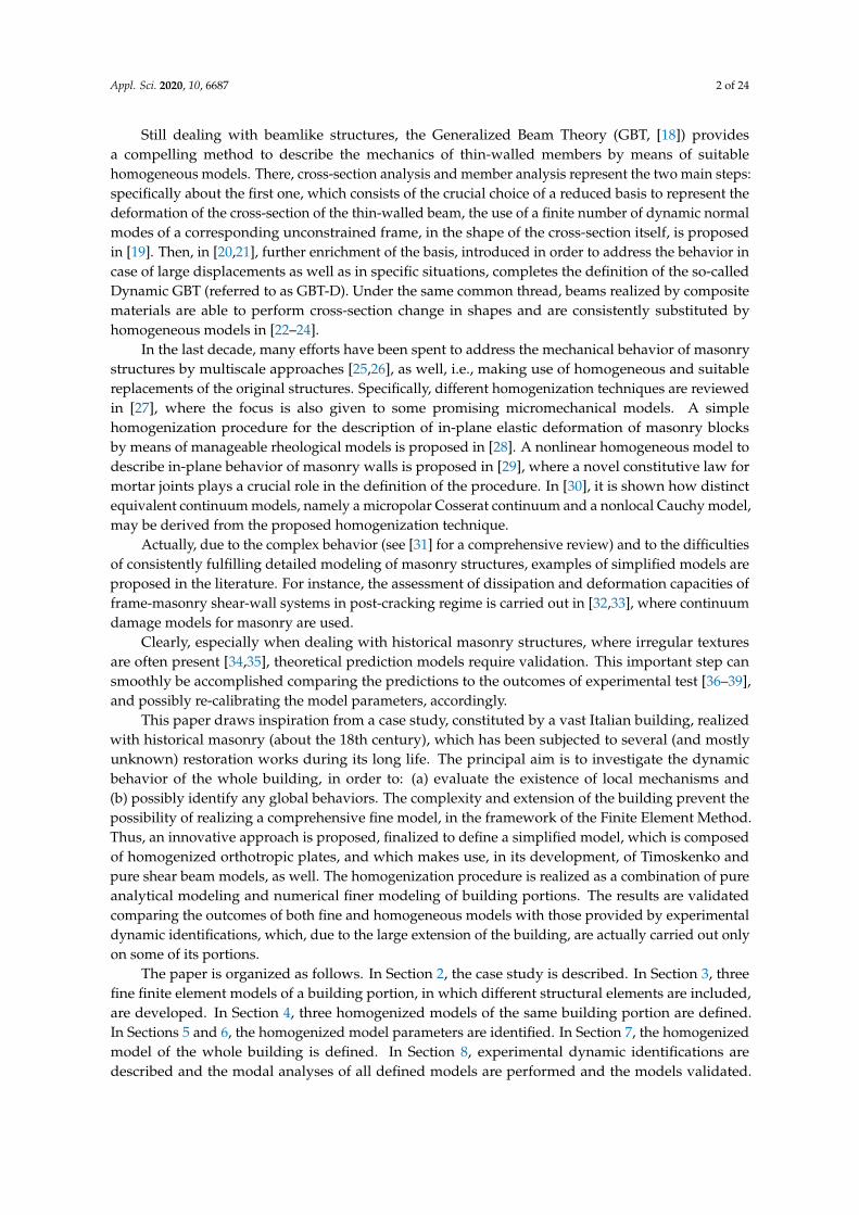
Still dealing with beamlike structures, the Generalized Beam Theory (GBT, [18]) providesa compelling method to describe the mechanics of thin-walled members by means of suitablehomogeneous models. There, cross-section analysis and member analysis represent the two main steps:specifically about the first one, which consists of the crucial choice of a reduced basis to represent thedeformation of the cross-section of the thin-walled beam, the use of a finite number of dynamic normalmodes of a corresponding unconstrained frame, in the shape of the cross-section itself, is proposedin [19]. Then, in [20,21], further enrichment of the basis, introduced in order to address the behavior incase of large displacements as well as in specific situations, completes the definition of the so-calledDynamic GBT (referred to as GBT-D). Under the same common thread, beams realized by compositematerials are able to perform cross-section change in shapes and are consistently substituted byhomogeneous models in [22–24].
In the last decade, many efforts have been spent to address the mechanical behavior of masonrystructures by multiscale approaches [25,26], as well, i.e., making use of homogeneous and suitablereplacements of the original structures. Specifically, different homogenization techniques are reviewedin [27], where the focus is also given to some promising micromechanical models. A simplehomogenization procedure for the description of in-plane elastic deformation of masonry blocksby means of manageable rheological models is proposed in [28]. A nonlinear homogeneous model todescribe in-plane behavior of masonry walls is proposed in [29], where a novel constitutive law formortar joints plays a crucial role in the definition of the procedure. In [30], it is shown how distinctequivalent continuum models, namely a micropolar Cosserat continuum and a nonlocal Cauchy model,may be derived from the proposed homogenization technique.
Actually, due to the complex behavior (see [31] for a comprehensive review) and to the difficultiesof consistently fulfilling detailed modeling of masonry structures, examples of simplified models areproposed in the literature. For instance, the assessment of dissipation and deformation capacities offrame-masonry shear-wall systems in post-cracking regime is carried out in [32,33], where continuumdamage models for masonry are used.
Clearly, especially when dealing with historical masonry structures, where irregular texturesare often present [34,35], theoretical prediction models require validation. This important step cansmoothly be accomplished comparing the predictions to the outcomes of experimental test [36–39],and possibly re-calibrating the model parameters, accordingly.
This paper draws inspiration from a case study, constituted by a vast Italian building, realizedwith historical masonry (about the 18th century), which has been subjected to several (and mostlyunknown) restoration works during its long life. The principal aim is to investigate the dynamicbehavior of the whole building, in order to: (a) evaluate the existence of local mechanisms and(b) possibly identify any global behaviors. The complexity and extension of the building prevent thepossibility of realizing a comprehensive fine model, in the framework of the Finite Element Method.Thus, an innovative approach is proposed, finalized to define a simplified model, which is composedof homogenized orthotropic plates, and which makes use, in its development, of Timoskenko andpure shear beam models, as well. The homogenization procedure is realized as a combination of pureanalytical modeling and numerical finer modeling of building portions. The results are validatedcomparing the outcomes of both fine and homogeneous models with those provided by experimentaldynamic identifications, which, due to the large extension of the building, are actually carried out onlyon some of its portions.
The paper is organized as follows. In Section 2, the case study is described. In Section 3, threefine finite element models of a building portion, in which different structural elements are included,are developed. In Section 4, three homogenized models of the same building portion are defined.In Sections 5 and 6, the homogenized model parameters are identified. In Section 7, the homogenizedmodel of the whole building is defined. In Section 8, experimental dynamic identifications aredescribed and the modal analyses of all defined models are performed and the models validated.

Appl. Sci. 2020, 10, 6687 3 of 24
Finally, in Section 9, the main findings of the work are summarized. Two appendices are presented atthe end of this paper.
2. The Case Study
The case study is an important ancient masonry building in Italy (headquarters of the ItalianMinistry of Economy and Finance—MEF, in Rome (Italy)). The building is located in a large rectangulararea, with sides 300 m and 120 m. The structure is a closed block with three internal courtyards,one main central and the other two lateral, arranged symmetrically with respect to the central transverseaxis of the building. The covered surface is about 19,000 m2, while the area on which the buildingstands is equal to 36,000 m2. The building is constituted by six levels, including a basement, a raisedground floor, four floors above, the latter of which is partly covered by a practicable slab. The averageheight is approximately 33 m overall.
Basically, the building can be thought as consisting of four transverse and six longitudinal armswith a width between 18 and 22 m and a variable length between 70 and 85 m. At the corners of thebuilding, there are also four small towers with turrets placed at the top. Each arm consists of a package offour parallel, longitudinal walls, two external (street side and courtyard side) and two internal (delimitinga corridor), connected by the horizontal elements and by transverse localized and distributed walls.
Moreover, due to the extension of the building: (i) different types of masonry (mainly tuff blocksand solid bricks and mortar) are present; (ii) the slabs are of various nature (as beams and vaults,vaults and arches, beams and flooring block, cement); (iii) in some cases, the presence of horizontalsystems (made with steel plates or rods) for chaining the walls has been found.
Plan and sections of the described building are shown in Figure 1.
+ 9.50
+ 9.50
+ 9.50
+ 9.50
+ 9.50
B
C’
AA’
103.5 103.567
274
54118
32
32
D’
D
AC
B’
(a)
Se C-C'ct.
5.9
5.3
7.05
5.85
5.05
7.05
Cortile
Se A-A'ct. Se B-B'ct.
PS 1
PT
P 1
P 2
P 3
P 4
Non rilevato
PS 1
PT
P 1
P 2
P 3
P 4
Non rilevato
3.85
1.17
0.27
5.00 5.
37
1.92
0.27
1.54
4.76
4.30
0.80
0.45
0.50
4.80
4.68
3.50
0.95
3.85
1.12
0.93
3.50
4.68
4.80
0.80
0.50
0.43
4.76
4.30
1.70
5.36
5.13
1.90
Via
Cortile
Se 'ct. D-D
3.08
0.48 0.48
3.85
3.42
0.50 0.55
PS 1
PT
P 1
P 2
P 3
P 4
0.50 0.48
3.77
3.77
4.77
4.87
3.57
1.02
0.922.98
4.72
4.87
4.05
5.27 5.48
1.10
1.20
4.54
3.75
0.55 0.55
3.75 3.98
0.96
1.49
4.34
0.75 0.74
4.73
6.50
6.59
4.38
1.64
1.72
4.62
0.79
3.223.55
3.59
3.36
3.22 3.55
0.78
4.62
1.76
1.48
4.34
0.60
2.40
4.93
6.55
2.40
0.60
4.27
1.36
4.73
U.T.A.
Serbatoio
acqua
15.78 1.50
5.95
6.97
6.98
5.77
3.98
3.95
6.73
4.21
4.39
7.001.2021.80
0.93
21.47 1.44
1.30
1.30
21.45 1.54
1.70 21.22 1.70
1.78
0.00
-2.11
0.60
5.10
3.2 5.3
(b)
Figure 1. (a) plan of the first level: (red) middle line and highlighted (gray filled area) longitudinal arm;(b) sections. All the units are in meters.

Appl. Sci. 2020, 10, 6687 4 of 24
For reasons that will be clear below, particular attention is addressed on the longitudinal armhighlighted in Figure 1a. A more detailed plan of the this latter, together with the perspectives of thetwo external facades, is shown in Figure 2. Concerning this building portion:
• the longitudinal walls taper from the bottom upwards with thicknesses ranging from 1.5 to 0.5 m;• the interstory heights are between 4 and 7 m;• the slabs consist of cross vaults (with fixed geometry and an estimated thickness of about 10 cm) at
the first three levels, and of steel beams with I sections (normal NP profile 300× 125), distributedwith inter-axis of 1.3 m, at the last two levels;
• couples of transverse walls, both localized (thickness about 70 cm) and of uniformly distributed(thickness about 15 cm) with an inter-axis of 3.9 m, stiffens the structure;
• the masonry is assumed everywhere of solid bricks and mortar;• the presence of horizontal systems for chaining the walls is assumed at the first three levels.
5.3
3.2
3.9
82
5.3
(a)
(b)
Figure 2. Long longitudinal arm details: (a) plan of the first floor; (b) perspectives of the twoexternal facades. All the units are in meters.
3. Fine Model of a Building Portion
First, a fine finite element model of a building portion is developed to study some structuralmechanisms and, then, to calibrate some parameters of the homogenized model. The studied portionconsists of the long longitudinal arm described in the case study, believed to be the most vulnerableseismically portion. Moreover, the long longitudinal arms are very similar to each other and themodest local differences can be considered such as not to significantly change the dynamic behavior.All the FEM models are implemented in the commercial software SAP 2000 [40].
The structural elements composing the studied arm are modeled as follows:
• The longitudinal and transverse walls and the vaults are modeled by homogeneous isotropicshell elements, having both a membrane and flexural behavior. Any element is a Cauchycontinuum body in plane stress, defined in a 2D space, and obeys a hyperelastic isotropic linearlaw according to the Young modulus Em = 2.2× 10⁶ kN/m2 and the Poisson factor νm = 0.15 ofthe block masonry.
• The slab beams are modeled by one-dimensional Timoshenko beam elements, axially, bending andshearing deformable. They obey to a hyperelastic isotropic linear law according the Youngmodulus Es = 2× 10⁸ kN/m2 and the Poisson factor νs = 0.3 of the steel.

Appl. Sci. 2020, 10, 6687 5 of 24
An equivalent averaged mass density ρ f = 3000 kg/m3 (1.6 times that of the masonry) is assignedto the only longitudinal shell elements; all the other elements are mass-free. The equivalent mass isobtained by allocating the total mass (deriving by the own weight of the vertical elements, accordingthe masonry mass density 1900 kg/m3, and the slab-bearing load equal to 11–15 kN/m2) to the onlylongitudinal walls.
The geometric and mechanical characteristics of the vertical and horizontal elements have beenassigned on the basis of information obtained from knowledge campaigns. Details about the geometrycan be found in Section 2. The soil–structure interaction was not taken into account, so that externalfixed constraints were applied to all the base nodes. The interaction with the other building arms ismodeled by hinge constraints applied to the nodes of the vertical sides of each facade.
In order to investigate the influence of the localized and distributed transverse walls, three finiteelement models are defined:
• the Longitudinal Wall (LW) fine model, composed only by a package of four parallel longitudinalwalls and horizontal slabs;
• the Longitudinal and Transverse Wall (LTW) fine model, composed by a package of four parallellongitudinal walls, horizontal slabs, and transverse distributed walls;
• the Stiffened Longitudinal and Transverse Wall (SLTW) fine model, composed by package of fourparallel longitudinal walls, horizontal slabs; and distributed and localized transverse walls.
In Figure 3a, a perspective view of the SLTW finite element model, made up of 39,353 nodes and40,183 elements, is shown. Different colors are used to distinguish different thicknesses of the shellelements, modeling: The longitudinal walls, in green scale, according the wall tapering; the vaults inred; the localized and distributed transverse walls, respectively, in dark and light blue. The modelincludes all the levels, with the exception of the last one, considered only as mass. Figure 3b showssome details about slabs and transverse walls.
(a)
(b)
Figure 3. Fine finite element model: (a) overview; (b) details of slabs and transverse walls.
Appl. Sci. 2020, 10, 6687 6 of 24
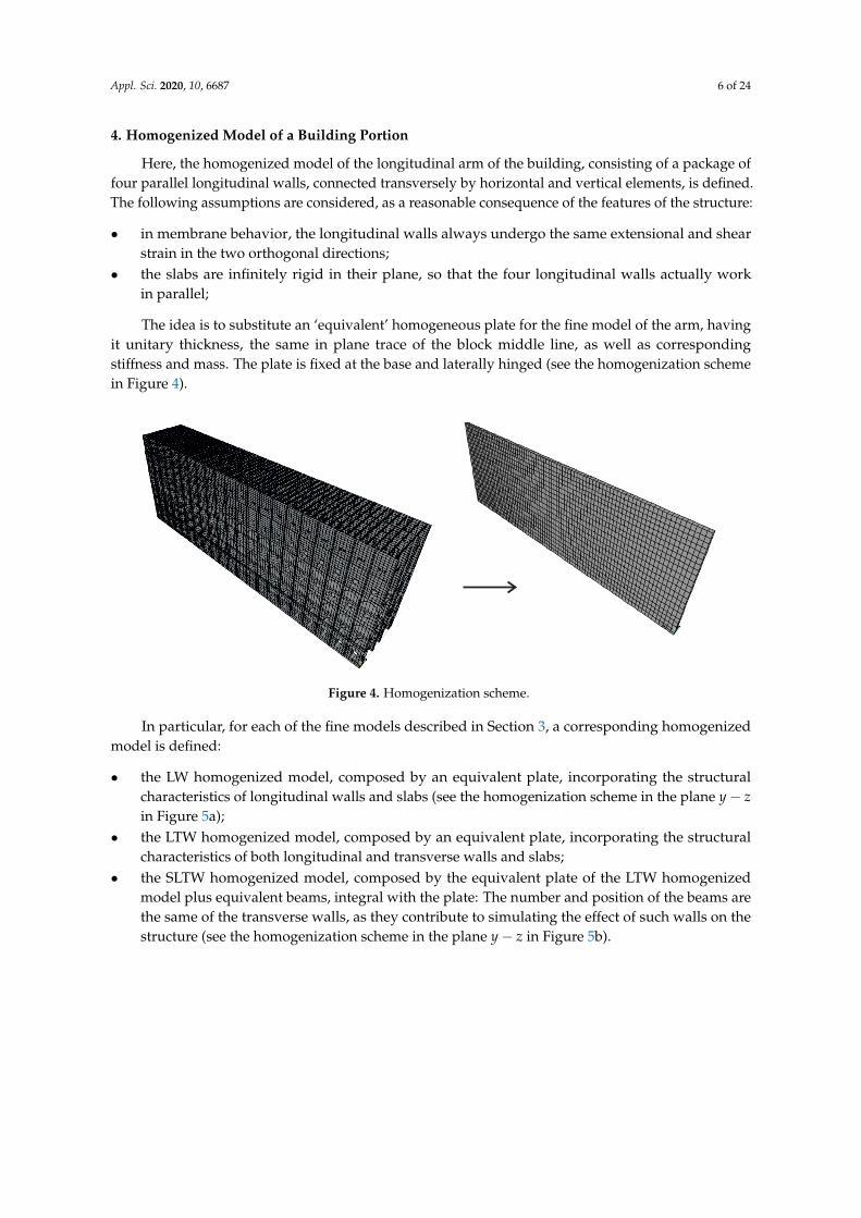
4. Homogenized Model of a Building Portion
Here, the homogenized model of the longitudinal arm of the building, consisting of a package offour parallel longitudinal walls, connected transversely by horizontal and vertical elements, is defined.The following assumptions are considered, as a reasonable consequence of the features of the structure:
• in membrane behavior, the longitudinal walls always undergo the same extensional and shearstrain in the two orthogonal directions;
• the slabs are infinitely rigid in their plane, so that the four longitudinal walls actually workin parallel;
The idea is to substitute an ‘equivalent’ homogeneous plate for the fine model of the arm, havingit unitary thickness, the same in plane trace of the block middle line, as well as correspondingstiffness and mass. The plate is fixed at the base and laterally hinged (see the homogenization schemein Figure 4).
Figure 4. Homogenization scheme.
In particular, for each of the fine models described in Section 3, a corresponding homogenizedmodel is defined:
• the LW homogenized model, composed by an equivalent plate, incorporating the structuralcharacteristics of longitudinal walls and slabs (see the homogenization scheme in the plane y− zin Figure 5a);
• the LTW homogenized model, composed by an equivalent plate, incorporating the structuralcharacteristics of both longitudinal and transverse walls and slabs;
• the SLTW homogenized model, composed by the equivalent plate of the LTW homogenizedmodel plus equivalent beams, integral with the plate: The number and position of the beams arethe same of the transverse walls, as they contribute to simulating the effect of such walls on thestructure (see the homogenization scheme in the plane y− z in Figure 5b).

Appl. Sci. 2020, 10, 6687 7 of 24
zz
yy
z
yy
(a) (b)
Figure 5. Homogenization scheme in the plane y− z of: (a) the LW model; (b) a couple of localizedtransverse walls.
The equivalent plates are orthotropic Mindlin–Reissner plates [41], having the following elasticconstitutive laws in the decoupled form:
Mx = Dxkx
My = Dyky
Mxy = Dxykxy
Tx = Sxγx
Ty = Syγy
Nx = Bxεx
Ny = Byεy
Nxy = Bxyγxy
(1)
where:
• Mx, My, Mxy are the bending and twist moments; Tx, Ty the shear forces; Nx, Ny, Nxy themembrane forces;
• kx = −w,xx, ky = −w,yy, kxy = −2w,xy are the bending and twist curvature, with w the orthogonaldisplacement of the plate; γx, γy are the out of plane sliding; εx, εy, γxy the membrane strains(unit extensions εx, εy and shear sliding γxy).
• Dx, Dy, Dxy are the bending and twist stiffness; Sx, Sy the out-of-plane shear stiffness; Bx, By, Bxy
the membrane stiffness.
Note that, contrary to standard constitutive equations constructed by homogenization, as showne.g., in [42], here the off-diagonal terms are neglected, by assuming the Poisson factor to be zero.This assumption: (i) is reasonable in the context of the approximations of the problem, in whichthe Poisson effect plays a certainly minor role; and (ii) remarkably simplifies the homogenizationprocedures, by allowing to identify separately the plate elastic constants relative to different directions.
The identification of the equivalent in-plane and out-of-plane elastic constants represents animportant goal of the work. In particular, since the geometry varies in height (due to wall taperingand different kinds of slabs), each homogenized model is actually composed by five equivalent plates,having the corresponding interstory height, numbered from bottom to top as in Figure 6. Each of thefive plates has to be identified. The problem is stated as follows: the geometry of the assembly beingknown as well as the elastic properties of the elements, determining the elastic stiffness coefficients

Appl. Sci. 2020, 10, 6687 8 of 24
Dx, Dy, Dxy, Sx, Sy, Bx, By, Bxy of each equivalent plate. This is made, in part, from a pure analyticalmodeling and, in part, through numerical finer modeling.
x
y
1
2
3
4
5
Figure 6. Scheme of the equivalent plates of the homogenized model.
Concerning the equivalent mass of the homogeneous plates, an average mass densityρh = 8700 kg/m3 is determined by dividing the total load of the longitudinal arm for the plate volume.All the other elements are considered mass-free.
5. LW Homogenized Model Identification
Preliminary analyses, carried out on the LW fine model, showed that the out-of-plane behavioris substantially equivalent to that of a pure shear plate. Therefore, the equivalent bending and twiststiffness coefficients are assumed Dx = Dy = Dxy = ∞, and the identification procedure is limited todetermine the six elastic membrane and shear stiffness coefficients (Sx, Sy, Bx, By, Bxy), for each of thefive equivalent plates. Different approaches are used:
• the in-plane behavior is characterized by energy equivalences on the basis of exclusivelyanalytical models;
• the out-of-plane behavior is characterized by displacement equivalences on the basis of finenumerical models: This more involved approach is due to the physics of the problem where mainlyduring out-of-plane displacements, interaction between vertical and horizontal structures occurs.
5.1. In-Plane (Membrane) Behavior
Assuming each wall of the fine model to behave as a homogeneous and isotropic Cauchycontinuum, of elastic Young modulus and Poisson factor Em, νm, respectively, the membrane elasticconstants Bx,By,Bxy are determined for the equivalent plates at the different stories as follows.
On any of the stories, the longitudinal walls are characterized by almost identical windows,periodically repeated along the length. Therefore, it is easy to identify Representative Volume Elements(RVE), whose assembly reproduces the walls: A rectangular cell of dimensions ax × ay, where ax is thecenter distance of the windows, ay the interstory height, x and y the horizontal and vertical directions,respectively, is used as RVE; see details in Figure 7a. In each of the four longitudinal wall, the rectanglecell circumscribes a I region, centered on the cell and derived by the intersection between a male walland part of two horizontal bands. The four I regions are distinguished by the different wall thicknesshi (with i = 1, ..., 4) and by different void dimensions that are 2bx × 2by1 in the two external facadesand 2bx × 2by2 in the two internal facades; see Table 1. Note that, whereas the dimensions along x areconstant, those along y vary.

Appl. Sci. 2020, 10, 6687 9 of 24
x
y
ax
ay
bx bx
by
(a) (b)
Figure 7. (a) cell geometry; (b) modified I domain under extensional strains: subtraction of the regionsat almost zero-strain.
Table 1. Cell geometry; numerical values in meters.
Homogeneous Plate ax ay bx by1 by2 h1 h2 h3 h4
1 3.8 5.90 0.76 2.72 2.72 1.49 0.62 0.62 1.662 3.8 7.05 0.76 2.73 5.61 1.3 0.57 0.57 1.43 3.8 7.05 0.76 2.78 2.40 1.26 0.57 0.57 1.14 3.8 5.85 0.76 2.53 3.75 0.94 0.52 0.52 0.985 3.8 5.05 0.76 1.28 3.77 0.52 0.49 0.49 0.52
The identification of the membrane elastic stiffness coefficients of each plate is made by equatingthe strain energy of the four I cells and of the equivalent rectangular cell, of dimensions ax × ay andunitary out-of-plane thickness, once the same in-plane strain is applied, assumed constant on thecell domain. Longitudinal strain along x- and y-directions are applied to determine the extensionalelastic coefficients:
Bx = Em
4
∑i=1
hi
[1−
2bxbyi
axay−(ax − 2bx)
(ax − 2bx − 2byi
)2axay
]
By = Em
4
∑i=1
hi
(1−
2bxbyi
axay− 2b2
xaxay
),
(2)
and shear strain is applied to determine the membrane shear stiffness coefficient:
Bxy = Gm
4
∑i=1
hi
(1−
2bxibyi
axay
)(3)
where by3 = by2 and by4 = by1. It is worth noticing that these identified coefficients are proportional tothe full-void difference of the cell, namely:
1−2bxibyi
axay(4)
As a further comment to get Equation (2), the regions at almost zero-strain (according the realstrain distributions) are subtracted to the domain of the I region, as shown in Figure 7b.

Appl. Sci. 2020, 10, 6687 10 of 24
Validation of the identification procedure comes from good agreement in comparing the outcomesof finite element models, when both the fine and homogeneous structures are subjected to the samein-plane solicitations. The numerical results are reported in Table 2.
5.2. Out-of-Plane (Shear) Behavior
The identification of out-of-plane behavior implies a higher complexity due to the influence of thecollaborating slabs. Therefore, to this aim, the LW fine finite element model described in Section 3,under suitable load and constraint conditions, is used. Here, the geometry of the assembly beingknown as well as the elastic properties of the elements, the out-of-plane shear elastic constants (Sx,Sy)of each homogenized plate are determined as follows.
First, coefficient Sx is identified. To this aim, the LW fine model, released to the base(but still hinged at the sides) and subjected to a horizontal, uniformly distributed load of intensityp = 1000 N/m2 on the surface of the most external facade, is analyzed. The deformed configurationof the fine model is shown in Figure 8 in (a) the 3D space and (b) the x− z plane. It is observed that(a) the out-of-plane deformation is strongly influenced by the stiffness difference along y and (b) theslab beams rigidly move forward, as the cross-sections of a pure shear beam fixed at the ends.
(a) (b)
Figure 8. Sx identification. Deformed configuration of the fine model in the: (a) 3D space; (b) x− z plane.
Therefore, the idea is to consider five equivalent pure shear beams, i.e., one for each story, with theaxis-line along x, and calibrate the relevant stiffness coefficients GAi (for i = 1, ..., 5). The shear beamshave a length of L = 82 m, i.e., the arm length, are fixed at the ends and are subjected to a uniform loadpayi, with ayi the interstory height (Table 1); see the scheme in Figure 9a. The identification is made bya displacement equivalence between numerical and analytical models: The out-of-plane displacements
of the fine model, evaluated at x =L2
and at half height of each interstory, are equated to the mid-span
displacement of the equivalent shear beam, namely wi
(L2
)= pL2
8GAi, which come from the analytical
solving of the relevant differential boundary value problem:
GAiw′′i (x) = −p
wi(0) = 0 for i = 1, ..., 5
wi(L) = 0
(5)
The unknown stiffness coefficient GAi is thus obtained and, from them, the equivalent plate
coefficient comes as Sxi =GAiayi
; numerical values are in Table 2. In Figure 9b, a comparison between

Appl. Sci. 2020, 10, 6687 11 of 24
the equivalent beam (i = 5) and fine model deformed configurations in the x− z plane is shown, and avery good agreement is observed.
p ayi
w xi( )
x
L
G Ai
0 20 40 60 80
0.000
0.005
0.010
0.015
0.020
x
w
(a) (b)
Figure 9. (a) scheme of the shear beam equivalent to the i-plate; (b) comparison between analytical(pink line) and numerical (black line) deformations in the x− z plane for the plate 5; quantities in meters.
As a further step, the out-of-plane shear stiffness coefficient Sy is identified. To this aim, a centralvertical strip of width ax is extracted from the LW fine model. A distribution of horizontal forces,
equivalent to the triangular loadp
H5y with p = 2000 N/m and H5 = 31 m, which is the total height
of the wall, is applied to the external facade; the interaction with the adjacent strips is neglected.The out-of-plane displacement of the fine model is shown in Figure 10a, in the 3D space, and inFigure 10b, in the y− z plane. It is observed that the deformation is substantially similar to that of ashear-type frame with total height H5, deriving by a pure shear behavior of the interstory walls.
(a) (b)
Figure 10. Sy identification. Deformed configuration of the fine model in the: (a) 3D space; (b) y− z plane.
Therefore, for the aforementioned purpose, five equivalent pure shear beams, arranged in seriesand having axis-line along y and length ayi, are considered. The shear beams are fixed at the base and
subjected to the triangular loadp
H5y; see the scheme in Figure 11a. The identification of the relevant
shear stiffness coefficients GAi (i = 1, ..., 5) is carried out, as for the previous case, by a displacementequivalence between numerical and analytical models: The out-of-plane displacement of the fine

Appl. Sci. 2020, 10, 6687 12 of 24
model, evaluated at floor level y = Hi and at half width of the strip, is equated to the analyticalexpressions wi (Hi). The latter come from solving the following differential boundary value problem,composed by field equations, continuity conditions at y = Hi and the geometric and mechanicalconditions at the boundary:
GAiw′′i (y) = −p
H5y for i = 1, ..., 5
w1(0) = 0
wi(Hi) = wi+1(Hi)
GAiw′i(Hi) = GAi+1w′i+1(Hi)
}for i = 1, ..., 4
GA5w′5(H5) = 0
(6)
The unknown equivalent stiffness coefficients GAi are consistently obtained and, accordingly,
the plate stiffness coefficients are Syi =GAiax
; their numerical values are shown in Table 2. In Figure 11b
a comparison between the deformed configurations of analytical and numerical models in the y− zplane are shown, indicating a very good agreement.
pw5( )y
w4( )y
w3( )y
w2( )y
w1( )y
y
GA5
H5
H4
H3
H2
H1
GA4
GA3
GA2
GA1 0.000 0.005 0.010 0.015
0
5
10
15
20
25
30
w
y
(a) (b)
Figure 11. (a) scheme of the equivalent shear beam system with axis y; (b) comparison betweenanalytical (pink line) and numerical (black line) deformations in the y− z plane; quantities in meters.
5.3. Summary of the Identified Equivalent Parameters
In accordance with the homogenization procedures described above, the numerical values of theidentified stiffness coefficients (in N/m) for the LW homogenized model are collected in Table 2 foreach plate.
Table 2. Identified equivalent stiffness coefficients (in N/m) for the LW homogenized model.
Homogeneous Plate Dx = Dy = Dxy Sx Sy Bx By Bxy
1 ∞ 7.3× 10⁷ 3.3× 10⁷ 9.4× 10⁹ 7.4× 10⁹ 3.9× 10⁹
2 ∞ 6.1× 10⁷ 1.1× 10⁷ 8.5× 10⁹ 6.4× 10⁹ 3.4× 10⁹
3 ∞ 5.2× 10⁷ 6.5× 10⁶ 7.5× 10⁹ 6.2× 10⁹ 3.3× 10⁹
4 ∞ 4× 10⁷ 4.6× 10⁶ 6.3× 10⁹ 4.8× 10⁹ 2.6× 10⁹
5 ∞ 3.5× 10⁷ 2.3× 10⁶ 4.3× 10⁹ 3.3× 10⁹ 1.8× 10⁹

Appl. Sci. 2020, 10, 6687 13 of 24
6. LTW and SLTW Homogenized Models Identification
The LW homogenized model is enriched by adding first the distributed, and then both distributedand localized transverse walls, thus obtaining the LTW and SLTW homogenized models, respectively.In particular, in the LTW model, the transverse walls are distributed along the total length L of the arm,with an inter-axis ax, and affect in- and out-of-plane stiffness coefficients By and Sy of the equivalentplate. Furthermore, in the SLTW model, the localized transverse walls are modeled as equivalentbeams, integral with the LTW plate.
6.1. In-Plane (Membrane) Behavior
The transverse walls are assumed to influence the in-plane behavior of the equivalent platein the y-direction. They are modeled as beams with axis-line along y, having axial stiffness 2Em A,where A = 0.8 m2 is the cross-section area for the case of distributed walls, and A = 3.7 m2 forlocalized walls, respectively.
Therefore, in defining the LTW homogenized model, the contribution of the distributed beams onthe equivalent plate turns out to be an increase of the elastic coefficient By of the LW model, given in
Equation (2), of the value2Em A
ax= 9.26× 10⁸ N/m.
For the SLTW homogenized model, a further stiffening of the LTW model is due to the localizedbeams, which are integral with the plate and provide axial stiffness 2Em A = 1.55× 10¹⁰ (in which thecontribution of the partitions, incorporated in the plate, is subtracted).
6.2. Out-of-Plane (Shear) Behavior
In order to evaluate the out-of-plane behavior, each couple of transverse wall is modeled as aTimoshenko beam having an axis-line along y. Its bending and shear stiffness coefficients are piece-wiseuniform along each story, and are evaluated as 2Em Ii and 2Gm Ati (for i = 1, ..., 5), respectively,where principal inertia moment Ii and area Ati include the thickness of the two external and internallongitudinal walls to the cross-section of each transverse wall. However, since the beams are includedor attached to the pure shear plates of the homogenized model, they are forced to behave as pureshear beams as well. For this reason, a “reduced” equivalent shear stiffness GA∗i (for i = 1, ..., 5),also including the bending of the Timoshenko beams, is identified. This is made by a complementaryenergy equivalence between the Timoshenko beam (bending and shear stiffness coefficients 2Em Ii,2Gm Ati, respectively) and a pure shear beam (shear stiffness GA∗i ), of length ayi, fixed at the baseand subjected to a horizontal load at the top (details are given in Appendix A). The equivalent shearstiffness is found to be:
GA∗i =6Em IiGm Ati
3Em Ii + Gm Atia2yi
(7)
In defining the LTW homogenized model, the contribution of the distributed walls is finally
included in the equivalent plates as Syi =GA∗i
ax(reported in Table 3).
Then, the SLTW homogenized model is defined, by stiffening the LTW model by localized beams,integral with the plate and having shear stiffness GA∗i reported in Table 3 (the contribution of thepartitions, incorporated in the plate, is subtracted).

Appl. Sci. 2020, 10, 6687 14 of 24
Table 3. Shear stiffness coefficients of LTW model (in N/m) and equivalent beams in the SLTW model (in N).
Homogeneous Plate Sy GA∗
1 2.54× 10⁸ 3.63× 10⁹
2 1.93× 10⁸ 2.76× 10⁹
3 1.91× 10⁸ 2.73× 10⁹
4 2.12× 10⁸ 3.03× 10⁹
5 2.14× 10⁸ 3.07× 10⁹
Note that the shear stiffness of the LTW model is much higher than that of the LW model.
7. Global Homogenized Model
The case study consists of a very large building and this makes the finite element finemodeling very heavy and somehow impractical for the characterization of a possible global behavior.Therefore, the definition of a simplified homogenized model, with a reduced number of d.o.f., appearsas a convenient choice, when one is interested to address a large scale point of view. The purposeis indeed accomplished by substituting each arm of the building with five (one for each story)homogeneous plates. In this way, the building is thought of as a vertical tube, with a multi-cellularsection. In order to obtain a minimal and descriptive model of the dynamic behavior, despite theheterogeneity of the building, the same mechanical characteristics are assigned to the plates composingthe different arms. The latter are defined by the LW, LTW, or SLTW homogenized models of the longlongitudinal arm, as defined in the previous sections.
A perspective view of the finite element global homogenized model is shown in Figure 12.It consists of 4848 nodes and 4150 elements. The walls are modeled by in-series homogeneousorthotropic shell elements, of unitary out-of-plane thickness and having the length of the arm andinterstory height. Any element is a Cauchy continuum body in plane stress, defined in a 2D space.Different colors are used to distinguish the mechanical properties of each plate, defined by theLW or LTW homogenized models; localized massless beam elements are attached to the plates,when the SLTW homogenized model is considered. For details about the geometry, see Figure 1 Thesoil–structure interaction is not taken into account; therefore, external fixed constraints are applied tothe base nodes.
Figure 12. Overview of the finite element global homogenized model.

Appl. Sci. 2020, 10, 6687 15 of 24
8. Modal Analysis
First, experimental dynamic identification, carried out on building portions by R. Alaggio andE. Antonacci of the Structural Dynamic Laboratory of the University of L’Aquila (Technical Report notyet published at the time this paper is submitted, see Acknowledgments), is described. Then, modalanalyses of the fine models of a building portion are performed to study the influence of the transversewalls; these models are also validated on the base of the experimental results. Modal analyses ofthe homogenized models of the same building portion are also performed and the models validated.Finally, the dynamic behavior of the global homogenized model is studied to address possible localand global mechanisms.
8.1. Experimental Dynamic Identification
The experimentation was carried out to assess the dynamic behavior of the building, according tothe Output Only identification techniques, having the merit of reducing interference with the activitiescarried out routinely in the building. The processing of the acquired data is carried out according tomethods defined in the time (SSI, Stochastic SubSpace Identification) and frequencies (EFDD, EnhancedFrequency Domain Decomposition) domain, in order to produce a mutual validation of the modalparameters (frequencies, forms, and modal damping). The dynamic investigations are developedin two phases: (i) a first phase of design and execution of the dynamic tests; (ii) a second phase ofidentification of the modal parameters. Similar techniques were used also in [38,39].
Two test campaigns, involving a portion of the building, were carried out at two different times:
1. The test campaign 1 was carried out on the building portion highlighted in Figure 13a, at theonly second floor. The measuring instruments were arranged to measure the components of themotion at twelve points and, for each point, in two directions.
2. The test campaign 2 was carried out on the building portion highlighted in Figure 14b at the first,second, third, and fourth floor. Four measuring instruments were arranged at each floors in orderto measure the motion components in sixteen points.
Excerpts of the natural frequency and modal shapes of the first vibrating mode, obtained inboth the campaigns, are shown in Figures 13 and 14. It is observed that the first vibrating modemainly involves the out-of-plane behavior of the longitudinal arm, with the decidedly high naturalfrequency f = 1.54 Hz.
(a) (b)
Figure 13. (a) building portion affected by the dynamic tests of the campaign 1—second floor.First vibrating mode: natural frequency f = 1.54 and (b) modal shape in the x− z plane.
Appl. Sci. 2020, 10, 6687 16 of 24
(a) (b)
(c) (d)
Figure 14. (a) building portion affected by the dynamic tests of the campaign 2—first, second, third,fourth floor. First vibrating mode: natural frequency f = 1.54 and modal shapes in the (b) 3D space,(c) x− z plane, and (d) y− z plane. .
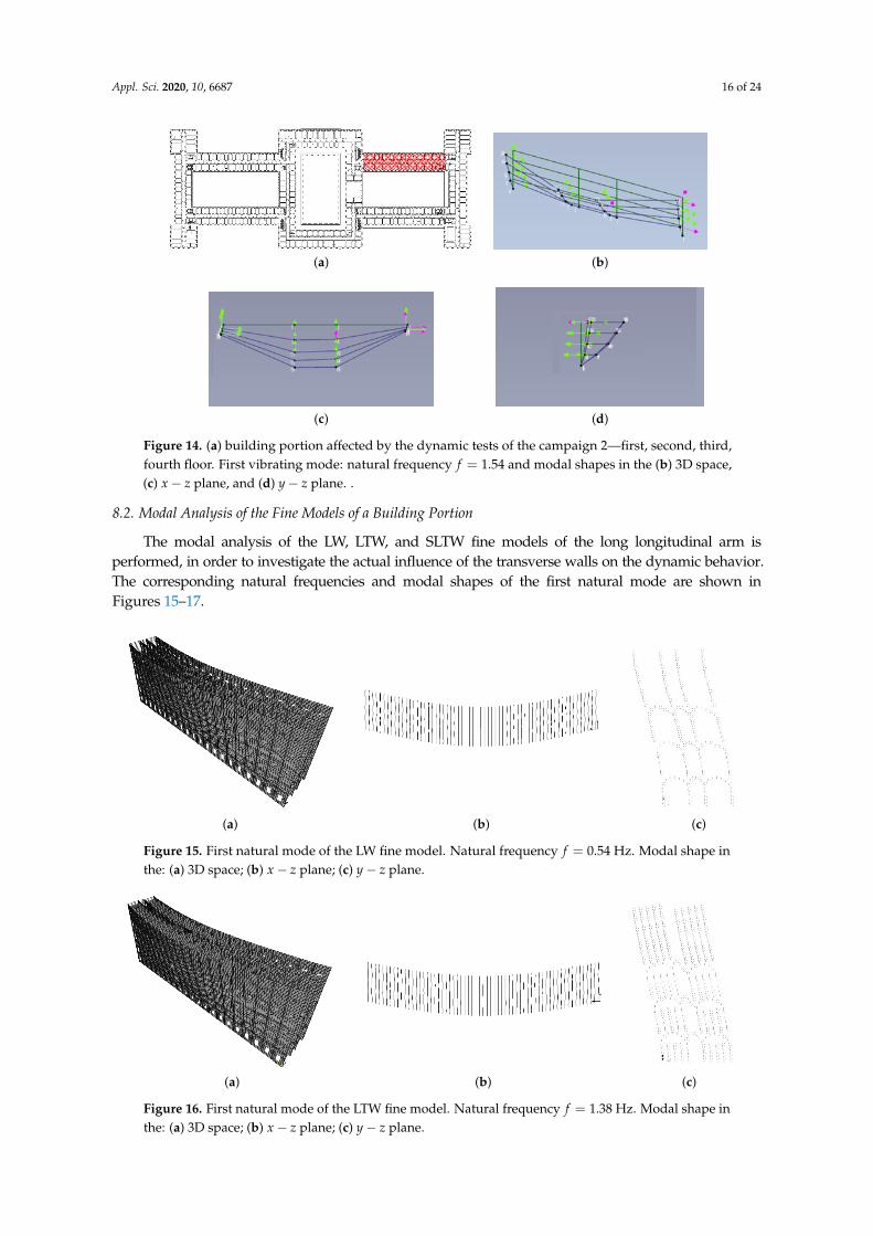
8.2. Modal Analysis of the Fine Models of a Building Portion
The modal analysis of the LW, LTW, and SLTW fine models of the long longitudinal arm isperformed, in order to investigate the actual influence of the transverse walls on the dynamic behavior.The corresponding natural frequencies and modal shapes of the first natural mode are shown inFigures 15–17.
(a) (b) (c)
Figure 15. First natural mode of the LW fine model. Natural frequency f = 0.54 Hz. Modal shape inthe: (a) 3D space; (b) x− z plane; (c) y− z plane.
(a) (b) (c)
Figure 16. First natural mode of the LTW fine model. Natural frequency f = 1.38 Hz. Modal shape inthe: (a) 3D space; (b) x− z plane; (c) y− z plane.

Appl. Sci. 2020, 10, 6687 17 of 24
(a) (b) (c)
Figure 17. First natural mode of the SLTW fine model. Natural frequency f = 1.42 Hz. Modal shape inthe: (a) 3D space; (b) x− z plane; (c) y− z plane.
First, it is seen that the first vibrating mode mainly involves the out-of-plane behavior of thestructure. The LW model is the less stiff, with a natural frequency f = 0.54 Hz. Moreover, pure shearmodal shapes are observed in the x− z and y− z planes. Concerning this aspect, some considerationsabout the significant influence of the slabs are reported in Appendix B. However, when the distributedtransverse walls are introduced, a significant increasing of the natural frequency reasonably occurs(the natural frequency of the LTW model is f = 1.38 Hz), together with a qualitative change of themodal shape in the y− z plane, in which also a bending behavior of the transverse walls is observed.Finally, the adding of the localized transverse walls further increases the frequency (the naturalfrequency of the SLTW model is f = 1.42 Hz) and, mainly, modifies the modal shape in the x− z plane,in which localized stiffening effects are evident.
By comparing the numerical results with the experimental ones of Section 8.1, it is evident howdecisive appears the contribution of the transverse walls. The SLTW fine model captures quite wellthe experimental results, with a percent error in frequency of about 7.8%. However, an evident erroris related to the hinge constraints at the lateral sides of the longitudinal walls of the fine model,which could be conveniently substituted by horizontal springs (appropriately calibrated, possibly infurther investigations).
8.3. Modal Analysis of the Homogenized Models of a Building Portion
The modal analyses of the LW, LTW, and SLTW homogenized models of the same longitudinalarm are performed, with the purpose of validating the (rough) homogenized models by means of thecorresponding fine ones, as well as evaluating how the natural frequency provides a “global” measureof the accuracy of the homogenization procedure. Natural frequencies and modal shapes of the firstnatural mode are shown in Figures 18–20.
(a) (b) (c)
Figure 18. First natural mode of the LW homogenized model. Natural frequency f = 0.46 Hz. Modalshape in the: (a) 3D space; (b) x− z plane; (c) y− z plane.

Appl. Sci. 2020, 10, 6687 18 of 24
(a) (b) (c)
Figure 19. First natural mode of the LTW homogenized model. Natural frequency f = 1.23 Hz.Modal shape in the: (a) 3D space; (b) x− z plane; (c) y− z plane.
(a) (b) (c)
Figure 20. First natural mode of the SLTW homogenized model. Natural frequency f = 1.44 Hz.Modal shape in the: (a) 3D space; (b) x− z plane; (c) y− z plane.
8.4. Modal Analysis of the Global Homogenized Model
Finally, the modal analysis of the global homogenized model is carried out. The aim isto investigate the occurrence of a global dynamic behavior rather than local mechanisms ofmacro-elements. It is worth noticing that such an analysis, if performed with a fine model of the wholestructure, is impractical.
First, the global LTW homogenized model is studied. It is found that the dynamic behavioris characterized mainly by out-of-plane movements of macro-elements, composed by the buildingarms. Frequency and modal shape of the most qualitatively significanty natural modes, namely 1,5,7,are shown in Figure 21. In particular, the natural modes 1–4 involve the long longitudinal armswith frequencies of about f = 1.2 Hz, the natural modes 5–6 involve the short longitudinal armswith frequencies of about f = 1.25 Hz and the natural modes 7–10 involve the transverse arms withfrequencies of about f = 1.3 Hz.

Appl. Sci. 2020, 10, 6687 19 of 24
Mode Frequency Modal shape
1 f = 1.2 Hz
5 f = 1.25 Hz
7 f = 1.3 Hz(a) (b)
Figure 21. Natural modes of the global LTW homogenized model. Modal shape in the (a) 3D space;(b) x− z plane.
Moreover, as a confirmation of the occurrence of local dynamic mechanisms, it is observedalso that the first mode is about the same as that of the homogenized model representing the onlylongitudinal arm (see Figure 16). This specific aspect is mainly due to the geometry of the building,and allows one to directly address the study to the single arms, eventually developing finer models.
When the localized transverse walls are added and the global SLTW homogenized model isstudied, the dynamic behavior continues to be characterized mainly by out-of-plane local movementsof macro-elements, consisting of the building arms. Frequency and modal shape of the natural modes 1,5 are shown in Figure 22. The natural modes 1–4 involve the transverse arms with frequencies ofabout f = 1.3 Hz and the natural modes 5–8 involve the long longitudinal arms with frequencies ofabout f = 1.33 Hz; the other modes are the higher modes of the long longitudinal arms and, therefore,are not reported.

Appl. Sci. 2020, 10, 6687 20 of 24
Mode Frequency Modal shape
1 f = 1.3 Hz
5 f = 1.33 Hz(a) (b)
Figure 22. Natural modes of the global SLTW homogenized model. Modal shape in the (a) 3D space;(b) x− z plane.
It is interesting to note that the addition of localized beams, as defined in the SLTW model,causes a reversal of the modes order. This is a consequence of the effect of the localized walls,which increase the out-of-plane modal stiffness of the arms in a different way, depending on the modenumber. Indeed, compared to the frequency of the modes 1, 5, 7 of the LTW model, where localizedtransverse walls are absent, for the SLTW, it is increased of 10.8%, 39% and 0%, respectively. As afurther observation, the natural frequencies of the global SLTW homogenized model are very close toeach other, so as to result in being very sensitive to the definition of the localized elements. This aspectcould induce, for some configurations, the occurrence of simultaneous modes, which might be worthyof investigation.
9. Conclusions
In order to have a clear insight into the dynamic behavior of a vast historical building,a homogeneous mechanical model has been addressed here. This specific approach has been motivatedby the structural characteristics of the building, constituting of a complex assembly of masonry walls,vaults, arches, slabs, which make in fact impractical the realization of a refined finite element model.The homogeneous model is made of linear orthotropic plates, which change their elastic properties atany story; furthermore, in the definition of the material response function, it has been taken advantageof the feasible individuation of a Representative Volume Element, from the periodic repetition of malewalls and windows.
Three possible versions have been formulated, referred to as LW, LTW, and SLTW, respectively,where the equivalent plate has been progressively enriched with the contributions of distributedand localized beams, so as to account for the effects of the transverse walls. Specifically, structuralmodels of Mindlin–Reissner plates, alternatively combined either with Timoshenko or pure shearbeams, have been used depending on the representation of in-plane or out-of-plane behavior.The corresponding constitutive parameters have been then calibrated with the use of fine FE models ofportions of the building.
It has been seen how the obtained homogeneous models are handy and, as a major result,well capture the first modal properties of the building, as compared to outcomes of experimental

Appl. Sci. 2020, 10, 6687 21 of 24
dynamic identification which are carried out for practical reasons only on a portion of the structure.Moreover, the homogeneous model allows one to analyze the global behavior of the building, providinga significant interpretation of the relationship intercurring between global and local mechanisms.Notably, it has been found that dynamics are mainly characterized by out-of-plane movements ofthe macro-elements composed of the building arms, thus addressing how the local mechanismsconcur in delineating the global behavior of the structure. This aspect is a consequence of the specificgeometry of the building, and justifies the possibility of directly addressing the study to the singlearms, eventually developing finer models.
With reference to the LTW model, it turns out that the natural modes 1–4 involve out-of-planemotions of the long longitudinal arms, with frequencies of about f = 1.2 Hz, while modes 5–6 involvethe short longitudinal arms, with frequencies of about f = 1.25 Hz, and modes 7–10 the transversearms with frequencies of about f = 1.3 Hz. Further improvement of the model, specifically referringto the SLTW configuration, causes a reversal of the modal order, possibly due to the closeness of thedifferent natural frequencies and the high sensitivity of the model.
Author Contributions: Conceptualization, S.D.N.; methodology, S.D.N.; investigation, S.D.N.; validation, S.D.N.;writing—original draft, S.D.N. and D.Z.; supervision, D.Z.; writing—review and editing, D.Z.. All authors haveread and agreed to the published version of the manuscript.
Funding: This research was partially supported by MEF (Italian Ministry of Economy and Finance) under theresearch program “Preparatory studies for the seismic improvement of the building Palazzo delle Finanze”.
Acknowledgments: The authors thank Rocco Alaggio and Elena Antonacci (University of L’Aquila) who carriedout the experimental tests and the dynamic identification procedures. Finally, the authors thank Angelo Luongo(University of L’Aquila)for his comments that greatly improved the quality of the manuscript.
Conflicts of Interest: The authors declare no conflict of interest.
Appendix A. Complementary Energy Equivalence
The elastic complementary energies of a Timoshenko beam, with bending and shear stiffnesscoefficients 2Em Ii and 2Gm Ati, and of a pure shear beam, with equivalent shear stiffness coefficientGA∗i , both having axis-line along y and length ayi, are respectively:
Vt =12
∫ ayi
0
(T2
2GAti+
M2
2EIi
)dy
Vs =12
∫ ayi
0
(T2
GA∗i
)dy
(A1)
where the bending moment and the shear force, when the beams are fixed at the base and subjected toa horizontal load F at the top, are:
T = F
M = Fayi − Fy(A2)
By the energy equivalence Vt = Vs, the explicit expression of the shear stiffness coefficient inEquation (7) is obtained.
Appendix B. Some Considerations about the Slab Influence on the Out-of-Plane Behavior
Preliminary numerical analyses, performed on the LW fine model, showed that the additionof collaborating slabs significantly changes the out-of-plane behavior, both in qualitative andquantitative terms.
Natural frequencies and modal shapes of the first vibrating mode of the LW fine model withoutslabs are shown in Figure A1. These have to be compared with Figure 15.

Appl. Sci. 2020, 10, 6687 22 of 24
(a) (b) (c)
Figure A1. First natural mode of the LW fine model without slabs. Natural frequency f = 0.24 Hz.Modal shape in the: (a) 3D space; (b) x− z plane; (c) y− z plane.
A significant decreasing of the natural frequency is observed, together with a qualitative change ofthe modal shape. In particular, the collaboration of the slabs (i) increases the frequency of 2.24 times and(ii) modifies the deformed configuration in the y− z plane, passing from a bending-type deformationto a shear-type frame deformation, with an actual span length H equal to the facade height (note thatthe stiffness ratio between the two analytical models is 4).
References
1. Noor, A. Continuum Modeling for Repetitive Lattice Structures. Appl. Mech. Rev. 1988, 41, 285–296.[CrossRef]
2. Boutin, C.; dell’Isola, F.; Giorgio, I.; Placidi, L. Linear pantographic sheets: Asymptotic micro-macro modelsidentification. Math. Mech. Complex Syst. 2017, 5, 127–162. [CrossRef]
3. Luongo, A.; Zulli, D. Mathematical Models of Beams and Cables; Iste-Wiley: London, UK, 20134. D’Annibale, F.; Ferretti, M.; Luongo, A. Shear-shear-torsional homogeneous beam models for nonlinear
periodic beam-like structures. Eng. Struct. 2019, 184, 115–133. [CrossRef]5. Ferretti, M.; D’Annibale, F.; Luongo, A. Buckling of tower-buildings on elastic foundation under compressive
tip-forces and self-weight. Contin. Mech. Thermodyn. 2020. [CrossRef]6. Ferretti, M. Flexural torsional buckling of uniformly compressed beam-like structures. Contin. Mech. Thermodyn.
2018, 30, 977–993. [CrossRef]7. Ferretti, M.; D’Annibale, F.; Luongo, A. Modeling beam-like planar structures by a one-dimensional continuum:
An analytical-numerical method. J. Appl. Comput. Mech. 2020, doi:10.22055/jacm.2020.33100.2150. [CrossRef]8. Luongo, A.; D’Annibale, F.; Ferretti, M. Shear and flexural factors for homogenized beam models of planar
frames. Eng. Struct. 2020, Submitted,9. Luongo, A.; Zulli, D. Free and forced linear dynamics of a homogeneous model for beam-like structures.
Meccanica 2020, 55, 907–925. [CrossRef]10. Zulli, D.; Luongo, A. Nonlinear dynamics and stability of a homogeneous model of tall buildings under
resonant action. J. Appl. Comput. Mech. 2020, Submitted.11. Piccardo, G.; Tubino, F.; Luongo, A. Equivalent Timoshenko linear beam model for the static and dynamic
analysis of tower buildings. Appl. Math. Model. 2019, 71, 77–95. [CrossRef]12. Piccardo, G.; Tubino, F.; Luongo, A. A shear–shear torsional beam model for nonlinear aeroelastic analysis
of tower buildings. Z. Angew. Math. Phys. 2015, 66, 1895–1913. [CrossRef]13. Piccardo, G.; Tubino, F.; Luongo, A. Equivalent nonlinear beam model for the 3D analysis of shear-type
buildings: Application to aeroelastic instability. Int. J. Non-Linear Mech. 2016, 80, 52 – 65. [CrossRef]14. Luongo, A.; Zulli, D. Parametric, external and self-excitation of a tower under turbulent wind flow.
J. Sound Vib. 2011, 330, 3057–3069. [CrossRef]15. Di Nino, S.; Luongo, A. Nonlinear aeroelastic behavior of a base-isolated beam under steady wind flow.
Int. J. Non-Linear Mech. 2020, 119, 103340. [CrossRef]

Appl. Sci. 2020, 10, 6687 23 of 24
16. Zulli, D.; Luongo, A. Bifurcation and stability of a two-tower system under wind-induced parametric,external and self-excitation. J. Sound Vib. 2012, 331, 365–383. [CrossRef]
17. Zulli, D.; Di Egidio, A. Galloping of internally resonant towers subjected to turbulent wind.Contin. Mech. Thermodyn. 2015, 27, 835–849. [CrossRef]
18. Silvestre, N.; Camotim, D. Nonlinear Generalized Beam Theory for cold-formed steel members. Int. J. Struct.Stab. Dyn. 2003, 3, 461–490. doi:10.1142/S0219455403001002. [CrossRef]
19. Ranzi, G.; Luongo, A. A new approach for thin-walled member analysis in the framework of GBT.Thin-Walled Struct. 2011, 49, 1404–1414. [CrossRef]
20. Piccardo, G.; Ranzi, G.; Luongo, A. A complete dynamic approach to the GBT cross–section analysisincluding extension and shear modes. Math. Mech. Solids 2014, 19, 900–924. [CrossRef]
21. Ferrarotti, A.; Piccardo, G.; Luongo, A. A novel straightforward dynamic approach for the evaluation ofextensional modes within GBT ’cross-section analysis’. Thin-Walled Struct. 2017, 114, 52–69. [CrossRef]
22. Luongo, A.; Zulli, D. A nonlinear one-dimensional model of cross-deformable tubular beam. Int. J.Non-Linear Mech. 2014, 66, 33–42.
23. Luongo, A.; Zulli, D.; Scognamiglio, I. The Brazier effect for elastic pipe beams with foam cores. Thin-Walled Struct.2018, 124, 72–80.
24. Zulli, D. A one-dimensional beam-like model for double-layered pipes. Int. J. Non-Linear Mech. 2019,109, 50–62.
25. Addessi, D.; Sacco, E. Homogenization of heterogeneous masonry beams. Meccanica 2018, 53, 1699–1717,doi:10.1007/s11012-017-0758-2. [CrossRef]
26. Greco, F.; Leonetti, L.; Luciano, R.; Trovalusci, P. Multiscale failure analysis of periodic masonrystructures with traditional and fiber-reinforced mortar joints. Compos. Part B Eng. 2017, 118, 75–95,doi:10.1016/j.compositesb.2017.03.004. [CrossRef]
27. Lourenço, P.; Milani, G.; Tralli, A.; Zucchini, A. Analysis of masonry structures: Review of and recent trendsin homogenization techniques. Can. J. Civ. Eng. 2007, 34, 1443–1457, doi:10.1139/L07-097. [CrossRef]
28. Di Nino, S.; Luongo, A. A simple homogenized orthotropic model for in-plane analysis of regular masonrywalls. Int. J. Solids Struct. 2019, 167, 156–169.
29. Sacco, E. A nonlinear homogenization procedure for periodic masonry. Eur. J. Mech. A/Solids 2009,28, 209–222.
30. Addessi, D.; Marfia, S.; Sacco, E.; Toti, J. Modeling approaches for masonry structures. Open Civ. Eng. J.2014, 8, 288–300, doi:10.2174/1874149501408010288. [CrossRef]
31. D’Altri, A.; Sarhosis, V.; Milani, G.; Rots, J.; Cattari, S.; Lagomarsino, S.; Sacco, E.; Tralli, A.; Castellazzi, G.;de Miranda, S. Modeling Strategies for the Computational Analysis of Unreinforced Masonry Structures:Review and Classification. Arch. Comput. Methods Eng. 2019, doi:10.1007/s11831-019-09351-x. [CrossRef]
32. Pelà, L.; Cervera, M.; Roca, P. Continuum damage model for orthotropic materials: Application to masonry.Comput. Methods Appl. Mech. Eng. 2011, 200, 917–930. [CrossRef]
33. Di Nino, S.; DAnnibale, F.; Luongo, A. A simple model for damage analysis of a frame-masonry shear-wallsystem. Int. J. Solids Struct. 2017, 129, 119–134. [CrossRef]
34. Angiolilli, M.; Gregori, A. Triplet test on rubble stone masonry: Numerical assessment of the shearmechanical parameters. Buildings 2020, 10, 49. [CrossRef]
35. Gregori, A.; Angiolilli, M. Simulating shear-compression mechanical behavior of historical masonry panels:Sensitivity of 3D numerical models to input parameters. In Proceedings of the XVII ANIDIS—Italian SeismicEngineering Conference, Pistoia, Italia, 17–21 September 2017; pp. 111–121.
36. Aloisio, A.; Alaggio, R.; Fragiacomo, M. Dynamic identification of a masonry façade from seismic responsedata based on an elementary Ordinary Least Squares approach. Eng. Struct. 2019, 197, 109415. [CrossRef]
37. Aloisio, A.; Di Battista, L.; Alaggio, R.; Fragiacomo, M. Analysis of the forced dynamics of a masonry facadeby means of input-output techniques and a linear regression model. In Proceedings of the 7th InternationalConference on Computational Methods in Structural Dynamics and Earthquake Engineering, Crete, Greece,24–26 June 2019.
38. Aloisio, A.; Alaggio, R.; Fragiacomo, M. Dynamic identification and model updating of full-scale concretebox girders based on the experimental torsional response. Constr. Build. Mater. 2020, 264, 120146. [CrossRef]

Appl. Sci. 2020, 10, 6687 24 of 24
39. Aloisio, A.; Di Battista, L.; Alaggio, R.; Fragiacomo, M. Sensitivity analysis of subspace-based damageindicators under changes in ambient excitation covariance, severity and location of damage. Eng. Struct.2020, 208, 110235. [CrossRef]
40. Computers and Structures, I. CSI Analysis Reference Manual: SAP 2000; Compurers and Structures, Inc.:Berkeley, CA, USA, 2011.
41. Timoshenko, S.; Woinowsky-Krieger, S. Theory of Plates and Shells; McGraw-Hill: New York, NY, USA, 1959.42. Lewinski, T.; Telega, J.J. Plates, Laminates and Shells: Asymptotic Analysis And Homogenization; World Scientific:
Singapore, 2000.
c© 2020 by the authors. Licensee MDPI, Basel, Switzerland. This article is an open accessarticle distributed under the terms and conditions of the Creative Commons Attribution(CC BY) license (http://creativecommons.org/licenses/by/4.0/).