Home Safety and Automation System
140
Home Safety and Automation System Senior Design II – EEL 4915 Summer 2019 – Fall 2019 College of Engineering and Computer Science & College of Optics and Photonics Group 14 Avery Stevenson – Photonic Science and Engineering Felix Henriquez – Computer Engineering Guilherme Costa – Computer Engineering Matthew Allen – Computer Engineering
Transcript of Home Safety and Automation System

Home Safety and Automation System
Senior Design II – EEL 4915
Summer 2019 – Fall 2019
College of Engineering and Computer Science
&
College of Optics and Photonics
Group 14
Avery Stevenson – Photonic Science and Engineering
Felix Henriquez – Computer Engineering
Guilherme Costa – Computer Engineering
Matthew Allen – Computer Engineering

This Page Is Intentionally Left Blank

I
Table of Contents
1. Executive Summary .................................................................................................................... 1
2. Project Description ..................................................................................................................... 2
2.1. Project Motivation ................................................................................................................ 2
2.2. Goals & Objectives .............................................................................................................. 2
2.3. Requirements Specifications ................................................................................................ 2
2.4. House of Quality ................................................................................................................ 12
3. Research .................................................................................................................................... 13
3.1. Existing Similar Products and Projects .............................................................................. 13
3.1.1. SimpliSafe ................................................................................................................... 13
3.1.2. Digital Assistants ......................................................................................................... 13
3.1.3. Raspberry Pi Projects................................................................................................... 14
3.2. Relevant Technologies ....................................................................................................... 14
3.2.1. AC Thermostat ............................................................................................................ 14
3.2.2. Household Lighting ..................................................................................................... 17
3.2.3. Smart Outlet ................................................................................................................. 20
3.2.4. Wireless Technologies ................................................................................................. 22
3.2.5. Web Server Technologies ............................................................................................ 24
3.2.6. Cloud Computing Services .......................................................................................... 24
3.2.7. Databases ..................................................................................................................... 26
3.2.8. Web Technologies ....................................................................................................... 28
3.2.9. Front End Technologies ............................................................................................... 29
3.2.10. Front-End Frameworks .............................................................................................. 30
3.2.11. Infrared Sensing Technologies .................................................................................. 32
3.2.12. Blackbody Radiation ................................................................................................. 37
3.2.13. Raspberry Pi 3 Model B+ .......................................................................................... 39
3.2.14. Raspbian .................................................................................................................... 40
3.2.15. Project Management Tools ........................................................................................ 40
4. Related Standards and Design Constraints ............................................................................... 41
4.1. Related Standards ............................................................................................................... 41
4.1.1. IEEE 802.11 Wi-Fi ...................................................................................................... 41
II
4.1.2. Universal Serial Bus .................................................................................................... 41
4.1.3. HTTP ........................................................................................................................... 41
4.1.4. Hypertext Markup Language ....................................................................................... 42
4.1.5. Cascading Style Sheet ................................................................................................. 42
4.1.6. Coding Standards ......................................................................................................... 42
4.1.7. ZigBee ......................................................................................................................... 43
4.1.8. JSON ............................................................................................................................ 43
4.2. Design Constraints ............................................................................................................. 44
4.2.1. Economic and Time Constraints.................................................................................. 44
4.2.2. Environmental and Social Constraints ........................................................................ 44
4.2.3. Health and Safety Constraints ..................................................................................... 45
4.2.4. Manufacturability Constraints ..................................................................................... 45
4.2.5. Political Constraints ..................................................................................................... 46
4.2.6. Ethical Constraints ....................................................................................................... 46
4.2.7. Software Prototyping Constraints ................................................................................ 46
4.2.8. Testing Constraints ...................................................................................................... 47
5. Project Hardware and Software Design Details ....................................................................... 48
5.1. Hardware Design Details ................................................................................................... 48
5.1.1. AC Thermostat Design ................................................................................................ 48
5.1.2. SMART Outlet Design ................................................................................................ 53
5.1.3. Light Switch Design .................................................................................................... 57
5.1.4. Fire Detector Housing ................................................................................................. 61
5.2. Hardware Design Lessons Learned .................................................................................... 65
5.3. Software Design Details ..................................................................................................... 65
5.3.1. Microcontroller Components Software ....................................................................... 65
5.3.2. Considerations for Network Connection Between Hub and LAN .............................. 70
5.3.3. Networking Overview ................................................................................................. 72
5.3.4. Device Discovery ........................................................................................................ 73
5.3.5. Client-Server Communication ..................................................................................... 77
5.3.6. Software Block Diagram ............................................................................................. 84
5.3.7. Auxiliary Services ....................................................................................................... 85
5.3.8. System Security ........................................................................................................... 85

III
5.3.9. Class Diagrams ............................................................................................................ 85
5.3.10. User Interface Overview ............................................................................................ 86
5.3.11. Database Schema Overview ...................................................................................... 93
5.4. Optical Design Details ....................................................................................................... 95
5.5. Final Optics Specifications ................................................................................................ 97
5.5.1. Fire Hazard Detection Unit.......................................................................................... 97
5.5.2. Motion Sensor.............................................................................................................. 97
6. Prototype Testing ...................................................................................................................... 97
6.1. Hardware Testing ............................................................................................................... 97
6.1.1. AC Thermostat Testing Plan ....................................................................................... 97
6.1.2. Light Switch Testing Plan ......................................................................................... 101
6.1.3. Smart Outlet Test Plan ............................................................................................... 103
6.2. Software Testing .............................................................................................................. 104
6.2.1. Integrated Development Environments ..................................................................... 106
6.2.2. Website Testing ......................................................................................................... 106
6.3. Optics and Sensor Testing ................................................................................................ 109
6.3.1. Secondary Sensor Testing ......................................................................................... 114
7. User Manual ............................................................................................................................ 119
7.1. Account Management ...................................................................................................... 119
7.1.1. User Registration ....................................................................................................... 119
7.1.2. Profile Management .................................................................................................. 119
7.1.3. Dependents ................................................................................................................ 119
7.2. Dashboard ........................................................................................................................ 120
7.2.1. Devices ...................................................................................................................... 120
7.2.2. Motion Sensor............................................................................................................ 122
7.2.3. Fire Hazard Detector ................................................................................................. 123
7.2.4. Tasks .......................................................................................................................... 124
8. Future Improvements .............................................................................................................. 124
8.1. Fire Detection Improvements ........................................................................................... 124
9. Administrative Content ........................................................................................................... 127
9.1. Milestone Discussion ....................................................................................................... 127
9.2. Division of Responsibilities ............................................................................................. 128

IV
9.3. Budget Discussion ............................................................................................................ 129
Appendices .................................................................................................................................. 130
References ............................................................................................................................... 130
Copyright Permissions ............................................................................................................ 131
List of Figures
Figure 1. House of Quality............................................................................................................ 12
Figure 2. Legend for House of Quality ......................................................................................... 13
Figure 3. Wiring of an AC Thermostat ......................................................................................... 15
Figure 4. Example of Material Design for Bootstrap Component ................................................ 32
Figure 5. Example of Materialize CSS Component...................................................................... 32
Figure 6. Example of Bootstrap Component ................................................................................ 32
Figure 7. Working Mechanisms of PIR sensor [1] ....................................................................... 33
Figure 8. Transmission Spectrum of N-BK7 ................................................................................ 35
Figure 9. Transmission spectrum of Zinc Selenide ...................................................................... 35
Figure 10. Transmission Spectrum of Calcium Fluoride .............................................................. 36
Figure 11. Transmission Spectrum of Sodium Chloride .............................................................. 36
Figure 12. Transmission Spectrum of Magnesium Fluoride ........................................................ 37
Figure 13. Blackbody Emission Spectrum of “Typical” Hydrocarbon Fire ................................. 38
Figure 14. Transmission Spectrum of the Sun .............................................................................. 39
Figure 15. Example of PEP 8 Guideline ....................................................................................... 42
Figure 16. Correct Guideline Example – Django ......................................................................... 43
Figure 17. Wrong Guideline Example – Django .......................................................................... 43
Figure 18. Example of JSON object structure with nested object ................................................ 44
Figure 19. Hot Work Permit for Testing ....................................................................................... 47
Figure 20. Smart Thermostat Schematic ....................................................................................... 51
Figure 21. Smart Thermostat PCB Layout Mockup ..................................................................... 52
Figure 22. Smart Outlet Schematic ............................................................................................... 54
Figure 23. Smart Outlet PCB Layout Mockup ............................................................................. 56
Figure 24. Smart Light Switch Schematic .................................................................................... 58
Figure 25. Smart Switch PCB Mock Layout ................................................................................ 60
Figure 26. Sensor Housing with Lens Holder and Baseplate ....................................................... 61
Figure 27. Sensor Board Schematic .............................................................................................. 63
Figure 28. Sensor Board PCB Layout........................................................................................... 64
Figure 29. Function Diagram ........................................................................................................ 66
Figure 30. Software Process ......................................................................................................... 67
Figure 31. System Class Diagram ................................................................................................. 68
Figure 32. System Diagram .......................................................................................................... 68
Figure 33. Thermostat System Flowchart ..................................................................................... 69
Figure 34. Diagram of four-part WPA2 Handshake ..................................................................... 70

V
Figure 35. Example of a typical router WPS authentication button ............................................. 72
Figure 36. Network Diagram ........................................................................................................ 72
Figure 37. Ping Scan outline, with arrows representing ICMP ECHO requests .......................... 74
Figure 38. Example of DNS-SD based discovery of a network service ....................................... 75
Figure 39. Example of UDP-Broadcast ........................................................................................ 76
Figure 40. Possible outline of means by which user can associate a hub with their account. ...... 79
Figure 41. Example of POST Transaction .................................................................................... 82
Figure 42. Tentative Block Diagram ............................................................................................ 84
Figure 43. Tentative Block Diagram ............................................................................................ 84
Figure 44. User UML Diagram ..................................................................................................... 85
Figure 45. User and Dashboard Management............................................................................... 86
Figure 46. Login Layout Utilizing Materialize CSS ..................................................................... 87
Figure 47. Login Layout with Material Design for Bootstrap ...................................................... 87
Figure 48. Login Form .................................................................................................................. 88
Figure 49. Final Login Screen ...................................................................................................... 88
Figure 50. Registration Form ........................................................................................................ 89
Figure 51. Dashboard Overview Example .................................................................................... 90
Figure 52. Profile Information ...................................................................................................... 90
Figure 53. Profile Editing ............................................................................................................. 91
Figure 54. Example of Outlet Control .......................................................................................... 91
Figure 55. Registration and Login Flowchart ............................................................................... 92
Figure 56. Password Reset Flowchart ........................................................................................... 93
Figure 57. Example of User Information in Database .................................................................. 94
Figure 58. Example of User Information Stored with MongoDB ................................................ 94
Figure 59. Tentative Database Schema ......................................................................................... 95
Figure 60. Silicon Photodiode with Circuit Board........................................................................ 95
Figure 61. Passive Infrared Photodiode ........................................................................................ 96
Figure 62. Passive Infrared Photodiode ........................................................................................ 96
Figure 63. Test User Registration Information ........................................................................... 106
Figure 64. Test User Information in Database ............................................................................ 107
Figure 65. Confirmation of Test User Log In ............................................................................. 107
Figure 66. First Step for Password Reset .................................................................................... 107
Figure 67. Second Step for Password Reset ............................................................................... 108
Figure 68. Third Step for Password Reset .................................................................................. 108
Figure 69. Fourth Step for Password Reset ................................................................................ 108
Figure 70. Fifth Step for Password Reset ................................................................................... 109
Figure 71. Successful Login After Password Reset .................................................................... 109
Figure 72. Small Flame Detection AC Output Without Lens Present ........................................ 110
Figure 73. Equation 1 .................................................................................................................. 110
Figure 74. NIR Sensor DC Response Rise/Fall Time................................................................. 111
Figure 75. NIR Sensor DC Response for FOV Edge Detection ................................................. 112
Figure 76. NIR Sensor AC Response at 3 Inches ....................................................................... 112
Figure 77. NIR Sensor AC Response at 60 Inches ..................................................................... 112

VI
Figure 78. Human Noise at 12 Inches ......................................................................................... 113
Figure 79. Human Noise at 3 Inches ........................................................................................... 113
Figure 80. PIR Output for Consistent Triggering Measuring Period.......................................... 114
Figure 81. AC Response to the Sun ............................................................................................ 115
Figure 82. AC Response to Light source .................................................................................... 115
Figure 83. DC Response of NIR Sensor with Tuned Potentiometer .......................................... 116
Figure 84. AC Output Response of NIR Sensor for Heated Quartz ........................................... 117
Figure 85. DC Output Response of NIR Sensor for Heated Quartz ........................................... 117
Figure 86. PIR Sensor Output Voltage with Adjusted Potentiometer ........................................ 118
Figure 87. NIR Sensor Operating with 6V Input Voltage .......................................................... 118
Figure 88. Management of Dependents ...................................................................................... 120
Figure 89. New Outlet Example ................................................................................................. 120
Figure 90. Edit Outlet Example .................................................................................................. 121
Figure 91. Deleting a device ....................................................................................................... 121
Figure 92. Initial Status of Motion Sensor .................................................................................. 122
Figure 93. Message when Motion Sensor is triggered ................................................................ 122
Figure 94. Initial Fire Hazard Detector Status ............................................................................ 123
Figure 95. Message when Fire Hazard Detector is triggered...................................................... 123
Figure 96. Example of Outlet Task creation ............................................................................... 124
Figure 97. Ultraviolet Photodiode for Flame Detection ............................................................. 125
Figure 98. Transmission Spectrum of Fused Silica .................................................................... 126
Figure 99. Lms49PD-05 Series Spectral Response of Operational Bandwidth .......................... 127
VII
List of Tables
Table 1 Project Hardware Requirement Specifications .................................................................. 4
Table 2 Project Software Requirements Specifications .................................................................. 9
Table 3 Market Analysis of Wireless Thermostats ....................................................................... 15
Table 4 Market Analysis of Wireless Light Switches .................................................................. 18
Table 5 Market Analysis of Wireless Controlled Outlets ............................................................. 20
Table 6 Price Comparison ............................................................................................................. 26
Table 7 Comparison Between MySQL and MongoDB ................................................................ 28
Table 8 Raspberry Specifications ................................................................................................. 39
Table 9 Terminals Descriptions .................................................................................................... 49
Table 10 Bill of Materials ............................................................................................................. 50
Table 11 Bill of Manufacturing .................................................................................................... 55
Table 12 Switch System State Machine........................................................................................ 57
Table 13 Bill of Manufacturing .................................................................................................... 59
Table 14 Position and Dimensions for Housing ........................................................................... 62
Table 15 Baseplate Dimensions and Positions ............................................................................. 62
Table 16 BOM Sensor Board ........................................................................................................ 64
Table 17 HTTP Methods .............................................................................................................. 80
Table 18 Outer JSON Fields ......................................................................................................... 82
Table 19 Thermostat JSON Fields ................................................................................................ 83
Table 20 Outlet JSON Fields ........................................................................................................ 83
Table 21 Sensors JSON Fields ...................................................................................................... 83
Table 22 Current Database Schema .............................................................................................. 94
Table 23 AC Thermostat Hardware Component Testing Plan ..................................................... 97
Table 24 Light Switch Hardware Component Testing Plan ....................................................... 101
Table 25 Outlet Hardware Component Testing Plan .................................................................. 103
Table 26 Small Flame Detection................................................................................................. 109
Table 27 Large Flame Detection DC Output .............................................................................. 111
Table 28 Passive Infrared Photodiode Operating Specifications ................................................ 113
Table 29 Milestones .................................................................................................................... 127
Table 30 Division of Responsibilities ......................................................................................... 128
Table 31 Budget Allocation ........................................................................................................ 129
1
1. Executive Summary
Today, most people want their day-to-day lives interactions to occur in a fast, simple and
convenient manner. From driving to work without having to step on the accelerator pedal
to coming home and having their bedroom lights turning on as we step into the room. The
aim of this project will be to take care of this last stage. We want, that our users to not have
to worry about manually turning their lights on, remembering from turning the stove off,
and forgetting to change the temperature of their air conditioning system. With our Home
Safety and Automation System (HSAS) it will be all integrated for easy control and
management of most of the devices in a home.
The goal of the system is to provide the end-user with a one-stop interface where they will
be able to control, monitor, and manage their home lights, outlets, cameras, and air
conditioning system from a simple and easy to use interface, from anywhere they like. We
hope to provide a home automation system that is convenient for the average user to use
and requires minimal installation and maintenance.
With the popularity of many “smart home” devices, our proposal is not something new.
We think of our system as an alternative to the expensive solutions on the market today.
With a modular approach, this will allow for the user to select only the modules they deem
necessary for their residence, therefore reducing the total cost.
Infrared motion detectors will be able to detect when someone enters of leaves a room, or
if someone is at the front door. This functionality will be the core of the system, as it will
help determine if the lights of a specific room should be on or off, or if the stove should be
on when there is no one at home, for example. Near Infrared photodiodes will also be used
to detect the temperature in a specific room. Its main purpose will be to alert the
homeowner of a fire in their premise. Since this sensor permits a much faster response time
than common smoke detectors, it will allow the user to react in a timely manner.
The system will also facilitate the control of outlets spread across a house. With our system
acting as a middleman for the device and the power grid of the user’s electrical system,
they will be able to control when a specific outlet should receive power and for how long.
This will improve power usage and help reduce the overall power cost of a household.
To integrate the features described previously, the system will also provide a simple user
interface that can be accessed from anywhere through a web browser where the user will
be able to control and manage all the sensors and devices connected to the system. The
interface, will also allow the user to monitor the power usage of the devices, therefore
reducing the power cost of the system and the household.
The main objective of our project is to create a modular and simple to use Home Safety
and Automation System that can be easily installed and maintained by anyone in their
household. Similar projects were utilized as a start point to better decide what could work
and could not. All the functionalities were extensively researched in order to be efficiently
designed and implemented for the final project. Each member contributed equally on all
the sections of this project, so a fully functional product could be developed and presented
for faculty and other students.

2
2. Project Description
In the following sections, we will discuss the motivation behind our idea, the goals and
objectives of our project, provide the reader with the requirement specifications, and also
provide an analysis of the House of Quality diagram.
2.1. Project Motivation
Popularity of smart home systems are on the rise, but many are extremely expensive. We
realized that the idea of a smart home already has many subsystems for monitoring activity,
so we decided to combine an automated home system with a safety system for an all-in-
one interface. It will be comparatively low-cost to other automated home systems and
include security functionality such as fire detection, front-door identification, and light
management.
2.2. Goals & Objectives
The main goal of this project is to make the daily life of our end-user easier. We want our
users, to be able to control most of the devices in their household and to receive alerts about
them in an efficient and simple manner. We also another important goal to build a low
power system. In this way, we are able to provide the customer with a low-cost system and
at the same time we can monitor the household power usage to further reduce energy costs.
In order to convey this information in a comfortable way, we need to develop a user
interface that is friendly and not cluttered. This interface needs to be simple, but at the same
time the user should be presented with all the information they need with the least number
of steps. Also, it is important for the controller system to be portable, since we are giving
the user the option to access it from anywhere they desire, we eliminate the need of a
standalone device with the sole purpose of being used to control the system. The user will
be able to do so from any internet connected device, be it a smartphone or a computer.
With this feature, we are ultimately able to reduce the overall cost and provide the user
with more flexibility to manage the system.
Since we have opted to a modular system, this modularity also needs to convey simplicity.
We do not want our end-user to have a cumbersome installation of the system. Our
objective is to make the installation as simple as possible, where a user with no electronic
expertise can perform it easily.
With these goals and objectives in mind, we believe we will be able to build a product that
will serve as a cheaper and more attractive alternative to similar products in the market.
2.3. Requirements Specifications
In the following section, we will give an overview and discuss the requirements
specifications we set for the project. These are directly connected to the goals and
objectives we have discussed in the previous section and will allow our product to be
functional. These are also available on table x.
3
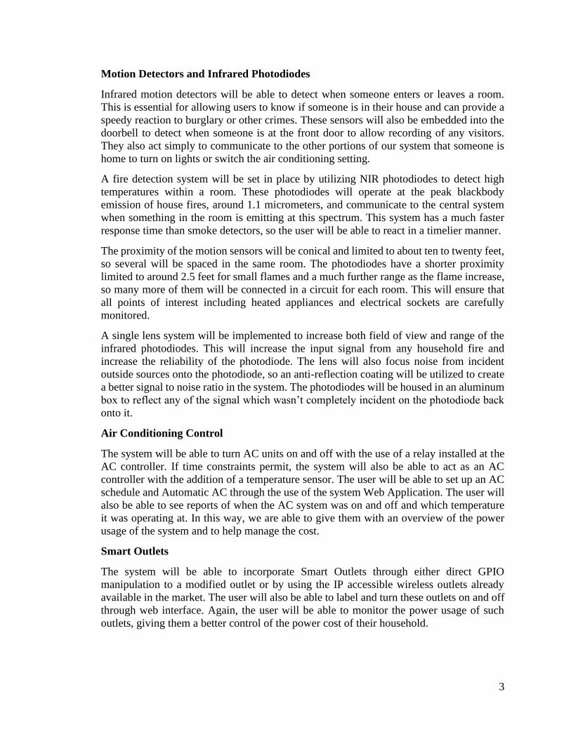
Motion Detectors and Infrared Photodiodes
Infrared motion detectors will be able to detect when someone enters or leaves a room.
This is essential for allowing users to know if someone is in their house and can provide a
speedy reaction to burglary or other crimes. These sensors will also be embedded into the
doorbell to detect when someone is at the front door to allow recording of any visitors.
They also act simply to communicate to the other portions of our system that someone is
home to turn on lights or switch the air conditioning setting.
A fire detection system will be set in place by utilizing NIR photodiodes to detect high
temperatures within a room. These photodiodes will operate at the peak blackbody
emission of house fires, around 1.1 micrometers, and communicate to the central system
when something in the room is emitting at this spectrum. This system has a much faster
response time than smoke detectors, so the user will be able to react in a timelier manner.
The proximity of the motion sensors will be conical and limited to about ten to twenty feet,
so several will be spaced in the same room. The photodiodes have a shorter proximity
limited to around 2.5 feet for small flames and a much further range as the flame increase,
so many more of them will be connected in a circuit for each room. This will ensure that
all points of interest including heated appliances and electrical sockets are carefully
monitored.
A single lens system will be implemented to increase both field of view and range of the
infrared photodiodes. This will increase the input signal from any household fire and
increase the reliability of the photodiode. The lens will also focus noise from incident
outside sources onto the photodiode, so an anti-reflection coating will be utilized to create
a better signal to noise ratio in the system. The photodiodes will be housed in an aluminum
box to reflect any of the signal which wasn’t completely incident on the photodiode back
onto it.
Air Conditioning Control
The system will be able to turn AC units on and off with the use of a relay installed at the
AC controller. If time constraints permit, the system will also be able to act as an AC
controller with the addition of a temperature sensor. The user will be able to set up an AC
schedule and Automatic AC through the use of the system Web Application. The user will
also be able to see reports of when the AC system was on and off and which temperature
it was operating at. In this way, we are able to give them with an overview of the power
usage of the system and to help manage the cost.
Smart Outlets
The system will be able to incorporate Smart Outlets through either direct GPIO
manipulation to a modified outlet or by using the IP accessible wireless outlets already
available in the market. The user will also be able to label and turn these outlets on and off
through web interface. Again, the user will be able to monitor the power usage of such
outlets, giving them a better control of the power cost of their household.
4
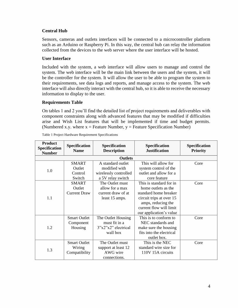
Central Hub
Sensors, cameras and outlets interfaces will be connected to a microcontroller platform
such as an Arduino or Raspberry Pi. In this way, the central hub can relay the information
collected from the devices to the web server where the user interface will be hosted.
User Interface
Included with the system, a web interface will allow users to manage and control the
system. The web interface will be the main link between the users and the system, it will
be the controller for the system. It will allow the user to be able to program the system to
their requirements, see data logs and reports, and manage access to the system. The web
interface will also directly interact with the central hub, so it is able to receive the necessary
information to display to the user.
Requirements Table
On tables 1 and 2 you’ll find the detailed list of project requirements and deliverables with
component constraints along with advanced features that may be modified if difficulties
arise and Wish List features that will be implemented if time and budget permits.
(Numbered x.y. where x = Feature Number, y = Feature Specification Number)
Table 1 Project Hardware Requirement Specifications
Product
Specification
Number
Specification
Name
Specification
Description
Specification
Justification
Specification
Priority
Outlets
1.0
SMART
Outlet
Control
Switch
A standard outlet
modified with
wirelessly controlled
a 5V relay switch
This will allow for
system control of the
outlet and allow for a
core feature
Core
1.1
SMART
Outlet
Current Draw
The Outlet must
allow for a max
current draw of at
least 15 amps.
This is standard for in
home outlets as the
standard home breaker
circuit trips at over 15
amps, reducing the
current flow will limit
our application’s value
Core
1.2
Smart Outlet
Component
Housing
The Outlet Housing
must fit in a
3”x2”x2” electrical
wall box
This is to conform to
NEC standards and
make sure the housing
fits into the electrical
outlet box.
Core
1.3
Smart Outlet
Wiring
Compatibility
The Outlet must
support at least 12
AWG wire
connections.
This is the NEC
standard wire size for
110V 15A circuits
Core

5
Table 1 Continued
Product
Specification
Number
Specification
Name
Specification
Description
Specification
Justification
Specification
Priority
Outlets
1.4
Smart Outlet
Wireless Range
The range of the
SMART Outlet
signal should be a
spherical radius of
30M
Will expand
application value
by being able to
use our device in
larger homes
Advanced
1.5
Smart Outlet
Current Sensor
The Outlet should be
able to measure the
amount of current
being drawn
Nice to have
feature for
managing energy
efficiency
Advanced
Light Switch
2.0
Lighting Control
Switch
A wireless module
with 5V output that
will control a relay
switch that will
allow for the control
of any standard
home appliance
This will allow for
the control of room
lighting, or any
appliance that is
wired to the switch.
Fans, Garbage
Disposal, etc.
Core
2.1
Lighting Control
Switch Current
Draw
The switch must
support a maximum
current draw of at
least 15 amps
This is standard for
in home outlets as
the standard home
breaker circuit trips
at over 15 amps,
reducing the
current flow will
limit our
application’s value
Core
2.2
Lighting Control
Switch Housing
The Switch housing
must be able to fit in
a 3”x2”x2” electrical
wall box
This is to conform
to NEC standards
and make sure the
housing fits into
the electrical outlet
box.
Core
2.3
Lighting Control
Switch Wiring
Compatibility
The wiring
connectors of the
switch must support
12 AWG wires
This is the NEC
standard wire size
for 110V 15A
circuits
Core
2.4
Lighting Control
Switch Range
The range of the
Lighting Control
Switch’s wireless
signal should be at
least 30m
The Range of the
signal should be a
spherical radius of
30M
Advanced
6
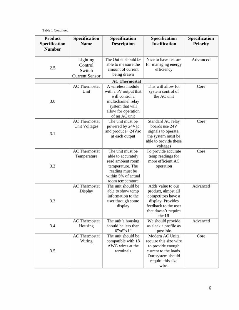
Table 1 Continued
Product
Specification
Number
Specification
Name
Specification
Description
Specification
Justification
Specification
Priority
2.5
Lighting
Control
Switch
Current Sensor
The Outlet should be
able to measure the
amount of current
being drawn
Nice to have feature
for managing energy
efficiency
Advanced
AC Thermostat
3.0
AC Thermostat
Unit
A wireless module
with a 5V output that
will control a
multichannel relay
system that will
allow for operation
of an AC unit
This will allow for
system control of
the AC unit
Core
3.1
AC Thermostat
Unit Voltages
The unit must be
powered by 24Vac
and produce ~24Vac
at each output
Standard AC relay
boards use 24V
signals to operate,
the system must be
able to provide these
voltages
Core
3.2
AC Thermostat
Temperature
The unit must be
able to accurately
read ambient room
temperature. The
reading must be
within 5% of actual
room temperature
To provide accurate
temp readings for
more efficient AC
operation
Core
3.3
AC Thermostat
Display
The unit should be
able to show temp
information to the
user through some
display
Adds value to our
product, almost all
competitors have a
display. Provides
feedback to the user
that doesn’t require
the UI
Advanced
3.4
AC Thermostat
Housing
The unit’s housing
should be less than
8”x6”x1”
We should provide
as sleek a profile as
possible
Advanced
3.5
AC Thermostat
Wiring
The unit should be
compatible with 18
AWG wires at the
terminals
Modern AC Units
require this size wire
to provide enough
current to the loads.
Our system should
require this size
wire.
Core

7
Table 1 Continued
Product
Specification
Number
Specification
Name
Specification
Description
Specification
Justification
Specification
Priority
3.6
AC Thermostat
Wireless Range
The range of the
unit’s wireless
signal should be a
spherical radius of
30m
Will expand
application value
by being able to use
our device in larger
homes
Advanced
Door Lock
4.0
Door Lock
Control System
A wireless door
lock that can
communicate and
receive command
from the system
controller
This door lock will
be part of the safety
components of the
system.
(This Item Is
Currently Tabled)
Wish List
Optical Flame Detector
5.0
Fire Detection Infrared
photodiodes will
alert any user of fire
or exceedingly high
temperatures
Alerts any user of
potential danger
Core
5.1
Fire Detector
Range and Field
of View
A single lens
system will focus
incident rays onto
the photodiode
extending sensor
proximity and FOV.
Should have a range
of 5m
Less photodiodes
are necessary, and
the monitored area
will be larger
Advanced
5.2
Fire Detector
Optical Noise
Reduction
An anti-reflection
coating will be
applied to the lens
to increase signal
quality in the
infrared spectrum.
A band pass filter
may be applied for
optimal SNR.
The system will be
more reliable
because outside
sources such as the
sun will not trigger
false positives as
easily
Wish List
5.3
Fire Detector
Housing
The housing for this
unit should be no
more than 4”x4”x2”
This is to provide
as sleek a profile as
possible so that the
sensor can be
installed anywhere
Advanced
8
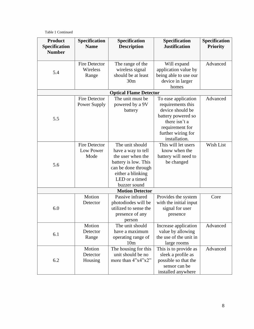
Table 1 Continued
Product
Specification
Number
Specification
Name
Specification
Description
Specification
Justification
Specification
Priority
5.4
Fire Detector
Wireless
Range
The range of the
wireless signal
should be at least
30m
Will expand
application value by
being able to use our
device in larger
homes
Advanced
Optical Flame Detector
5.5
Fire Detector
Power Supply
The unit must be
powered by a 9V
battery
To ease application
requirements this
device should be
battery powered so
there isn’t a
requirement for
further wiring for
installation.
Advanced
5.6
Fire Detector
Low Power
Mode
The unit should
have a way to tell
the user when the
battery is low. This
can be done through
either a blinking
LED or a timed
buzzer sound
This will let users
know when the
battery will need to
be changed
Wish List
Motion Detector
6.0
Motion
Detector
Passive infrared
photodiodes will be
utilized to sense the
presence of any
person
Provides the system
with the initial input
signal for user
presence
Core
6.1
Motion
Detector
Range
The unit should
have a maximum
operating range of
10m
Increase application
value by allowing
the use of the unit in
large rooms
Advanced
6.2
Motion
Detector
Housing
The housing for this
unit should be no
more than 4”x4”x2”
This is to provide as
sleek a profile as
possible so that the
sensor can be
installed anywhere
Advanced

9
Table 1 Continued
Product
Specification
Number
Specification
Name
Specification
Description
Specification
Justification
Specification
Priority
Motion Detector
6.3 Motion
Detector Low
Power Mode
The unit should
have a way to tell
the user when the
battery is low. This
can be done
through either a
blinking LED or a
timed buzzer
sound
This will let
users know
when the battery
will need to be
changed
Wish List
6.4 Motion
Detector
Power
Supply
The unit must be
powered by a 9V
battery
To ease
application
requirements
this device
should be
battery powered
so there isn’t a
requirement for
further wiring
for installation
Advanced
Table 2 Project Software Requirements Specifications
Web Server Product
Specification
Number
Specification
Name
Specification
Description
Specification
Justification
Specification
Priority
7.0
System
Management
Users can manage
system through a web
page
This will allow the
user to manage the
system in a fast way
Core
7.1 Security Unauthorized access
should be prevented
This will allow the
system to be secure
Core
7.3
Hosting Web server will be
hosted within a third-
party service
This will prevent the
user of the need to
manage a server
Core
7.4
Capacity The system should be
able to support a
minimum of 5 users
and have space for
growth
This will allow the
system to be scalable
Core
7.4
Log The web interface
should provide a log
of who/what triggered
the sensors
This will allow the
user to have greater
control of the system
Advanced
Feature
10
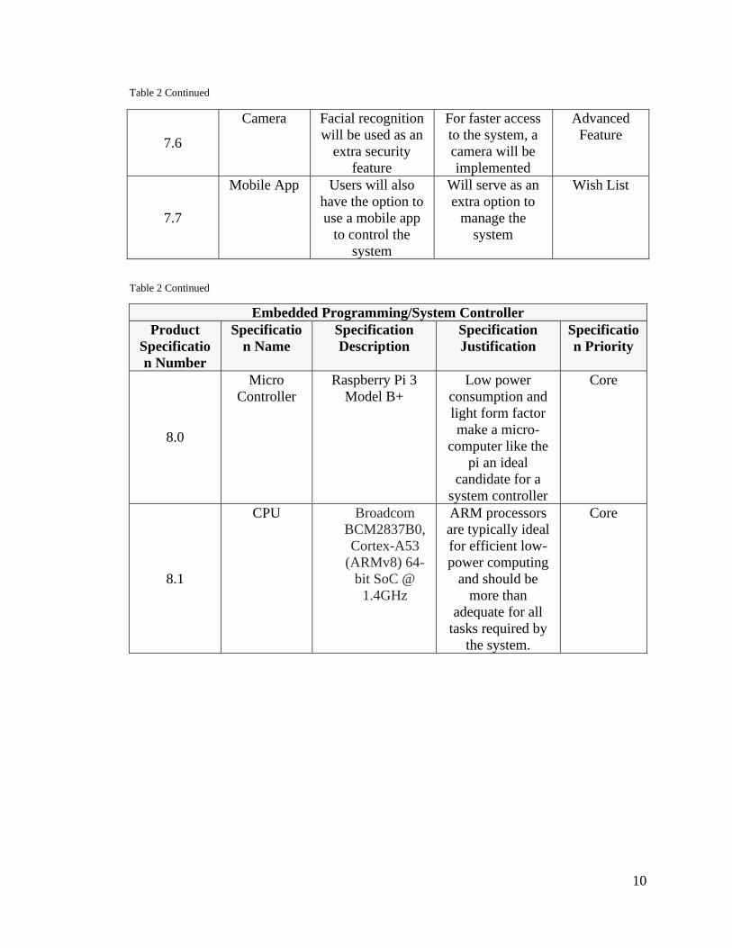
Table 2 Continued
7.6
Camera Facial recognition
will be used as an
extra security
feature
For faster access
to the system, a
camera will be
implemented
Advanced
Feature
7.7
Mobile App Users will also
have the option to
use a mobile app
to control the
system
Will serve as an
extra option to
manage the
system
Wish List
Table 2 Continued
Embedded Programming/System Controller
Product
Specificatio
n Number
Specificatio
n Name
Specification
Description
Specification
Justification
Specificatio
n Priority
8.0
Micro
Controller
Raspberry Pi 3
Model B+
Low power
consumption and
light form factor
make a micro-
computer like the
pi an ideal
candidate for a
system controller
Core
8.1
CPU Broadcom
BCM2837B0,
Cortex-A53
(ARMv8) 64-
bit SoC @
1.4GHz
ARM processors
are typically ideal
for efficient low-
power computing
and should be
more than
adequate for all
tasks required by
the system.
Core
11
Table 2 Continued
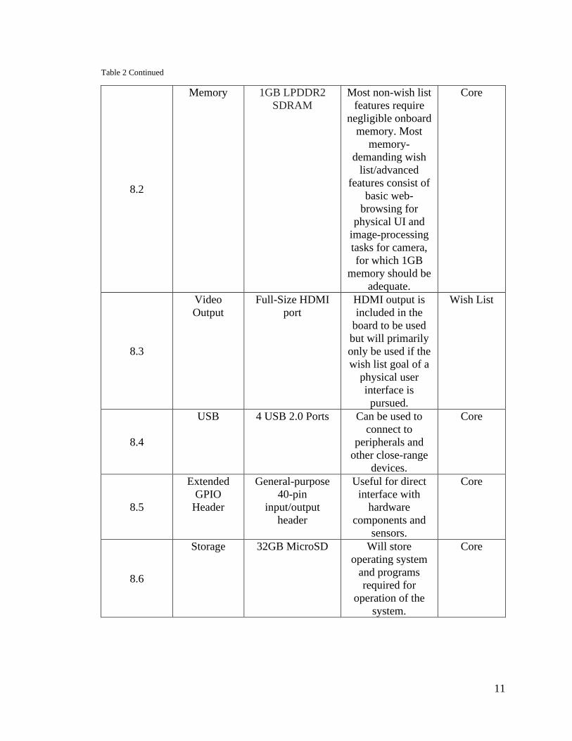
8.2
Memory 1GB LPDDR2
SDRAM
Most non-wish list
features require
negligible onboard
memory. Most
memory-
demanding wish
list/advanced
features consist of
basic web-
browsing for
physical UI and
image-processing
tasks for camera,
for which 1GB
memory should be
adequate.
Core
8.3
Video
Output
Full-Size HDMI
port
HDMI output is
included in the
board to be used
but will primarily
only be used if the
wish list goal of a
physical user
interface is
pursued.
Wish List
8.4
USB 4 USB 2.0 Ports Can be used to
connect to
peripherals and
other close-range
devices.
Core
8.5
Extended
GPIO
Header
General-purpose
40-pin
input/output
header
Useful for direct
interface with
hardware
components and
sensors.
Core
8.6
Storage 32GB MicroSD Will store
operating system
and programs
required for
operation of the
system.
Core

12
Table 2 Continued
8.7
Wireless
Networking
2.4GHz and
5GHz IEEE
802.11.b/g/n/ac
wireless LAN,
Bluetooth 4.2,
BLE
Provides a wide
range of wireless
networking
capabilities, Wi-Fi
is necessary for
project as
described and
Bluetooth has
potential use as
well.
Core
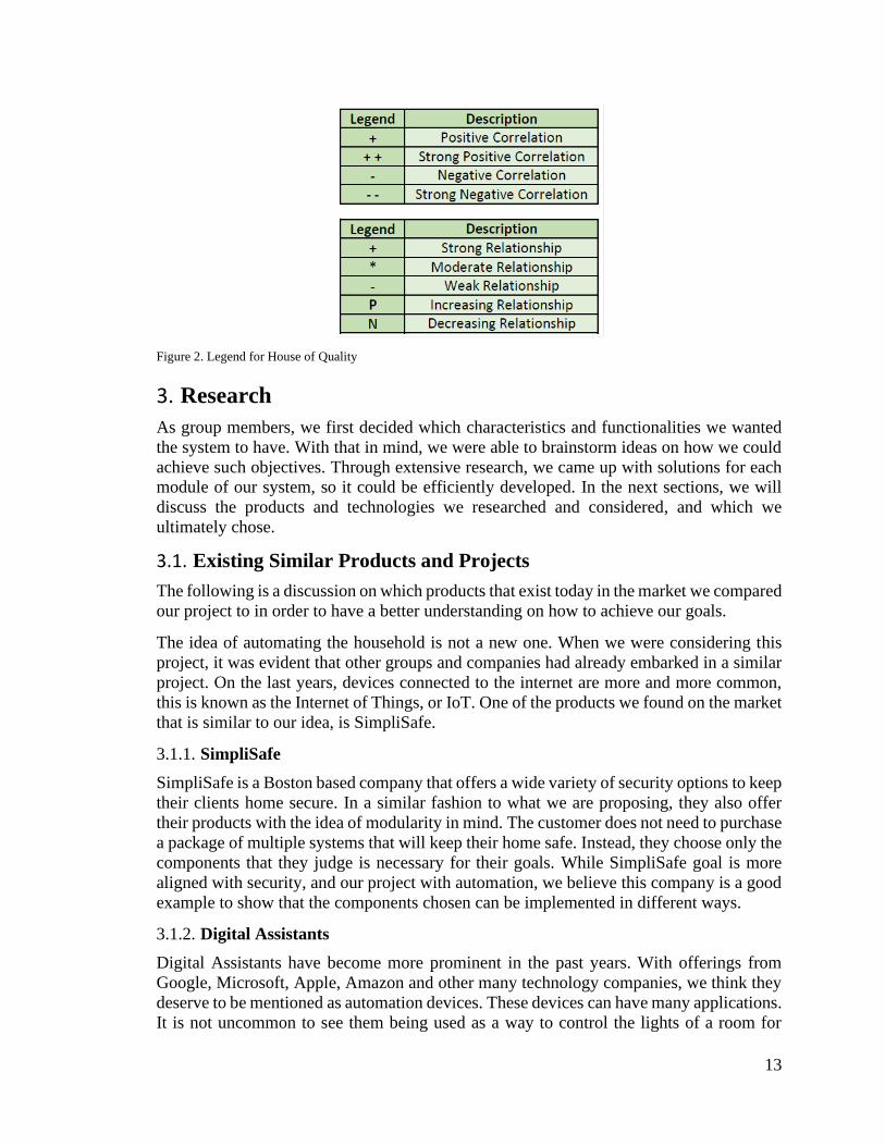
2.4. House of Quality
The House of Quality is a diagram utilized to tie together the needs of the consumers with
the requirements specifications of the product being developed. The House of Quality for
our project can be seen in figure 1, and the legend for it on figure 2. With this diagram, we
can see how the customer needs relate with the specifications of our project.
Figure 1. House of Quality
13
Figure 2. Legend for House of Quality
3. Research
As group members, we first decided which characteristics and functionalities we wanted
the system to have. With that in mind, we were able to brainstorm ideas on how we could
achieve such objectives. Through extensive research, we came up with solutions for each
module of our system, so it could be efficiently developed. In the next sections, we will
discuss the products and technologies we researched and considered, and which we
ultimately chose.
3.1. Existing Similar Products and Projects
The following is a discussion on which products that exist today in the market we compared
our project to in order to have a better understanding on how to achieve our goals.
The idea of automating the household is not a new one. When we were considering this
project, it was evident that other groups and companies had already embarked in a similar
project. On the last years, devices connected to the internet are more and more common,
this is known as the Internet of Things, or IoT. One of the products we found on the market
that is similar to our idea, is SimpliSafe.
3.1.1. SimpliSafe
SimpliSafe is a Boston based company that offers a wide variety of security options to keep
their clients home secure. In a similar fashion to what we are proposing, they also offer
their products with the idea of modularity in mind. The customer does not need to purchase
a package of multiple systems that will keep their home safe. Instead, they choose only the
components that they judge is necessary for their goals. While SimpliSafe goal is more
aligned with security, and our project with automation, we believe this company is a good
example to show that the components chosen can be implemented in different ways.
3.1.2. Digital Assistants
Digital Assistants have become more prominent in the past years. With offerings from
Google, Microsoft, Apple, Amazon and other many technology companies, we think they
deserve to be mentioned as automation devices. These devices can have many applications.
It is not uncommon to see them being used as a way to control the lights of a room for

14
example. Most of the time however, these assistants, are merely a middle man between the
device being controlled and who is controlling such device. For our project, we are aiming
to eliminate this step, to reduce the cost of implementing such system. We believe that this
will allow the control of such systems to occur more fluidly and it also will consolidate the
number of different controllers into a single system.
3.1.3. Raspberry Pi Projects
Many companies have opted for automated room units to conserve electricity for both
economic and environmental reasons. One example specifically resembles our project with
its usage of both a Raspberry Pi module as a central hub component and passive infrared
sensors for motion detection which was published in 2018. The goal of the observed project
is to connect home appliances in a communication network with one another using the
internet. The Raspberry Pi module was selected for both its functionalities and low cost of
about $25-30 [1]. An operating system is necessary for the Raspberry Pi to perform
essential functions, and all operating systems available for it utilize Linux. The specific
operating system used by the study is called Raspbian, and it was chosen because it is the
officially supported operating system by the Raspberry Pi Foundation [1].
The Raspberry Pi has many different specifications which make it optimal for this type of
project. The presence of a Micro USB power port, which can give an input current of 2
amps, allows for an easy power source for the system. The 40 pin GPO header allows for
many inputs and outputs to communicate with both the PIR sensors and the light and AC
controls. The 10/100Mbps ethernet ports allow for internet connectivity to allow users to
control the system remotely. The MicroSD card slot lets users have variable input memory
for scaling of simple to complex systems based on the size of the automation system. The
Raspberry Pi has ample processing speed for this application with its 700MHz processor.
Ease of installation is also a large reason that the Raspberry Pi was chosen for this project.
3.2. Relevant Technologies
The following is a discussion on the technologies already available in the market, the
products that were considered, and the reasoning on why they were ultimately chosen to
be used in our project.
3.2.1. AC Thermostat
The Goal
The HVAC system in a home is probably the most impactful in terms of the Home’s energy
efficiency and comfort. Maintaining strict user control of this system is crucial for the
Home Automation experience. With our product, users will be able set a target temperature,
create a system schedule, and operate the system from any number of mobile devices. This
is not the first smart thermostat, there are many of these devices already in the market, our
goal is to make these devices cheaper and more accessible. The following table illustrates
some the highest rated Thermostats under $200, their features, and retail prices.

15
Table 3 Market Analysis of Wireless Thermostats
Market Analysis Product Name Feature 1 Feature 2 Feature 3 Price
Emerson Sensing
ST55
Flexible
Scheduling
Geofencing Proprietary App $129.99
Honeywell
Programable Wi-
Fi Thermostat
RTH6580WF
Flexible
Scheduling
Local Weather,
System Alerts
Proprietary App $79.99
Nest Learning
Thermostat
T3007ES
Auto Scheduling Adjusts for Local
Weather Changes
Proprietary App $189.99
Our Product Flexible
Scheduling
System Alerts Web Application Target Price
$50
The Wiring
The typical control wiring for a conventional central air conditioning system includes a
thermostat, a condenser, and an air handler with a heat source. The Thermostat typically
consists of 5 terminals. One is the 24v hot feed from the control step down transformer that
will power the relay or complete the AC circuit board. This is typically a Red wire. The
White terminal provides power for the heating element of the AC unit. The Green terminal
powers the blower fan in the air handler. The Yellow terminal is usually the control. This
is the terminal we would need to take over from the thermostat to turn the AC on and off.
The Black Terminal is the common ground. To achieve the level of control we would like
with our AC system controller we will need a few items in our circuit. We will need an
AC-DC Power Supply Module that goes from 120v to 24v to power the relays and a
stepdown voltage generator to go from 24v to 3.3-5v to power the wireless MCU.
Figure 3. Wiring of an AC Thermostat

16
The Power Supply
There are hundreds of power supply modules that can work for this system in the market,
but we will only consider the most inexpensive power supplies available through reliable
online retailers. The first candidate is the DAOKI AC-DC Power Supply Module AC 85-
265V to DC 24V 6A Switching Power Supply Board Model XK-2412-24. This module is
readily available, has overvoltage protection, takes in AC 85-265V at 50 or 60Hz and
outputs 24V at 4-6A. It’s rated output power is 100W which is more than enough to power
our system and price is a little less than $10.
The next candidate for our Power Supply module is the TOFKE AC - DC Power Supply
Module DC 24V 4A/3.3V 1A Dual Output AC 90-265V to 24V 3.3V 120W Industrial
Power Module Isolated Power Transformer. This module provides a lot of the same specs
as the previous Daoki but with the added benefit of dual output. By using the 3.3V output
from this power supply, we will no longer need a stepdown voltage converter, this of course
is reliant on the MCU only needing 3.3V power. Due to the extra feature this module is a
little pricier at $13.
The Stepdown Voltage Regulator
One possible module that will work when using a single 24V output Power Supply is this
DZS Elec 2PCS LM2596 DC-DC Step Down Variable Volt Regulator Input 3.2V-40V
Output 1.25V-35V Adjustable Buck Converter Electronic Voltage Stabilizer Power Supply
Module. This covereter is 92% efficient, has an output ripple of less than 30 mV, compact
with dimensions of 4.3x2.1x.1.4cm, and operates at temperatures up to 85C. The best thing
about this regulator is its adjustability. By turning the potentiometer one can output
whatever voltage desired from 3.3V to 35V. Two converters cost about $7.
Another option is the Wolfwhoop PW-D Control Buck Converter 6-24V to 5V 1.5A Step-
Down Regulator Module Power Inverter Volt Stabilizer. This Buck Converter is tiny, the
board is 1.7x5.5cm and the price is reasonable, 4 for $10, however the ouput is not
adjustable which means this will only work for an MCU that takes 5V as its input.
The Wireless Microcontroller Unit
The ESP8266 ESP-12E WiFi Microcontroller USB Development Board is a very popular,
reliable wireless module. The ESP8266 is a low-cost Wi-Fi chip with full TCP/IP stack
and MCU. The ESP-12E module is a shielded breakout board that combines the ESP8266
with 4MB of flash and a PCB antenna. This development board integrates the ESP-12E
module with a CH340G USB TTL adapter chip, power converter circuitry, buttons, and
breadboard compatible pin header. The default firmware can add WIFI capability to
another microcontroller over a serial interface. The module comes in around $5. There is
plenty of support for integrating the ESP8266 into all kinds of systems, but this model is
missing some key features like a relay system to turn the 24V terminals on/off. Choosing
this board would mean we would need to design those relays ourselves.
Then comes the LinkSprite 211201004 Link Node R4 Arduino-Compatible Wi-Fi Relay
Controller. This module is powered by the same ESP8266 above but with the added benefit
of 4 controllable relays. This will allow us to wirelessly control the 4 needed terminals for
the AC controller. The module will be pricey, at a cost of $12 but it should reduce design
17
time and prototype difficulty because we will not need design the relay system ourselves.
This system is powered by a 5V input with 1A max draw.
The Temperature Sensor
To know when to power the AC and for feedback so that users know the roomtemperature
and for automatic setting we will need a compatible temperature sensor. A cheap and easily
available option is the DHT11. This is the NOYITO DHT11 Digital Temperature Humidity
Sensor Module. There are many manufactures of this device but this is one available in
amazon. It is powered by a 5V input with .3mA draw and has a digital output that
communicates using I2C. This device measure relative humidity from 20-90% with a
standard deviation of 5% and temperature measurements from 0-50C with a deviation of
2C. This sensor is usually priced around $3 each. Our other option is the DHT22. This is a
more accurate sensor compared to the DHT11, but with better accuracy comes a higher
price. It is made by many manufacturers and costs around $6.
The Verdict
For this AC Controller Unit component we will be using the DAOKI AC-DC Power Supply
to power the system, the Wolfwhoop PW-D Control Buck Converter to power the
LinkSprite Wi-Fi Relay Controller and the DHT22 temperature sensor. These components
provide the best combination in terms of price and compatibility and should be enough to
meet the requirements of our AC control unit. We went with the DHT22 because to provide
better energy efficiency our system needs to be as accurate as possible with sensor readings.
The Wolfwhoop should be sufficient to power the MCU and the sensor. Budget for the
hardware costs will need to be around $30.
3.2.2. Household Lighting
The Goal
Controlled lighting is a key feature necessary to produce optimum energy efficiency inside
a home. We want a system that can automatically manage the user’s lighting needs by using
the array of sensors we provide to reduce waste in the system. The lights should only be
on when needed. To provide these energy saving features, without taking complete control
from the user we will integrate wireless light switches into the system. With our product,
users will be able to schedule the auto light feature, turn on/off room lights manually, and
operate the system from any number of mobile devices. This is not the first smart switch,
there are many of these devices already in the market, our goal is to make these devices
cheaper and more accessible. The following table illustrates some the highest rated smart
switches under $40, their features, and retail prices.

18
Table 4 Market Analysis of Wireless Light Switches
Market Analysis
Product Name Feature 1 Feature 2 Feature 2 Price
TreatLife WiFi
Smart Switch
Flexible
Schedule,
Timer
Proprietary
App
Alexa, Google
Assistant
Compatible
$19.99
Kasa Smart Light
HS200
Flexible
Schedule,
Timer
Proprietary
App
Alexa, Google
Assistant
Compatible
$39.99
Eoce Smart Light
Switch
Flexible
Schedule,
Timer
Proprietary
App
Alexa, Google
Assistant
Compatible
$16.45
Our Smart Light
Switch
Flexible
Schedule,
Timer
Web
Application
Auto Motion
Sensing On/Off
Target Price
$15
The Wiring
Household electronics, switches and outlets have to follow strict codes and guidelines that
require certain design standards and safety measures to be present. These codes can differ
state to state and even change depending on the municipality the building is in. We will be
following the National Electrical Code (NEC) set by the National Fire Protection
Association (NFPA). The NEC sets the foundation for electrical safety in residential,
commercial, and industrial occupancies. The latest edition of this trusted Code presents the
latest comprehensive regulations for electrical wiring, overcurrent protection, grounding,
and installation of equipment. (NFPA.ORG) These standards have been adopted in all 50
states and for any design or component that we will use for this project, strict adherence to
these measures should be followed. To make things easier we will not try to reinvent the
wheel by designing our own light switch. To design a wireless device that will allow us to
automate room lighting we will use a standard 3-way home light switch like the model
5603-2W from Levinton and add a controllable relay switch and programmable wireless
MCU like the ESP8266 to send signals from the server application to the device. The relay
and the light switch will be wired in a three-way configuration. This will provide the best
usability for our product. This will mean that both the light switch and relay will work as
a toggle independent of the other. To achieve this creation, we will need a few components
in the device:
• Power Supply capable of taking 120V AC to 3.3V to 5V DC depending on the
MCU-Relay module used
• Wireless MCU that can communicate through an in home WIFI network and takes
TCP/HTTP commands
• Relay system that is trigger by a 3.3-5V signal with at least 2 channels switching
and capable of supporting 10 amps or more
• A current sensor to measure when the light is on.

19
The MCU and Relay System
In researching the AC System Controller, we decided to go with the ESP8266 MCU. We
will stick with using the ESP8266 with most of our wireless components and sensors.
Unlike the AC Controller we will not be needing a four-channel relay array, so we can use
something like ESP-01S WIFI relay module. This module comes with a relay with two
switching nodes. This is perfect for our application because we can use this to toggle the
light switch or open the circuit and ensure the light switch stays off. This board requires 5-
volt power supply and uses about 1W which means we should aim for a power supply that
can produce 5V with anything greater than 1A.
Power Supply
One possibility for the power supply comes from the brand Hi-Link. The HLK-PM line of
power modules meets UL and CE (Conformité Européenne) requirements, takes in all
standard voltage inputs (AC: 90 ~ 264V), has low ripple and low noise, output overload
and short circuit protection, High efficiency, and high-power density. This product is
designed to meet the requirements of EMC (Electromagnetic Compatibility standards) and
Safety Test. It also has low power consumption, environmental protection, no-load loss
<0.1W. (Hi-Link) Which really just means we can trust the dependability of this device to
do what it says it will do and safely. The HLK-PM comes in 3 configurations: 3.3V, 5V,
and 12V outputs and can be purchased for around $3-7.
Another candidate is the ESHION AC-DC 5V 1A Switching Power Supply Board. This
board is a little more exposed but can be used solderless as it has AC input pins and DC
output pins. It provides similar safety measures and standards as the Hi-Link module but
can support up to 1A. The Hi-Link can only support a max of .6A. This module cost 5-7$.
The ESHION measures 3.8X1.8X1.6cm which is comparable to the HLK-PM01 at 3.4 x 2
x 1.5cm so we are not gaining much in volume.
Current Sensor
Due to the three-way circuit between the paddle switch and the relay module, there is no
way to know if the light is on or off by observing the position of the relay switch. For user
feedback and so that we can display when the room light is on we will need a current sensor
to measure the load. One possible solution is to integrate the ACS712 sensor. This sensor
Outputs 100mA/V so not only does it measures whether there is current passing through
or not it also measures the amount of current. The sensor is available to support max
currents of 5A, 20A, and 30A. Since the relay system we are using will have a 10A limit
we will look at sensors that support 10A or more. This sensor has a total output error 1.5%
at TA = 25°C, Internal conductor resistance 1.2 mΩ, powered by 5V, and works at
Temperatures 40°C to 85°C, with an analog signal output. The cost of this sensor can range
from 2-$10. Many of the other sensors available are either variants of this model but made
by other manufacturers, or too expensive, for amp ranges we don’t need to consider, or too
bulky, using magnets around the cable to test for current indirectly.
The Verdict
Due to price and availability the best candidate for the power supply will have to be the
HLK-PM01 from Hi-Link. Most smart switches in the market are available for around $15
20
which means we need to keep our HW available at or below market value to be competitive.
Using a Power supply that costs a third of our target retail price is not very feasible however
if after testing it is determined that more than .6A is needed to power all the 5V components
then we will have to consider switching to the more expensive PSU. The MCU/Relay board
estimated at $3, the PSU at $3, the current sensor at $2, and the light switch estimated to
be around $4 will make this device cost around $12. Granted it will be difficult to make a
profit when the hardware costs almost as much as our target selling price, but these numbers
are retail acquisitions. If we can come under our desired budget with retail priced
components than we should be able to drastically reduce our costs when we order directly
from the manufacturer should we decide to produce these items.
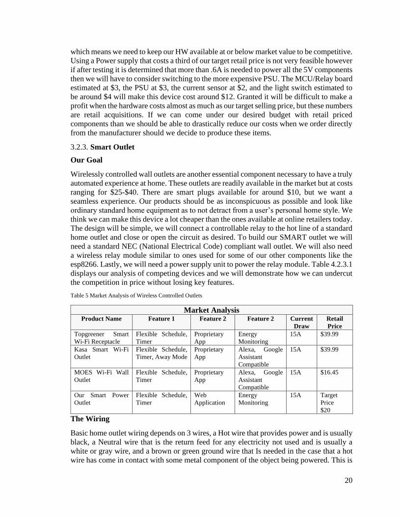
3.2.3. Smart Outlet
Our Goal
Wirelessly controlled wall outlets are another essential component necessary to have a truly
automated experience at home. These outlets are readily available in the market but at costs
ranging for $25-$40. There are smart plugs available for around $10, but we want a
seamless experience. Our products should be as inconspicuous as possible and look like
ordinary standard home equipment as to not detract from a user’s personal home style. We
think we can make this device a lot cheaper than the ones available at online retailers today.
The design will be simple, we will connect a controllable relay to the hot line of a standard
home outlet and close or open the circuit as desired. To build our SMART outlet we will
need a standard NEC (National Electrical Code) compliant wall outlet. We will also need
a wireless relay module similar to ones used for some of our other components like the
esp8266. Lastly, we will need a power supply unit to power the relay module. Table 4.2.3.1
displays our analysis of competing devices and we will demonstrate how we can undercut
the competition in price without losing key features.
Table 5 Market Analysis of Wireless Controlled Outlets
Market Analysis Product Name Feature 1 Feature 2 Feature 2 Current
Draw
Retail
Price
Topgreener Smart
Wi-Fi Receptacle
Flexible Schedule,
Timer
Proprietary
App
Energy
Monitoring
15A $39.99
Kasa Smart Wi-Fi
Outlet
Flexible Schedule,
Timer, Away Mode
Proprietary
App
Alexa, Google
Assistant
Compatible
15A $39.99
MOES Wi-Fi Wall
Outlet
Flexible Schedule,
Timer
Proprietary
App
Alexa, Google
Assistant
Compatible
15A $16.45
Our Smart Power
Outlet
Flexible Schedule,
Timer
Web
Application
Energy
Monitoring
15A Target
Price
$20
The Wiring
Basic home outlet wiring depends on 3 wires, a Hot wire that provides power and is usually
black, a Neutral wire that is the return feed for any electricity not used and is usually a
white or gray wire, and a brown or green ground wire that Is needed in the case that a hot
wire has come in contact with some metal component of the object being powered. This is

21
a safety measure to reduce the risk of shock in case of a short circuit. So to build this
component we will need the relay to be able to open the Hot wire so that any failure in the
system will ensure no power goes to the outlet. The standard home outlet is connected to a
15A breaker system, which means our relay must be able to perform at 15A. Getting a relay
that supports less power will severely limit the capabilities of the outlet. A relay that
supports more power would be overkill because any load that would draw more than 15
amps would trigger the breaker switch. Therefore, some of the previous relay modules we
have studied will not work for this part of the project.
The Relay Module and MCU
Taking an ESP8266 and a 15A 5V relay and creating our own circuit design is a possibility,
however this would put far too much of a design and compliance burden on our team, so
we will try our best to stick with readymade components that will only require
programming and integration. This is very important to maintain the highest safety
standards when dealing with high voltage and current. So far, the only ESP8266 relay
module that we have found to support up to 15A at 120V is this one from Olimex.
Unfortunately, the desire to use prebuilt modules for our project will mean we will have to
pay top dollar for some components. This board will cost about $16 shipped, add in a PSU
and our total hardware cost is hovering around $21, which is still under the retail price of
the competition, but we will have minimal profit margins unless we manage to reduce the
price of a prebuilt module like this one. In the Olimex’s defense, it is a great little piece of
technology and has some key desirable features. This includes:
• Relay 10A/250VAC (15A/120VAC 15A/24VDC) with connector and status LED
• Big button for easier access to UART mode
• Power jack for +5V external power supply
• UEXT connector
• Row of 16 pin holes at 0.1" step with all ESP8266 signals accessible; male-male
16-pin connector included
• 4 mounting holes
Not to mention the ESP8266EX features like:
• 2MB (16Mb) SPI flash memory
• Power LED
• User-programmable LED
• SMT jumpers for different boot modes (FLASH, UART, SDO)
• PCB antenna
• UEXT pads for easier access to UART interface
• Pads for a U.FL antenna connector (for external antenna)
• 22 pin holes for easier access to processor pins
• OSHW design (Open Source Hardware Association)
All of this comes in a very compact package measuring 5.7x5x2cm and should fit easily
behind the outlet. Everything considered, this board may be worth the price and if costs
end up being too high, another possibility is to take one of the cheaper ESP8266 relay board

22
and upgrading the relay on it, this will undoubtedly result in a less reliable device, and may
result in safety standards not being followed.
Power Supply
We will try to use the same power supply for each component of our project so that we are
able to make orders in bulk. For this reason, we will use the HLK-PM01 from Hi-Link that
was researched in the Smart Lighting section of this document. As said before, The HLK-
PM line of power modules meets UL and CE (Conformité Européenne) requirements, takes
in all standard voltage inputs (AC: 90 - 264V), has low ripple and low noise, output
overload and short circuit protection, High efficiency, and high-power density. This
product is designed to meet the requirements of EMC (Electromagnetic Compatibility
standards) and Safety Test. It also has low power consumption, environmental protection,
no-load loss <0.1W. (Hi-Link). The HLK-PM01 is the model that outputs 5V and costs
around $3 each. Since the ESP8266EX operates at an average of 80mA we are pretty
confident that the 600mA the PSU can supply should be enough for our application.
The Verdict
This pretty much sums up the major components we’ll require for our version of the
SMART Outlet. Total price for the HW is around $21, however this price is not a good
representation of what the actual cost of making a device such as this should be. Consider
that we will be using the Olimex ESP8266-EVB, an evaluation board meant for testing and
prototyping, not to be placed in a final product. If we can have a manufacture make boards
like the ESP-01S WIFI relay module, researched in the Home Lighting section, with an
upgraded 15A relay at a cost of around $3/board than you’re looking at a device that costs
less than $10 to produce and can easily retail for $20, undercutting the competition by at
least a 25% discount.
3.2.4. Wireless Technologies
3.2.4.1. Wi-Fi
Due to the large number of devices generally associated with putting together a home-
automation system, the prospect of achieving communication between said devices via
wired networking schemes such as Ethernet has the potential to become cumbersome and
expensive. To that end, the numerous wireless networking protocols available on the
market today serve as an apt solution to this problem. In particular, the viability of standard
Wi-Fi and the ZigBee wireless networking protocol were examined in-detail for use in this
project.
Wi-Fi is a familiar and ubiquitous networking protocol that is already deployed in most
homes, businesses, and other organizations which maintain a local-area-network with
Internet connectivity. Wi-Fi is versatile and offers bandwidth suitable for most personal
computer networking tasks. However, since Wi-Fi was never designed with low-power use
cases in mind, it is not particularly suited for any applications where the networked sensor
or component is expected to operate on battery-power for extended periods of time, and
even if the issue of battery life is avoided by using wall-outlet power, numerous non-
battery-operated Wi-Fi enabled components have the potential to significantly decrease the
energy efficiency of the system as a whole. Power consumption will vary depending on the

23
design of the device in question and the usage-characteristics of said device, but generally
can be expected to vary from 4mW to 324mW, with the most inefficient use-cases being
those which require the device be ‘woken up’ from a low-power state for frequent, short
transmissions(Energy Consumption Analysis for Bluetooth, Wi-Fi and Cellular Networks,
Rahul Balani).
Due to the fact that the home’s control systems are to be designed so that they are accessible
even while the user is away from the home, some type of Internet connectivity is necessary.
In such a case, only the system’s hub would need Internet connectivity, which could very
well be achieved via wired Ethernet. However, if wired connections are not an option, Wi-
Fi is the only wireless solution which allows for connection to an Internet-facing LAN and,
conveniently, the Raspberry Pi which is to serve as the hub for the system does possess
onboard wireless networking hardware which is compatible with Wi-Fi standards.
3.2.4.2. ZigBee
ZigBee is another technology of primary interest for use in in-home communication
between sensors and devices which are part of the system. The primary advantages of
ZigBee stem from significantly lower power-consumption as compared to Wi-Fi, the fact
that devices connected on a ZigBee network are not exposed to the Internet through a LAN
(reducing the chance of individual elements in the system being compromised by a third
party via the internet), and from the number of off-the-shelf home automation devices
which are compatible by default with the protocol. The primary drawback of ZigBee as
compared to Wi-Fi can be found in much lower data-transfer rates as compared to a more
high-volume oriented technology such as Wi-Fi, but for a use case in home-automation,
where communications between devices will typically be measured in bytes, the reduced
bandwidth is of little concern. Another drawback of ZigBee is that specialized radio
hardware is required to receive the majority of the advertised gains in power efficiency and
in most cases ZigBee hardware is somewhat more expensive than comparable standalone
Wi-Fi networking modules.
Given the lower cost of standalone Wi-Fi modules (approximately a dollar each, vs. three
dollars or more for an equivalent ZigBee hardware solution) and the familiarity of the
protocol involved, we have opted to use Wi-Fi as the primary protocol for all of our
wireless networking, with the caveat that an implementation via ZigBee would certainly
be possible and would likely result in an improved power-consumption profile for the
system at large.
3.2.4.3. WPA Supplicant
WPA_Supplicant is a cross-platform supplicant with support for most Wi-Fi technologies
including WPA2 and which can be configured to allow for direct peer-to-peer Wi-Fi
access. WPA_Supplicant is available on an overwhelmingly wide variety of Linux and
Unix-based systems, and even offers windows support. WPA_Supplicant oftentimes
comes pre-installed on Unix based systems which can be expected to be carrying out
wireless networking tasks, as is the case for most distros designed to run on the pi.
Configuration can be carried out either via command-line configuration files or via
graphical user interface front-ends. The degree of configurability presented by
WPA_Supplicant, coupled with the detailed and extensive documentation and user-created
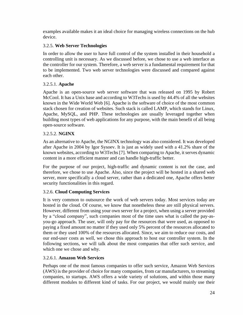
24
examples available makes it an ideal choice for managing wireless connections on the hub
device.
3.2.5. Web Server Technologies
In order to allow the user to have full control of the system installed in their household a
controlling unit is necessary. As we discussed before, we chose to use a web interface as
the controller for our system. Therefore, a web server is a fundamental requirement for that
to be implemented. Two web server technologies were discussed and compared against
each other.
3.2.5.1. Apache
Apache is an open-source web server software that was released on 1995 by Robert
McCool. It has a Unix base and according to W3Techs is used by 44.4% of all the websites
known in the Wide World Web [6]. Apache is the software of choice of the most common
stack chosen for creation of websites. Such stack is called LAMP, which stands for Linux,
Apache, MySQL, and PHP. These technologies are usually leveraged together when
building most types of web applications for any purpose, with the main benefit of all being
open-source software.
3.2.5.2. NGINX
As an alternative to Apache, the NGINX technology was also considered. It was developed
after Apache in 2004 by Igor Sysoev. It is just as widely used with a 41.2% share of the
known websites, according to W3Techs [7]. When comparing to Apache, it serves dynamic
content in a more efficient manner and can handle high-traffic better.
For the purpose of our project, high-traffic and dynamic content is not the case, and
therefore, we chose to use Apache. Also, since the project will be hosted in a shared web
server, more specifically a cloud server, rather than a dedicated one, Apache offers better
security functionalities in this regard.
3.2.6. Cloud Computing Services
It is very common to outsource the work of web servers today. Most services today are
hosted in the cloud. Of course, we know that nonetheless these are still physical servers.
However, different from using your own server for a project, when using a server provided
by a “cloud company”, such companies most of the time uses what is called the pay-as-
you-go approach. The user, will only pay for the resources that were used, as opposed to
paying a fixed amount no matter if they used only 5% percent of the resources allocated to
them or they used 100% of the resources allocated. Since, we aim to reduce our costs, and
our end-user costs as well, we chose this approach to host our controller system. In the
following sections, we will talk about the most companies that offer such service, and
which one we chose and why.
3.2.6.1. Amazon Web Services
Perhaps one of the most famous companies to offer such service, Amazon Web Services
(AWS) is the provider of choice for many companies, from car manufacturers, to streaming
companies, to startups. AWS offers a wide variety of solutions, and within those many
different modules to different kind of tasks. For our project, we would mainly use their
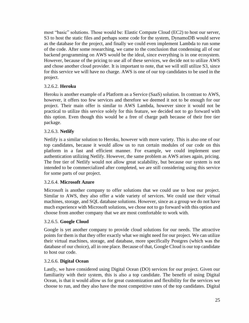
25
most “basic” solutions. Those would be: Elastic Compute Cloud (EC2) to host our server,
S3 to host the static files and perhaps some code for the system, DynamoDB would serve
as the database for the project, and finally we could even implement Lambda to run some
of the code. After some researching, we came to the conclusion that condensing all of our
backend programming on AWS would be the ideal, since everything is in one ecosystem.
However, because of the pricing to use all of these services, we decide not to utilize AWS
and chose another cloud provider. It is important to note, that we will still utilize S3, since
for this service we will have no charge. AWS is one of our top candidates to be used in the
project.
3.2.6.2. Heroku
Heroku is another example of a Platform as a Service (SaaS) solution. In contrast to AWS,
however, it offers too few services and therefore we deemed it not to be enough for our
project. Their main offer is similar to AWS Lambda, however since it would not be
practical to utilize this service solely for this feature, we decided not to go forward with
this option. Even though this would be a free of charge path because of their free tier
package.
3.2.6.3. Netlify
Netlify is a similar solution to Heroku, however with more variety. This is also one of our
top candidates, because it would allow us to run certain modules of our code on this
platform in a fast and efficient manner. For example, we could implement user
authentication utilizing Netlify. However, the same problem as AWS arises again, pricing.
The free tier of Netlify would not allow great scalability, but because our system is not
intended to be commercialized after completed, we are still considering using this service
for some parts of our project.
3.2.6.4. Microsoft Azure
Microsoft is another company to offer solutions that we could use to host our project.
Similar to AWS, they also offer a wide variety of services. We could use their virtual
machines, storage, and SQL database solutions. However, since as a group we do not have
much experience with Microsoft solutions, we chose not to go forward with this option and
choose from another company that we are most comfortable to work with.
3.2.6.5. Google Cloud
Google is yet another company to provide cloud solutions for our needs. The attractive
points for them is that they offer exactly what we might need for our project. We can utilize
their virtual machines, storage, and database, more specifically Postgres (which was the
database of our choice), all in one place. Because of that, Google Cloud is our top candidate
to host our code.
3.2.6.6. Digital Ocean
Lastly, we have considered using Digital Ocean (DO) services for our project. Given our
familiarity with their system, this is also a top candidate. The benefit of using Digital
Ocean, is that it would allow us for great customization and flexibility for the services we
choose to run, and they also have the most competitive rates of the top candidates. Digital

26
Ocean allows an immense amount of flexibility at a low cost. Utilizing this provider, we
as a group will be able to implement many features server side which will allow us to test
different functionalities for our project. For example, utilizing DO, we will be able to test
different database systems to better understand which one will serve us better with little
configuration, as DO provides the virtual machine owner to easily deploy the different
technologies in a small amount of time. Furthermore, we can take advantage of a snapshot
feature, which allows the developer the save the state of a machine, therefore it is easy to
roll back to an earlier version if bugs happen to occur when testing new features.
3.2.6.7. Final Considerations and Selection
After researching the many cloud providers for our project and as discussed previously, we
have now three final candidates: AWS, Google Cloud, and Digital Ocean. We have come
to the conclusion that we will use both Digital Ocean and AWS solutions. The reason for
that is because we will have a lot of flexibility hosting a virtual machine with DO, and
given our experience with both of these companies, we will also be able to easily integrate
it with AWS solutions, such as Amazon S3.
In Table 1 we can see a comparison between the prices of packages provided by each
provider discussed, if we were to use all of their services for our project.
Table 6 Price Comparison
Provider Cost/Month ($)
Digital Ocean 5
Amazon Web Services 15
Microsoft Azure 155
Google Cloud 25
Heroku Free
Netlify Free
As we can see, the most cost beneficial option is Digital Ocean, which is our provider of
choice. It is also worth noting, that even though some of these providers have a total cost
of zero, we have not chosen them simply because their free services are not suitable for our
purpose.
On our final build for the system we are also utilizing the Simple Email Service from AWS
in order to provide our users with email notifications when the sensors are triggered and
the ability for them to reset their password if needed.
3.2.7. Databases
Databases are a crucial backbone of our system. Our project will be heavily dependent on
a swift and prompt operation of a good database. Because we want to be able to have many
users a database is essential to be able to control such users. With this functionality, it will
also act as a basic line of defense for any possible intrusions. Also, our system will have a
option to monitor its power usage, given the ability for the owner to have a better
understanding of how they power is being used, therefore, this date will also be stored on
the database. We will now discuss the different technologies we can utilize to implement a
database, be it a Structured Query Language (SQL) or a more recent option, one that is
considered to be a NoSQL database.
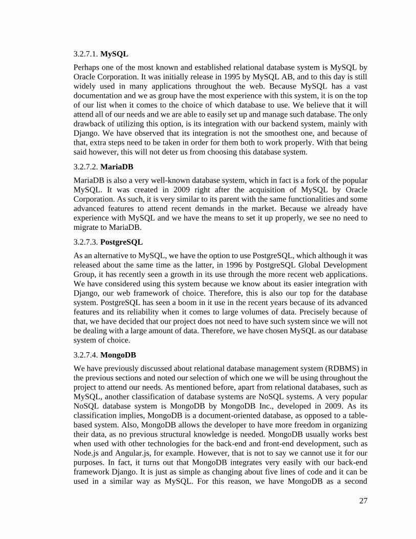
27
3.2.7.1. MySQL
Perhaps one of the most known and established relational database system is MySQL by
Oracle Corporation. It was initially release in 1995 by MySQL AB, and to this day is still
widely used in many applications throughout the web. Because MySQL has a vast
documentation and we as group have the most experience with this system, it is on the top
of our list when it comes to the choice of which database to use. We believe that it will
attend all of our needs and we are able to easily set up and manage such database. The only
drawback of utilizing this option, is its integration with our backend system, mainly with
Django. We have observed that its integration is not the smoothest one, and because of
that, extra steps need to be taken in order for them both to work properly. With that being
said however, this will not deter us from choosing this database system.
3.2.7.2. MariaDB
MariaDB is also a very well-known database system, which in fact is a fork of the popular
MySQL. It was created in 2009 right after the acquisition of MySQL by Oracle
Corporation. As such, it is very similar to its parent with the same functionalities and some
advanced features to attend recent demands in the market. Because we already have
experience with MySQL and we have the means to set it up properly, we see no need to
migrate to MariaDB.
3.2.7.3. PostgreSQL
As an alternative to MySQL, we have the option to use PostgreSQL, which although it was
released about the same time as the latter, in 1996 by PostgreSQL Global Development
Group, it has recently seen a growth in its use through the more recent web applications.
We have considered using this system because we know about its easier integration with
Django, our web framework of choice. Therefore, this is also our top for the database
system. PostgreSQL has seen a boom in it use in the recent years because of its advanced
features and its reliability when it comes to large volumes of data. Precisely because of
that, we have decided that our project does not need to have such system since we will not
be dealing with a large amount of data. Therefore, we have chosen MySQL as our database
system of choice.
3.2.7.4. MongoDB
We have previously discussed about relational database management system (RDBMS) in
the previous sections and noted our selection of which one we will be using throughout the
project to attend our needs. As mentioned before, apart from relational databases, such as
MySQL, another classification of database systems are NoSQL systems. A very popular
NoSQL database system is MongoDB by MongoDB Inc., developed in 2009. As its
classification implies, MongoDB is a document-oriented database, as opposed to a table-
based system. Also, MongoDB allows the developer to have more freedom in organizing
their data, as no previous structural knowledge is needed. MongoDB usually works best
when used with other technologies for the back-end and front-end development, such as
Node.js and Angular.js, for example. However, that is not to say we cannot use it for our
purposes. In fact, it turns out that MongoDB integrates very easily with our back-end
framework Django. It is just as simple as changing about five lines of code and it can be
used in a similar way as MySQL. For this reason, we have MongoDB as a second

28
alternative to our main database. Another advantage of possibly using MongoDB would be
that in doing so, we as developers do not need to host the database in our server. With
Mongo, we can offer a free service offered by them where they host the database for us. A
benefit of using this feature, would be an enhanced security for the data stored and also it
would decrease the load in our server.
3.2.7.5. DynamoDB
Another option available for NoSQL databases is DynamoDB created by Amazon, and the
database used in Amazon Web Services. As we have mentioned before, ideally this would
be our database of choice if we were to choose the Amazon ecosystem to host our server
and other functionalities for our project. However, consolidating all of our services under
this umbrella would only increase our cost, which is not attractive for us. Therefore, we
have decided not to go forward with this option.
3.2.7.6. Final Considerations and Selection
With our previous research and discussion shown in the previous sections, we have come
to two final candidates: MySQL and MongoDB. Both are great selections for our project
and would serve our users in a more than capable way. As shown, a drawback of using
MySQL is its not so smooth integration with Django as the versions do not work too well
together. However, that is a very small obstacle and we would classify it as more of a
nuisance than a problem. This becomes more prominent only when more than two
developers are working at the same project when using different host environments. If this
situation becomes the norm for our development environment, we then can consider the
migration for MongoDB. As observed before, this migration would be as simple as
changing a few lines of codes. Also, the load on our server would be reduced which could
improve the data handling for the various other features we will implement. With these
considerations in mind, we have opted to use MySQL for now. If any problems arise, we
will do the migration over to MongoDB.
We decided to go forward using MongoDB as out main database. The reasoning for this
was to facilitate the communication of the devices and the database as JSON objects can
help us achieve that. Also, with this option we were able to host the database in a third
party service reducing the load from our virtual machine and the raspberry pi.
Table 7 Comparison Between MySQL and MongoDB
Feature MySQL MongoDB
Easy Integration
Organization Tie Tie
Documentation
Support
Load Handling
3.2.8. Web Technologies
Web development is a big portion of our project as we intend to provide the user with a
web application where they will be able to manage and control their system. As such,
careful consideration was taken when deciding which web technologies would be
implemented and how they were going to be used to better serve the end-user. In the

29
following section we will compare some of the most popular programming languages and
frameworks used for web development.
3.2.8.1. PHP
A fundamental programming language used in web development is Hypertext Preprocessor
(PHP). It was released in 1995 and is still widely used to this day. As our web application
will have a strong connection to our database of choice, it is imperative to use a technology
that will allow us to manipulate such data. PHP would be essential for the functioning of
our project if we were to build a barebone web application, without the use of web
frameworks, as we have decided to do so, and will discuss in sections ahead. Nonetheless,
it is worth mentioning that PHP would be very important to allow us to implement our
project.
3.2.8.2. Python
Naturally, since PHP will not be the backend language for our application, we need an
alternative. Such alternative is Python. Python was first released in 1990 by Guido van
Rossum and is widely used today for a number of different applications. As a group, we
have a lot of experience in using Python for programming projects and because of that we
have all agreed it would be beneficial for us to utilize such language. Also, since we have
decided to use a web framework to aid in the development of our web application which
uses Python as their base language, it only further enforced our decision.
3.2.8.3. Django
Django is a web framework which allows rapid deployment of web applications that uses
Python as their base language. As we have discussed before, we have a lot of experience
in utilizing Python as a programming language. Also, because of time constraints and to
allow faster and uniform testing of our application we have decided to use such framework.
With our experience, we believe this will greatly benefit us to be able to implement the
different functionalities we have decided for this project. Also because of the many tools
available for Django and its seamless integration with the other technologies we are using
for our system it will make our development process occur more fluently.
3.2.8.4. Flask
Flask, similar to Django, is also a popular web framework. However, its main difference
is that is not as “well-packed” as Django. Meaning that to achieve what we can with
Django, many extra steps would need to be taken, and therefore the development process
would become cumbersome and more time consuming. Because Django allows us to test
many functionalities in a smaller time frame, we have decided not to choose Flask as our
web framework.
3.2.9. Front End Technologies
All web applications function on the basic mixture of Hypertext Markup Language
(HTML), Cascading Style Sheet (CSS), and JavaScript. In the following sections, we will
discuss how do we plan to integrate these technologies in our project and why they have
extreme in importance in helping us achieve our goals and how they will also work in

30
unison with the front-end framework of choice, which will be discussed in the section
following this one – Section 3.2.7.
3.2.9.1. Hypertext Markup Language
Hypertext Markup Language, or HTML, is a fundamental piece of a website. Everything
that is displayed to a user in a web application has its roots in a HTML element. Most often,
HTML is also accompanied by other technologies such as CSS, which allows the web
developer to control certain visual aspects of HTML elements and also JavaScript, which
allows the developer to integrate interactive elements to the web application.
3.2.9.2. Cascading Style Sheet
Cascading Style Sheet, or CSS, is another fundamental piece of a website. As we have
mentioned before, it goes hand in hand with HTML. With CSS files and functions, the
developer can directly control how the information is presented to the user. For example,
with the relevant functions, we can choose to display a text in bold format or not. We can
organize the text in different colors, with different backgrounds, different sizes and many
other options.
3.2.9.3. JavaScript
Another very important cornerstone of web technologies, is JavaScript. This scripting
language allows the developer to control the behavior of web applications. It is similar to
high level programming languages such as C and Java, and therefore we are able to
manipulate elements to fit our needs and create functions which will allow us to create an
interactive web application for the user and provide them an intuitive way to utilize our
product.
3.2.10. Front-End Frameworks
A very important aspect of our project is the user interface. We want our users to have a
easy to use interface that provides them with all the information they need with ease of
access and at the same time in a pleasant way. Therefore, it is important to utilize design
aspects that will allow that. In the next sections, we will discuss front-end frameworks that
will allow us to provide such experience for our users.
3.2.10.1. Bootstrap
One of the most commonly used front-end framework is Bootstrap. Created in 2010 by
Mark Otto and Jacob Thornton Bootstrap has seen a wide adoption by mane web designers
given it simplicity and its visual appeal. It is a framework that allows large customization
of a web page, ranging from alterations to the typography to how the contents are organized
within the viewport. Bootstrap works together with CSS and JavaScript to provide such
visual experience to the end user. Even though Bootstrap allows us, as the developer, to
customize our user interface in a lot of different ways, exactly because this is a framework
that has become so popular, we have decided we would use something different in order to
have a greater impact with the visual appearance of our project and to be somewhat
different from the most common visual style used in many popular websites nowadays.

31
3.2.10.2. Material Design Bootstrap
As we have previously discussed, we will not be using Bootstrap; however, we will be
using a very similar framework which is based on Bootstrap. That is Material Design
Bootstrap. We believe that Bootstrap provides great customization, and as mentioned, we
also believe that such customizations have become somewhat repetitive. Meanwhile, we
as a group, also find Google’s design initiative to be visually appealing. Because of that,
we decided to utilize a framework that combines both of the best worlds. Therefore, we
will be using as the framework for our visual interface, Material Design Bootstrap. With
this technology, we will be able to provide the users of our product with a beautiful
interface that is similar to what they are used to, and therefore allowing the usability to be
easy, and also with an appealing design so it is pleasant to use. It is worth noting that some
features of MDB are paid – as opposed to Bootstrap which is free. However, this is not
much of an obstacle, since we believe we can achieve sufficient usability of our product
with the free elements they offer.
3.2.10.3. Foundation
Another popular design framework is Foundation by ZURB. Foundation is also a recent
framework that has seen wide adoption across many websites. While we also find the
elements and customization provided by this framework also visually appealing, we also
believe that its documentation is lackluster. Because of that, we have decided not to adopt
such design.
3.2.10.4. Materialize CSS
A framework that is also worth mentioning is Materialize CSS, created by a group of
students from Carnegie Mellon University, Alvin Wang, Alan Chang, Alex Mark, and
Kevin Louie. Materialize CSS also offers customization of elements that is attractive to us,
and that is why we have considered this framework. We believe that we would be able to
build an easy to use and visually pleasing website with such framework. Because of this,
we have not eliminated this option as one of our final candidates, even though Material
Design Bootstrap is the framework that will most likely be used in the final product.
However, if MDB proves to not be sufficient to achieve our goals or the need of paid
elements becomes necessary, we will certainly switch to Materialize CSS, as it is free of
charge and can also provide us with the necessary customization.
In figures 4, 5, and 6 we can see a comparison between our top choices for the front-end
framework.
32
Figure 4. Example of Material Design for Bootstrap Component
Figure 5. Example of Materialize CSS Component
Figure 6. Example of Bootstrap Component
As we have mentioned before, we believe that the usage of Bootstrap as a front-end
framework has become so popular that is has lost its appeal. Because of that, we have
chosen to work with Material Design for Bootstrap that give us and our end user a
refreshing appearance with functionalities that are already known to them.
3.2.11. Infrared Sensing Technologies
Infrared sensors can be utilized to monitor temperature due to blackbody radiation. We
have chosen a passive infrared sensor (PIR) for detection of users and a near infrared sensor
(NIR) for fire detection. This section will be utilized to look at the advantages and

33
disadvantages to using this technology for our project as well as the challenges we will
need to overcome.
3.2.11.1. Passive Infrared (PIR) Sensing
A passive infrared sensor is a pyro-electric sensor which is sensitive to infrared radiation.
PIR sensors detect a change in infrared activity and will output either an ‘on’ or ‘off’ signal
corresponding to a 3V or 0V output. They are energy efficient due to the 5V input voltage
and an input current lower than 50mA, which makes this a good selection for our system
to be cost effective in terms of energy usage. The sensors themselves have a relatively
inexpensive unit cost which lowers the base expenses of our system.
The PIR sensor consists of two separate semiconductor materials with sensitivity to
infrared radiation. Each of these correspond to a certain area, and these areas are
consistently being refreshed and updated every blockade period which is on the scale of
seconds. [Home Automation with PIR] When someone walks in from of one portion of the
sensor there is a positive differential change in the level of infrared radiation, so the sensor
turns on. The opposite happens when someone leaves the sensor zone: a negative
differential in infrared radiation occurs and the sensor turns on. The working mechanisms
of the system are shown in figure 7.
Figure 7. Working Mechanisms of PIR sensor [1]
One challenge that the PIR sensors pose to our system is that they can detect human
presence accurately only when the person is in motion. The sensors are designed to only
see when there is a difference in infrared radiations which only occurs when someone is
walking into or out of the sensor area. Small changes may occur and trigger the sensor
when someone is moving within the sensor zone, but whenever someone is in the sensor
zone and still the sensor cannot detect them.

34
3.2.11.2. Near-Infrared (NIR) Sensing
Near-infrared sensing techniques have been utilized in many different experiments and
projects for temperature mapping and detection. The near- infrared portion of the
electromagnetic wave spectrum is between 0.7-1.1 microns. There are many devices which
can detect and map radiation in this range such as charge-coupled devices (CCDs) and
photodiodes. A CCD camera can both detect the radiation and map it in an array of pixels
which produces a full picture. We’ve chosen to use a photodiode in our experiment because
it is low cost and can still detect fire, and since we aren’t trying to actually map it in our
system it is a useful tool.
A NIR CCD camera could potentially be used to make our fire detection system more
reliable because it has many features which allow the camera to discern between noise
sources and an actual fire. One study used a CCD camera which operated in the UV, visible,
and NIR spectrums and it utilized the UV spectrum for detection on the OH and CH bands
at 314.3 and 390 nanometers.[3] It used the visible spectrum for the detection on CH bands
at 431.4 and 473.7 nanometers and C2 bands at 516.5 nanometers. Detections on these
bands are utilized for trigger verification. The main spectrum for this device was in the
NIR spectrum between 750 and 1100 nanometers.
3.2.11.3. Infrared Lenses
We’ve decided to put a lens in front of our NIR sensor to increase its range of detection.
There are several candidates for the composition of the lens and we noted the characteristics
of each including transmission wavelengths, reflectance, refractive index, and cost. We
will also analyze the type of lens and characteristics such as focal length which will be
ideal for our sensors.
N-BK7
This material has a refractive index between 1.5 and 1.52 in our emission spectrum which
will make the material transparent due to the small disparity between the indexes of the air
and the glass. Figure 0.0.1 shows the transmission spectrum of N-BK7 and we can observe
it is around 90% up to 2 microns. N-BK7 is relatively inexpensive and we can buy a lens
for our purposes for between twenty and fifty dollars. This is the most likely candidate for
our NIR sensors.

35
Figure 8. Transmission Spectrum of N-BK7
Source: https://bit.ly/2LyUzbq
Zinc Selenide
This material has a refractive index between 2.48 and 2.67 in our emission spectrum so
reflectance will be high due to the large disparity in the refractive indexes of air and the
glass. Figure 0.0.2 shows the transmission spectrum of Zinc Selenide and we can see that
transmission is much lower than N-BK7 at around 70% for our spectrum. Zinc Selenide is
a relatively expensive material so this glass will not be used for our sensors.
Figure 9. Transmission spectrum of Zinc Selenide
Source: https://bit.ly/2LyUWTm
Calcium Fluoride
This material has a refractive index of between 1.42 to 1.43 in our emission spectrum which
is great for our purposes because there is a small disparity between the indexes of air and
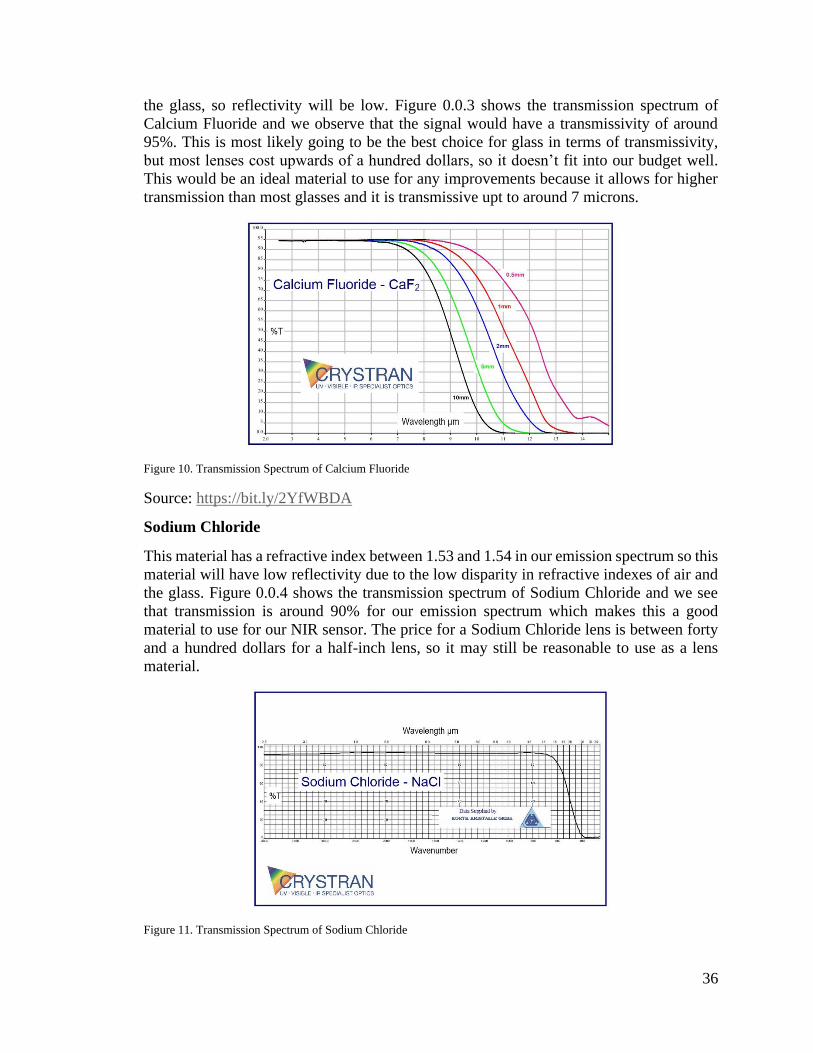
36
the glass, so reflectivity will be low. Figure 0.0.3 shows the transmission spectrum of
Calcium Fluoride and we observe that the signal would have a transmissivity of around
95%. This is most likely going to be the best choice for glass in terms of transmissivity,
but most lenses cost upwards of a hundred dollars, so it doesn’t fit into our budget well.
This would be an ideal material to use for any improvements because it allows for higher
transmission than most glasses and it is transmissive upt to around 7 microns.
Figure 10. Transmission Spectrum of Calcium Fluoride
Source: https://bit.ly/2YfWBDA
Sodium Chloride
This material has a refractive index between 1.53 and 1.54 in our emission spectrum so this
material will have low reflectivity due to the low disparity in refractive indexes of air and
the glass. Figure 0.0.4 shows the transmission spectrum of Sodium Chloride and we see
that transmission is around 90% for our emission spectrum which makes this a good
material to use for our NIR sensor. The price for a Sodium Chloride lens is between forty
and a hundred dollars for a half-inch lens, so it may still be reasonable to use as a lens
material.
Figure 11. Transmission Spectrum of Sodium Chloride
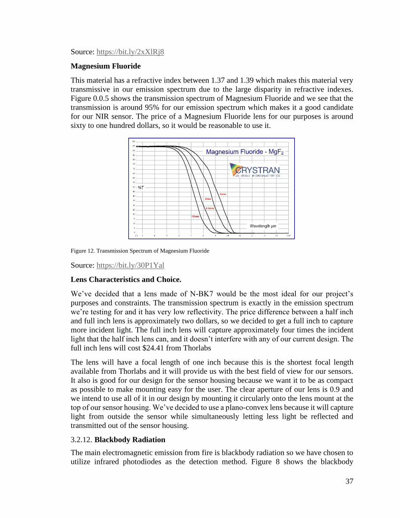
37
Source: https://bit.ly/2xXlRj8
Magnesium Fluoride
This material has a refractive index between 1.37 and 1.39 which makes this material very
transmissive in our emission spectrum due to the large disparity in refractive indexes.
Figure 0.0.5 shows the transmission spectrum of Magnesium Fluoride and we see that the
transmission is around 95% for our emission spectrum which makes it a good candidate
for our NIR sensor. The price of a Magnesium Fluoride lens for our purposes is around
sixty to one hundred dollars, so it would be reasonable to use it.
Figure 12. Transmission Spectrum of Magnesium Fluoride
Source: https://bit.ly/30P1Yal
Lens Characteristics and Choice.
We’ve decided that a lens made of N-BK7 would be the most ideal for our project’s
purposes and constraints. The transmission spectrum is exactly in the emission spectrum
we’re testing for and it has very low reflectivity. The price difference between a half inch
and full inch lens is approximately two dollars, so we decided to get a full inch to capture
more incident light. The full inch lens will capture approximately four times the incident
light that the half inch lens can, and it doesn’t interfere with any of our current design. The
full inch lens will cost $24.41 from Thorlabs
The lens will have a focal length of one inch because this is the shortest focal length
available from Thorlabs and it will provide us with the best field of view for our sensors.
It also is good for our design for the sensor housing because we want it to be as compact
as possible to make mounting easy for the user. The clear aperture of our lens is 0.9 and
we intend to use all of it in our design by mounting it circularly onto the lens mount at the
top of our sensor housing. We’ve decided to use a plano-convex lens because it will capture
light from outside the sensor while simultaneously letting less light be reflected and
transmitted out of the sensor housing.
3.2.12. Blackbody Radiation
The main electromagnetic emission from fire is blackbody radiation so we have chosen to
utilize infrared photodiodes as the detection method. Figure 8 shows the blackbody
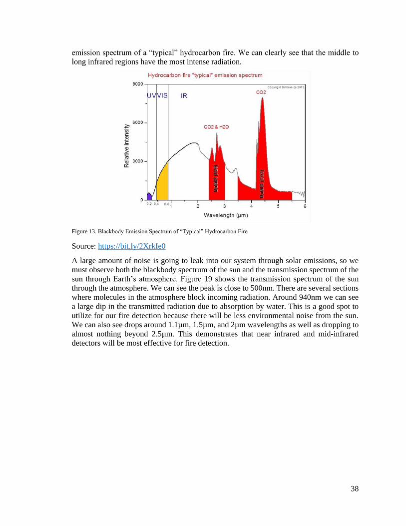
38
emission spectrum of a “typical” hydrocarbon fire. We can clearly see that the middle to
long infrared regions have the most intense radiation.
Figure 13. Blackbody Emission Spectrum of “Typical” Hydrocarbon Fire
Source: https://bit.ly/2XrkIe0
A large amount of noise is going to leak into our system through solar emissions, so we
must observe both the blackbody spectrum of the sun and the transmission spectrum of the
sun through Earth’s atmosphere. Figure 19 shows the transmission spectrum of the sun
through the atmosphere. We can see the peak is close to 500nm. There are several sections
where molecules in the atmosphere block incoming radiation. Around 940nm we can see
a large dip in the transmitted radiation due to absorption by water. This is a good spot to
utilize for our fire detection because there will be less environmental noise from the sun.
We can also see drops around 1.1µm, 1.5µm, and 2µm wavelengths as well as dropping to
almost nothing beyond 2.5µm. This demonstrates that near infrared and mid-infrared
detectors will be most effective for fire detection.

39
Figure 14. Transmission Spectrum of the Sun
Source: https://bit.ly/2XMKLAl
3.2.13. Raspberry Pi 3 Model B+
The Raspberry Pi 3 Model B+ is the final revision of the Raspberry Pi 3 range of single-
board computers. The Pi is an ARM-based system with a Broadcom BCM2837BO Cortex-
A53 (ARMv8) 64-bit SoC CPU. The specifications of the device are listed in tabular format
below. [11]
Table 8 Raspberry Specifications
Component Specifications
CPU Broadcom BCM2836B0 Cortex-A53 (ARMv8) 64-bit
SoC @ 1.4 Ghz
Memory 1GB LPDDR2 SDRAM
Wireless
Networking
2.4GHz and 5GHz IEE 802.11.b/g/n/ac wireless LAN,
Bluetooth 4.2, BLE
Wired Networking Gigabit Ethernet over USB2.0 (maximum throughput
300 Mbps)
Pin I/O Extended 40-pin GPIO header
USB 4 USB 2.0 Ports
Digital Video Full-size HDMI
Analog AV 4-pole stereo output and composite video port
Storage Micro SD port (loaded with 32GB SanDisk microSD
with Raspbian installed for the purposes of this project)
Power 5V/2.5A DC Power input
This is the model of pi that we have selected for use in our project, as it provides all the
necessary features required for the implementation of our system at a reasonable price. The

40
1.4 GHz ARM core should be adequate for the purposes of our project, as most of the
requisite computing tasks will be relatively light-weight. The same can be said of the
gigabyte of memory, especially considering the fact that there will be no need to run the
system with a graphical interface. The wireless networking support for Wi-Fi is robust and
meets our requirements on that front, as do the ethernet specs. The pin I/O will be used
where direct interface between the hub and a sensor or other component is useful or
necessary, and the micro SD port allows for a variety of storage cards of different sizes to
be installed. Although the Raspbian image installed to the card has a footprint of
approximately eight gigabytes, this still leaves the vast majority of the space on the 32-
Gigabyte SD card free, and this space will prove more than enough for the purposes of our
project.
3.2.14. Raspbian
Raspbian is a Debian-based operating system which is the officially-supported operating
system of the Raspberry Pi platform. Raspbian is optimized specifically for use with the
line of low-performance ARM CPUs that the Pi uses and is therefore a better choice than
making use of other, more generalized ARM operating systems which might otherwise be
compatible. Its status as a ‘default’ operating system for the Raspberry Pi also means that
information and documentation is highly available. Because the Raspberry Pi model that
has been purchased does not come with a pre-installed version of Raspbian, it has been
installed manually onto an SD card, which is then installed in the Pi itself.
The latest version of the Raspbian operating system is available from the Raspberry Pi
Foundation’s official website [10] and was downloaded and written to an SD card using
the dd utility with the command:
dd bs=1M if=2019-07-10raspbian-buster-full.img of=/dev/sdb
From there, the micro SD card was inserted into the Pi, which booted Raspbian without
issue.
3.2.15. Project Management Tools
As a group, we are working with many different files, ideas, coding snippets, and different
sources. As we all have different availability throughout the day, it is important for us to
always be able to communicate to other members of the group in an efficient manner. In
the following sections, we will discuss the tools we have utilized to do so.
3.2.15.1. Source Control
As a group, we are working with many different files, ideas, coding snippets, and different
sources. As we all have different availability throughout the day, it is important for us to
always be able to communicate to other members of the group in an efficient manner. In
the following sections, we will discuss the tools we have utilized to do so.
One option under consideration for source control is Git. Not only is Git a highly flexible
and mature system for source control and version management, but also boasts a selection
of sites which offer repository-hosting free of charge. Git would allow our group to both
collaborate asynchronously on the project, assisting in version and branch control, and
would also help to ensure that there is little to no chance of catastrophic data-loss as a result

41
of a hard-drive failure or accidental deletion, as the project data would be stored not only
on the machines of group-members, but also backed-up by the chosen hosting provider.
Git also offers convenience in the form of branches, which would allow group members to
experiment with bonus or wishlist features without affecting core development, and then
merge said features back into the core branch of the project if they happen to bear fruit. Git
tools are also ubiquitous, either as stand-alone programs, built into various IDEs either by
default or as community plug-ins, can be used from both command-line and through
graphical interfaces, and are available on practically every platform from Windows to Mac
to Linux.
3.2.15.2. Microsoft Office Suite
A big portion of this project is also the creation of the documentation for it. Because we
are all contributing to the same document, it is also important that each of us is able to do
so without interrupting the work of someone else. We therefore, took advantage of the
functionalities of Office 365, provided to us by the University of Central Florida in
partnership with Microsoft. Namely, in order to create such document, we used Microsoft
OneDrive, to store it, and Word, to edit it.
4. Related Standards and Design Constraints
4.1. Related Standards
4.1.1. IEEE 802.11 Wi-Fi
Wi-Fi provides a robust means for carrying out digital communications over a local area
network and is supported by a wide range of devices and can be integrated into devices
which do not directly support it via the use of pre-programmed standalone modules. Wifi
will be used as a means of achieving wireless communication between the devices used in
the project, and as a means of connecting the central hub to the internet via a Local Area
Network.
4.1.2. Universal Serial Bus
The Universal Serial Bus (USB) technology is a standard for facilitating hardware
communication between computers, peripheral devices, and other computers. It is another
standard that is practically ubiquitous in its implementation in consumer devices and is
therefore a key choice when it comes to methods for extending the functionality of devices
which are being controlled by the system or that of the central hub itself.
4.1.3. HTTP
Hypertext Transfer Protocol is a standard allowing for the transference of media over the
World Wide Web. HTTP is instrumental to our project plan as we have chosen to
implement out user interface as a web-based scheme in order to take advantage of the fact
that most consumer electronic devices have access to a web browser which can display and
interact with said content, saving the effort of having to design device-specific clients and
interfaces. Methods which allow the client to send information to the server such as the
HTTP POST method will be instrumental for tasks such as the authentication of users.

42
Additionally, it is worth mentioning that REST webservices most commonly makes use of
HTTP for data transmission, including the HTTP methods such as GET, POST, etc when
it comes to defining operations carried out through a webservice API. This is another way
in which HTTP is an important standard when it comes to the operation of our project, as
we have chosen to implement REST-Based webservices in order to create an API which
will improve the ease of communication between the server and other components of the
smart home system.
4.1.4. Hypertext Markup Language
The Hypertext Markup Language is a standard which defines the structure and layout of
documents and media designed to be transmitted over the Internet via the Hypertext
Transfer Protocol. HTML serves as the backbone for the web pages which will serve as the
primary means of interfacing with the server, and can be supported by other standards and
technologies such as CSS, JavaScript, Angular.js, etc. Which provide a more responsive or
visually impressive front-end experience.
4.1.5. Cascading Style Sheet
CSS is a standard for managing the look and feel of webpages across the entirety of a site
and is commonly used in tandem with HTML for web page design. The ability to create a
single CSS sheet which can be re-used to define the visual properties of an entire set of
webpages is useful for ensuring visual consistency across the webpages produced for this
project and as a means of reducing workload, and the fact that CSS support is ubiquitous
ensures that its application to the project requires essentially no extra effort.
4.1.6. Coding Standards
As we have mentioned in previous sections and it will be shown in more detail in following
sections, the software portion of this project will be mainly written utilizing the Python
programming language. As such, it is necessary for us, as developers, to follow a coding
convention, styling, and standard, namely PEP 8. An example is shown in figure x. These
guidelines will also serve as a tool to streamline the process of writing many different
sections of the code with different people working on it. Also, the main purpose of
following these guidelines is to improve the readability of our code, not only for our own
benefit, which will help us write better and code and debug it easily, but for the benefit of
a third party in case it comes the time were the code will be shared.
Figure 15. Example of PEP 8 Guideline
Our back-end framework Django also follows PEP 8 as it is written in Python. Django also
has its own coding style which we will be following closely to keep the uniformity and
again improve our code readability. In figures x and x, a comparison between a correct and
a wrong coding style is shown.
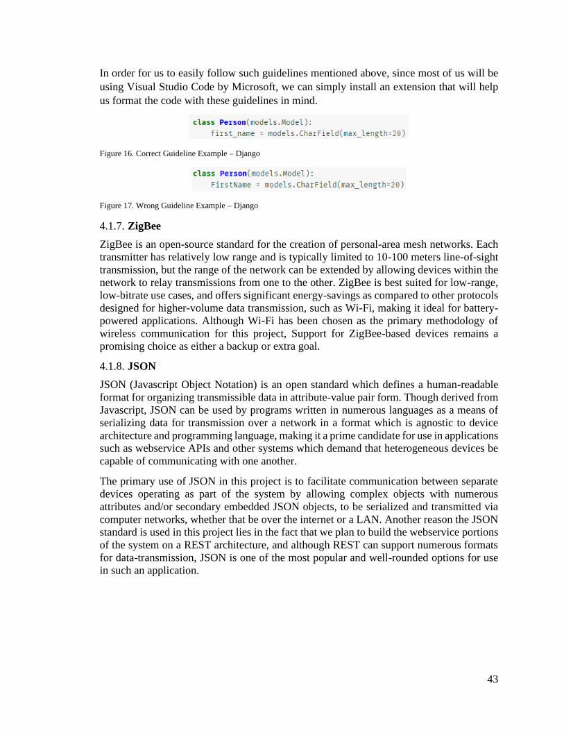
43
In order for us to easily follow such guidelines mentioned above, since most of us will be
using Visual Studio Code by Microsoft, we can simply install an extension that will help
us format the code with these guidelines in mind.
Figure 16. Correct Guideline Example – Django
Figure 17. Wrong Guideline Example – Django
4.1.7. ZigBee
ZigBee is an open-source standard for the creation of personal-area mesh networks. Each
transmitter has relatively low range and is typically limited to 10-100 meters line-of-sight
transmission, but the range of the network can be extended by allowing devices within the
network to relay transmissions from one to the other. ZigBee is best suited for low-range,
low-bitrate use cases, and offers significant energy-savings as compared to other protocols
designed for higher-volume data transmission, such as Wi-Fi, making it ideal for battery-
powered applications. Although Wi-Fi has been chosen as the primary methodology of
wireless communication for this project, Support for ZigBee-based devices remains a
promising choice as either a backup or extra goal.
4.1.8. JSON
JSON (Javascript Object Notation) is an open standard which defines a human-readable
format for organizing transmissible data in attribute-value pair form. Though derived from
Javascript, JSON can be used by programs written in numerous languages as a means of
serializing data for transmission over a network in a format which is agnostic to device
architecture and programming language, making it a prime candidate for use in applications
such as webservice APIs and other systems which demand that heterogeneous devices be
capable of communicating with one another.
The primary use of JSON in this project is to facilitate communication between separate
devices operating as part of the system by allowing complex objects with numerous
attributes and/or secondary embedded JSON objects, to be serialized and transmitted via
computer networks, whether that be over the internet or a LAN. Another reason the JSON
standard is used in this project lies in the fact that we plan to build the webservice portions
of the system on a REST architecture, and although REST can support numerous formats
for data-transmission, JSON is one of the most popular and well-rounded options for use
in such an application.
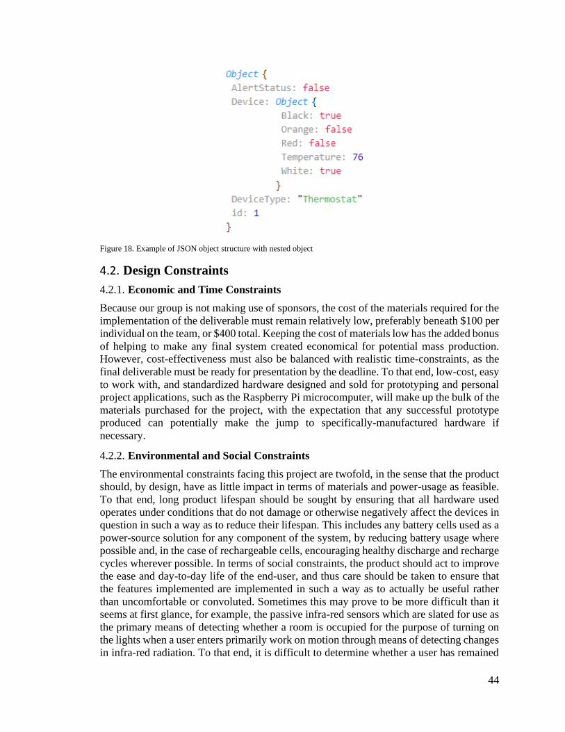
44
Figure 18. Example of JSON object structure with nested object
4.2. Design Constraints
4.2.1. Economic and Time Constraints
Because our group is not making use of sponsors, the cost of the materials required for the
implementation of the deliverable must remain relatively low, preferably beneath $100 per
individual on the team, or $400 total. Keeping the cost of materials low has the added bonus
of helping to make any final system created economical for potential mass production.
However, cost-effectiveness must also be balanced with realistic time-constraints, as the
final deliverable must be ready for presentation by the deadline. To that end, low-cost, easy
to work with, and standardized hardware designed and sold for prototyping and personal
project applications, such as the Raspberry Pi microcomputer, will make up the bulk of the
materials purchased for the project, with the expectation that any successful prototype
produced can potentially make the jump to specifically-manufactured hardware if
necessary.
4.2.2. Environmental and Social Constraints
The environmental constraints facing this project are twofold, in the sense that the product
should, by design, have as little impact in terms of materials and power-usage as feasible.
To that end, long product lifespan should be sought by ensuring that all hardware used
operates under conditions that do not damage or otherwise negatively affect the devices in
question in such a way as to reduce their lifespan. This includes any battery cells used as a
power-source solution for any component of the system, by reducing battery usage where
possible and, in the case of rechargeable cells, encouraging healthy discharge and recharge
cycles wherever possible. In terms of social constraints, the product should act to improve
the ease and day-to-day life of the end-user, and thus care should be taken to ensure that
the features implemented are implemented in such a way as to actually be useful rather
than uncomfortable or convoluted. Sometimes this may prove to be more difficult than it
seems at first glance, for example, the passive infra-red sensors which are slated for use as
the primary means of detecting whether a room is occupied for the purpose of turning on
the lights when a user enters primarily work on motion through means of detecting changes
in infra-red radiation. To that end, it is difficult to determine whether a user has remained

45
in a room after entering and remaining still for a long period of time, i.e. while watching
television, and creative solutions will be required to ensure that the system does not become
confused and act against the interests of the user due to a lapse in detection.
4.2.3. Health and Safety Constraints
Due to the low voltages and low-power wireless transmission involved in the
implementation of the smart home system, there are few key health and safety concerns
related directly to the operation of the system itself. However, there is potential for key
misunderstandings between what the product has been designed to do and what the user
expects it to be capable of which might result in safety concerns. For example, a core
feature of our product is for it to act as a supplementary fire-detection system via the use
of near-infra-red (NIR) sensors tuned to detect open flames. Though the purpose of this
system is to improve safety by alerting the user to a potential fire in high-risk areas of the
household, there is potential for danger if the user does not understand that the system is
not designed to be a replacement for a standardized fire alarm and smoke-detection system.
It is important that the user is informed clearly and is aware at all times that this aspect of
the system is meant to be a supplement to existing fire-detection and prevention
technology, and that it cannot of its own accord notify emergency personnel and should
not be used as a replacement for a code-compliant fire alarm system.
4.2.4. Manufacturability Constraints
By and large, the largest concerns when it comes to manufacturability constraints include
the ease of manufacture in terms of processes and automation, and the cost of
manufacturing the system. There are many electronic components of the system which are,
by and large, already mass-produced in and of themselves, and as such the physical
manufacturability of such components is outside the scope of our group’s concern. Where
manufacturability is a concern is in such components that are produced either through
custom modification of existing devices or through original design, potential examples
being infra-red sensors using special lenses to improve the performance of the sensors in
question, or electronic locking devices which have been modified to allow for the use of
nonstandard networking hardware in order to connect them with the smart-home system.
In such cases, care must be taken to ensure that the modifications made are clearly
documented, simple enough to roll into a manufacturing process if necessary, and that any
components of the system which are implemented in the prototype by modifying a
commercial product can be produced ‘from scratch’ in a potential final product so as to
avoid intellectual property infringement.
The other primary concern when it comes to manufacturability is the cost of the materials
and processes involved. Similar to the economic constraints section, lower cost improves
the viability of manufacturing the system and should be sought out wherever it does not
compromise the core design goals of the project. To that end, components should be
selected for viability in price and long-term manufacturability, along with immediate
availability (I.E, avoiding technologies which have been introduced so recently as to be
difficult to acquire at a reasonable price, such as Bluetooth 5.1).
46
4.2.5. Political Constraints
As a service with a web-based component, the system will be required to comply with the
laws of any jurisdiction in which it is deployed. In order to keep the scope of the project
reasonable, compliance will mostly be sought with existent United States Because we do
not expect to be receiving or working with financial information, the legal requirements in
that sphere can be more or less eliminated. All the same, in the event that such a product
as ours does go into production, care will have to be taken to ensure that compliance is met
with any other internet data regulations as exist in the United States governing information
privacy, I.E, as regulations such as CalOPPA exist which suggest that a privacy policy at
the very least should be included in any website that collects personally identifiable
information. All the same, since the goal is to collect and keep as little personally
identifiable information as is necessary to allow the design goals of the project to be met,
it is doubtful that significant issues regarding political constraints will be met.
4.2.6. Ethical Constraints
The primary ethical constraints implicit in this project relate to the data and information
which might be collected by a system entwined with the user’s home. To that end,
developers and operators of the system have a responsibility to the end-user to collect as
little personally identifiable information as possible, and to ensure that any information
which is collected cannot be easily accessed without proper motive. Because the smart
home system will require that devices be integrated with the user’s home networks, it is
also imperative from an ethical point of view that the system not be easily compromised
by unlawful third parties. Poor security is one of the largest issues facing IoT applications
in the modern day, and avoiding such pitfalls, both in the user’s home and in the Internet-
based support systems to which it connects is imperative. Likewise, contingencies designed
to lessen the exposure of personally identifiable information in the event of a breach, such
as hash-and-salt password management schemes, should also be implemented in addition
to proper security. By taking these concerns into account and constructing our system
accordingly, we should be able to provide a system which the end-user can make use of
without worrying about potential pitfalls when it comes to security or safety, and perhaps
even more importantly, we will have created a system which will not act to compromise
those aspects of privacy and security.
4.2.7. Software Prototyping Constraints
Software prototyping in terms of this project’s scope will mostly follow a rapid-prototyping
paradigm, with programs designed for testing and exploring the means and idiosyncrasies
in communication between various components of the system, i.e. between a central hub
device and sensors and devices placed throughout the home, or between the central hub
and the webserver, but which are not necessarily included in the final product. To that end,
prototypes should largely be used as a proof of concept for core design features and as a
means by which interconnectivity can be confirmed and tested. Examples might be a
program to act as an example of how the central hub will connect to, carry out
authentication with, and receive commands from the webserver. Another example might
be a program whose feature set consists solely of being able to turn a light on and off via
communication with the central hub. Prototyping should thus be constrained to simple and
‘quick’ tasks, in order to leave as much time as possible to create, polish, and otherwise
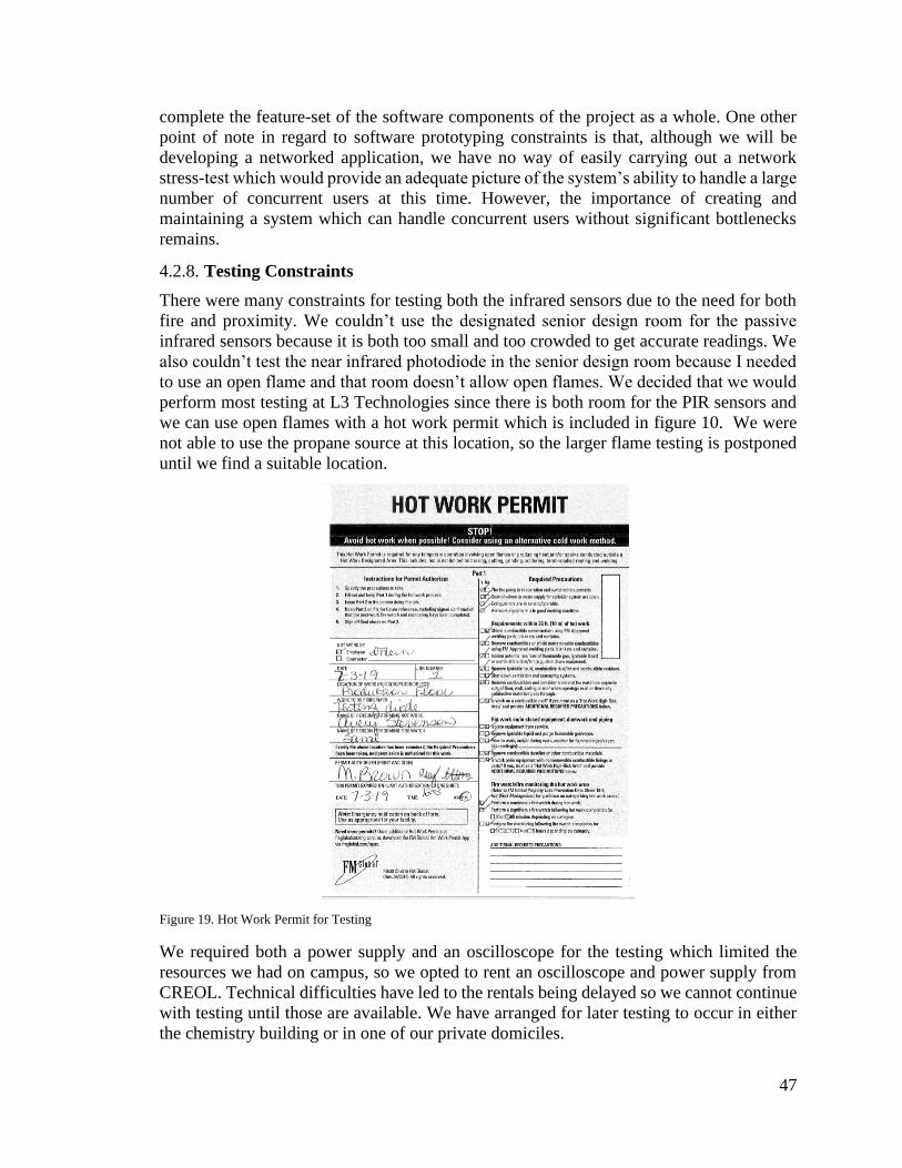
47
complete the feature-set of the software components of the project as a whole. One other
point of note in regard to software prototyping constraints is that, although we will be
developing a networked application, we have no way of easily carrying out a network
stress-test which would provide an adequate picture of the system’s ability to handle a large
number of concurrent users at this time. However, the importance of creating and
maintaining a system which can handle concurrent users without significant bottlenecks
remains.
4.2.8. Testing Constraints
There were many constraints for testing both the infrared sensors due to the need for both
fire and proximity. We couldn’t use the designated senior design room for the passive
infrared sensors because it is both too small and too crowded to get accurate readings. We
also couldn’t test the near infrared photodiode in the senior design room because I needed
to use an open flame and that room doesn’t allow open flames. We decided that we would
perform most testing at L3 Technologies since there is both room for the PIR sensors and
we can use open flames with a hot work permit which is included in figure 10. We were
not able to use the propane source at this location, so the larger flame testing is postponed
until we find a suitable location.
Figure 19. Hot Work Permit for Testing
We required both a power supply and an oscilloscope for the testing which limited the
resources we had on campus, so we opted to rent an oscilloscope and power supply from
CREOL. Technical difficulties have led to the rentals being delayed so we cannot continue
with testing until those are available. We have arranged for later testing to occur in either
the chemistry building or in one of our private domiciles.

48
The fire detection sensor design includes a half inch lens which is mounted onto an
aluminum box containing the NIR photodiode. Both the lens and assembly weren’t
currently available due to both design time and shipping for the initial testing. We realized
that it’s difficult to keep the diodes pointed in the same direction during testing so further
testing will take this into account.
5. Project Hardware and Software Design Details
5.1. Hardware Design Details
5.1.1. AC Thermostat Design
For the AC Thermostat Unit, we will have to meet these Requirements:
• Turn ON/OFF AC Fan, Compressor, Heater, and Pump if applicable
• Produce working outputs of 24Vac
• Accurately read ambient room temperature
• Use a display and have some button controls
• Have a profile smaller than 8”x6”x1”
• Support 18 AWG wires
• Have a Minimum working range of 30m
The components ultimately chosen for this unit meet or exceed these requirements. We
ended up using a set of 3V relay that can handle up 10A at up to 220Vac. The components
will be small enough to fit in a PCB that will be placed inside a rectangular case that will
have a slot for a 1.5” square OLED display. The CTB0158-2 terminals will support up to
12 AWG wires so 18 AWG is no problem. The ESP8266 has a working range of 300m
Line Of Sight, so we should have no problem meeting the 30m range inside the home, this
will have to be tested. We will be using a DHT21 Temperature and humidity sensor that
has an accurate measurement with only a 2-5% deviation from actual room temp.
This design is considering a standard home AC system that is wired to use ~24Vac. The
relay system controlling the Fan, Compressor, Heater, and Heat Pump (if applicable) will
run on this 24Vac while the microcontroller, temperature sensor, and LCD screen require
3.3Vdc. To power the DC components, we will use a bridge rectifier composed of 4 1n4007
diodes to be stepdown by the lm2596 circuit to 3.3V. This system shall remain Isolated
from the 24Vac at the terminals. The typical AC system requires 5 terminals, Heat,
Compressor, Fan, Pump, RedC (power) for Cooling System, RedH (power) for the heating
system, and a Common terminal, see the next chart for a description of the functionality of
these wires. The common terminal will ensure that the thermostat is provided with an
uninterrupted power source.

49
Table 9 Terminals Descriptions
Color Terminal
Code
Purpose Description
Red R 24 VAC
Power
This is the 24V power terminal.
Most of the low-voltage
thermostats work with this voltage
although you can find them all the
way up to 50V.
It is not uncommon to find 2 red
cables Rh and Rc powering the
cooling and heating systems
separately
Black C 24 VAC
Common
This is the common ground for the
24V
White W Heat This is the terminal that energizes
the heater
Yellow Y Compressor This is the terminal that energizes
the compressor
Orange O Rv On in Cool O and B terminals interact with the
reverse valve. The reverse valve
controls the flow of refrigerant in
the piping system, basically
allowing for either cool or hot air.
Blue B Rv On in Heat Same as the terminal O but to call
for heat. It is common for the two
terminals to be combined. The
industry standard is when O/B is
ON the system cools, and vice
versa
Green G Indoor Fan Controls the Fan if the system
allows it.
Connecting the Power terminal to Heat, and Power to Fan will turn on the heater.
Connecting the Power to Compressor, and Fan will start the Cool Air. Knowing this we
can install have a line providing Vac power to the common terminal of the relays, the other
terminals will be connected to one of the poles. We will only consider common AC wiring
standards for the design; we will not be able to accommodate all systems with this unit.
To start with the design, the device will be using power directly from the Red terminal.
Our DC components will all function with a VCC of 3.3V so to use the 24Vac line we will
pass the voltage through a bridge rectifier and then to the LM2596 circuit that will provide
a steady voltage of 3.3V. This voltage will power the ESP-12F, the Temperature and

50
Humidity Sensor, the OLED Display, the relay board, and the Dual 4-Channel Multiplexer.
Since almost all our sensors and controlled components operate using either UART, SPI,
or I2C, and since the ESP-12F has only one communications array, we will not be able to
read or write data simultaneously to all those components. In our case, the MCU has only
9 useable GPIO pins. 4 GPIO pins are input only, one is analog in, therefore we have 4 for
our output applications. The four input pins will include 3 settings buttons and 1 data pin
from the DHT21. Two output GPIO will control the Cooling system/Heating System, and
the last two will be for software I2C display.
The following table is our Bill of Manufacturing for the thermostat. The BOM represents
most the components we will require to build this prototype. These costs are well below
our target Price of $50 despite many of the materials purchased here being bought at retail
price. We are not getting the discount we would get when buying in bulk straight from the
manufacturer. When we go in production the cost of injection molding our own exterior
would be a minute fraction of that of the $5 it will cost to prototype. We don’t expect
production costs to be greater than $15. This should provide a very good profit margin for
our product at $50 retail, while still undercutting most of the competition, making this
device our most profitable feature.
Table 10 Bill of Materials
Name Designator Footprint Quantity Manufacturer Part Manufacturer Price
LM2596 U1 LM2596 1 LM2596M LC Tech $ 1.60
DHT21 U2 DHT21 1 AM2301 SMT $ 2.50
PC817 U3 DIP-4 4 PC817 EVERLIGHT $ 0.10
SRA-12VDC-
CL
K1 SRA-
12VDC-
CL
4 SRA-12VDC-
CL
SONGLE $ 0.50
10k Resistor R1, R2,
R3, R4, R5
AXIAL-
0.3
5 Generic Generic $ 0.01
2k Resistor R6 AXIAL-
0.3
6 Generic Generic $ 0.01
ESP-12F U4 ESP-
12F
1 ESP-12F Expressiff $ 1.22
7.5in x 4in PCB PCB PCB 1 SD2019G14AC Advance Circuits $ 10
220 Resistor R7 AXIAL 4 Generic Generic $ 0.01
SMD
470h Inductor
H1 SMD 1 470h SMTelectronics $ 0.10
25V
100uf Capacitor
C1, C2 SOT 2 Generic Generic $ 0.05
Push
Button Switch
U4, U5 DIP-4 2 PBS12 EVERLIGHT $ 0.02
Total $16.12

51
Figure 20. Smart Thermostat Schematic
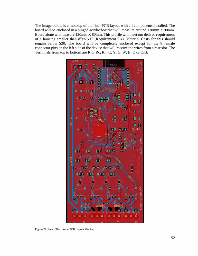
52
The image below is a mockup of the final PCB layout with all components installed. The
board will be enclosed in a hinged acrylic box that will measure around 130mm X 90mm.
Board alone will measure 120mm X 80mm. This profile will meet our desired requirement
of a housing smaller than 8”x6”x1” (Requirement 3.4). Material Costs for this should
remain below $20. The board will be completely enclosed except for the 8 female
connector pins on the left side of the device that will receive the wires from a rear slot. The
Terminals from top to bottom are R or Rc, Rh, C, Y, G, W, B, O or O/B.
Figure 21. Smart Thermostat PCB Layout Mockup

53
5.1.2. SMART Outlet Design
For the SMART Outlet Design we will need to meet the following requirements:
• Ability to open and close and Outlet Circuit
• Support a maximum draw of 15A
• Fit inside an NEC Standard Electrical Box Housing
• Use 12 AWG wire for AC Circuits
• Have a working range of 30M
With the components we’ve picked out we believe we will meet or exceed these
requirements. We will be using a 12V relay that can handle up 20A at up to 220Vac. The
HLK-PM12 PSU will be able to provide ample power to our DC components. The
components will be small enough to fit in a PCB that will be placed behind the outlet. The
CTB0158-2 terminals will support up to 12 AWG wires. Lastly the ESP8266 has a working
range of 300m Line of Sight, so we should have no problem meeting the 30m range inside
the home, this will have to be tested. These components will be similar to the once used in
the AC thermostat but at a smaller scale. For this unit we will only require One Relay that
can support up to 220Vac at a maximum current draw of 20A. One terminal will receive
the Hot input from the housing and power the circuit. A switching AC-DC power supply
will ensure the circuit receives a steady 12Vcc supply. The LM2596 will step that voltage
down to 3.3V for the embedded components. We used the same ESP8266 as all other
wireless components. This microcontroller will use one GPIO pin to control the relay and
we ultimately had to scrap the use of the current sensor.
This design will be very similar to the Smart Switch, we start with the Line In (Hot Wire)
connected to the PSU and the return to the Neutral Wire. The PSU will provide a constant
+12VCC that will power the Relay. We will need Isolate the Relay’s trigger signal from
the MCU. the LM2596 Step Down converter module will lower the +12VCC to +3.3V.
This signal voltage will be stemmed by an optocoupler (PC817) that the MCU can trigger
while remaining electrically isolated from the circuit with higher voltage. Since the ESP01s
has a HIGH signal of 3.3V there needs to be a power limiting resistor at the optocoupler
input since the max input voltage of the PC817 1.3V. The Line In will be connected to the
relay common terminal. The current sensor will measure the draw at the return line, so it
will only measure current when the device is consuming power, this will not measure the
current used by the system. The normally opened terminal will not be connected to
anything. The system will operate normally closed so that the outlet will still function even
if there is logic or system power failure. Having the 20A relay will ensure that if there is a
current surge the outlet’s breaker will trigger and the system will be protected. The logic
will be simple, toggling the relay breaks or closes the circuit. For our first prototype both
receptacles will dependent on one relay. In the future we may add another to control each
receptacle individually.

54
Figure 22. Smart Outlet Schematic

55
The following table is our Bill of Manufacturing for the outlet. The BOM represents all the
components we will require to build this prototype. These costs are well below our target
Price of $20 even though many of the materials being purchased here are bought at retail
price. We are not getting the discount we would get if we were ordering parts in bulk.
Notice that nearly 50% of the cost to prototype is the housing and receptacle. When we go
in production the cost of injection molding our own exterior would be a minute fraction of
that, coupled with a bulk price on a standard receptacle, our manufacturing costs should be
less than $9. This should allow us a sizeable profit margin of at least 50% and meet our
$20 retail target.
Table 11 Bill of Manufacturing
Name Designator Footprint Quantity Manufacturer Part Manufacturer Price
LM2596 U1 LM2596 1 LM2596M LC Tech $ 1.60
HLK-PM12 U2 PWRM-
TH_HLK-
PM12
1 HLK-PM12 HI-LINK $ 2.50
PC817 U3 DIP-4 1 PC817 EVERLIGHT $ 0.10
SRA-12VDC-
CL
K1 SRA-
12VDC-
CL
1 SRA-12VDC-
CL
SONGLE $ 0.25
10k Resistor R1, R2,
R3, R4,
R5
AXIAL-
0.3
5 Generic Generic $ 0.01
2k Resistor R6 AXIAL-
0.3
1 Generic Generic $ 0.01
ESP-12F U4 ESP-12F 1 ESP-12F Expressiff $ 1.22
2in x 3in PCB PCB PCB 1 SD2019G14O Advance Circuits $ 10
220 Resistor R7 AXIAL-
0.3
1 Generic Generic $ 0.01
SMD
470h Inductor
H1 SMD 1 470h SMT
electronics
$ 0.10
25V
100uf Capacitor
C1, C2 SOT 2 Generic Generic $ 0.05
Push
Button Switch
U4, U5 DIP-4 2 PBS12 EVERLIGHT 0.02
Total $15.77
You’ll find the PCB layout of the outlet in the next figure. All components will be laid out
in a 120mm X 40mm board. This will fit snuggly inside the mounting box right behind the
switch. There will be three labeled terminals behind the box for the Hot, Neutral, and

56
Ground wires. The mockup also illustrates the layout of the tracks and connections that
will be needed for the circuit. Not counted in the BOM but necessary during assembly will
be the series of solder tracks and jumper wires that will make up these connections. When
assembled, the device will be one compact unit with a 2” width, 4.9” height, and 3” depth.
Figure 23. Smart Outlet PCB Layout Mockup

57
5.1.3. Light Switch Design
For the Light Switch Controller, we will have to meet these requirements:
• Open/Close the circuit and turn ON/OFF whatever Light Fixture or appliance is
wired
• Allow for the switch to remain operational regardless of Relay position.
• Support a maximum load of 15 amps at 110-220Vac
• Fit in an NEC Standard Electrical Box Fixture
• Support 12 AWG wires
• Have a Minimum working range of 30m
The same components as the Outlet Unit should meet our requirements for the light switch.
We will be using the same 12V relay that can handle up 20A at up to 220Vac. The HLK-
PM12 PSU will be able to provide the power to our DC components. The components will
be small enough to fit in a PCB that will be placed besides the actual switch inside of a
custom housing. The CTB0158-2 terminals will support up to 12 AWG wires. Lastly the
ESP8266 has a working range of 300m Line of Sight, as stated previously this will have to
be verified during testing. There is one caveat with this unit and that is, unlike the Outlet,
we cannot take full control of the system. The user must be able to manually flip the switch
to turn the system on and off. This must also not create an open circuit within the system
that will turn off the MCU. To achieve this deliverable then we must use a 3-way switch
and a 3-way circuit between the switch and the controller.
Our design begins with the Line In (Hot Wire) connected to the PSU and the return to the
Neutral Wire. The PSU will provide a constant +12VCC that will power Relay. Our MCU
cannot provide 12 volts, it can’t even tolerate it, so we will need to provide isolation from
the Relay’s trigger signal, the LM2596 Step Down converter module will lower the
+12VCC to +3.3V. This signal voltage will be stemmed by an optocoupler (PC817) that
the MCU can trigger while remaining electrically isolated from the circuit with higher
voltage. Since the ESP01s has a HIGH signal of 3.3V there needs to be a power limiting
resistor at the optocoupler input since the max voltage the PC817 can withstand is 1.3V at
the input. The Line In will be connected to the relay common terminal. The current sensor
will measure the draw going into the terminal. The NC and NO terminals will be wired
with travelers to the SPDT Paddle Switch. The ground wire from the switch will connect
to the ground terminal of the board. We can describe the system’s logic using this table:
Table 12 Switch System State Machine
Relay State Switch State Light Bulb
Closed On On
Open On Off
Closed Off Off
Open Off On
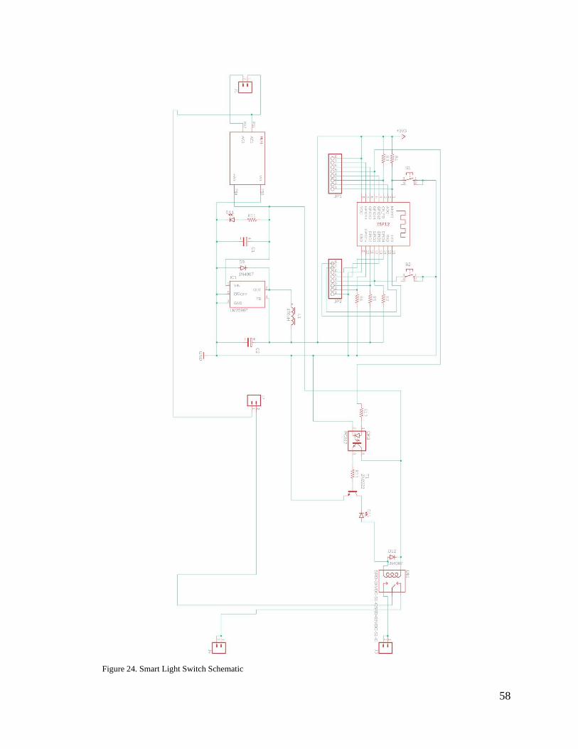
58
Figure 24. Smart Light Switch Schematic

59
Below, you will find our Bill of Manufacturing. These costs may be over our target Price
of $15 but keep in mind that many of the materials being purchased here are bought at retail
price. We are not getting the discount we would get if we were ordering parts in bulk.
Notice that nearly 60% of the cost to prototype is the housing and switch. When we go in
production the cost of injection molding our own exterior would be a minute fraction of
that, coupled with a bulk price on a standard paddle switch, our manufacturing costs should
be less than $9. This should allow us a sizeable profit margin and meet our $15 retail target.
Table 13 Bill of Manufacturing
Name Designat
or
Footpri
nt
Quantit
y
Manufacturer P
art
Manufacturer Price
LM2596 U1 LM2596 1 LM2596M LC Tech $
1.60
HLK-PM12 U2 PWRM-
TH_HLK-
PM12
1 HLK-PM12 HI-LINK $
2.50
PC817 U3 DIP-4 1 PC817 EVERLIGHT $
0.10
SRA-12VDC-
CL K1 SRA-
12VDC-
CL
1 SRA-12VDC-CL SONGLE $
0.25
10k Resistor R1, R2,
R3, R4,
R5
AXIAL-
0.3
5 Generic Generic $ 0.01
2k Resistor R6 AXIAL-
0.3
1 Generic Generic $ 0.01
ESP-12F U4 ESP-12F 1 ESP-12F Expressiff $
1.22
2in x 3in PCB PCB PCB 1 SD2019G14S Advance Circu
its
$ 10
220 Resistor R7 AXIAL-
0.3
1 Generic Generic $ 0.01
SMD
470h Inductor H1 SMD 1 470h SMT
electronics
$ 0.10
25V
100uf Capacit
or
C1, C2 SOT 2 Generic Generic $ 0.05
Push
Button Switch U4, U5 DIP-4 2 PBS12 EVERLIGHT 0.02
Total $15.7
7
The next image shows the PCB layout of the switch. All components will be laid out in a
120mm X 40mm board. This will fit snuggly inside the mounting box right behind the
switch. There will be three labeled terminals behind the box for the Hot, Neutral, and

60
Ground wires. The mockup also illustrates the layout of the tracks and connections that
will be needed for the circuit. Not counted in the BOM but necessary during assembly will
be the series of solder tracks and jumper wires that will make up these connections. When
assembled, the device will be one compact unit with a 2” width, 4.9” height, and 3” depth.
Figure 25. Smart Switch PCB Mock Layout

61
5.1.4. Fire Detector Housing
Our fire detection modules will be mounted in a container with the following
specifications:
• Aluminum interior
• 1-inch diameter holder for lens
• Detachable backboard
• Holes for wiring and attaching sensor via screw
The aluminum interior will provide the incident rays with a reflective medium to allow
more light to be reflected onto the sensors. The lens holder portion will consist of two
extruded concentric cylinders one atop the other with the larger circle around 1.1 inches
and the lower circle around 0.9 inches to allow the lens to easily fit within the mount. The
backplate will be mounted to the central housing through four screws located on each of
the corners. Figure 27 shows a simple design for the sensor housing with the lens holder
and base plate which was made using TinkerCAD. These are the initial designs for the
sensor housing unit and further improvements will be in removing the inside edges and
extruding the edges of the baseplate and housing to allow for usage of screws. Table 10
and table 11 show the dimensions and the positions of the sensor housing and the baseplate.
Figure 26. Sensor Housing with Lens Holder and Baseplate
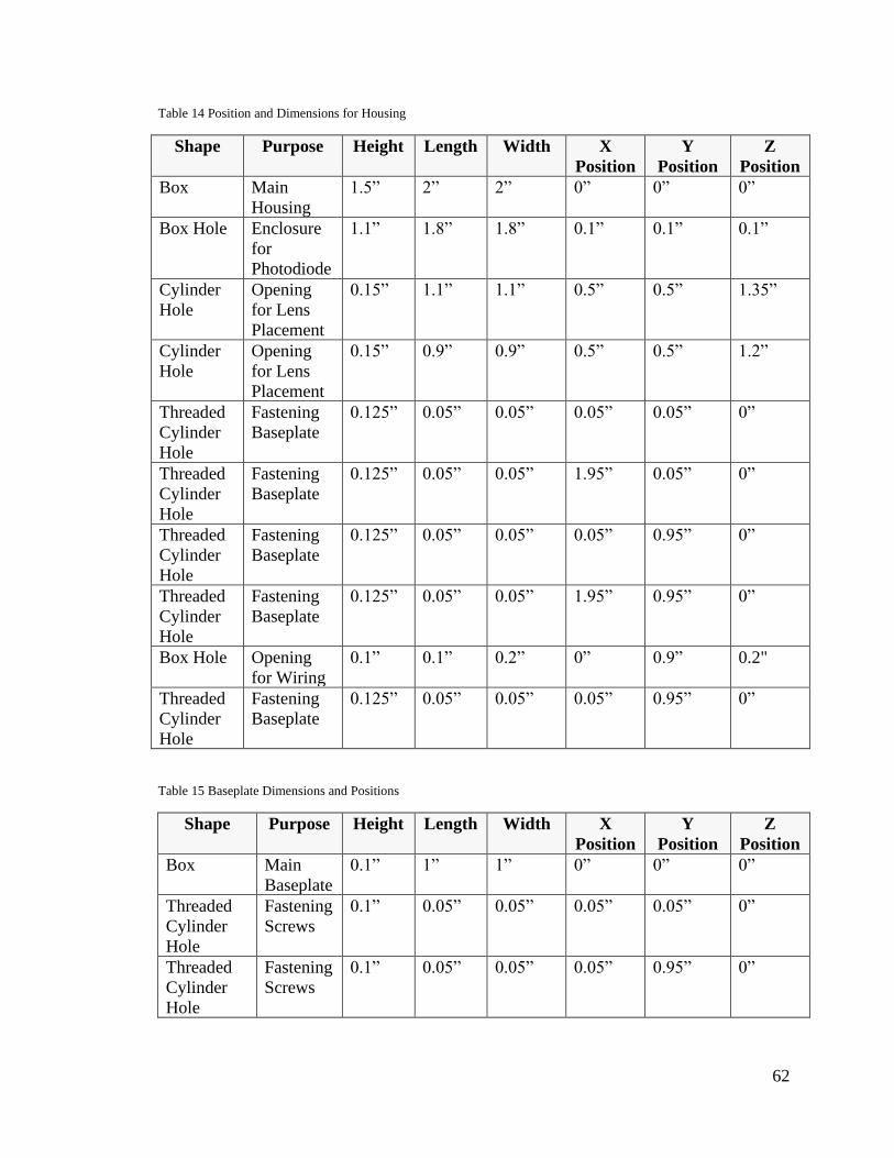
62
Table 14 Position and Dimensions for Housing
Shape Purpose Height Length Width X
Position
Y
Position
Z
Position
Box Main
Housing
1.5” 2” 2” 0” 0” 0”
Box Hole Enclosure
for
Photodiode
1.1” 1.8” 1.8” 0.1” 0.1” 0.1”
Cylinder
Hole
Opening
for Lens
Placement
0.15” 1.1” 1.1” 0.5” 0.5” 1.35”
Cylinder
Hole
Opening
for Lens
Placement
0.15” 0.9” 0.9” 0.5” 0.5” 1.2”
Threaded
Cylinder
Hole
Fastening
Baseplate
0.125” 0.05” 0.05”
0.05” 0.05” 0”
Threaded
Cylinder
Hole
Fastening
Baseplate
0.125”
0.05”
0.05”
1.95” 0.05” 0”
Threaded
Cylinder
Hole
Fastening
Baseplate
0.125”
0.05”
0.05”
0.05” 0.95” 0”
Threaded
Cylinder
Hole
Fastening
Baseplate
0.125”
0.05”
0.05”
1.95” 0.95” 0”
Box Hole Opening
for Wiring
0.1” 0.1” 0.2” 0” 0.9” 0.2"
Threaded
Cylinder
Hole
Fastening
Baseplate
0.125”
0.05”
0.05”
0.05” 0.95” 0”
Table 15 Baseplate Dimensions and Positions
Shape Purpose Height Length Width X
Position
Y
Position
Z
Position
Box Main
Baseplate
0.1” 1” 1” 0” 0” 0”
Threaded
Cylinder
Hole
Fastening
Screws
0.1” 0.05” 0.05”
0.05” 0.05”
0”
Threaded
Cylinder
Hole
Fastening
Screws
0.1” 0.05”
0.05”
0.05”
0.95” 0”

63
Table 15 Continued
Threaded
Cylinder
Hole
Fastening
Screws
0.1” 0.05”
0.05”
0.95” 0.05”
0”
Threaded
Cylinder
Hole
Fastening
Screws
0.1” 0.05”
0.05”
0.95” 0.95” 0”
Cylinder
Hole
Mounting
Photodio
de onto
the
Baseplate
0.1” 0.05”
0.05”
0.5” 0.35” 0”
The Circuit design of our portable sensors were all made generically so that they can be
used in many different applications. Our sensor boards can be installed with any 3.3V
sensor and can support voltage inputs of 3.3VDC to 12VDC. This generalization and
uniformity will help us lower cost and expand our product line in the future.
Figure 27. Sensor Board Schematic

64
Figure 28. Sensor Board PCB Layout
The following table is the Bill of Manufacturing our sensor boards. These boards were used
for both the fire hazard detector and the motion sensors.
Table 16 BOM Sensor Board
Name Designator Footprint Quantity Manufacturer Part Manufacturer Price
LM2596 U1 LM2596 1 LM2596M LC Tech $ 1.60
10k Resistor R1, R2,
R3, R4, R5
AXIAL-
0.3
5 Generic Generic $ 0.01
ESP-12F U4 ESP-12F 1 ESP-12F Expressiff $ 1.22
2in x 3in PCB PCB PCB 1 SD2019G14S Advance Circuits $ 10
220 Resistor R7 AXIAL-
0.3
1 Generic Generic $ 0.01
SMD
470h Inductor
H1 SMD 1 470h SMTelectronics $ 0.10
25V
100uf Capacitor
C1, C2 SOT 2 Generic Generic $ 0.05
Push
Button Switch
U4, U5 DIP-4 2 PBS12 EVERLIGHT $ 0.02
Total $13.01

65
5.2. Hardware Design Lessons Learned
Certain design specifications were ultimately scrapped after assembly and testing. The
current sensor could not make it into our application because we discovered late in the
game that the analog sampling was interfering with our MQTT hub connection. Some of
our devices were not receiving enough power to support every component on the board,
we were able to fix this by removing some of the LEDs that were only needed to visualize
which relays were being turned on. PCB boards were designed in EagleCAD and order
through Advanced Circuits. We were able to get high quality boards but the cost of the
boards were excessive compared to overseas manufacturers. Had we realized those costs
early we would have planned for using the Chinese companies. This may have a slight
affect in overall quality but it would have dramatically reduced our cost. One of our
requirements is to make the devices as cost efficient as possible. Using US manufactures
unfortunately would hurt our bottom line.
The size of the boards ended up being rather cumbersome. The vast majority of components
we had on hand required through-hole soldering. This made assembly a lot easier but also
increased the size of our components making it harder to fit in the space we needed. We
believe that each board could see up to 50% reduction in size my using only SMD
components. This would allow us to meet our goal of having standard sizes for our plug
and play devices.
5.3. Software Design Details
5.3.1. Microcontroller Components Software
The Following diagram displays the general function of our system. In this section we will
define the software necessary for features like the Smart Switch, Outlet, Flame Detector,
and Motion Detector to have the desired functionality and to be able to communicate with
the system HUB. Illustrated in the diagram is the various input and output channels of the
system. The switch will have to make TCP responses to the hub as well as control the
connected appliance. Same goes for the outlet. The flame and motion detectors will not
require inputs from the system. Their task will simply be to upload sensor data at various
intervals. This will be set up using interrupts to make sure those products have minimum
energy consumption since the will be battery powered.

66
Figure 29. Function Diagram
The next figure will be our software process. To provide a seamless set up will we be using
the WPS connection of modern routers to connect our devices to the local area network.
When first powering up the devices will be on stand-by mode awaiting their WPS button
to be pushed, starting the process of connecting to the router who’s WPS button was also
pushed. It is recommended that the router’s button be pushed first so that it is in search
mode when the device’s button is pushed. The device will attempt to connect to the router
for some period. If no connection occurs the device will return to stand-by mode. If
connected, the device will multicast an encrypted “Available” message until the HUB
responds with a link request. The device will send out its local IP and the HUB will register
the device to the system. Configuring the device will be left up to the user, through the
Web UI. For these four devices the command loop will be generally the same. They will
either send back sensor data when those interrupts are triggered, or they will respond to
commands when the HUB sends requests. Though all 4 devices will share hardware, the
sensors will have a flag that block any commands. We only want these sensors to send back
data. The HUB will have to interpret and create the logic for using the data.

67
Figure 30. Software Process
We will be using the Arduino IDE to flash all the MCUs. This IDE uses C++ scripts so we
will make have a class structure for our code. We will generally have 4 classes:
• WPSConnect: Responsible for connecting to router after push button interrupt.
• HUBLink: Responsible for handling the link between the device and HUB once a
LAN connection has been established
• CommandLoop: Main loop. Will handle the functionality of the device. Devices
not wired to an external power source will use interrupts for their logic so they can
remain in low power mode.
• Interrupts: Class that will handle all interrupt logic.
Three of the classes will share the same connection object. The following class diagram
will prototype our code structure. Not all member variables are defined. We will have to
go through the ESP8266 library to see what kind of built in functionality is available. There
needs to be a consorted effort to use as much of the built-in functionality from the IDE and
the MCU libraries. Arduino provides a board manager that handles most of the embedded
code. PIN mapping and setting registers can be an arduous task and should be avoided.
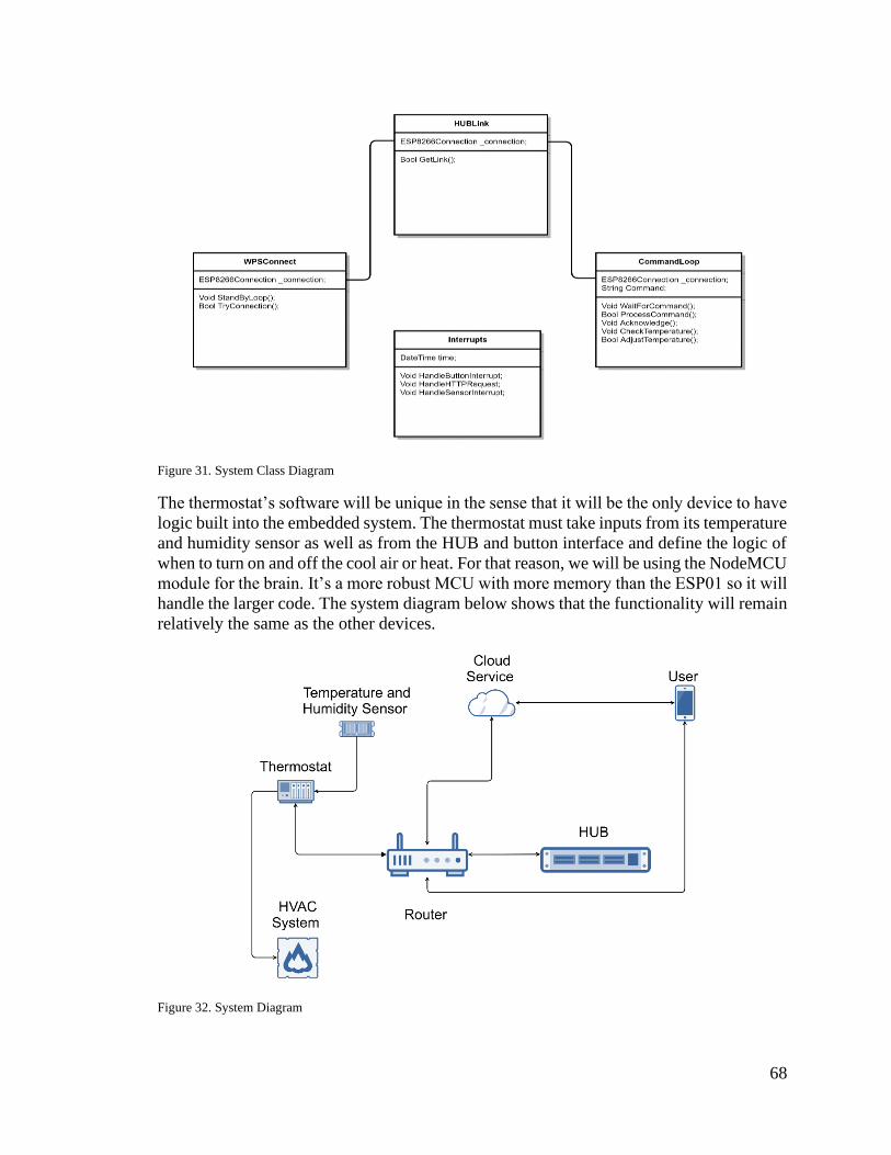
68
Figure 31. System Class Diagram
The thermostat’s software will be unique in the sense that it will be the only device to have
logic built into the embedded system. The thermostat must take inputs from its temperature
and humidity sensor as well as from the HUB and button interface and define the logic of
when to turn on and off the cool air or heat. For that reason, we will be using the NodeMCU
module for the brain. It’s a more robust MCU with more memory than the ESP01 so it will
handle the larger code. The system diagram below shows that the functionality will remain
relatively the same as the other devices.
Figure 32. System Diagram

69
The startup process, shown in the following flowchart, will begin like the four other devices
with one difference, during the command loop the thermostat will have to adjust for
temperature changes and schedule changes since we have defined a requirement that a
schedule can be set. The thermostat will also need to be able to respond on command to
setting changes done by either HUB requests or push-button interrupts when the user sets
a new target temperature manually. The technical details for achieving this logic will be
decided during the second phase of this project
Figure 33. Thermostat System Flowchart

70
5.3.2. Considerations for Network Connection Between Hub and LAN
Ethernet Connection
There are several benefits to making use of a direct wired Ethernet connection when it
comes to means by which the hub might be connected to the user’s LAN. When it comes
to considerations of latency, reliability, and bandwidth, it’s difficult to beat a cable
connection, as wired connections are not beholden to considerations of wireless
interference or signal degradation due to walls or other structures. However, convenience
is lost when choosing this option, especially if the user wishes to install the device in an
area of the home which is a large distance from the location of the user’s router or network
hub. Because we do not expect the bandwidth usage of the device to be particularly high,
the gains in latency and transfer rate are not of great enough value to the project to make
this the sole means of connecting the hub to the local network. However, because the
Raspberry Pi 3 does possess an Ethernet port, it would not be detrimental to provide
Ethernet as an optional means of connecting the device to the local network.
Wi-Fi (WPA2 PSK)
WPA2 using a pre-shared key is one of the most common means of securely providing
access to a home-based local-area-network currently in use and is generally considered to
be adequate for personal security, due to the low number of individuals expected to see and
make use of the pre-shared key in such an environment. In the case of an organization-
level wifi deployment, PSK is often undesirable due to the risk of a singular employee or
other authenticated individual sharing the key with a third-party, causing said organizations
to more often opt for WiFi-PEAP, as it provides individualized authentication which may
be easily revoked or traced to an individual in the event of a breach. Though the pre-shared
key is used for initial authentication between the network and the client, in order to limit
the exposure of this master key, a four-way handshake takes place during authentication in
which a pairwise-transient key is computed which is then used to encrypt messages for the
remainder of the session.
Figure 34. Diagram of four-part WPA2 Handshake

71
One issue with using pre-shared key-based authentication lies in the fact that we currently
plan for the hub device to be completely headless, requiring no display or input peripherals
to make use of due to the online interface. However, WPA2-PSK based authentication
presents a catch-22 in this case. If the user is to gain access to the device via the web
interface, it must first acquire an internet connection, but since the device is meant to have
no input peripherals, this means that there would be no reliable way for the user to input
the pre-shared key specific to their network in order to allow the device to acquire a
connection.
Wi-Fi WPS (WiFi-Protected Setup)
One system which might help to sidestep the issues with authentication is WiFi-Protected
setup (WPS). This protocol is designed to provide a ‘push-button authentication’ which
allows a single device to connect to and authenticate with the wireless network for a short
time following the activation of a special mode on the router via the push of a button. This
would solve the above issue, as there would be no need for any means of providing the hub
device with a pre-shared key for the wireless network. Once the device has been paired
once, need for further authentication would also be eliminated.
However, this method does carry several security issues [9]. Firstly, due to flaws in the
means by which WPS PINs are rejected, WPS-based security can be brute-forced, with the
time required to brute force being manufacturer-specific and largely dependent on whether
said manufacturer has implemented timed lockouts following an excessive number of
failed attempts.
Another significant vulnerability, the severity of which depends on the specific
implementation, lies in the fact that some routers have been reported to calculate their WPS
PIN numbers from the hardware MAC address of the router itself. This is troubling
because, in such cases, a brute force attack is not even required to break the network’s
security, as once the process for computing the PIN is known, it can simply be computed
via the same process client-side and then sent to the router for access.
Finally, if the WPS-enabled router is not kept in an area which is physically secure, there
is a risk of someone with physical access to the device, but who is not meant to be making
use of the network, making use of the authentication push-button to achieve authentication
with the network. For our use case, this security concern is of little severity when compared
to the two above, as such a compromise in security would mean that the intruder already
has access to the interior of the user’s home anyways.
Still, given the desire to reduce the cost and complexity of the system by avoiding the need
for user I/O peripherals on the hub makes WPS an attractive option than Ethernet or pure
WPA2-PSK based authentication. Thus, we plan to offer it as an option for configuration
if the user wishes to make use of it regardless of the risks, and offer Ethernet based
connection as the more secure method of installation. If WPS proves not to be viable,
because the security concerns are too great or otherwise, it is more likely that we will fall
back to using a wired ethernet connection than it is that we will add an interface for entering
a pre-shared key, as the latter case would be a significant departure from the current

72
hardware design outlined in the project and would act to significantly increase the cost of
the device.
Figure 35. Example of a typical router WPS authentication button
5.3.3. Networking Overview
To allow the user access to in-house systems from anywhere with an internet connection,
it was decided that a web server would act as a go-between between the user’s device and
the system hub. This webserver will provide an HTTP-Based interface to the smart home
hub, carry out authentication and access-control tasks by maintaining a user login database
which associates users with their specific home devices. The hub will communicate with
the server and both receive configuration information and user-commands and will
likewise send information regarding the current status of sensors and devices within the
home to the serve, so that this information may then be relayed to the client via the user
interface. The hub will broadcast a Wi-Fi direct signal which will allow devices to connect
to it which will ensure that, from the point of view of said devices, the hub will maintain
the same IP address. An authentication system will be implemented between the server and
the hub to ensure that the hub cannot be accessed without access to the proper user account.
Figure 36. Network Diagram

73
The hub will retrieve new information regarding the state of the devices registered in the
database by polling at regular intervals for changes made to said devices.
The other option for networking is to make the communication between the hub and the
server completely webservice-based, which bears numerous advantages. This would get
around the issue of network address translation completely by allowing the hub to simply
check in and maintain a regular connection with the server. There are also a wide variety
of well-supported webservice types such as SOAP, AJAX, etc. Webservices are also
helpful in the sense that they make it simpler to transmit and sort through well-formatted
data, and oftentimes involve transmission done in XML or other forms of markup-
language. Whereas raw internet-based data transmission methods (websockets, etc) would
require that data be sent in a stream of one sort or another and sorted out later, a webservice-
based solution will allow for all requested or sent data to be easily organized in a markup,
from which relevant information can be isolated as required.
The only potential drawback of such a system is that it would require that the hub maintain
a consistent connection to the server in order to ensure that commands from the user can
be received in a timely manner, which has the potential to increase power usage. All the
same, considering the fact that out of all the devices on the network, the hub is the least
likely to be connected to battery-power, it seems to be an acceptable choice as the increase
in power consumption would be negligible for a wall-outlet powered device and will not
have a significant impact on the performance of any battery-operated devices which are
connected to the smart home system.
5.3.4. Device Discovery
The hub device will be responsible for facilitating discovery and connection with other
devices on the network. Presuming an option by which the hub and the smart-home
devices which it controls are both connected directly to the user’s LAN, there are
numerous ways which device discovery may be achieved, but many are either slow or
require extra configuration that would prove cumbersome to the end-user. To that end,
we have opted to avoid a setup where smart home devices which make up the system
connect to the user’s wifi, instead connecting directly to the hub via a peer-to-peer direct
connection. However, the methodologies considered for device discovery on the network
are listed below, and the most enticing was chosen to be most useful for an in-home
application on a relatively small LAN with a single subnet, and to minimize extra work
and configuration required from the user. The options considered are outlined below:
ICMP ECHO request (Ping) scan
The primary benefit to this technique is its simplicity and reliability, as it is supported by
practically every device that would be deployed on a private LAN and is a rock solid,
ubiquitous part of the networking infrastructure. However, there are significant
downsides to this option, the most important being that it is slow. A full scan of a 255-
address network space can take upwards of ten seconds and following the discovery of a
list of devices connected to the network, those devices which are configured to be
workable components of the smart-home system must then also be differentiated from
other, unrelated devices on the network through other means. For these reasons, this is
not an ideal method for discovering devices within the network for our purposes.
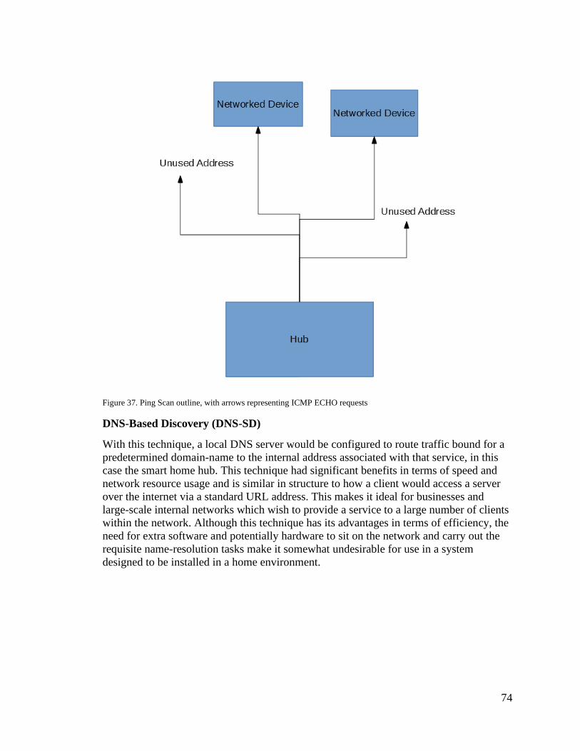
74
Figure 37. Ping Scan outline, with arrows representing ICMP ECHO requests
DNS-Based Discovery (DNS-SD)
With this technique, a local DNS server would be configured to route traffic bound for a
predetermined domain-name to the internal address associated with that service, in this
case the smart home hub. This technique had significant benefits in terms of speed and
network resource usage and is similar in structure to how a client would access a server
over the internet via a standard URL address. This makes it ideal for businesses and
large-scale internal networks which wish to provide a service to a large number of clients
within the network. Although this technique has its advantages in terms of efficiency, the
need for extra software and potentially hardware to sit on the network and carry out the
requisite name-resolution tasks make it somewhat undesirable for use in a system
designed to be installed in a home environment.

75
Figure 38. Example of DNS-SD based discovery of a network service
UDP Broadcast-based Discovery
UDP Broadcast can be used to send UDP packets to all computers on the LAN
simultaneously, and by programming the devices on the network to respond to the UDP
packets in question, they can thus all be identified and logged by the hub. This method
has the advantages of being much faster than a network scan while involving less
overhead yet is simultaneously less complex and configuration-intensive than the DNS-
SD method outlined above. The primary downsides to this method include the fact that it
generates more network traffic than the DNS-SD based method and will also not work
across multiple subnets, but in the home-LAN environment in which we are planning to
deploy the system, these concerns are relatively marginal. This goes doubly so when
considering the fact that the hub will only need to discover new devices on occasion,
either during initial setup or when new devices are installed in the household.
In figure 36, a general diagram of how UDP-Broadcast based device discovery can be
achieved is depictured. The packet sent to the routing device is transmitted to all the
devices on the network (shown as blue arrows), and then only those devices programmed
to respond to said packet reply to the hub device, which can then log any relevant data (IP
Addresses, MAC addresses, etc) for later use in communicating with said devices.

76
Figure 39. Example of UDP-Broadcast
Another method by which devices which are to be controlled by the hub might be
connected involves the use of a Wi-Fi direct connection between the hub and the devices
themselves. This approach brings with it significant advantages over the plan which has
the devices connect to the hub via the user’s LAN. As outlined in the networking overview,
creating pre-configured headless devices designed to connect to a secured wireless network
presents several challenges related to how to relay the necessary security details to the
device in question. Connecting directly to the hub via a Wi-Fi direct connection eliminates
these issues, as the devices can be pre-configurated with the necessary details required to
make a connection with the hub, and thus need not concern themselves with the details of
the user’s wireless network.
This method is also beneficial in the sense that it renders the need for a robust device-
discovery method moot. Because devices can be expected to connect to the smart-home
system via a Wi-Fi direct connection, the IP address of the hub itself can be expected to
remain consistent, allowing the devices to connect to the MQTT broker running on said
device without issue. This also simplifies the configuration of the smart-home devices
connected to the hub, as there is no longer any need for them to connect with the hub to
acquire its IP address. In this case, the devices need only be pre-configured with the SSID
of the network the hub broadcasts and the relevant security information.

77
Given the greater simplicity of this solution as opposed to the alternatives outlined above,
we have opted to simply make use of a direct Wi-Fi connection to the hub rather than
carrying out the network discovery-based solutions outlined further above.
A Raspberry Pi 3 can be configured to act as a Wi-Fi access point via the use of WPA-
Supplicant and the proper configuration profiles, and the addition of an extra Wi-Fi adapter
can serve to further simplify this process. To do this, the default dhcpcd based networking
service must be disabled and systemd-networkd must be enabled. From there, one of the
network interfaces must be configured as an access point, and the other as a client using
standard wpa_supplicant configuration files. For WPS setup, the client interface should be
configured as a WPS client. For ethernet setup, an ethernet cable needs only be plugged
into the ethernet jack of the device.
5.3.5. Client-Server Communication
Having a clearly-defined API for communication between the client and the server is
paramount, as it will not only determine what networking functionality is available to the
relevant devices, but also serve as a blueprint for what methods and functions must be
developed in order to produce the desired functionality on relevant machines. There are
numerous key features which must be included within the client-server API to ensure that
the system can provide the functionality outlined in the project goals and objectives. Since
we have opted to develop this API as a web service, there are several options available, the
most popular among them being SOAP and REST.
5.3.5.1. Simple Object Access Protocol
SOAP (Simple Object Access Protocol) carries out information interchange using the XML
format and is by and large the more mature protocol for developing webservices. It offers
a higher degree of complexity than is available to REST, including storing state across
multiple transactions (though SOAP is stateless by default) and is functionality-driven by
design, I.E. based on the paradigm of creating functions which perform a given action or
retrieve/receive a given piece of data. SOAP has its advantages and sees heavy use in both
legacy systems and the financial sector, but due to its use of XML and because of the extra
rules and complexity implicit in the protocol, it is more resource-intensive and can often
be more difficult to use. Likewise, since most of the communication we expect to be doing
is more data-driven than functionality driven, SOAP is not, by its nature, the best fit for the
type of work we expect our system to be doing.
5.3.5.2. React JavaScript
As the development process progresses, it is becoming more clear which technologies we
will be likely using in our system. As we have shown in figure 30, in order for something
like so to be achieved it is likely we will also need to implement in our front-end
frameworks another library, more specifically React. React is a JavaScript library
developed by Facebook to streamline the process of creating interactive user interfaces.
We have said that we want to create a dashboard for our user where they will be able to
see, for example, the power usage of their devices. This is a perfect example of where React
could be used to display such information. Say we display this information in a graphical

78
way, as shown in the mockup in figure 30. In order to correctly populate the graph with
their specific information we could use React to dynamically display it.
For our final build we decided to not go forward utilizing React, as we were able to achieve
similar results with the use of ‘pure’ Javascript. Also, this allowed us to focus on perfecting
other features in our system.
The REST (Representational State Transfer) webservice protocol has been selected as the
protocol upon which to build the client-server communication API. Being an system for
representing data clearly in various formats such as text, JSON, and XML, REST is an
ideal candidate for the construction of our API because, unlike SOAP, messages data can
be encoded in a JSON format which is significantly more lightweight than SOAP’s more
bandwidth-intensive XML format, which will result in faster communication and lower
bandwidth usage overall. REST is also better suited to tasks which involve the retrieval
and management of data, rather than the more functional-transactional orientation of
SOAP. This feature makes it highly effective at meeting our needs, as the client side hub
will need to be able to provide the server with a clear and complete listing of all the smart-
home items on the user’s network which includes information about the type, functionality,
and status of said items, and this type of information lends itself readily to being
encapsulated in an object or structural datatype which serves to define the real-world item
to which it is associated.
Although REST-based systems can transmit data in a number of formats, we’ve chosen
JSON as the primary format because, as stated above, it is not only significantly less
verbose (and therefore, easier to type if necessary and also less bandwidth-intensive) than
XML, but can also be parsed more quickly by most software, freeing up system resources
which would otherwise be spent on the task of parsing incoming data.
5.3.5.3. Django REST Framework
Since we have already decided to use Python with Django as the basis of our server
backend, it makes sense to use the Django REST framework for the implementation of the
API, as it fits with our pre-existing software ecosystem and provides the required service
by design. The Django rest framework provides useful abstraction and tools which will
help to ensure that the relevant software produced can both be completed in a timely
manner and reduce the frequency of technical faults which might otherwise arise.
Since we decided to not use React, we decided as well to not implement a REST
framework, as the communication between the frontend and backend was made in a
different way.
5.3.5.4. Vue.js
As an alternative to the React framework. We could also use in our system another
framework called Vue.js. Similar to React it is used to easily create user interfaces,
however instead of using JavaScript-based templates, it uses HTML-based templates.
Because of that, we believe that integrating Vue with our current back-end framework will
be easier than utilizing React since Django also uses HTML templates.
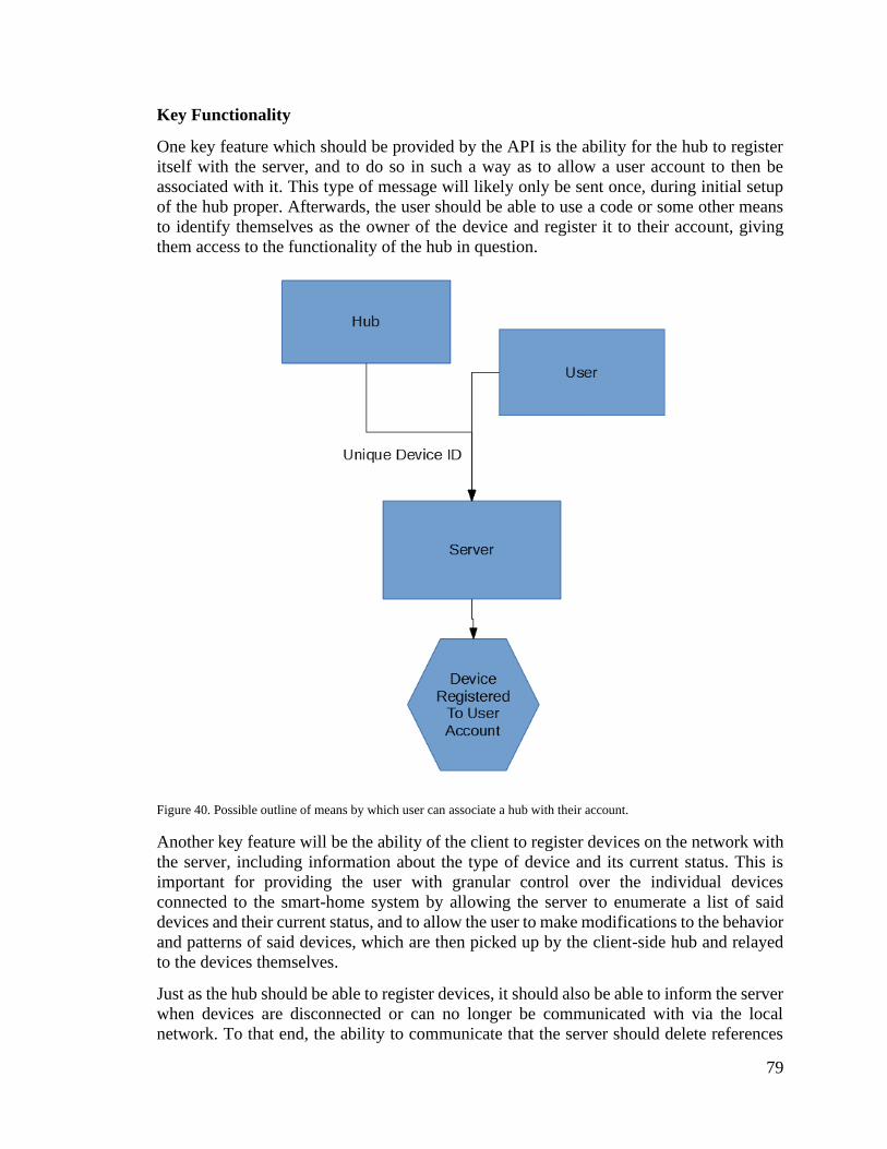
79
Key Functionality
One key feature which should be provided by the API is the ability for the hub to register
itself with the server, and to do so in such a way as to allow a user account to then be
associated with it. This type of message will likely only be sent once, during initial setup
of the hub proper. Afterwards, the user should be able to use a code or some other means
to identify themselves as the owner of the device and register it to their account, giving
them access to the functionality of the hub in question.
Figure 40. Possible outline of means by which user can associate a hub with their account.
Another key feature will be the ability of the client to register devices on the network with
the server, including information about the type of device and its current status. This is
important for providing the user with granular control over the individual devices
connected to the smart-home system by allowing the server to enumerate a list of said
devices and their current status, and to allow the user to make modifications to the behavior
and patterns of said devices, which are then picked up by the client-side hub and relayed
to the devices themselves.
Just as the hub should be able to register devices, it should also be able to inform the server
when devices are disconnected or can no longer be communicated with via the local
network. To that end, the ability to communicate that the server should delete references
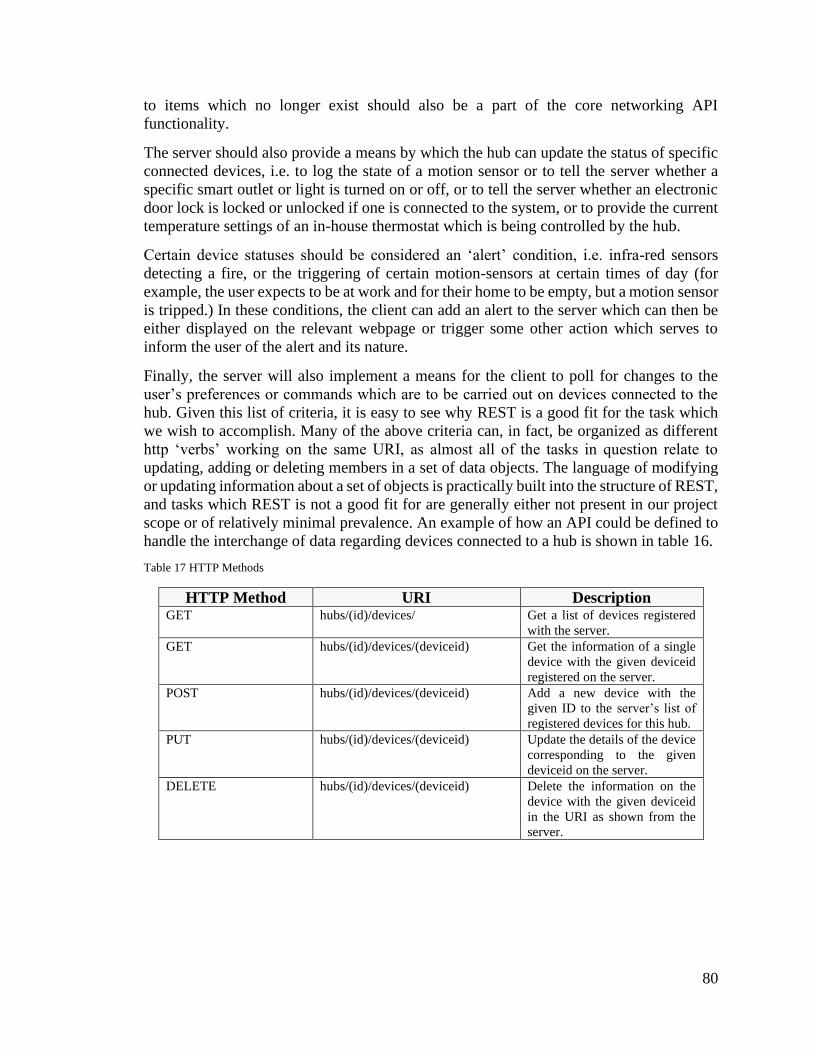
80
to items which no longer exist should also be a part of the core networking API
functionality.
The server should also provide a means by which the hub can update the status of specific
connected devices, i.e. to log the state of a motion sensor or to tell the server whether a
specific smart outlet or light is turned on or off, or to tell the server whether an electronic
door lock is locked or unlocked if one is connected to the system, or to provide the current
temperature settings of an in-house thermostat which is being controlled by the hub.
Certain device statuses should be considered an ‘alert’ condition, i.e. infra-red sensors
detecting a fire, or the triggering of certain motion-sensors at certain times of day (for
example, the user expects to be at work and for their home to be empty, but a motion sensor
is tripped.) In these conditions, the client can add an alert to the server which can then be
either displayed on the relevant webpage or trigger some other action which serves to
inform the user of the alert and its nature.
Finally, the server will also implement a means for the client to poll for changes to the
user’s preferences or commands which are to be carried out on devices connected to the
hub. Given this list of criteria, it is easy to see why REST is a good fit for the task which
we wish to accomplish. Many of the above criteria can, in fact, be organized as different
http ‘verbs’ working on the same URI, as almost all of the tasks in question relate to
updating, adding or deleting members in a set of data objects. The language of modifying
or updating information about a set of objects is practically built into the structure of REST,
and tasks which REST is not a good fit for are generally either not present in our project
scope or of relatively minimal prevalence. An example of how an API could be defined to
handle the interchange of data regarding devices connected to a hub is shown in table 16.
Table 17 HTTP Methods
HTTP Method URI Description GET hubs/(id)/devices/ Get a list of devices registered
with the server.
GET hubs/(id)/devices/(deviceid) Get the information of a single
device with the given deviceid
registered on the server.
POST hubs/(id)/devices/(deviceid) Add a new device with the
given ID to the server’s list of
registered devices for this hub.
PUT hubs/(id)/devices/(deviceid) Update the details of the device
corresponding to the given
deviceid on the server.
DELETE hubs/(id)/devices/(deviceid) Delete the information on the
device with the given deviceid
in the URI as shown from the
server.

81
JSON Object Format
Because the user will have the opportunity to install multiple different types of device, with
different functions, feedback, and formats, the system will need to be able to handle and
transmit all information relevant to the device in question. However, since the various
devices used as part of the system will each have their own data requirements (I.E. an air
conditioner unit will require information related to whether the unit is currently on, what
the desired temperature is, etc) and because it is in our best interest to prevent the footprint
of JSON messages between the client and server from growing with every new type of
device added, it makes sense to format our JSON device objects in such a way that the
consist of an outer wrapper which contains all the data which is shared by all device objects
and information as to what type of device is being represented, and an inner nested object
which contains all of the relevant device-specific data.
This should allow for the data footprint to remain relatively small and consistent, while
still providing the flexibility necessary to represent the myriad supported devices which
must be controlled by the smart home system.
The structure which will be used by the device objects will be outlined in detail here once
it has been decided upon and finalized, and may be extended during development to meet
the needs of the system if any new fields prove to be necessary to provide the desired
functionality.
Consistency will need to be maintained between the data that the server expects and what
the client sends, mostly because the server will be performing validation on JSON which
is received through the REST API, and thus any changes to the data required by the server
will likewise need to be accompanied by changes to relevant code on the client-side. In the
event that a request to the server is invalid, the Django REST framework will automatically
provide fitting HTTP responses which detail the error in question, which should assist in
the process of debugging any such errors.
Below in figure 37 is an example of how a POST method transaction involving devices
can be carried out via the API, with device-type specific information included in the
overarching device JSON object as an embedded object, which in turn possesses the
requisite members to describe the device in question. Following a successful POST
transaction, the client receives a JSON object which contains the device ID assigned to the
registered device on the server which can be recorded and used to refer to that specific
object in all future communications.
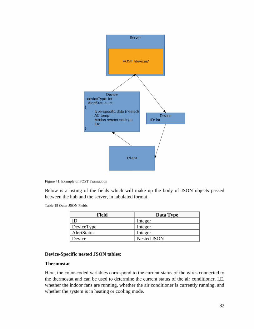
82
Figure 41. Example of POST Transaction
Below is a listing of the fields which will make up the body of JSON objects passed
between the hub and the server, in tabulated format.
Table 18 Outer JSON Fields
Field Data Type
ID Integer
DeviceType Integer
AlertStatus Integer
Device Nested JSON
Device-Specific nested JSON tables:
Thermostat
Here, the color-coded variables correspond to the current status of the wires connected to
the thermostat and can be used to determine the current status of the air conditioner, I.E.
whether the indoor fans are running, whether the air conditioner is currently running, and
whether the system is in heating or cooling mode.
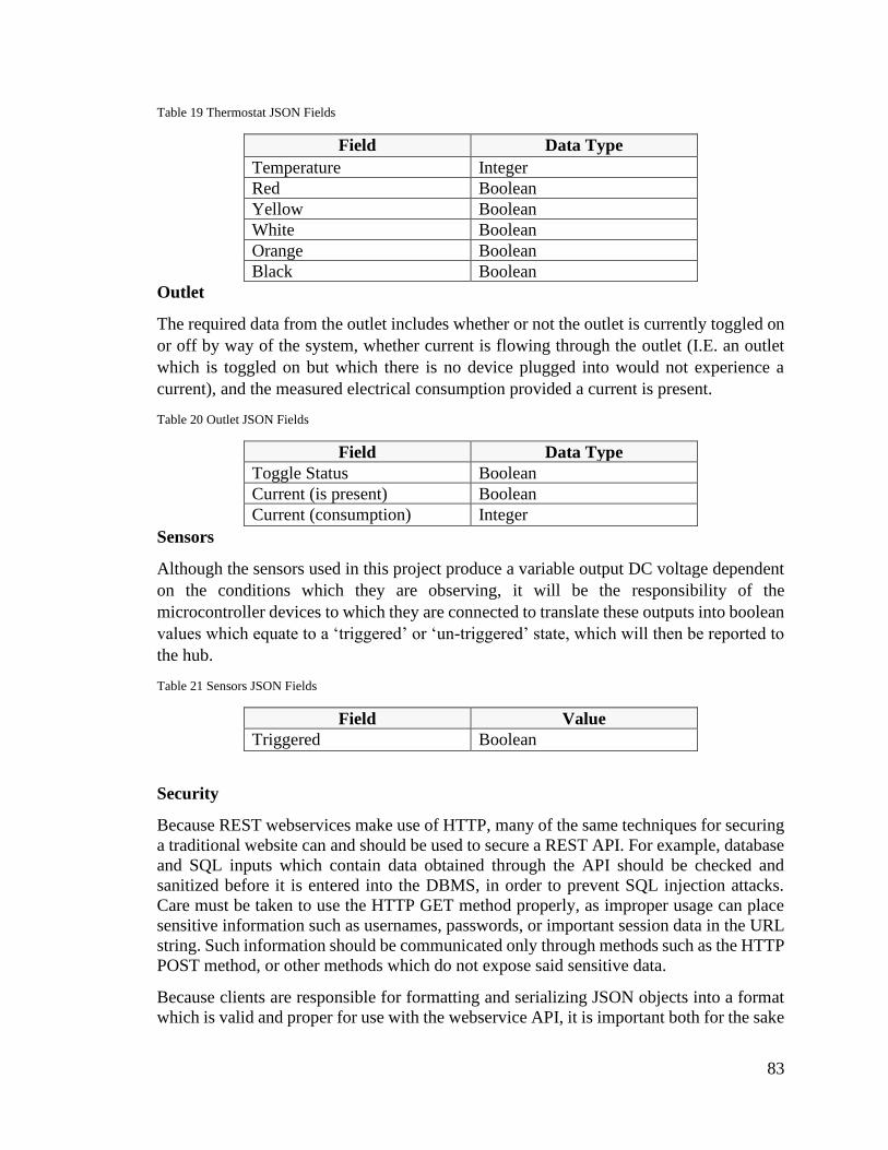
83
Table 19 Thermostat JSON Fields
Field Data Type
Temperature Integer
Red Boolean
Yellow Boolean
White Boolean
Orange Boolean
Black Boolean
Outlet
The required data from the outlet includes whether or not the outlet is currently toggled on
or off by way of the system, whether current is flowing through the outlet (I.E. an outlet
which is toggled on but which there is no device plugged into would not experience a
current), and the measured electrical consumption provided a current is present.
Table 20 Outlet JSON Fields
Field Data Type
Toggle Status Boolean
Current (is present) Boolean
Current (consumption) Integer
Sensors
Although the sensors used in this project produce a variable output DC voltage dependent
on the conditions which they are observing, it will be the responsibility of the
microcontroller devices to which they are connected to translate these outputs into boolean
values which equate to a ‘triggered’ or ‘un-triggered’ state, which will then be reported to
the hub.
Table 21 Sensors JSON Fields
Field Value
Triggered Boolean
Security
Because REST webservices make use of HTTP, many of the same techniques for securing
a traditional website can and should be used to secure a REST API. For example, database
and SQL inputs which contain data obtained through the API should be checked and
sanitized before it is entered into the DBMS, in order to prevent SQL injection attacks.
Care must be taken to use the HTTP GET method properly, as improper usage can place
sensitive information such as usernames, passwords, or important session data in the URL
string. Such information should be communicated only through methods such as the HTTP
POST method, or other methods which do not expose said sensitive data.
Because clients are responsible for formatting and serializing JSON objects into a format
which is valid and proper for use with the webservice API, it is important both for the sake
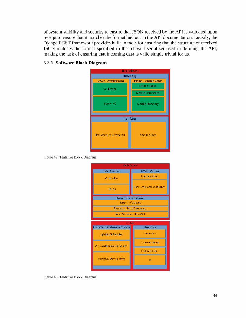
84
of system stability and security to ensure that JSON received by the API is validated upon
receipt to ensure that it matches the format laid out in the API documentation. Luckily, the
Django REST framework provides built-in tools for ensuring that the structure of received
JSON matches the format specified in the relevant serializer used in defining the API,
making the task of ensuring that incoming data is valid simple trivial for us.
5.3.6. Software Block Diagram
Figure 42. Tentative Block Diagram
Figure 43. Tentative Block Diagram

85
5.3.7. Auxiliary Services
We have previously discussed in Section 3.2 the different cloud services available for use
regarding the hosting of our web server. Our top two candidates were Digital Ocean and
Amazon Web Services. We have said we would be using both of these providers in unison
and that is still the case. With AWS, we are able to implement, for example, a feature where
the user of our system will be able to reset their password through their email, and this is
possible because of the integration of our web server provider and an AWS service
provided by AWS, called Simple Email Service (SES). Utilizing SES, we are able to setup
the domain name of our system to utilize records provided by AWS which will route the
email messages pertinent to password reset action.
Another way we will be utilizing services provided by AWS within our project is by using
Amazon Simple Storage Service (S3) to serve our users with the static files for our website.
Even though our back-end framework is capable of doing so, it is recommended by them
that for deployment of a project that will be used in production, such as ours, that the use
of third-party services to serve end users static content to be preferred. That
recommendation is given because the Django’s system is inefficient and insecure,
according to their documentation [8].
5.3.8. System Security
Security is of utmost importance for us and the future users of our system. It is important
to note, that by providing this service to our end users, we are not providing, however, a
security system. Rather, we will do our best to provide a secure system that should, by
utilizing tools already established in the security ecosystem provide an environment that
will be immune to most common intrusion attacks, for example unauthorized user access.
5.3.9. Class Diagrams
In this section we will provide the reader with Unified Modeling Language (UML)
diagrams related to how a user account, will be organized in the database system of our
choice. In future versions of this document, we will also include diagrams for other aspects
of our web application.
Figure 44. User UML Diagram

86
In figure 41, it is shown a Use Case Diagram of the user registration and login as well
dashboard and profile management. The user if not registered will have the option to create
a new account. Once such step is completed, the user will be taken to their homepage where
they will have access to the dashboard where they will be able to control the devices
installed within their system, as well the ability to check the usage of such devices. Another
option provided to the user, will be profile management, where for example they will be
able to change their email address or reset their password.
Figure 45. User and Dashboard Management
5.3.10. User Interface Overview
We believe that usability of our system plays big a part in the overall project. As such, we
have spent careful time in consideration on how the user interface will be constructed, and
which elements we can implement to have an easy-to-use system which can attend all of
our user base. As we have previously mentioned, we have a few options for the front-end
web framework being used. In figures 46 and 47, we can see different examples of how we
imagine the login web page is going to look like for the final version of the project.

87
Figure 46. Login Layout Utilizing Materialize CSS
Figure 47. Login Layout with Material Design for Bootstrap
Both of these designs are considered appealing by us, and they are both very similar to
what we envision as our final design. As the development phase begins, we will keep these
ideas in mind and decide which one will work better with the other sections of our web
application.
With some parts of development processes already started, we can now discuss more about
the user interface. Mainly, we will discuss about the interface for account management. In
figures 48 and 49, we can see how we have implemented our web framework of choice,
Material Design for Bootstrap, to create a login and a registration page.
We have decided to utilize a very simple interface. We want to provide our user with a
clutter free workspace which can still attend all their needs. If time permits, we will also
allow our users to login with their social media accounts to further streamline the process.
Doing so, we will be able to reduce the number of accounts a user has to remember. The
expected layout for our login page can be seen in figure 48 below.

88
Figure 48. Login Form
The same idea was applied to our registration form. In figure 50 we can see one
implementation of the current registration page. As shown, for now, a user needs to create
a username, provide their first and last names, create a secure password, and provide us
with their email address. After submitting the form, the user will receive in their mailbox
a confirmation email from our system, asking them to verify their newly created account.
This will serve as an extra security measure to prevent unwanted accounts. After
confirming the creation of the account, the user will now be able to login, and therefore
they will be able to manage the devices they have installed at their household. We have
planned for our users to have access to a dashboard where the available devices will be
shown so they can be managed. In a future update, we will remove the password and
username requirements of the screen and these will be shown only when the user hovers
over their respective dialogs.
We were not able to implement login with social media accounts and an updated login
screen is provided below in figure 49.
Figure 49. Final Login Screen
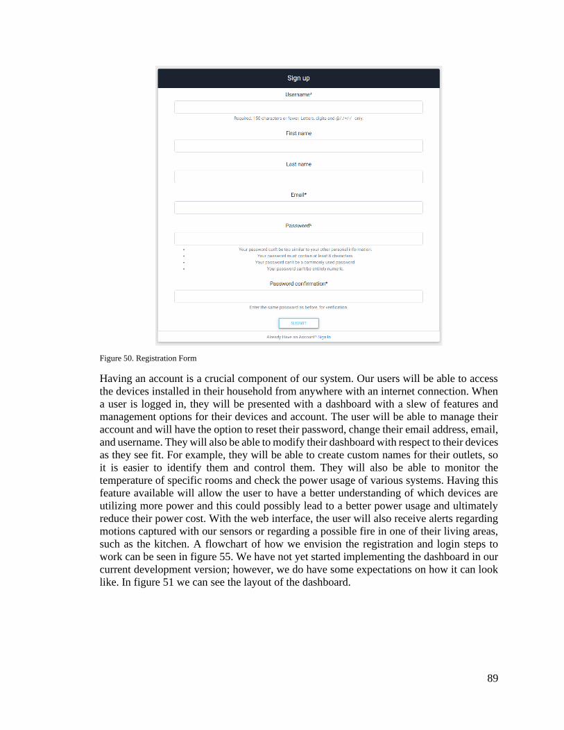
89
Figure 50. Registration Form
Having an account is a crucial component of our system. Our users will be able to access
the devices installed in their household from anywhere with an internet connection. When
a user is logged in, they will be presented with a dashboard with a slew of features and
management options for their devices and account. The user will be able to manage their
account and will have the option to reset their password, change their email address, email,
and username. They will also be able to modify their dashboard with respect to their devices
as they see fit. For example, they will be able to create custom names for their outlets, so
it is easier to identify them and control them. They will also be able to monitor the
temperature of specific rooms and check the power usage of various systems. Having this
feature available will allow the user to have a better understanding of which devices are
utilizing more power and this could possibly lead to a better power usage and ultimately
reduce their power cost. With the web interface, the user will also receive alerts regarding
motions captured with our sensors or regarding a possible fire in one of their living areas,
such as the kitchen. A flowchart of how we envision the registration and login steps to
work can be seen in figure 55. We have not yet started implementing the dashboard in our
current development version; however, we do have some expectations on how it can look
like. In figure 51 we can see the layout of the dashboard.

90
Figure 51. Dashboard Overview Example
The user will also be able to view and edit their profile information provided during
registration. In figure 52 we have an example of how such information will be shown to
our users.
Figure 52. Profile Information

91
Figure 53 shows the interface for editing a user profile.
Figure 53. Profile Editing
As we have previously mentioned, we will also allow the user to control their devices
through the dashboard. One of the features of our system will be the ability to control
outlets throughout the household. For example, if a user will not be at home during a certain
time frame, they could access their dashboard and would be presented with a simple
interface, as shown in figure 54, and deactivate a specific outlet in order to save energy.
Figure 54. Example of Outlet Control
As observed in the figure above, we will provide the user with an easy-to-use interface
where all the information they need for the device is readily available in a single screen.
We believe that in this way we can facilitate the usage of our system and optimize the time
of our users.

92
Figure 55. Registration and Login Flowchart
Another feature that will be implemented for the account management portion of our
system is the option for a user to recover their password in case they have forgotten or lost
it. The user will be guided through a series of steps which involves them confirming their
identity, providing us with their registered email and then receiving a confirmation email
where they will be able to reset their password. On figure 56 a flowchart shows how this
process will work.

93
Figure 56. Password Reset Flowchart
5.3.11. Database Schema Overview
In order for the system to work properly, we have to store the user information. As we have
discussed previously in Section 3.2.7, we are utilizing in our system a MySQL database.
This database will store many values that are connected to a specific user and to a specific
device in such user household. A tentative database schema is presented in figure 59. Also,
in table 22 we can see the current schema for the functionalities already implemented.

94
Table 22 Current Database Schema
Table Name
auth_group
auth_group_permissions
auth_user
auth_user_groups
auth_user_user_permissions
django_admin_log
django_content_type
django_migrations
django_session
If we take a closer look at one of these tables, we can see which kind of information we are
storing. For example, the information stored in table auth_user can be seen in figure 57.
Figure 57. Example of User Information in Database
Figure 58. Example of User Information Stored with MongoDB
As seen in figure 58, we have most of the same fields as the ones described in section 5.2.4,
when the user created their account and as well as extra fields that can be access by the
user dashboard, and also fields that are only accessible by the system administrator, in this
case, we the developers. Also, we can see in figure 58 that if we were to use MongoDB as
our database system the organization would be a little bit different, namely in a bson format
instead of a table format, however the functionality would be the same. It is important to
notice that even when accessing the user information through the database visualization
application, a user’s password is hashed to prevent unauthorized access. This is a feature
of our back-end framework of choice, Django.

95
Figure 59. Tentative Database Schema
5.4. Optical Design Details
We are utilizing a silicon photodiode for the fire detection circuit because it is cost
effective. The sensor can detect emissions in the 0.7-1.1µm wavelength range which is near
infrared and a small portion of the blackbody spectrum of fire. An InGaAs photodiode may
be more effective at fire detection because it can detect up to 1.7µm wavelength and this is
closer to the peak of fire’s blackbody spectrum, but an InGaAs photodiode is much more
expensive than silicon photodiode, so we opted to use the Silicon photodiode, shown in
figure 60.
Figure 60. Silicon Photodiode with Circuit Board
Source: https://ebay.to/2S0hTiS

96
We have chosen to utilize a single lens system to increase the detection range of the
photodiode as well as its field of view. The diode is only about 3mm in diameter allowing
only a very small amount of incident power to be absorbed. The lens we have chosen is
about half an inch and it will focus about four times the amount of incident radiation onto
the center of the diode. The single les system is housed in a small aluminum box due to
aluminum’s high reflectivity for infrared waves. This will allow any incident radiation that
wasn’t completely focused onto the diode to be reflected back onto it.
We are considering utilizing a band-pass filter with peak wavelength around 940
nanometers due to the sun’s transmission spectrum through the atmosphere. Water vapor
absorbs a large portion of radiation around 940 nanometers, so even though it is relatively
close to the peak of the blackbody spectrum for the sun not much is transmitted through
the atmosphere. This would mean there is less environmental noise at this wavelength, so
we could increase the signal to noise ratio of the photodiode system and decrease the
amount of false detections.
We are still exploring options for the mounting of our PIR photodiode, but we plan to use
something simple and able to be mounted to a wall. We looked through two separate
options for our motion detector and decided on the one depicted in Figure 61. We chose
this photodiode because of the superior field of view and proximity.
Figure 62. Passive Infrared Photodiode
Source: https://ebay.to/2xxyXDt and https://ebay.to/2XtAgCX
We’ve chosen to use a N-BK7 lens for our fire detector module with a focal length of 25.4
millimeters. We will position the photodiode directly behind the focal length at about 26.9
millimeters away from the lens to capture more light from flames. The following
calculations were made to find optimal sensor positioning for the best field of view and
most incident radiation. We used a maximum sensor range of 2 feet to allow optimal short-
range results.
1
𝑠+
1
𝑠′=
1
𝑓
Equation 5.3.1 Gaussian Lens Equation
Figure 61. Passive Infrared
Photodiode

97
1
𝑥+
1
24=
1
1
𝑥 = 1.043 𝑖𝑛𝑐ℎ𝑒𝑠 = 26.9 𝑚𝑖𝑙𝑙𝑖𝑚𝑒𝑡𝑒𝑟𝑠
5.5. Final Optics Specifications
5.5.1. Fire Hazard Detection Unit
The fire detector was able to detect both an open burner on a stovetop above 250 degrees
Fahrenheit as well as a small lighter flame from over two feet away. The largest
measurement that we had for our flame detection unit was 30 inches, but it would
consistently see the flame at two feet away so we decided to go with that number for the
range for reliability. The unit was unable to distinguish the flame from the open burner so
we changed it to a ‘Fire Hazard Detection Unit’ because it would detect fire hazards as
well as fire itself. The unit wouldn’t detect a burner covered by a pot or pan so there were
no issues with cooking regularly underneath the unit. The final angle of detection for the
unit was 16 degrees which is about 3.5 inches at a foot away. Hypothetically the unit can
detect larger flames from much further than 2 feet away, but since we didn’t have any way
to safely test this we didn’t add any specification for it.
5.5.2. Motion Sensor
The PIR sensor we chose was able to detect movement from up to five meters away. The
detection range was 120 degrees and the reset time was about five seconds. This unit was
relatively easy to install and performed as expected.
6. Prototype Testing
In the following sections we will discuss in detail how we have planned the testing portion
for our project. These sections will be separated in both Hardware and Software testing.
6.1. Hardware Testing
The following test plans will be used to test the functionality of each component of the
units we are building, this will ensure that the hardware is working properly prior to, and
after assembly. By ensuring the hardware is functional we can deduce that bugs that occur
in further testing will be more likely software issues which will be far easier to fix than
hardware malfunctions. Each table is designed to be a printable form that the engineer
assembling the product can use for Quality Assurance of the Unit.
6.1.1. AC Thermostat Testing Plan
Table 23 AC Thermostat Hardware Component Testing Plan
Product
Name
Component
Name
Test Type Testing Instructions
(Using all Safety
Precautions)
Expected
Results Pass
/Fail
AC System
Controller
Power Supply Power On Using a modified AC
cord connect the input
terminals of the power
supply with the Hot
Multimeter reads
24V at Output
Terminals (10%

98
wire in the + terminal
and the neutral wire in
the - terminal and with
a digital multimeter
(DMM) ensure that
24V is measured at the
Output terminals
Deviation
Allowed)
Step Down
Voltage
Regulator
Power On With the power
Supply powered on,
connect the Voltage
Regulator's input
terminals to the Power
Supply's output
terminals. Using a
DMM, ensure that the
Output Terminals of
the Voltage Regulator
measure 5V.
Multimeter reads
5V at Output
Terminals (10%
Deviation
Allowed)
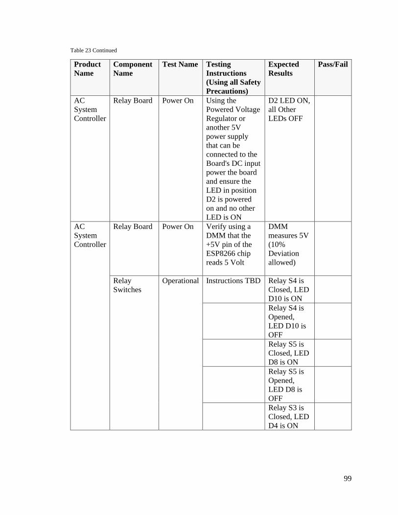
99
Table 23 Continued
Product
Name
Component
Name
Test Name Testing
Instructions
(Using all Safety
Precautions)
Expected
Results
Pass/Fail
AC
System
Controller
Relay Board
Power On Using the
Powered Voltage
Regulator or
another 5V
power supply
that can be
connected to the
Board's DC input
power the board
and ensure the
LED in position
D2 is powered
on and no other
LED is ON
D2 LED ON,
all Other
LEDs OFF
AC
System
Controller
Relay Board Power On Verify using a
DMM that the
+5V pin of the
ESP8266 chip
reads 5 Volt
DMM
measures 5V
(10%
Deviation
allowed)
Relay
Switches
Operational Instructions TBD Relay S4 is
Closed, LED
D10 is ON
Relay S4 is
Opened,
LED D10 is
OFF
Relay S5 is
Closed, LED
D8 is ON
Relay S5 is
Opened,
LED D8 is
OFF
Relay S3 is
Closed, LED
D4 is ON

100
Table 23 Continued
Product
Name
Component
Name
Test Name Testing
Instructions
(Using all Safety
Precautions)
Expected
Results
Pass/
Fail
AC
Controller
System
Relay
Switches
Operational Instructions are
TBD
Relay S3 is
Opened, LED
D4 is OFF
Relay S2 is
Closed, LED
D3 is ON
Relay S2 is
Opened, LED
D3 is OFF
Temperature
Sensor
Operational Instructions TBD Digital
Output from
Sensor reads
the measured
room
temperature
(5%
Deviation
Allowed)
AC System
Controller
(Assembled)
System Logical Terminal Logic
Instructions TBD
Red Terminal
Measures
24V
+-10%
Green
Terminal
Measures
24V
+-10%
Yellow
Terminal
Measures
24V
+-10%
White
Terminal
Measures
24V
+-10%
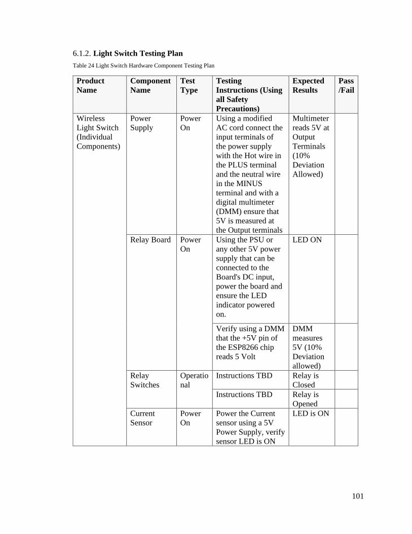
101
6.1.2. Light Switch Testing Plan
Table 24 Light Switch Hardware Component Testing Plan
Product
Name
Component
Name
Test
Type
Testing
Instructions (Using
all Safety
Precautions)
Expected
Results
Pass
/Fail
Wireless
Light Switch
(Individual
Components)
Power
Supply
Power
On
Using a modified
AC cord connect the
input terminals of
the power supply
with the Hot wire in
the PLUS terminal
and the neutral wire
in the MINUS
terminal and with a
digital multimeter
(DMM) ensure that
5V is measured at
the Output terminals
Multimeter
reads 5V at
Output
Terminals
(10%
Deviation
Allowed)
Relay Board Power
On
Using the PSU or
any other 5V power
supply that can be
connected to the
Board's DC input,
power the board and
ensure the LED
indicator powered
on.
LED ON
Verify using a DMM
that the +5V pin of
the ESP8266 chip
reads 5 Volt
DMM
measures
5V (10%
Deviation
allowed)
Relay
Switches
Operatio
nal
Instructions TBD Relay is
Closed
Instructions TBD Relay is
Opened
Current
Sensor
Power
On
Power the Current
sensor using a 5V
Power Supply, verify
sensor LED is ON
LED is ON
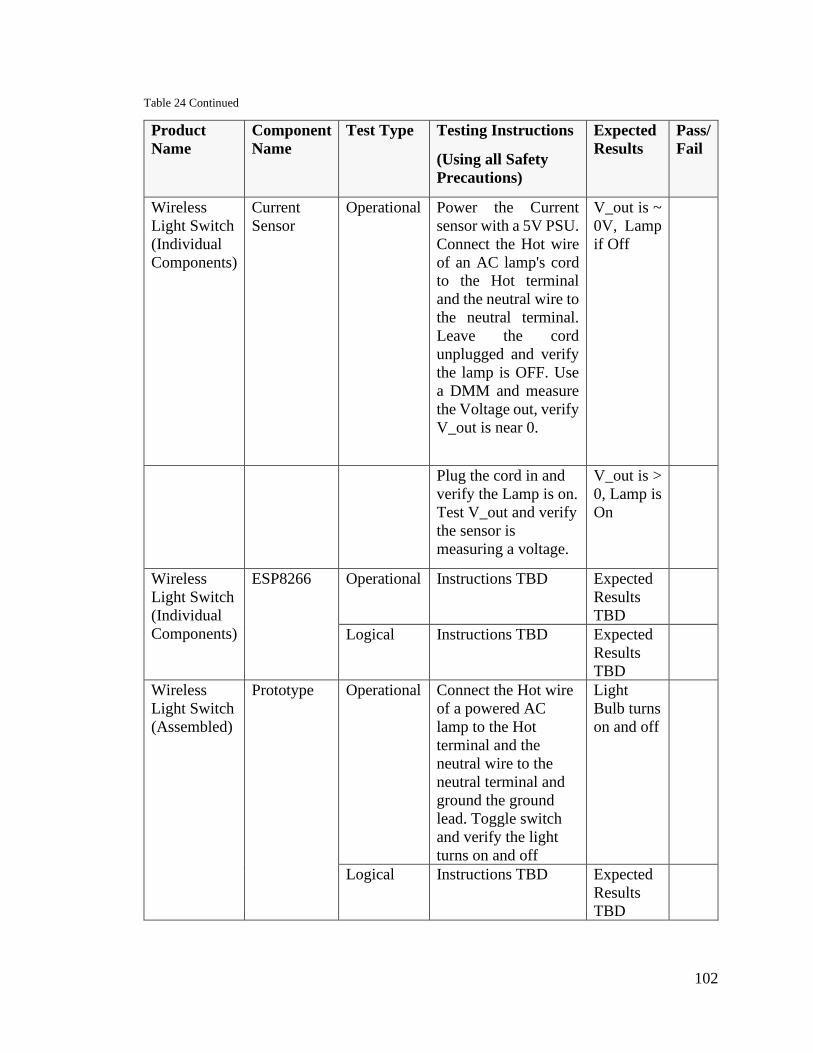
102
Table 24 Continued
Product
Name
Component
Name
Test Type Testing Instructions
(Using all Safety
Precautions)
Expected
Results
Pass/
Fail
Wireless
Light Switch
(Individual
Components)
Current
Sensor
Operational Power the Current
sensor with a 5V PSU.
Connect the Hot wire
of an AC lamp's cord
to the Hot terminal
and the neutral wire to
the neutral terminal.
Leave the cord
unplugged and verify
the lamp is OFF. Use
a DMM and measure
the Voltage out, verify
V_out is near 0.
V_out is ~
0V, Lamp
if Off
Plug the cord in and
verify the Lamp is on.
Test V_out and verify
the sensor is
measuring a voltage.
V_out is >
0, Lamp is
On
Wireless
Light Switch
(Individual
Components)
ESP8266 Operational Instructions TBD Expected
Results
TBD
Logical Instructions TBD Expected
Results
TBD
Wireless
Light Switch
(Assembled)
Prototype Operational Connect the Hot wire
of a powered AC
lamp to the Hot
terminal and the
neutral wire to the
neutral terminal and
ground the ground
lead. Toggle switch
and verify the light
turns on and off
Light
Bulb turns
on and off
Logical Instructions TBD Expected
Results
TBD

103
6.1.3. Smart Outlet Test Plan
Table 25 Outlet Hardware Component Testing Plan
Product
Name Componen
t Name Test Type Testing Instructions
(Using all Safety
Precautions)
Expected
Results Pass/
Fail
Wireless
Smart Outlet (Component
s)
Power
Supply Power On Using a modified AC cord
connect the input terminals
of the power supply with
the Hot wire in the PLUS
terminal and the neutral
wire in the MINUS
terminal and with a digital
multimeter (DMM) ensure
that 5V is measured at the
Output terminals
Multimete
r reads 5V
at Output
Terminals
(10%
Deviation
Allowed)
Relay
Board Power On Using the PSU or any other
5V power supply that can
be connected to the Board's
DC input, power the board
and ensure the LED
indicator powered on.
LED On
Verify using a DMM that
the +5V pin of the
ESP8266 chip reads 5 Volt
DMM
measures
5V (10%
Deviation
allowed)
Relay
Switches
Operation
al
Instructions TBD Relay is
Closed
Instructions TBD Relay is
Opened
Current
Sensor Power On Power The Current sensor
using a 5V Power Supply,
verify sensor LED is ON
LED is
ON
Operation
al
Power the Current sensor
with a 5V PSU. Connect
the the Hot wire of an AC
lamp's cord to the Hot
terminal and the neutral
wire to the neutral
termina.Leave the cord
unplugged and verify the
lamp is OFF. Use a DMM
and measure the Voltage
out, verify V_out is near 0.
V_out is ~
0V, Lamp
if Off
Plug the cord in and verify
the Lamp is on. Test V_out
and verify the sensor is
measuring a voltage.
V_out is >
0, Lamp is
On

104
Table 25 Continued
Product
Name
Component
Name
Test Type Testing
Instructions (Using
all Safety
Precautions)
Expected
Results
Pass/
Fail
Wireless
Smart Outlet (Components)
ESP8266 Operational Instructions TBD
Expected
Results TBD
Logical Instructions TBD Expected
Results TBD
Wireless
Smart Outlet (Assembled)
Prototype
Outlet is
Off at end
of
scheduled
time
Operational With Relay in On
position. Install the
Wall Outlet. Plug in
any device that
requires less than
15A and ensure
device is
operational
Relay is On,
Plugged in
device is On
Logical Energy Monitoring
instructions TBD Web
Application
present record
of current
measurements
Switching
Instructions TBD Web
Application
displays Outlet
is On,
Plugged-In
Device is OFF
Web
Application
displays Outlet
is Off,
Plugged-In
device is Off
Scheduling
Instructions TBD Outlet is On at
scheduled time
6.2. Software Testing
An essential step in any project is the testing portion. Because we want our project to be
pleasant to use by our end-users, we have dedicated large amounts of time in this phase.
Also, because we are offering a web application, we need our product to conform with
certain standards of the industry. Such standards were discussed in Section 4.1. Similarly,
testing standards also exist, and they were followed during the tests performed by us.

105
The testing plan for our project will encompass three primary stages: Unit Testing,
Integration Testing, and System Testing. This will help to ensure that potential issues at
every level of development are caught and weeded out in a timely manner and assist in the
process of isolating the exact nature of software bugs, which in turn will save significant
time in diagnosing its cause and finding a solution. The specific testing plans for each
phase are outlined below and will be applied more or less identically across every major
software component of the system in question.
Unit testing will be carried out by writing and running written tests for major functions and
modules within a given software system. These tests will be automated and designed with
consideration for the listed design goals of that function or module. Though the process of
writing these tests will take time, there will be a net benefit of time saved once they are
implemented into the design process, as they will allow the functionality of individual
components of the software to be verified in a clear pass/fail manner. Once individual
functions and classes have been isolated, an exacting and clear-cut testing plan for each
component of a given piece of software will be created and used as a baseline for the
writing of unit tests and the evaluation of their results. Once unit testing has been verified
to produce adequate results, integration testing can be carried out.
The purpose of integration testing is to identify potential faults in the interactions between
individual units. Although each unit may function properly on its own, unforeseen issues
may arise from the communication between those individual units. To that end, carrying
out integration testing helps to identify these issues by ensuring that the units are not only
tested in a vacuum, but also tested together. Integration testing need only be carried out
between units which are directly related to one another, I.E. two functions or classes which
are dependent on and communicate with one another during regular operation of the
software. Once integration testing is complete, system testing will be carried out.
Carrying out system testing will work to ensure that the given pieces of software, as a
whole, carry out their proper functions, and will endeavor to find and isolate issues which
arise at the highest level of integration between all the myriad components of the system
itself. System testing, in this context, will also server to verify that the interconnectivity
between the various pieces of software which make up the smart home system as a whole
is functioning properly, whether that happens to be the connection between the central hub
and the server or the connection between the various modules which make up the in-home
component of the system and the hub itself.
The structure of this testing plan outlines why it is important for rapid-prototyping to occur
at some point during the development stages, as interconnectivity is only tested at the
highest level of testing when it comes to the verification of the functionality of the final
product. The viability of the networking scheme and other related interconnectivity must
be verified at the earlier stages of development with proof-of-concept prototypes so as to
ensure that any potential incompatibilities between separate pieces of hardware are
identified early and that proper workarounds or replacements can be devised.
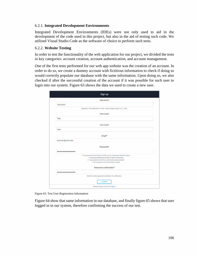
106
6.2.1. Integrated Development Environments
Integrated Development Environments (IDEs) were not only used to aid in the
development of the code used in this project, but also in the aid of testing such code. We
utilized Visual Studio Code as the software of choice to perform such tests.
6.2.2. Website Testing
In order to test the functionality of the web application for our project, we divided the tests
in key categories: account creation, account authentication, and account management.
One of the first tests performed for our web app website was the creation of an account. In
order to do so, we create a dummy account with fictitious information to check if doing so
would correctly populate our database with the same information. Upon doing so, we also
checked if after the successful creation of the account if it was possible for such user to
login into our system. Figure 63 shows the data we used to create a new user.
Figure 63. Test User Registration Information
Figure 64 show that same information in our database, and finally figure 65 shows that user
logged in in our system, therefore confirming the success of our test.

107
Figure 64. Test User Information in Database
Figure 65. Confirmation of Test User Log In
Another test that can also be performed is the password reset test. On figure x we can see
the flowchart of the actions the user needs to take in order to receive a new password in
case the old one has been lost or forgotten. This feature is implemented in the web app and
the following figures demonstrate the process with the information of a test user, the same
one created in the previous test.
When the user navigates to the login page, they have the option to click the “forgot
password” link. The user will then be redirected to a form where they can input the email,
as seen in figure 66, registered to their account.
Figure 66. First Step for Password Reset
After successful verification of the associated registered user email address, a success
message is displayed directing the user to check their email box, as seen in figure 67.
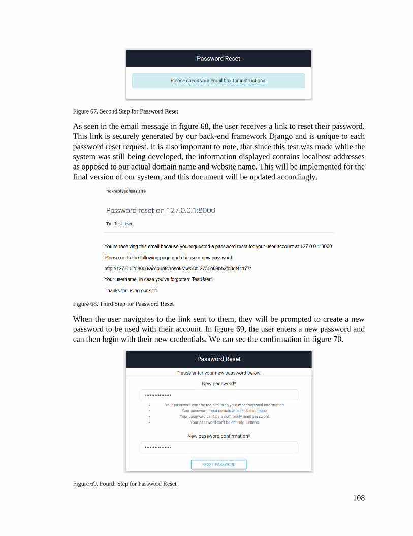
108
Figure 67. Second Step for Password Reset
As seen in the email message in figure 68, the user receives a link to reset their password.
This link is securely generated by our back-end framework Django and is unique to each
password reset request. It is also important to note, that since this test was made while the
system was still being developed, the information displayed contains localhost addresses
as opposed to our actual domain name and website name. This will be implemented for the
final version of our system, and this document will be updated accordingly.
Figure 68. Third Step for Password Reset
When the user navigates to the link sent to them, they will be prompted to create a new
password to be used with their account. In figure 69, the user enters a new password and
can then login with their new credentials. We can see the confirmation in figure 70.
Figure 69. Fourth Step for Password Reset

109
Figure 70. Fifth Step for Password Reset
If the user tries to login with their new credentials, they will be able to successfully do so,
as seen in figure 71.
Figure 71. Successful Login After Password Reset
With the steps described above, the user is able to successfully reset their password in case
it is lost or forgotten. The system behind the process described is discussed in Section 5.2.4.
6.3. Optics and Sensor Testing
The silicon infrared photodiode for fire detection was tested at varying distances and with
a lens. Our first procedure was to attach a 5-volt power supply to the diode circuit and a
multi-meter to the DC output. A lighter flame was put in front of the diode at one-foot
intervals up to five feet. This was repeated with the N-BK7 lens present in front of the
diode. The entire experiment was repeated using a propane torch instead of a lighter to
simulate a larger flame. All output voltages were recorded.
Table 26 Small Flame Detection
Distance
(Inches)
Lens Not Present (Output
Voltage Abs. Value)
Lens Present
3 0V 0V
6 0V 0V
9 0V 0V
12 0V 0V
15 0V 0V
18 0V 0V
21 0V 0V
24 0V 0V
27 5V 0V
30 5V 0V
33 5V 5V
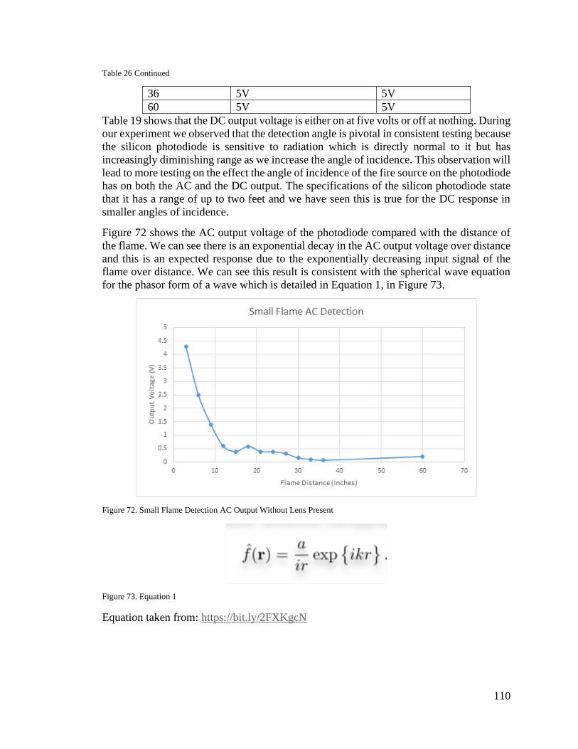
110
Table 26 Continued
36 5V 5V
60 5V 5V
Table 19 shows that the DC output voltage is either on at five volts or off at nothing. During
our experiment we observed that the detection angle is pivotal in consistent testing because
the silicon photodiode is sensitive to radiation which is directly normal to it but has
increasingly diminishing range as we increase the angle of incidence. This observation will
lead to more testing on the effect the angle of incidence of the fire source on the photodiode
has on both the AC and the DC output. The specifications of the silicon photodiode state
that it has a range of up to two feet and we have seen this is true for the DC response in
smaller angles of incidence.
Figure 72 shows the AC output voltage of the photodiode compared with the distance of
the flame. We can see there is an exponential decay in the AC output voltage over distance
and this is an expected response due to the exponentially decreasing input signal of the
flame over distance. We can see this result is consistent with the spherical wave equation
for the phasor form of a wave which is detailed in Equation 1, in Figure 73.
Figure 72. Small Flame Detection AC Output Without Lens Present
Figure 73. Equation 1
Equation taken from: https://bit.ly/2FXKgcN

111
Table 27 Large Flame Detection DC Output
Distance
(Inches)
Lens Not Present
(Output Voltage)
Lens Present
3 5V 5V
6 5V 5V
9 5V 5V
12 5V 5V
15 5V 5V
18 5V 5V
21 5V 5V
24 5V 5V
27 5V 5V
30 5V 5V
33 5V 5V
36 5V 5V
60 5V 5V
The NIR photodiode also has an AC output that we may utilize along with software to
trigger positive outputs. An oscilloscope was attached to the NIR photodiode’s AC output
and the previous test was performed with the diode. The following waveforms were
observed from the AC and DC outputs:
Figure 74. NIR Sensor DC Response Rise/Fall Time
Figure 74 shows the DC response of the NIR sensor taken at three inches. We observe the
negative five-volt output when the flame is initially sparked and a decay as the flame is
kept. A positive five-volt output was recorded when the flame was put out. The figure
shows the rise and fall times of the DC output to be approximately 260 milliseconds. This
is the standard response to any fires directly within the center of the sensor’s field of view.
We’ve observed that the sensor is highly sensitive to the detection angle and that angles
over twenty degrees can lower the input signal drastically and even cause the sensor to not
detect the fire. Fires on the edge of the sensor’s field of view will give a DC output that
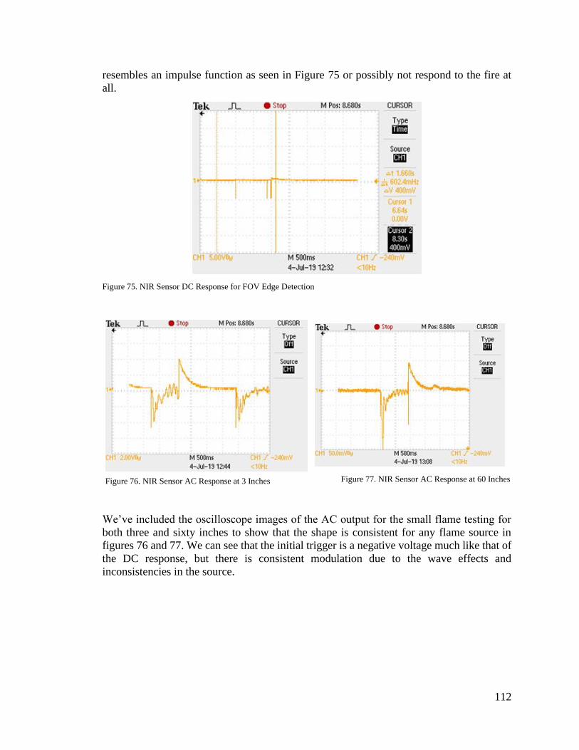
112
resembles an impulse function as seen in Figure 75 or possibly not respond to the fire at
all.
Figure 75. NIR Sensor DC Response for FOV Edge Detection
We’ve included the oscilloscope images of the AC output for the small flame testing for
both three and sixty inches to show that the shape is consistent for any flame source in
figures 76 and 77. We can see that the initial trigger is a negative voltage much like that of
the DC response, but there is consistent modulation due to the wave effects and
inconsistencies in the source.
Figure 76. NIR Sensor AC Response at 3 Inches Figure 77. NIR Sensor AC Response at 60 Inches
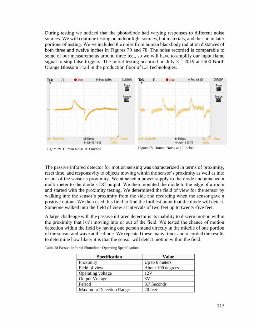
113
During testing we noticed that the photodiode had varying responses to different noise
sources. We will continue testing on indoor light sources, hot materials, and the sun in later
portions of testing. We’ve included the noise from human blackbody radiation distances of
both three and twelve inches in Figures 79 and 78. The noise recorded is comparable to
some of our measurements around three feet, so we will have to amplify our input flame
signal to stop false triggers. The initial testing occurred on July 3rd, 2019 at 2500 North
Orange Blossom Trail in the production floor of L3 Technologies.
The passive infrared detector for motion sensing was characterized in terms of proximity,
reset time, and responsivity to objects moving within the sensor’s proximity as well as into
or out of the sensor’s proximity. We attached a power supply to the diode and attached a
multi-meter to the diode’s DC output. We then mounted the diode to the edge of a room
and started with the proximity testing. We determined the field of view for the sensor by
walking into the sensor’s proximity from the side and recording when the sensor gave a
positive output. We then used this field to find the furthest point that the diode will detect.
Someone walked into the field of view at intervals of two feet up to twenty-five feet.
A large challenge with the passive infrared detector is its inability to discern motion within
the proximity that isn’t moving into or out of the field. We tested the chance of motion
detection within the field by having one person stand directly in the middle of one portion
of the sensor and wave at the diode. We repeated these many times and recorded the results
to determine how likely it is that the sensor will detect motion within the field.
Table 28 Passive Infrared Photodiode Operating Specifications
Specification Value
Proximity Up to 6 meters
Field of view About 100 degrees
Operating voltage 12V
Output Voltage 3V
Period 8.7 Seconds
Maximum Detection Range 20 feet
Figure 79. Human Noise at 3 Inches Figure 78. Human Noise at 12 Inches

114
We measured the actual blockade time for the PIR photodiode by consistently moving
within the field of view and taking the difference between the first two triggers. We can
see from Figure 80 that the period is 8.7 seconds and the initial trigger voltage is a positive
3.7V output.
Figure 80. PIR Output for Consistent Triggering Measuring Period
We will continue with testing of the PIR sensors for field of view and small motion
detection. The field of view test will be simple: one of us will move into the sensor’s center
of field and then he will move outward by one-foot intervals and we will find where the
sensor no longer sees him. We will then repeat the test by moving backwards a few feet
and repeating measurements. This will help us characterize the sensor’s field of view.
The NIR sensors will need to be tested with a larger flame and a lens present. We will also
test the NIR sensors for field of view and false detections. The false detection testing will
use several different noise sources to trigger false detection on both the AC and DC outputs
of the sensor. We will start with our main noise source: the sun. The sensor will be covered
by a box and then it will be suddenly exposed to sunlight as the box is removed. This will
show us if our product can be used in the sun or by windows. Our next noise source we
will use is a flickering lamp. We will put our sensor within a foot of a lamp and repeatedly
turn it on and off to try to trigger false detections through house lighting.
6.3.1. Secondary Sensor Testing
After initial testing was concluded with both the PIR and NIR sensors being tested for
output signals and basic functionalities. Further testing was conducted in a private domicile
at 3805 Stonefield Drive for noise sources, potentiometer tuning, and different input
voltage levels. The lens and full system testing will be conducted in the final section. We
recognized that the sun could pose a potential threat to our fire detection system due to its
blackbody spectrum overlapping our NIR sensor’s spectrum, so we decided to design a test
to see if the sun is capable of causing false triggers. We set up our oscilloscope, NIR
photodiode, and power supply by a window with a curtain and we moved the curtain to
allow the sunlight to be incident to the photodiode. We did this for both the AC and DC
outputs. Figure 81 shows the AC response of the photodiode. We can see that there is a
trigger which will cause issues if we are going to use the AC output. The DC response for
the NIR photodiode was consistent and offered no triggers for any amount of sunlight.

115
There are a few options to deal with this issue: We can utilize a bandpass filter to only
allow light around 940nm in which is absorbed in the atmosphere, we can place the sensors
away from any windows or out of direct line of sight of the sun, or we can use the DC
response for our project to stop any false triggers.
Figure 81. AC Response to the Sun
Once we tested to see if the sun was a noise source of interest we quickly realized that our
lighting system could pose possible challenges to the fire detection system, so we tested to
see the effect an incident 60-Watt lightbulb had on the AC and DC responses of the NIR
photodiode. Figure 82 shows the AC response of the NIR photodiode when we turned on
a light directly 3 inches above it. We can see that there is an instantaneous trigger and the
signal changes by over a full volt. This poses yet another challenge for our fire detector
because this means that the indoor lighting could affect the trigger times of the fire detector
if we use an AC response. Using a filter could help solve this issue as well as pointing the
detector downward to avoid incident ambient light getting onto the photodiode and causing
it to give off a false trigger to the system. There was no DC response to the light flickering
so using the DC output may be the best solution for now.
Figure 82. AC Response to Light source

116
We looked at our waveforms from the initial testing and realized that the potentiometers
weren’t being correctly tuned for optimal testing results due to the output waveforms. We
adjusted the potentiometers on our units, and we were able to refine the resulting
waveforms into more consistent voltages. We also found that the sensors gave a much
better response time after tuning the potentiometers. Figure 83 shows a DC response of the
NIR sensor to a regular fire. The figure shows a remarkably uniform square wave which is
exceedingly easy for any central control system to identify and respond to.
Figure 83. DC Response of NIR Sensor with Tuned Potentiometer
The large flame testing was completed, and it held surprising results compared with what
we had originally imagined. We predicted that the larger propane torch flame would allow
the NIR photodiode to detect it from much further away due to the higher heat and size of
the flame. We’ve found out that the propane torch doesn’t trigger the sensor at all. We
think this may be because the flame is more directed due to the compressed nature of the
propane tank torch or even due to the unique burning properties of propane. This has little
effect on the actual effectiveness of our fire detector because we’re trying to detect
uncontrolled fires and propane torches are controlled.
The propane torch experiment made us consider the possibility of a hot object triggering a
response from our NIR photodiodes, so we decided to design an experiment to measure the
AC and DC responses of the photodiodes from hot sources. We heated a piece of quarts to
over 1,000 degrees Fahrenheit and then moved it in front of our sensor for analysis. Figures
84 and 85 show the AC and DC responses for the heated quarts and both show that the
sensor triggered. The AC response was detectable from half a foot away and the DC
response was from just a few inches, so the DC response has a higher trigger threshold.
This means the sensors can see when something is exceedingly hot, so this adds to the
safety of the device.
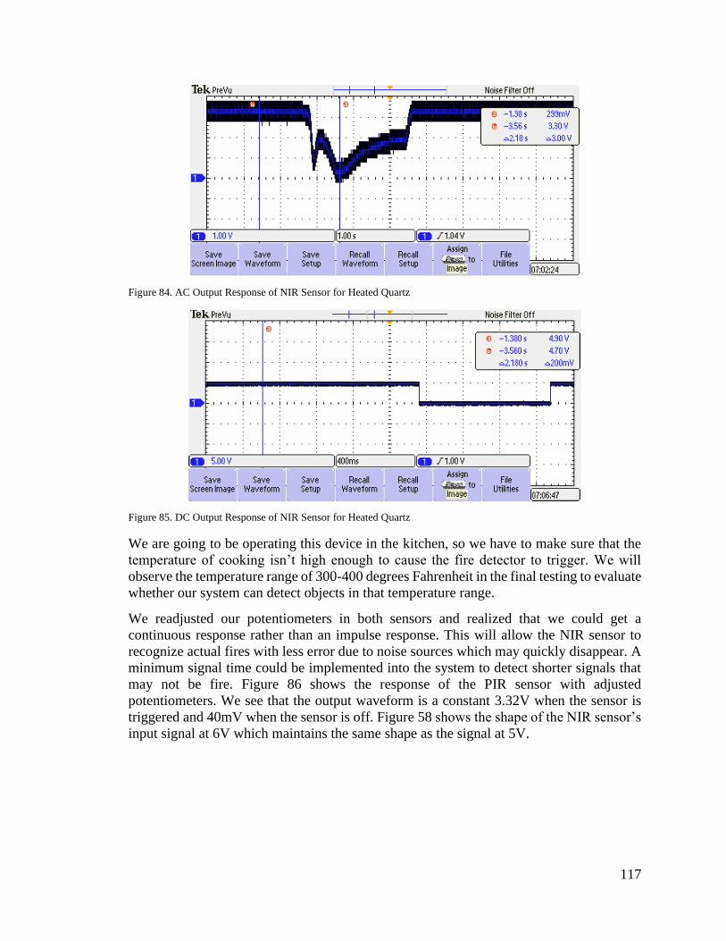
117
Figure 84. AC Output Response of NIR Sensor for Heated Quartz
Figure 85. DC Output Response of NIR Sensor for Heated Quartz
We are going to be operating this device in the kitchen, so we have to make sure that the
temperature of cooking isn’t high enough to cause the fire detector to trigger. We will
observe the temperature range of 300-400 degrees Fahrenheit in the final testing to evaluate
whether our system can detect objects in that temperature range.
We readjusted our potentiometers in both sensors and realized that we could get a
continuous response rather than an impulse response. This will allow the NIR sensor to
recognize actual fires with less error due to noise sources which may quickly disappear. A
minimum signal time could be implemented into the system to detect shorter signals that
may not be fire. Figure 86 shows the response of the PIR sensor with adjusted
potentiometers. We see that the output waveform is a constant 3.32V when the sensor is
triggered and 40mV when the sensor is off. Figure 58 shows the shape of the NIR sensor’s
input signal at 6V which maintains the same shape as the signal at 5V.
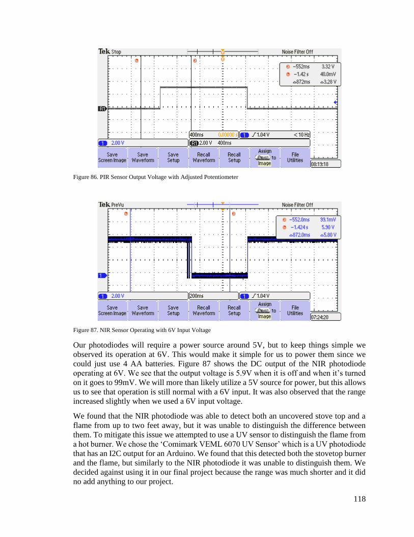
118
Figure 86. PIR Sensor Output Voltage with Adjusted Potentiometer
Figure 87. NIR Sensor Operating with 6V Input Voltage
Our photodiodes will require a power source around 5V, but to keep things simple we
observed its operation at 6V. This would make it simple for us to power them since we
could just use 4 AA batteries. Figure 87 shows the DC output of the NIR photodiode
operating at 6V. We see that the output voltage is 5.9V when it is off and when it’s turned
on it goes to 99mV. We will more than likely utilize a 5V source for power, but this allows
us to see that operation is still normal with a 6V input. It was also observed that the range
increased slightly when we used a 6V input voltage.
We found that the NIR photodiode was able to detect both an uncovered stove top and a
flame from up to two feet away, but it was unable to distinguish the difference between
them. To mitigate this issue we attempted to use a UV sensor to distinguish the flame from
a hot burner. We chose the ‘Comimark VEML 6070 UV Sensor’ which is a UV photodiode
that has an I2C output for an Arduino. We found that this detected both the stovetop burner
and the flame, but similarly to the NIR photodiode it was unable to distinguish them. We
decided against using it in our final project because the range was much shorter and it did
no add anything to our project.
119
7. User Manual
In the following sections we provide the user with instructions on how to use the main
features of our system.
7.1. Account Management
7.1.1. User Registration
When the user first sets up their system, they will need access to our web application. In
order to do so they will need a registered account with our system. To do so, the user can
take the following steps:
1. From a web browser, navigate to http://hsas.site
2. Click on “Web Application”
3. Click “Register” on the top navigation bar
4. Alternatively, the user can login with their social account
5. Fill out the form with their information
6. After submitting the form, the user will be automatically logged in
7.1.2. Profile Management
The user is also able to see and edit the information on their profile. This is useful in case
they need to update any information provided when registering into the system or checking
if the information is correct. Following the steps below the user will be able to do so.
1. From a web browser, navigate to http://hsas.site
2. Login into the system
3. On the top navigation bar, click “Account”
4. Then click “View Profile”
If the user wishes to edit the information on their profile. They can take the following steps:
1. Click “Edit Profile”
2. A screen with their current information is displayed
3. The user can now edit the fields with new information
4. Click “Save”
5. The user is redirected to the “View Profile” page with the updated information
7.1.3. Dependents
On the profile page, the user also has the ability to add dependents to their main account.
This feature serves the purpose of allowing other people to view and manage the devices
connected to the household. A use case for example, would be allowing another member
of the household to control the lights.
To add a dependent the user can follow these steps:
1. From the dashboard click “Account” at the top right of the page
2. Click “View Profile” from the dropdown menu

120
3. Next, click “Manage Dependents” from the Profile Page
4. The user is presented with the screen as seen in figure 88
5. From here they can add a new dependent by inserting their username or accept and
decline a request.
Figure 88. Management of Dependents
7.2. Dashboard
7.2.1. Devices
When the finishes creating their account, they will be redirected to the dashboard. This is
the main screen for our system. From here, they are able to add, edit, delete devices and
create tasks for them. To add a device the user will need to know the serial number of the
device they want to add and as well the location where the device will be. The following
steps can be taken to add a new outlet, a similar process to the other devices.
1. From the dashboard, click “Add New Outlet” button
2. The user is then presented with the form shown in figure 89
3. The user can then enter the serial number and location of where the outlet will be
installed
Figure 89. New Outlet Example

121
4. After doing so, the user will be redirected to the dashboard with the new light added.
The user is also able to edit the devices. For example, if the user wants to edit the location
of an outlet, they can follow these steps:
1. From the dashboard, click on the “Edit” button next to the device the user wants to
edit
2. The user will be presented with a screen similar to the one in figure 90
Figure 90. Edit Outlet Example
3. Once a new location is inserted the user can click the “Submit” button which will
then redirect them to the dashboard
As we can see from figure 90 as well, the user has the possibility to delete a device. The
following steps should be taken:
1. From the dashboard, click the “Edit” button for the device the user wants to edit
2. Click the “delete” button
3. The user is then presented with a confirmation dialog as shown if figure 91
Figure 91. Deleting a device

122
7.2.2. Motion Sensor
One of the devices available for our system, is a motion sensor. This will allow the user to
stay informed about any movement captured in the room where the user installed the
sensor. These changes are reflected on the dashboard and as well as an email notification.
At first installation, the motion sensor will display a status similar to the one shown in
figure 92. When motion is detected the status will change to the one depicted in figure 93,
and the user is also able to see the time the motion sensor was triggered.
Figure 92. Initial Status of Motion Sensor
Figure 93. Message when Motion Sensor is triggered

123
7.2.3. Fire Hazard Detector
Another device available for our system is a fire hazard detector. This device should ideally
be installed above the stovetop of the user’s kitchen. The device will trigger in a similar
manner as described for the motion sensor, and therefore the user will receive notification
both on the dashboard and on their registered email. The different status messages can be
seen in figures 94 and 95.
Figure 94. Initial Fire Hazard Detector Status
Figure 95. Message when Fire Hazard Detector is triggered

124
7.2.4. Tasks
Another feature of our system is the ability to create automated tasks for some of the
devices installed. The user for example, can create a task to turn on a light at a specific date
and time. To do so the user can follow these steps:
1. From the dashboard, the user should click “Tasks” at the top of the page
2. The user will then be presented with a screen that shows a list of the current created
tasks and as well a button to create a new one.
3. Once the user clicks the “Add New Task” button they can select which device they
can create the task for.
4. As seen in figure 96 the user can select the date and time that they want the task to
occur.
5. After submitting the form, the user will be redirected to the main tasks page, where
a message saying the tasks was successfully created is shown.
Figure 96. Example of Outlet Task creation
8. Future Improvements
This section will detail the technology that could be used to improve the quality of our
project if we had more resources such as money or time.
8.1. Fire Detection Improvements
Our fire detector currently consists of an infrared photodiode on an embedded circuit which
amplifies the output signal given by the diode for easy detection. We’ve demonstrated the
shortcomings of this sensor such as range, field of view, and false detections such as
sunlight or room lighting. This section will cover better detection methods than our current
photodiode can provide.
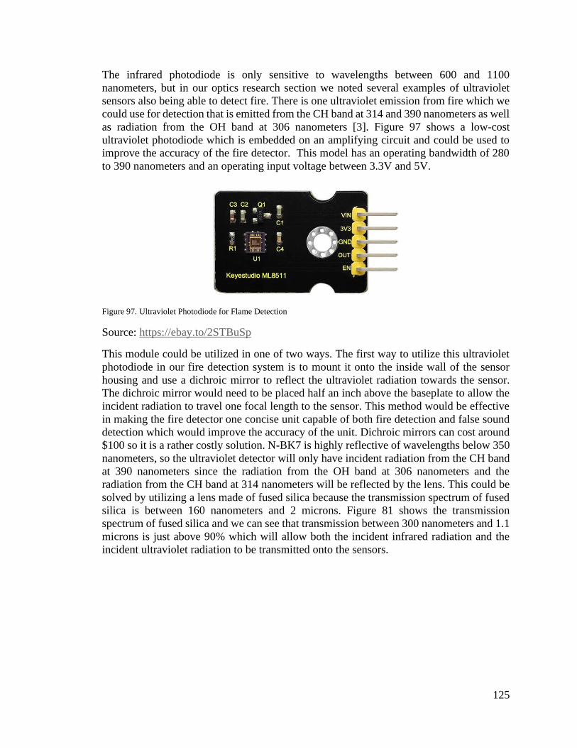
125
The infrared photodiode is only sensitive to wavelengths between 600 and 1100
nanometers, but in our optics research section we noted several examples of ultraviolet
sensors also being able to detect fire. There is one ultraviolet emission from fire which we
could use for detection that is emitted from the CH band at 314 and 390 nanometers as well
as radiation from the OH band at 306 nanometers [3]. Figure 97 shows a low-cost
ultraviolet photodiode which is embedded on an amplifying circuit and could be used to
improve the accuracy of the fire detector. This model has an operating bandwidth of 280
to 390 nanometers and an operating input voltage between 3.3V and 5V.
Figure 97. Ultraviolet Photodiode for Flame Detection
Source: https://ebay.to/2STBuSp
This module could be utilized in one of two ways. The first way to utilize this ultraviolet
photodiode in our fire detection system is to mount it onto the inside wall of the sensor
housing and use a dichroic mirror to reflect the ultraviolet radiation towards the sensor.
The dichroic mirror would need to be placed half an inch above the baseplate to allow the
incident radiation to travel one focal length to the sensor. This method would be effective
in making the fire detector one concise unit capable of both fire detection and false sound
detection which would improve the accuracy of the unit. Dichroic mirrors can cost around
$100 so it is a rather costly solution. N-BK7 is highly reflective of wavelengths below 350
nanometers, so the ultraviolet detector will only have incident radiation from the CH band
at 390 nanometers since the radiation from the OH band at 306 nanometers and the
radiation from the CH band at 314 nanometers will be reflected by the lens. This could be
solved by utilizing a lens made of fused silica because the transmission spectrum of fused
silica is between 160 nanometers and 2 microns. Figure 81 shows the transmission
spectrum of fused silica and we can see that transmission between 300 nanometers and 1.1
microns is just above 90% which will allow both the incident infrared radiation and the
incident ultraviolet radiation to be transmitted onto the sensors.

126
Figure 98. Transmission Spectrum of Fused Silica
Source: https://bit.ly/2YCBxHn
The second method of utilizing this module is by having two lenses beside each other on
one sensor housing with each focusing directly onto a sensor. This would allow radiation
from both the CH and OH bands to be transmitted onto the ultraviolet photodiode because
we could choose two separate lenses. This method would be much cheaper than the former
because only an extra lens would be added to the system. This type of system could fail to
detect fires if it occurs within the field of view of one photodiode but not in the other
photodiodes field of view. This is because both systems will be independent of each other
due to the incident radiation being different for both lenses.
The NIR photodiode cannot detect peak emissions of flame which occurs at 4.3 microns
due to the emission of carbon dioxide [3]. A more accurate device which is much more
expensive than an infrared photodiode is an infrared CCD camera. One particular CCD
camera which is praised as being relatively low cost can detect a large bandwidth which
begins in the ultraviolet spectrum at 250 nanometers and ends in the mid-infrared spectrum
at 12 microns. This makes the system extremely accurate because it can be triggered easily
by the 4.3 microns radiation and it can confirm whether the source was fire by correlating
it with the 390 nanometers emission from the CH band [3]. Not only does this allow the
system to have a large increase in both range and accuracy, but it also allows users to have
the choice of physically taking pictures and videos of the observed fire.
The fire detector could also be improved by utilizing a photodiode which is sensitive to
mid-wave infrared radiation along with our NIR photodiode. The model Lms49PD-05
series photodiode offered by lmsnt.com can detect mid-wave infrared radiation between
2.8 and 4.9 micrometers which contains both peak emissions at 4.3 microns from the CO2
emission and 2.7 microns from the H2O and CO2 emissions. Figure 9.1.1.3 shows the
typical spectral response of the Lms49PD-05 series to radiation within its operational
bandwidth. We can see that the photosensitivity is high for both our expected emission
peaks at 0.8 amperes per watt at 2.9 microns and about 1 ampere per watt at 4.3 microns.

127
Figure 99. Lms49PD-05 Series Spectral Response of Operational Bandwidth
Source: https://bit.ly/2K9F4oK
This type of photodiode is expensive and would also require a lens capable of transmitting
mid-wave infrared radiation with small losses. A sodium-chloride lens would be a good
candidate for this application because it will transmit radiation up to 10 microns with over
a 90% transmission rate. This type of lens is also relatively inexpensive.
9. Administrative Content
9.1. Milestone Discussion
We decided from the beginning of the semester that we’d meet every Thursday at seven
p.m. at the UCF library to discuss current progress and future goals. Table 29 details all of
our goals and milestones.
Table 29 Milestones
Milestone Completion
Date
First Group Meeting 5/13/2019
Brainstorm Ideas 5/19/2019
Decide on Idea 5/24/2019
Second Group Meeting 5/21/2019
Finish Divide and Conquer 5/27/2019
Meeting with Professor 5/28/2019
Third Group Meeting 5/30/2019
Finish Divide and Conquer 2.0 6/7/2019
Fourth Group Meeting 6/7/2019
Complete Table of Contents 6/9/2019
Fifth Group Meeting 6/13/2019
Initial Sensor Testing 7/3/2019

128
Table 29 Continued
Sixth Group Meeting 6/27/2019
Seventh Group Meeting 7/5/2019
Finish 50% Draft 7/7/2019
Eight Group Meeting 7/18/2019
Secondary Sensor Testing 7/19/2019
Ninth Group Meeting 7/25/2019
Order of Parts 9/1/2019
Sensors Testing 9/30/2019
Communication Testing 9/30/2019
Prototyping 10/13/2019
PCB Assembly 11/12/2019
Display Build 11/15/2019
9.2. Division of Responsibilities
Each member of the group will have an area of the project to be responsible for. However,
we all will contribute to each other’s work if needed and if help is requested. Some areas
also will function together and therefore we will work in this specific section at the same
time.
Table 30 Division of Responsibilities
Area Person Responsible
Sensors Avery Stevenson
Outlets, Smart Switch and AC Control Felix Henriquez
Communication between Devices Matthew Allen
Web Server / Database / User Interface Guilherme Costa

129
9.3. Budget Discussion
As of the date we are writing this document, our group does not have a sponsor. Therefore,
we are funding the project as a group. In this section we have provided a table to the reader
with the expenses we have planned for this project.
Table 31 Budget Allocation
Parts Expected Costs
Motion Sensor System $10
Thermal Sensor System $10
Micro Controllers $40
System Controller $40
PCB $30
Outlet System $30
Sensor Housing $35
Web Server $45
Domain $15
Total $295
130
Appendices
References
[1] “An Illustration of Making a Home Automation System Using Raspberry Pi and PIR
Sensor.” 2018 International Conference on Intelligent Circuits and Systems
(ICICS), Intelligent Circuits and Systems (ICICS), 2018 International Conference
on, ICICS, 2018, p. 439. EBSCOhost, doi:10.1109/ICICS.2018.00095.
[2] Gunawan, Teddy Surya1, [email protected]. m., et al. “Performance Evaluation of
Smart Home System Using Internet of Things.” International Journal of Electrical
& Computer Engineering (2088-8708), vol. 8, no. 1, Feb. 2018, pp. 400–
411. EBSCOhost, doi:10.11591/ijece.v8i1.pp400-411.
[3] Le Maoult, Y., et al. “Fire Detection: A New Approach Based on a Low Cost CCD
Camera in the Near Infrared.” Process Safety and Environmental Protection, vol. 85,
no. 3, Jan. 2007, pp. 193–206. EBSCOhost, doi:10.1205/psep06035.
[4] Chin-Chi Cheng, and Dasheng Lee. “Enabling Smart Air Conditioning by Sensor
Development: A Review.” Sensors (14248220), vol. 16, no. 12, Dec. 2016, p. 2028.
EBSCOhost,
search.ebscohost.com/login.aspx?direct=true&db=edb&AN=120375836&site=eds-
live&scope=site.
[5] Le Maoult, Y., et al. “Fire Detection: A New Approach Based on a Low Cost CCD
Camera in the Near Infrared.” Process Safety and Environmental Protection, vol. 85,
no. 3, Jan. 2007, pp. 193–206. EBSCOhost, doi:10.1205/psep06035.
[6] “Usage Statistics of Apache.” W3Techs, w3techs.com/technologies/details/ws-
apache/all/all.
[6] “Usage Statistics of Apache.” W3Techs, w3techs.com/technologies/details/ws-
apache/all/all.
[7] “Usage Statistics of Nginx.” W3Techs, w3techs.com/technologies/details/ws-
nginx/all/all.
[8] “Documentation.” Django, docs.djangoproject.com/en/2.2/howto/static-files/.
[9] “Brute Forcing Wi-Fi-Protected Setup”
https://sviehb.files.wordpress.com/2011/12/viehboeck_wps.pdf
[10] “Download Raspbian for Raspberry Pi”
https://www.raspberrypi.org/downloads/raspbian/
[11] https://www.raspberrypi.org/products/raspberry-pi-3-model-b-plus/

131
Copyright Permissions
For every image or code used in the project that was not of our own productions was
utilized with the required permission upon requests shown below.
Material Design Bootstrap Web Framework. As displayed on the website:
Copyright (c) 2019 MDBootstrap.com
THE SOFTWARE IS PROVIDED "AS IS", WITHOUT WARRANTY OF ANY
KIND, EXPRESS OR IMPLIED, INCLUDING BUT NOT LIMITED TO
THE WARRANTIES OF MERCHANTABILITY, FITNESS FOR A PARTICULAR
PURPOSE AND NONINFRINGEMENT. IN NO EVENT SHALL THE AUTHORS
OR
COPYRIGHT HOLDERS BE LIABLE FOR ANY CLAIM, DAMAGES OR OTHER
LIABILITY, WHETHER IN AN ACTION OF CONTRACT, TORT OR OTHERWISE,
ARISING FROM, OUT OF OR IN CONNECTION WITH THE SOFTWARE OR THE
USE OR OTHER DEALINGS IN THE SOFTWARE.