Home Entertainment Automation Using UPnP AV Architecture and
15
Home Entertainment Automation Using UPnP AV Architecture and Technology EDWARD F. STEINFELD, EMBEDDED COMPUTING MARKET CONSULTANT Use Network-Enabled AV Devices and UPnP Technology to Select What You Want to Play and Where You Want to Play it. Contents UPnP AV Overview ....................................................................................................................................... 2 Content Directory Service ........................................................................................................................ 3 Connection Manager Service .................................................................................................................. 4 AV Transport Service ............................................................................................................................... 4 Rendering Control .................................................................................................................................... 4 Media Renderer ............................................................................................................................................ 4 Media Server ................................................................................................................................................. 5 Media Control Point ....................................................................................................................................... 6 UPnP Overview ............................................................................................................................................. 7 UPnP Function Layers ............................................................................................................................. 8 Device Addressing Layer .................................................................................................................... 9 Device Discovery Layer ...................................................................................................................... 9 Device Description Layer .................................................................................................................... 9 Control Layer ...................................................................................................................................... 9 Event Messaging Layer ...................................................................................................................... 9 Presentation Layer ............................................................................................................................ 10 UPnP Device Architecture ................................................................................................................ 10 UPnP Forum Templates ................................................................................................................... 10 Vendor-Specific Layer ...................................................................................................................... 10 UPnP Standards .................................................................................................................................... 10 Conclusion................................................................................................................................................... 12 Author .......................................................................................................................................................... 12 Resources ................................................................................................................................................... 13
Transcript of Home Entertainment Automation Using UPnP AV Architecture and

Home Entertainment Automation Using
UPnP AV Architecture and Technology
EDWARD F. STEINFELD, EMBEDDED COMPUTING MARKET CONSULTANT
Use Network-Enabled AV Devices and UPnP Technology to Select What You Want to Play and Where You Want to Play it.
Contents
UPnP AV Overview ....................................................................................................................................... 2
Content Directory Service ........................................................................................................................ 3
Connection Manager Service .................................................................................................................. 4
AV Transport Service ............................................................................................................................... 4
Rendering Control .................................................................................................................................... 4
Media Renderer ............................................................................................................................................ 4
Media Server ................................................................................................................................................. 5
Media Control Point ....................................................................................................................................... 6
UPnP Overview ............................................................................................................................................. 7
UPnP Function Layers ............................................................................................................................. 8
Device Addressing Layer .................................................................................................................... 9
Device Discovery Layer ...................................................................................................................... 9
Device Description Layer .................................................................................................................... 9
Control Layer ...................................................................................................................................... 9
Event Messaging Layer ...................................................................................................................... 9
Presentation Layer ............................................................................................................................ 10
UPnP Device Architecture ................................................................................................................ 10
UPnP Forum Templates ................................................................................................................... 10
Vendor-Specific Layer ...................................................................................................................... 10
UPnP Standards .................................................................................................................................... 10
Conclusion................................................................................................................................................... 12
Author .......................................................................................................................................................... 12
Resources ................................................................................................................................................... 13

here is the Finding Nemo movie? Your kids want to watch it in the den. You want to
send your Natalie Cole music play list to your car’s MP3 player to listen to on your way
to work. And mom wants to listen to her Cats sound track in the kitchen. Using the
UPnP™ protocol for networked audio visual (AV) devices and a simple user interface
similar to a TV remote control, you can select what you want to play and where to play it. UPnP AV technology can detect media servers and media players (a.k.a. media receivers, adapters, and
renderers) on your local network, display the media content, show where the media can be played,
and send your choices to the appropriate player.
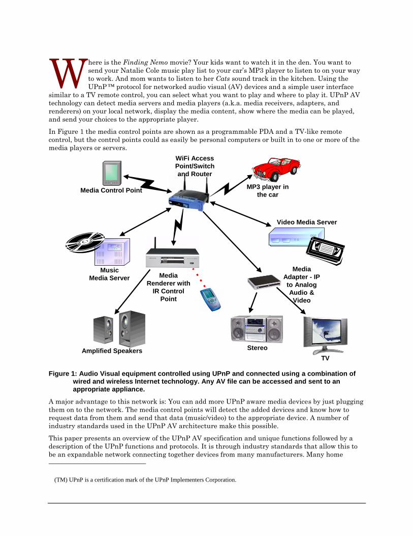
In Figure 1 the media control points are shown as a programmable PDA and a TV-like remote
control, but the control points could as easily be personal computers or built in to one or more of the
media players or servers.
Media Control Point
Music
Media Server
Amplified Speakers
Media
Renderer with
IR Control
Point
Stereo
TV
Video Media Server
Media
Adapter - IP
to Analog
Audio &
Video
WiFi Access
Point/Switch
and Router
MP3 player in
the car
Figure 1: Audio Visual equipment controlled using UPnP and connected using a combination of wired and wireless Internet technology. Any AV file can be accessed and sent to an appropriate appliance.
A major advantage to this network is: You can add more UPnP aware media devices by just plugging
them on to the network. The media control points will detect the added devices and know how to
request data from them and send that data (music/video) to the appropriate device. A number of
industry standards used in the UPnP AV architecture make this possible.
This paper presents an overview of the UPnP AV specification and unique functions followed by a
description of the UPnP functions and protocols. It is through industry standards that allow this to
be an expandable network connecting together devices from many manufacturers. Many home
(TM) UPnP is a certification mark of the UPnP Implementers Corporation.
W
- 2 -
equipment manufacturers may find the standards used in the UPnP AV specification a little
mystifying. However, as with many other components used in AV equipment, these software
components can be purchased from companies such as Allegro Software Development Corporation1
or free versions from Intel’s Web site2. The free versions are usually not sized for the lower cost home
equipment and may not support a variety of embedded operating systems.
There is a fine tutorial on all aspects of developing UPnP enabled devices at another of the Intel
Web3 sites, see the Resources section at the end of this paper.
UPnP AV Overview
The UPnP Audio Visual (AV) specifications4 define a set of UPnP device and service templates that
specifically target home environments with consumer electronic (CE) equipment such as TVs, VCRs,
DVD players, stereo systems, MP3 players, and PCs. CE device refers to any equipment that
interacts with entertainment content such as movies, audio, and still images.
In today’s home, CE devices interoperate with each other by using dedicated cables or by hand
carrying CDs and DVDs to devices. The UPnP AV specification enables CE devices to use a digital
network to interoperate with each other instead of dedicated analog cables. This network-wide
interoperability allows CE devices to distribute entertainment content throughout the home network
via CAT5 (Ethernet) cables or WiFi (wireless) connections.
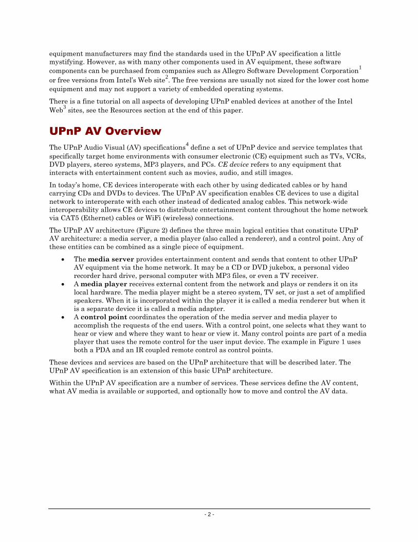
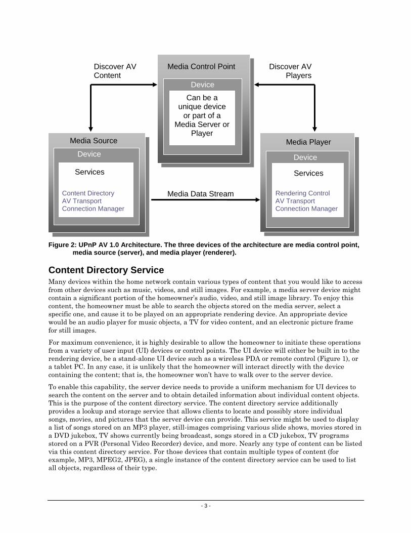
The UPnP AV architecture (Figure 2) defines the three main logical entities that constitute UPnP
AV architecture: a media server, a media player (also called a renderer), and a control point. Any of
these entities can be combined as a single piece of equipment.
The media server provides entertainment content and sends that content to other UPnP
AV equipment via the home network. It may be a CD or DVD jukebox, a personal video
recorder hard drive, personal computer with MP3 files, or even a TV receiver.
A media player receives external content from the network and plays or renders it on its
local hardware. The media player might be a stereo system, TV set, or just a set of amplified
speakers. When it is incorporated within the player it is called a media renderer but when it
is a separate device it is called a media adapter.
A control point coordinates the operation of the media server and media player to
accomplish the requests of the end users. With a control point, one selects what they want to
hear or view and where they want to hear or view it. Many control points are part of a media
player that uses the remote control for the user input device. The example in Figure 1 uses
both a PDA and an IR coupled remote control as control points.
These devices and services are based on the UPnP architecture that will be described later. The
UPnP AV specification is an extension of this basic UPnP architecture.
Within the UPnP AV specification are a number of services. These services define the AV content,
what AV media is available or supported, and optionally how to move and control the AV data.
- 3 -
Device
Media Control Point
Device
Services
Media Source
Content Directory AV Transport Connection Manager
Device
Services
Media Player
Rendering Control AV Transport Connection Manager
Media Data Stream
Discover AV Content
Discover AV Players
Can be a unique device
or part of a Media Server or
Player
Figure 2: UPnP AV 1.0 Architecture. The three devices of the architecture are media control point, media source (server), and media player (renderer).
Content Directory Service Many devices within the home network contain various types of content that you would like to access
from other devices such as music, videos, and still images. For example, a media server device might
contain a significant portion of the homeowner’s audio, video, and still image library. To enjoy this
content, the homeowner must be able to search the objects stored on the media server, select a
specific one, and cause it to be played on an appropriate rendering device. An appropriate device
would be an audio player for music objects, a TV for video content, and an electronic picture frame
for still images.
For maximum convenience, it is highly desirable to allow the homeowner to initiate these operations
from a variety of user input (UI) devices or control points. The UI device will either be built in to the
rendering device, be a stand-alone UI device such as a wireless PDA or remote control (Figure 1), or
a tablet PC. In any case, it is unlikely that the homeowner will interact directly with the device
containing the content; that is, the homeowner won’t have to walk over to the server device.
To enable this capability, the server device needs to provide a uniform mechanism for UI devices to
search the content on the server and to obtain detailed information about individual content objects.
This is the purpose of the content directory service. The content directory service additionally
provides a lookup and storage service that allows clients to locate and possibly store individual
songs, movies, and pictures that the server device can provide. This service might be used to display
a list of songs stored on an MP3 player, still-images comprising various slide shows, movies stored in
a DVD jukebox, TV shows currently being broadcast, songs stored in a CD jukebox, TV programs
stored on a PVR (Personal Video Recorder) device, and more. Nearly any type of content can be listed
via this content directory service. For those devices that contain multiple types of content (for
example, MP3, MPEG2, JPEG), a single instance of the content directory service can be used to list
all objects, regardless of their type.
- 4 -
Connection Manager Service The connection manager service enables modeling of streaming capabilities of AV devices and the
binding of those capabilities between devices. Each device that sends or receives a stream according
to the UPnP AV device model will have one instance of the connection manager service. This service
provides a mechanism for control points to:
1. Perform capability matching between server devices and renderer devices.
2. Find information about current transfers in the network.
3. Set up and tear down connections between devices.
When making connections, the connection manager is the interface between the control points and
the TCP/IP stack.
AV Transport Service The AV transport service enables control over the transport of audio and video streams. This service
type defines a common model for AV transport control suitable for a generic user interface. It can be
used to control a wide variety of disc, tape, and solid-state media devices such as CD players, VCRs,
and MP3 players. A minimal implementation of this service can be used to control tuners.
This service type is related to the connection manager service type, which describes AV connection
setup procedures, and the content directory service, which offers information about the resource
stored on the media. AV transport can also retrieve any metadata embedded in the resource itself.
The AV transport service does not schedule recording.
Although most media will be sent across the network as data it may be more efficient to transfer the
media data stream using other means. An example is when a personal video recorder is the media
source and a TV set is the medial player. A TCP/IP connection would not be as efficient as an s-video
connection. Using a transfer medium that is not part of the TCP/IP network is called an out of band
transfer. These transfers are not defined by the UPnP AV specification but are recommended and
supported by the manufacturer of the media equipment.
Rendering Control Most rendering devices contain a number of dynamically configurable attributes that affect how the
current content is rendered. For example, video devices, such as TVs, allow user control of display
characteristics such as brightness and contrast, where audio devices allow control of audio
characteristics such as volume, balance, and equalizer settings. The rendering control service is
intended to provide control points with the ability to query and/or adjust any rendering attribute
that the device supports.
The rendering control service enables a control point to:
Discover the attributes supported by the device.
Retrieve the current setting of any supported attribute.
Change the setting of any modifiable attribute.
Restore the settings defined by a named preset.
The rendering control service does not:
Control the flow of the associated content (for example, Play, Stop, Pause, Seek).
Provide a mechanism to list locally stored content.
Provide a mechanism to select the content that is to be rendered.
Provide a mechanism to send content to another device.
Media Renderer
The media renderer is based on a special-purpose UPnP device template to be used to enable and
support any consumer electronic (CE) device capable of rendering or playing AV content received

- 5 -
from the home network. It provides a set of rendering controls that allow a control point to control
how the specified AV content is played. This includes controlling various features such as brightness,
contrast, and volume.
A media renderer may come in different forms. Today the most common is the media adapter. It
converts digital IP data into analog audio or video signals. Many companies offer these and most are
called media adapters or media receivers.
Examples of a media renderer include traditional devices such as TVs and stereo systems. Some
more current examples include digital devices such as MP3 players and electronic picture frames
(EPFs). Although most devices typically render a specific type of content, a media renderer can
support a number of different data formats and transfer protocols. For example, a sophisticated
implementation of a TV media renderer can also support MP3 data, so that the TV speakers can be
used to play MP3 audio content.
The media renderer device template is simple. It is easy to implement on low-resource devices such
as an MP3 player. However, it can also be used to provide the high-end capabilities of such devices
as a PC.
A full-featured media renderer device template provides the following capabilities:
Control various rendering characteristics.
Expose the supported transfer protocols and data formats.
Control the flow of the content (for example, Fast Forward, and Rewind).
The media renderer device template does not enable control points to:
Send AV content to another device.
Retrieve any type of information associated with the content.
Media Server
The media server device is based on a special-purpose UPnP device template that is used to enable
and support services for any consumer electronic device that provides AV content (media) to other
UPnP devices on the home network. It provides its content via the content directory service
(CDS). A media server can handle any specific type of media, data format, and transfer protocol. The
CDS can present media organized by artist, album, track, and multiple personalized playlists. When
using a Windows PC as the server the media server’s CDS may have the directories MyPictures and
MyMusic as the top-level entries. Under MyMusic would be subdirectories of albums and playlists.
All of this is accessible to the user via the control point.
Examples of a media server include traditional devices such as VCRs, CD players, DVD players,
audiotape players, still-image cameras, camcorders, radios, TV Tuners, and set-top boxes. Additional
examples of a media server include new digital devices such as MP3 servers, PVRs, and PC-based
home media servers. Although these devices contain diverse AV content in various forms, the media
server (via the content directory service) can provide this content to the home network in a uniform
and consistent manner. This ability allows the media server to support traditional single-function
devices as well as more recent multifunction devices such as VCR-DVD players and the general
purpose home media server, which contains a wide variety of content such as MPEG2 video, CD
audio, MP3 and/or WMA audio, and JPEG images.
The media server device template is simple. It is easy to implement on low-resource devices such as
still-image cameras or MP3 players that can expose their local content to the home network. The
media server device template can also be used for high-end home media servers that contain dozens
of Gigabytes of heterogeneous content.
A full-featured media server device template provides clients with the following capabilities:
Enumerate and query any content that the media server can provide to the home network.

- 6 -
Negotiate a common transfer protocol and data format between the media server and target
device.
Control the flow of the content (for example, FF and REW).
Move (import) content to the media server from another device.
Most media servers currently available are implemented on personal computers. There is no reason
they could not be integrated with TV tuners, DVD changers, or network attached storage (NAS)
devices dedicated to storing music.
Media Control Point
As described earlier, the UPnP AV architecture defines the external interfaces of the media server
and media renderer so that a control point can manage the distribution of content desired by the end
user. However, the AV architecture does not define any of the internal structures of the server,
renderer, or control point. This is left entirely to the implementer. Nevertheless, some general
implementation models are commonplace. Here are a few:
1. At some point after the control point initializes itself, it can display an initial user interface
so that the end user can interact with the control point. The contents and layout of the user
interface is vendor dependent.
2. When a control point joins the network, it locates all media servers and media renderers in
the network. It does this using Simple Search/Discovery Protocol (SSDP). To locate media
servers in the network, the control point issues an SSDP IP-multicast (broadcast) request
packet to locate any UPnP device that implements the UPnP AV media server device
template. All devices that implement the media server template will respond to the request
with the URL of their description document. Media renderers are located in a similar
manner by using the media renderer device template.
3. After the servers and renderers are located, the control point obtains and parses each
device’s XML description document to determine the device’s exact capabilities; that is, its
UPnP services, actions, and state variables. If the device implements the desired capabilities,
the control point continues to interact with it.
4. For each media server found, the control point uses the server’s content directory service
(CDS) to list the content available from that server. Control points can collect CDS
information from multiple servers and aggregate it into a single view of the content that is
available from within the home, regardless of which media server provided it.
5. After the user selects the desired content, the control point determines the transfer protocols
and data formats supported for that particular content. This is done by examining the CDS
metadata for the selected object. Using the connection manager service on each renderer, the
control point can obtain the set of protocols and formats supported by each device.
6. The control point then compares the protocol or format information from the server’s CDS
and the renderer’s connection manager service to determine which renderer(s) can play the
desired content.
If a common protocol or format is identified, the control point invokes the connection manager
services on both the server and renderer to notify each device of the target protocol or format. In
response, the connection manager sets up and configures its internal network and media streaming
subsystems based on the identified common protocol or format.
7. After the connection manager configures each device, either the server or renderer returns a
notice of the AV transport service associated with the data path just set up. The control point
uses the returned AV transport notice to specify the content item to be transferred from the
server to the renderer.

- 7 -
8. When the user indicates the desired operation to be performed on the content (for example,
play) the appropriate actions on the AV transport service are invoked. After the content
begins to play, the user can select other operations, such as stop or pause.
9. As the content is being performed, the control point can provide a set of UI components that
allow the user to control how the content is performed. This includes various performance
characteristics such as volume and brightness. As the user adjusts various performance
characteristics, the control point invokes the appropriate action on the rendering control
service (RCS).
Today most control points are dedicated to a single media adapter/renderer. That control point will
search the local network for all UPnP enabled media servers and it will them make up a list of
available and compatible AV files. In Figure 1 there is a PDA used as a control point. This should be
an easy implementation but so far no one seems to have commercialized such software.
UPnP Overview
UPnP is the architecture for peer-to-peer networking of intelligent appliances, wireless devices,
home entertainment equipment, and computers of varying form factors. UPnP defines a set of
common services (protocols) that devices can use to join a network, describe themselves and their
capabilities, and enable other devices and people to use them without complicated set up or
configuration.
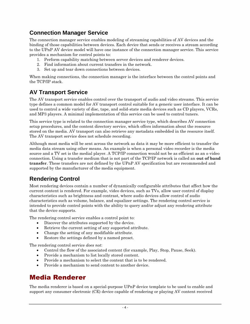
The equipment that supports UPnP are either devices or control points. Devices perform functions
(services) such as a media server or media player. Control points are used to detect and manage
devices. Often a control point is part of a device (see Figure 3).
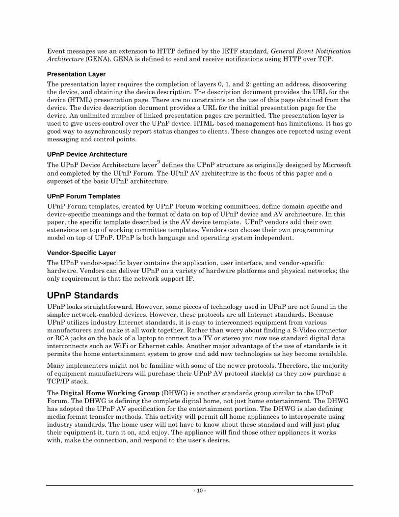
UPnP has six basic layers (see Figure 4): (0) IP addressing, (1) device discovery, (2) device
description, (3) action invocation or control, (4) event messaging, and (5) presentation or user
interface.
UPnP is a protocol for data transmission; it does not move byte codes or use ActiveX controls. It is
operating system independent but is built on various existing network standards. UPnP works in a
peer-to-peer or ad hoc network. Device IP addresses can be hard wired, use a DHCP server, or use
Auto IP to automatically choose from a range of addresses.
A control point, when added, can search the network for devices. When a device is added to a
network, it will advertise itself to let all control points know the device is on line. Once a device is
discovered, a description of the device and the services it provides is presented in an XML document.
Each device can have a unique presentation or Web home page. Its URL is sent to control points as
part of the description.
Control points can initiate a device action by sending a message to the device. The message is sent to
the URL obtained from the description presented by the device. The device notifies the control point
when the action is completed.
Often devices do not need to be told to perform their function, but they must report their status to
one or more control points. In UPnP, this status reporting is called event messaging – a simple push
model. Events are sent only to control points that have subscribed to a device’s event status
reporting.

- 8 -
Device
Service
Control Point
Device
Control Point
Service
Devices with services are
controlled; Web server
disseminates data.
Control points are
controllers. They are
usually Web clients.
Equipment can contain both
services and control points.
Figure 3: UPnP devices can be devices, control points, or both. Devices have services that can be monitored or controlled by a control point.
UPnP Function Layers UPnP devices represent embedded functionality through services. These services could include
turning off the device, scanning inputs for data, or similar functions. These services can be initiated
either by the device itself or by a control point. Some objects on the network can be both a control
point and a device. This is especially true for home AV devices.
There are six layers of functions of an UPnP enabled device or control point (Figure 4). Layers 0, 1,
and 2 exist in all devices and control points. Layers 3, 4, and 5 are optional. Control points (layer 3)
can initiate an action on a device. Many devices will have event messaging (layer 4) but not control
or presentation; they will create an event message and a control point listens for these event
messages. Devices can send data (the results of an action they have taken) without the initiation of a
control point. Some devices might just provide a user interface to the control point (layer 5). The
3 Control
0 Addressing
1 Discovery
2 Description
4 Eventing 5 Presentation
Figure 4: UPnP’s six layers of device functions: IP addressing, discovery, description of URLs and services, and optional control of other UPnP devices, event messaging, and presentation or the Web page for the device. Layers 0 through 2 exist in all UPnP-enabled devices.

- 9 -
control point will display the user interface of the device. This user interface can display events,
display status, or control the device.
The presentation layer appears to be required because a pointer to the presentation URL is part of
the device description. The presentation layer in the device is not required if the control point is
handling the device programmatically and not through a Web browser. Because every UPnP device
has a Web server, it is simple to use the browser in a control point as the front panel5 of the device.
Device Addressing Layer
The addressing layer is where control points and devices get their IP addresses. The IP addresses
can be hard wired, can come from a DHCP server, or can use Auto IP to assign an IP address. The
UPnP device first checks for the presence of a DHCP server and if none is present the device then
uses the Auto IP function.
A DHCP server is part of a network router that assigns IP addresses to equipment as they connect to
the local network. These addresses are from a range of addresses assigned by the user.
Auto IP is a draft Internet Engineering Task Force6 (IETF) standard, Dynamic Configuration of IPv4
Link-Local Addresses. Auto IP assigns an IP address to the device from a range of nonroutable
addresses. Once assigned, the device tests the address to determine whether it is in use by another
device.
Device Discovery Layer
The discovery layer is where control points searches for UPnP devices on the network or UPnP
devices advertising their presence. When a device is added to a network, it advertises its presence by
sending a message via a multicast variant of HTTP over UDC. A control point will answer with a
message using unicast UDP.
Device Description Layer
Once a control point discovers a device, it obtains a description from the device. The information sent
by the device is expressed in an Extensible Markup Language (XML) document. XML is used
throughout the UPnP implementation.
A description includes a device type, URLs for control and eventing, icons, and a URL for
presentation, as well as the manufacturer’s name, serial number, product code, and other similar
information. Device types are defined by the UPnP Forum7. Each device type can have one or more
UPnP templates to define the content and presentation of data.
Control Layer
To initiate device action, a control point sends a control message using the definitions from the
device description document. The device completes the action and responds using SOAP.
To exchange information, the control layer uses a World Wide Web Consortium8 (W3C) standard,
Simple Object Access Protocol (SOAP). SOAP is defined as a “lightweight, XML-based protocol for
exchange of information in a decentralized, distributed environment.”
Event Messaging Layer
The event messaging layer is a simple push model; control points listen for notifications of UPnP
device state changes. Actually, it is a little more complex. To get event messages, control points
subscribe to event messages for a specific service within a device. On a network, there can be
multiple control points and multiple UPnP enabled devices. A control point might listen to multiple
services, but not all. The subscription and unsubscription of events allow control points to be
selective. When a service within a device has an event, it sends an event message to all current
subscribers to that event. This way all subscribers have current knowledge of the device state.
- 10 -
Event messages use an extension to HTTP defined by the IETF standard, General Event Notification
Architecture (GENA). GENA is defined to send and receive notifications using HTTP over TCP.
Presentation Layer
The presentation layer requires the completion of layers 0, 1, and 2: getting an address, discovering
the device, and obtaining the device description. The description document provides the URL for the
device (HTML) presentation page. There are no constraints on the use of this page obtained from the
device. The device description document provides a URL for the initial presentation page for the
device. An unlimited number of linked presentation pages are permitted. The presentation layer is
used to give users control over the UPnP device. HTML-based management has limitations. It has go
good way to asynchronously report status changes to clients. These changes are reported using event
messaging and control points.
UPnP Device Architecture
The UPnP Device Architecture layer9 defines the UPnP structure as originally designed by Microsoft
and completed by the UPnP Forum. The UPnP AV architecture is the focus of this paper and a
superset of the basic UPnP architecture.
UPnP Forum Templates
UPnP Forum templates, created by UPnP Forum working committees, define domain-specific and
device-specific meanings and the format of data on top of UPnP device and AV architecture. In this
paper, the specific template described is the AV device template. UPnP vendors add their own
extensions on top of working committee templates. Vendors can choose their own programming
model on top of UPnP. UPnP is both language and operating system independent.
Vendor-Specific Layer
The UPnP vendor-specific layer contains the application, user interface, and vendor-specific
hardware. Vendors can deliver UPnP on a variety of hardware platforms and physical networks; the
only requirement is that the network support IP.
UPnP Standards UPnP looks straightforward. However, some pieces of technology used in UPnP are not found in the
simpler network-enabled devices. However, these protocols are all Internet standards. Because
UPnP utilizes industry Internet standards, it is easy to interconnect equipment from various
manufacturers and make it all work together. Rather than worry about finding a S-Video connector
or RCA jacks on the back of a laptop to connect to a TV or stereo you now use standard digital data
interconnects such as WiFi or Ethernet cable. Another major advantage of the use of standards is it
permits the home entertainment system to grow and add new technologies as hey become available.
Many implementers might not be familiar with some of the newer protocols. Therefore, the majority
of equipment manufacturers will purchase their UPnP AV protocol stack(s) as they now purchase a
TCP/IP stack.
The Digital Home Working Group (DHWG) is another standards group similar to the UPnP
Forum. The DHWG is defining the complete digital home, not just home entertainment. The DHWG
has adopted the UPnP AV specification for the entertainment portion. The DHWG is also defining
media format transfer methods. This activity will permit all home appliances to interoperate using
industry standards. The home user will not have to know about these standard and will just plug
their equipment it, turn it on, and enjoy. The appliance will find those other appliances it works
with, make the connection, and respond to the user’s desires.

- 11 -
Some protocols used to make up UPnP were mentioned in the description of the UPnP functions
earlier in this paper. Complete information can be found at the UPnP Forum, W3C, and IETF Web
sites.
The UPnP protocols (Figure 5) are:
UPnP starts with IP (Internet Protocol).
UDP is used for discovery because it is multicast.
TCP is used for description, control, and presentation.
HTTP Multicast over UDP is used to send a broadcast message to the network to advertise
the presence of a UPnP device and a control point uses HTTP Multicast over UDP to send a
query to find out what UPnP devices are there. Both use extensions to HTTP; GENA
(General Event Notification Architecture) and SSDP (Simple Search/Discovery Protocol).
SOAP (Simple Object Access Protocol) is used in the control function.
HTML is the basis of a user interface.
Auto IP is a method of assigning IP address when there is no DHCP server or the device has
no hardwired IP address.
All UPnP messages are framed using XML, the standard data format protocol.
GENA, SSDP, and Auto IP standards are defined by the IETF. SOAP is defined by the W3C. HTTP
Multicast over UDP is not part of the HTTP standard; it was created for use in UPnP.
Figure 5: UPnP protocol layers; some may be unfamiliar to network device implementers. Automatic discovery and description require new protocols such as GENA, SSDP, and SOAP.

- 12 -
Conclusion
The UPnP AV architecture defines the basic interfaces that enable device manufacturers to develop
and deploy multimedia products that interoperate with devices from other manufacturers. Many
media manufacturers will find the development of the basic UPnP stack and the UPnP AV
specification exceeds their available expertise or time to implement. Most manufacturers will
purchase these software stacks from tools vendors, such as Allegro Software Development1, to save
themselves months of development time.
Because the AV architecture uses industry standards and defines the basic interoperability
mechanisms, manufacturers are free to add innovative capabilities to their products. This simplifies
the development process and allows vendors to provide self-configuring, interoperable products to
the marketplace with lower development costs. The combination of lower development and
installation costs allows products to be brought to the marketplace at price points and convenience
levels for mass-market adoption. Consequently, the UPnP AV architecture makes it possible for
mass-market consumers to finally realize the compelling benefits of access to rich multimedia
content “anytime, anywhere.”
Today, the biggest hole in the implementation of this technology is how to circumvent the copyright
restrictions of transmitting DVD content across a digital network so it may be stored and played on a
variety of devices. CD content copying for personal use is permitted via a grandfather clause but not
so with DVD content.
Note: Some text for this paper was extracted from the UPnP Forum Web site7, Microsoft UPnP
Device Architecture Web site9, Intel Developer’s Web site10, and articles written by Edward
Steinfeld11.
Author
Edward F. Steinfeld
Embedded-Computing Market Consultant
Automata International Marketing
25 Arbor Glen Drive
Stow, MA 01775-1258 USA
Telephone: +1 978.8978-3127
E-mail: [email protected]
URL: www.go-embedded.com
Ed has more than 25 years experience in realtime and embedded computing. He began as a
programmer writing code and designing hardware to test hybrid circuit boards for Picker X-ray. He
has marketed embedded and realtime products to OEMs and resellers for Digital Equipment
Corporation, VenturCom, Inc., and Phar Lap Software. His international experience includes a stint
in Hong Kong as a Far East Channels Manager and responsibility for international OEM marketing
and sales in Europe and the Pacific Rim.
Ed, as Automata International Marketing, is providing market research, planning, and services to
the embedded computing industry. Ed has been an evangelist for embedded Web products since 1995
when he announced the first “World’s Smallest Web Server” for Phar Lap Software. At the time, it
may have been the first commercial diskless Web server.
- 13 -
Resources
1 UPnP development tools for home equipment, Allegro Software Development Corporation,
http://www.allegrosoft.com
2 Intel UPnP development tools, http://www.intel.com/technology/UPnP/download.htm
3 UPnP tutorial http://www.intel.com/technology/UPnP/tutorial.htm
4 UPnP AV 1.0 Specifications, UPnP Forum
http://www.upnp.org/standardizeddcps/mediaserver.asp
5 Internet-appliance technology automates test equipment by Edward Steinfeld
http://www.go-embedded.com/EDN%20Article.pdf
6 Internet Engineering Task Force (IETF) http://www.ietf.org/internet-drafts/
7 UPnP Forum http://www.upnp.org
8 World Wide Web Consortium (W3C) http://www.w3.org
9 UPnP Device Architecture, Microsoft Corporation
http://www.upnp.org/download/UPnPDA10_20000613.htm
10 Intel Research and Development, http://www.intel.com/labs/connectivity/upnp/ or
http://www.intel.com/technology/UPnP/download/UPnP_AV_Arch.pdf
11 Devices That Play Together, Work Together by Edward Steinfeld
http://www.go-embedded.com/EDN%20UPnP.pdf