home-world.chhome-world.ch/media/productfile/f/e/feria_patiocover_3x54.pdfPDF filehome-world.ch
HOME AUTOMATION
INDEX
INTRODUCTION
SINGLE PHASE POWER UNIT DL 2101T70 POWER SUPPLY DL 2101T71 PUSH‐BUTTON INTERFACE DL 2101T72 DOUBLE PUSH‐BUTTON DL 2101T74 SMOKE DETECTOR DL 2101T75 TEMPERATURE CONTROLLER DL 2101T76 PRESENCE DETECTOR AND BRIGHTNESS SENSOR DL 2101T79 BINARY OUTPUT DL 2101T80 UNIVERSAL DIMMER DL 2101T81 SHUTTER ACTUATOR DL 2101T82 VALVE ACTUATOR DL 2101T83 INFRARED TRANSMITTER/RECEIVER & DECODER DL 2101T84 SCENE/EVENT CONTROLLER DL 2101T85 TEXT DISPLAY/CLOCK SWITCH DL 2101T89 USB INTERFACE DL 2101T90 SOCKETS WITH LAMPS DL 2101T91 VENETIAN DRIVE DL 2101T92 COLOUR TOUCH PANEL DL 2101T95 PLC LOGO! and COMMUNICATION MODULE DL 6BK1 VOLTAGE ADAPTATION MODULE DL 2101T70VT PROGRAMMING SOFTWARE DL SW‐ETS THREE‐LEVEL FRAME DL 2100‐3M CONNECTING LEADS DL 1155EIB
CONFIGURATIONS

HOME AUTOMATION
INTRODUCTION
The houses and all the other buildings that the man has erected for his own activities (offices, schools, shops, factories, etc.) have been and still are in continuous progress. In fact, so many improvements have been added during the years to reach, in particular, the following objectives: higher safety, possibility to live more comfortably, possibility to better perform your job and your activities.
The traditional installation system for buildings has been for years mainly concentrated on the distribution and control of the electrical energy, but today this is not sufficient any more. In modern systems the requirements have changed and have multiplied, mainly for what concerns advantage, flexibility, centralized and decentralized controls, intelligent connections of different operating sections and systems, communication easiness, environmental compatibility and minimization of the use of energy and of the operating costs.
A traditional electrical plant with such characteristics is more complex and involves a higher number of components with the relevant consequences: a tangle of cables, a wide range of non compatible equipment and components, a demanding design work and, most of all, an expensive system.
Therefore, a traditional plant is practically inadequate to fully satisfy such requirements, at minimum design and operating costs.
The home automation system offers the right solution.
This type of system, custom tailored to respond to the most current requirements relevant to the electrical plant, needs just a single bipolar conductor through which all the end users connected to the bus communicate among them.
The products are compatible and interoperating among them and, therefore, can live together in the system even if they come from different manufacturers.
The controls, the signals, the necessary data for the supervision and all the parameters of the plant have as a single transmission media a “single bipolar cable”, the bus cable.
Such circumstance implies a drastic reduction of the times for laying the conductors and all that is needed for their installation.
The functionality of the plant is then determined by means of a software package, through which the single components all connected in parallel to the single necessary bipolar line gain their “individuality”, that is can be identified one by one, through an address, that is the identification number of the device, and a “conscience” of their tasks, that is the personalized operating program for the type of plant where they are installed.
The consequences of what has been done are immediate:
* the components are of general use and are personalized through a suitable software
* the tuning of the functions according to the needs of the user can be performed at the end of the installation
* modifications subsequent to the installation can be performed from any point of the plant and at any time without interrupting its functionality
Another advantage that is not immediately evident, but that must be considered in the right perspective is the possibility of realizing a remarkable energy saving by distributing the energy where and when it is needed, by interrupting it at the and by supplying it according to a suitable time program.
The devices used in the system must be able to perform the same functions for the automatic management of the buildings, both commercial and residential.
The performed functions are the following:
control of the light control of the shutters control of the heating management of the loads display, information, operator control, monitoring and detection
interfaces and other systems
HOME AUTOMATION
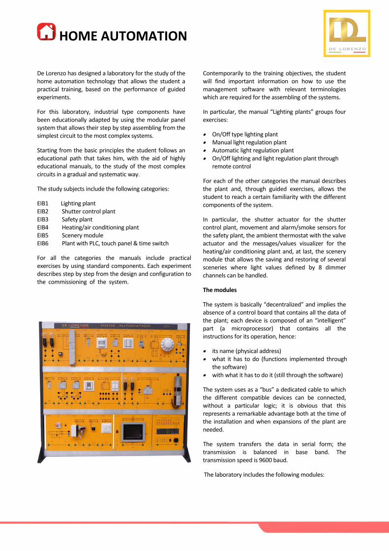
De Lorenzo has designed a laboratory for the study of the home automation technology that allows the student a practical training, based on the performance of guided experiments.
For this laboratory, industrial type components have been educationally adapted by using the modular panel system that allows their step by step assembling from the simplest circuit to the most complex systems.
Starting from the basic principles the student follows an educational path that takes him, with the aid of highly educational manuals, to the study of the most complex circuits in a gradual and systematic way.
The study subjects include the following categories:
EIB1 Lighting plant EIB2 Shutter control plant EIB3 Safety plant EIB4 Heating/air conditioning plant EIB5 Scenery module EIB6 Plant with PLC, touch panel & time switch
For all the categories the manuals include practical exercises by using standard components. Each experiment describes step by step from the design and configuration to the commissioning of the system.
Contemporarily to the training objectives, the student will find important information on how to use the management software with relevant terminologies which are required for the assembling of the systems.
In particular, the manual “Lighting plants” groups four exercises:
On/Off type lighting plant Manual light regulation plant Automatic light regulation plant On/Off lighting and light regulation plant through
remote control
For each of the other categories the manual describes the plant and, through guided exercises, allows the student to reach a certain familiarity with the different components of the system.
In particular, the shutter actuator for the shutter control plant, movement and alarm/smoke sensors for the safety plant, the ambient thermostat with the valve actuator and the messages/values visualizer for the heating/air conditioning plant and, at last, the scenery module that allows the saving and restoring of several sceneries where light values defined by 8 dimmer channels can be handled.
The modules
The system is basically “decentralized” and implies the absence of a control board that contains all the data of the plant; each device is composed of an “intelligent” part (a microprocessor) that contains all the instructions for its operation, hence:
its name (physical address) what it has to do (functions implemented through
the software) with what it has to do it (still through the software)
The system uses as a “bus” a dedicated cable to which the different compatible devices can be connected, without a particular logic; it is obvious that this represents a remarkable advantage both at the time of the installation and when expansions of the plant are needed.
The system transfers the data in serial form; the transmission is balanced in base band. The transmission speed is 9600 baud.
The laboratory includes the following modules:
HOME AUTOMATION
The Modules
SINGLE PHASE POWER UNIT
DL 2101T70
Residual current circuit breaker with overload protection for connection to the single‐phase mains. Technical specifications Rated current In = 16 A Rated voltage Un = 230 Vac Minimum operating voltage Umin = 100 V Sensitivity Id = 30 mA Output terminals L and N, with pilot lamp.
POWER SUPPLY
DL 2101T71
The power supply unit provides and monitors the power necessary for the system operation with safety extra low voltage: the integrated choke prevents the data telegrams from short‐circuiting on the bus line. It has a voltage and current regulation and is therefore short‐circuit proof; it can supply DC 24V power from an additional pair of terminals. Technical specifications Power supply: 120÷230 Vac, 50‐60 Hz Output voltage (Bus): 29 Vdc Short‐circuit current: limited to 1.5 A Output voltage (SELV): 29 Vdc (no choke)
PUSH‐BUTTON INTERFACE
DL 2101T72
The push‐button interface is a binary input and output device with four channels; each of them may be used either as an input for potential‐free switch/push button contacts or as an output for control of a light emitting diode (LED). The module is complete with two single‐pole switches to operate very easily on it showing the interfacing possibilities with a traditional domestic plant. Technical specifications Power supply: Bus line Inputs: 4 binary channels
HOME AUTOMATION
DOUBLE PUSH‐BUTTON
DL 2101T74
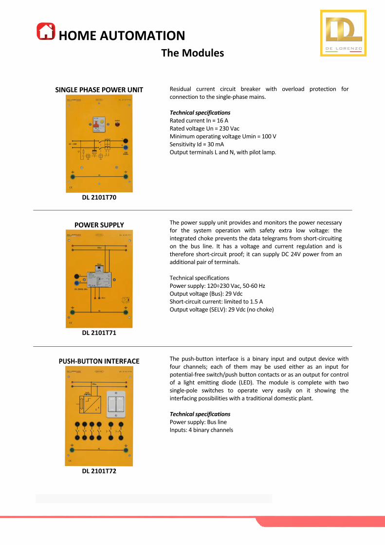
This module has four switch buttons that, horizontally aligned, may be used as a pair of buttons (e.g. for defined switching/dimming, or control of shutters and blinds), or as single buttons for sending values, single‐button switching/dimming or single button control of blinds. Technical specifications Power supply: Bus line via bus coupling unit.
SMOKE DETECTOR
DL 2101T75
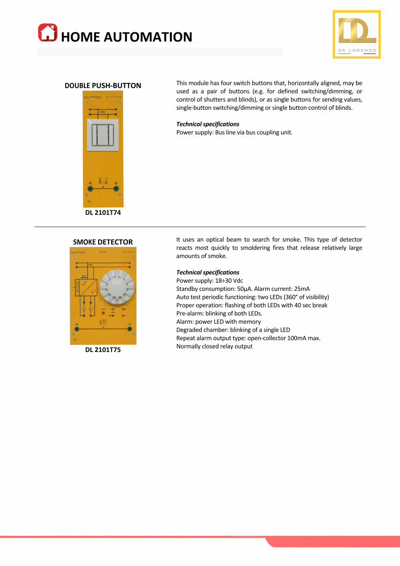
It uses an optical beam to search for smoke. This type of detector reacts most quickly to smoldering fires that release relatively large amounts of smoke. Technical specifications Power supply: 18÷30 Vdc Standby consumption: 50μA. Alarm current: 25mA Auto test periodic functioning: two LEDs (360° of visibility) Proper operation: flashing of both LEDs with 40 sec break Pre‐alarm: blinking of both LEDs. Alarm: power LED with memory Degraded chamber: blinking of a single LED Repeat alarm output type: open‐collector 100mA max. Normally closed relay output

HOME AUTOMATION
TEMPERATURE CONTROLLER
DL 2101T76
The room temperature controller is especially designed for usage in rooms which are heated and/or cooled and whose temperatures are controlled depending on up to four room operating modes (comfort mode, pre‐comfort mode, energy‐savings mode and protection mode). It can be used as a two point control (thermostat) or as a continuous controller (P or PI controller). Technical specifications Power supply: Via the bus transceiver module Measuring range: 0 ÷ + 40°C
PRESENCE DETECTOR AND
BRIGHTNESS SENSOR
DL 2101T79
This device is a presence/motion detector with integrated constant light level control. It communicates via KNX with actuators or other KNX devices. The detector signal can be analyzed via two separate communication channels, termed motion detector and presence detector. Another main application is the automatic control of the lighting on an office workplace. It contains an independent light sensor with integrated 2‐level light control (switching) and constant light level control (dimming). Technical specifications Power supply via bus line KNX Current drain: approx. 10 mA Presence detection type: passive infrared (PIR) Range: horizontal 360°, vertical approx. 105°, 288 sectors Brightness measurement type: contrast Range: 20…1000 Lux Different installation heights (from 2.5m to 5.0m)
BINARY OUTPUT
DL 2101T80
The binary output is a device that can switch two separate groups of electric devices via its two outputs. Each of the outputs can be assigned various tasks depending on the application program used: i.e. the binary output consists of the device (HW) and its application program (SW). Technical specifications Power supply: Bus line Outputs: 2 volt‐free contacts Rated voltage: 230 Vac, 47÷63 Hz Switching current at 24 Vdc: 10 A (resistive load), 4 A (inductive load) Switching power: 1 kW (incandescent lamp) or 500 W (fluorescent lamp)
HOME AUTOMATION
UNIVERSAL DIMMER
DL 2101T81
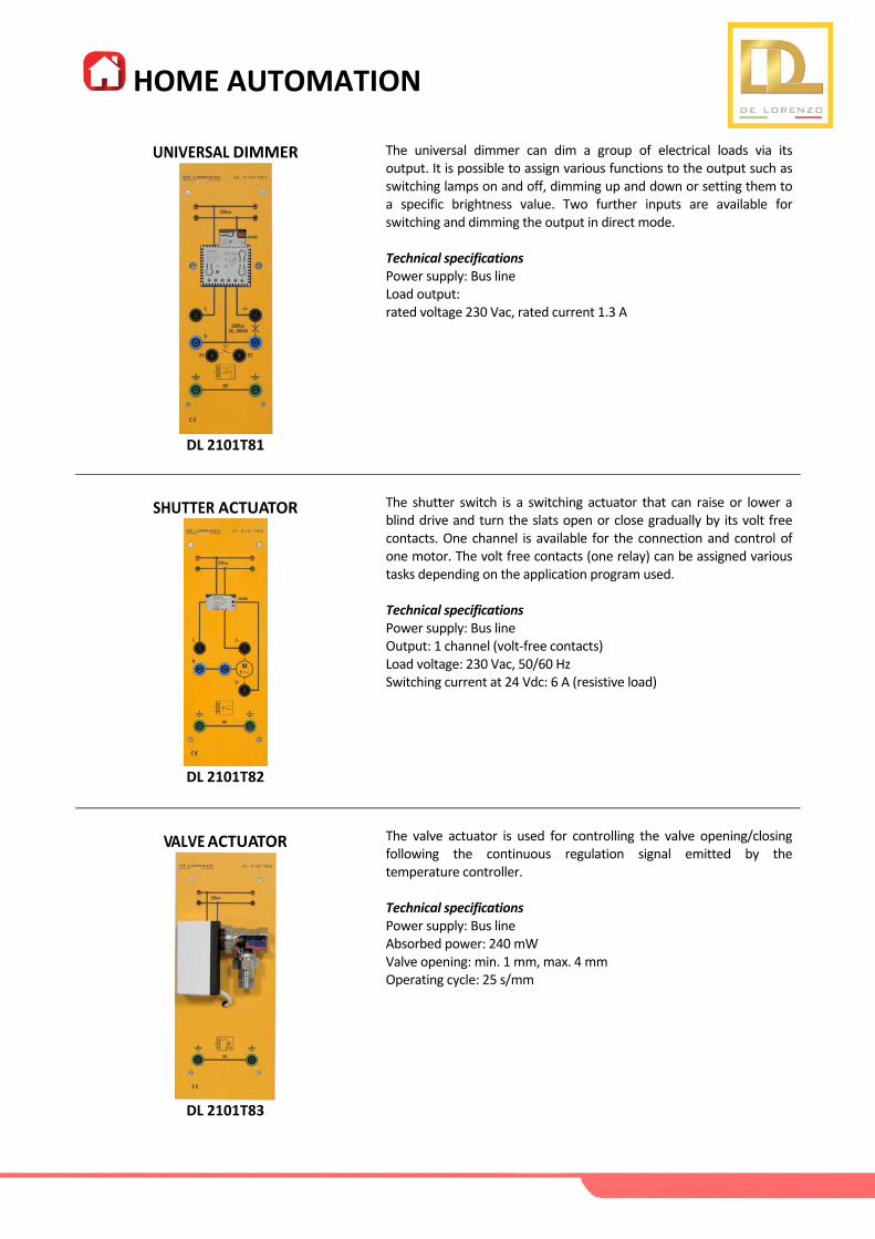
The universal dimmer can dim a group of electrical loads via its output. It is possible to assign various functions to the output such as switching lamps on and off, dimming up and down or setting them to a specific brightness value. Two further inputs are available for switching and dimming the output in direct mode. Technical specifications Power supply: Bus line Load output: rated voltage 230 Vac, rated current 1.3 A
SHUTTER ACTUATOR
DL 2101T82
The shutter switch is a switching actuator that can raise or lower a blind drive and turn the slats open or close gradually by its volt free contacts. One channel is available for the connection and control of one motor. The volt free contacts (one relay) can be assigned various tasks depending on the application program used. Technical specifications Power supply: Bus line Output: 1 channel (volt‐free contacts) Load voltage: 230 Vac, 50/60 Hz Switching current at 24 Vdc: 6 A (resistive load)
VALVE ACTUATOR
DL 2101T83
The valve actuator is used for controlling the valve opening/closing following the continuous regulation signal emitted by the temperature controller. Technical specifications Power supply: Bus line Absorbed power: 240 mW Valve opening: min. 1 mm, max. 4 mm Operating cycle: 25 s/mm

HOME AUTOMATION
INFRARED TRANSMITTER/RECEIVER & DECODER
DL 2101T84
For wireless control of actuators. The IR remote control transmits infrared signals received by the IR‐receiver and downloaded to the IR‐decoder, which transforms these signals into appropriate bus telegrams. Technical specifications of transmitter Power supply: 2 alkaline batteries LR03/AAA, 1.5 V Wavelength 890 nm. Range: approx. 20 m Transmission frequency: 455 kHz Adjustable channels: 16 of 64. Technical specifications of receiver/decoder Power supply: Bus line System reception field: 5 cm ÷ 8 m Remote control, focused beam: max. 20m
SCENE/EVENT CONTROLLER
DL 2101T85
The scene/event controller, with its application program, can define and process either scenes control and event programs; the user can program and recall up to eight scenes and can construct also up to eight event programs. Technical specifications Power supply: Bus line Sceneries: 1...4 (groups for each scenery 1...8) Stored values: 8 max. with 8 bits or 1 bit (max. 4 with 8 bits and max. 2 with 1 bit) Sceneries recall: 1...4 sceneries via push‐button or transmitter
TEXT DISPLAY/CLOCK SWITCH
DL 2101T89
The following display and operating functions can be configured: switching, switching with forced control, dimming, sun protection control, recall and save scenes, sending and displaying values, display of values and text/operating messages. Alarm messages are displayed on special alarm pages. It is additionally equipped with a weekday switching function for up to 40 timer tasks. These commands can be configured for each of the 8 configurable control functions. Technical specifications Power supply: via the KNX bus line Current consumption: 6,8/8,6 mA (without/with display background lighting) 8 capacitive touch buttons Dot‐matrix LCD for HMI
HOME AUTOMATION
USB INTERFACE
DL 2101T90
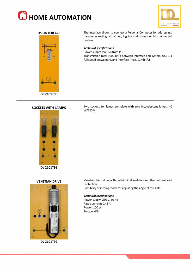
The interface allows to connect a Personal Computer for addressing, parameter setting, visualizing, logging and diagnosing bus connected devices. Technical specifications Power supply: via USB from PC. Transmission rate: 9600 bit/s between interface and system, USB 1.1 full speed between PC and Interface (max. 12Mbit/s).
SOCKETS WITH LAMPS
DL 2101T91
Two sockets for lamps complete with two incandescent lamps: 40 W/220 V.
VENETIAN DRIVE
DL 2101T92
Venetian blind drive with built‐in limit switches and thermal overload protection. Possibility of inching mode for adjusting the angle of the slats. Technical specifications Power supply: 230 V, 50 Hz Rated current: 0.45 A. Power: 100 W Torque: 4Nm
HOME AUTOMATION
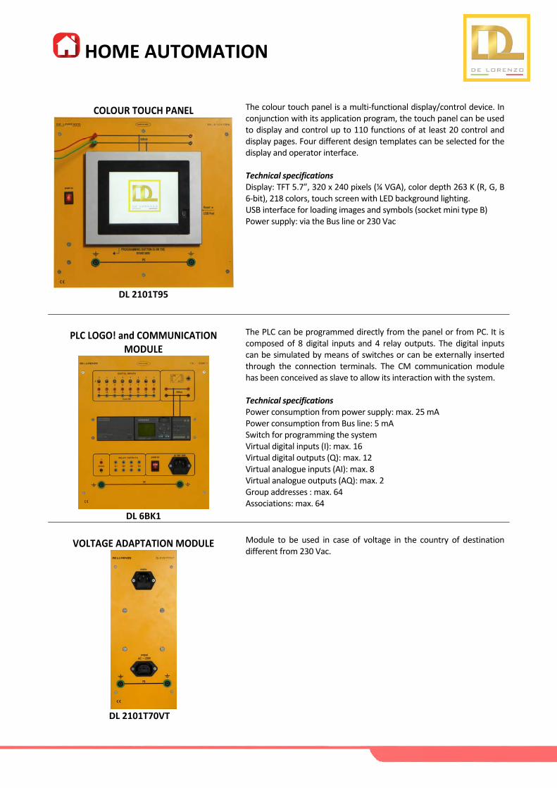
COLOUR TOUCH PANEL
DL 2101T95
The colour touch panel is a multi‐functional display/control device. In conjunction with its application program, the touch panel can be used to display and control up to 110 functions of at least 20 control and display pages. Four different design templates can be selected for the display and operator interface. Technical specifications Display: TFT 5.7”, 320 x 240 pixels (¼ VGA), color depth 263 K (R, G, B 6‐bit), 218 colors, touch screen with LED background lighting. USB interface for loading images and symbols (socket mini type B) Power supply: via the Bus line or 230 Vac
PLC LOGO! and COMMUNICATION
MODULE
DL 6BK1
The PLC can be programmed directly from the panel or from PC. It is composed of 8 digital inputs and 4 relay outputs. The digital inputs can be simulated by means of switches or can be externally inserted through the connection terminals. The CM communication module has been conceived as slave to allow its interaction with the system. Technical specifications Power consumption from power supply: max. 25 mA Power consumption from Bus line: 5 mA Switch for programming the system Virtual digital inputs (I): max. 16 Virtual digital outputs (Q): max. 12 Virtual analogue inputs (AI): max. 8 Virtual analogue outputs (AQ): max. 2 Group addresses : max. 64 Associations: max. 64
VOLTAGE ADAPTATION MODULE
Module to be used in case of voltage in the country of destination different from 230 Vac.
DL 2101T70VT

HOME AUTOMATION
PROGRAMMING SOFTWARE
DL SW‐ETS
Configuration tool software to design and configure intelligent home and building control installations. It focuses on all users of the system, from the beginner up to the skilled and experienced partner or installer. It supports you in the realization of home and building automation projects in various phases and tasks as project planning and design, commissioning, project‐documentation, diagnostics and troubleshooting.
THREE‐LEVEL FRAME
DL 2100‐3M
Metal frame for fitting the modules of the laboratory.
CONNECTING LEADS
DL 1155EIB
Set of connecting leads.

HOME AUTOMATION
CONFIGURATIONS
CODE DESCRIPTION 1 2 3 4 5 6 TOTAL
DL 2101T70
DL 2101T71
DL 2101T72
DL 2101T74
DL 2101T75
DL 2101T76
DL 2101T79
DL 2101T80
DL 2101T81
DL 2101T82
DL 2101T83
DL 2101T84
DL 2101T85
DL 2101T89
DL 2101T90
DL 2101T91
DL 2101T92
DL 2101T95
DL 6BK1
DL SW‐ETS
DL 2100‐3M
DL 1155EIB
SINGLE PHASE POWER UNIT
POWER SUPPLY
PUSH‐BUTTON INTERFACE
DOUBLE PUSH‐BUTTON
SMOKE DETECTOR
TEMPERATURE CONTROLLER
PRESENCE/BRIGHTNESS
BINARY OUTPUT
UNIVERSAL DIMMER
SHUTTER ACTUATOR
VALVE ACTUATOR
INFRARED T/R
SCENE/EVENT CONTROLLER
TEXT DISPLAY/CLOCK SWICTH
USB INTERFACE
SOCKETS WITH LAMPS
VENETIAN DRIVE
COLOUR TOUCH PANEL
PLC/COMM. MODULE
SOFTWARE ETS
PERSONAL COMPUTER
FRAME
CONNECTING LEADS
1
1
1
1
1
1
1
1
1
2
1
1
1
1
1
1
1
1
1
1
1
1
1
1
1
1
1
1
1
1
1
1
1
1
1
1
1
1
1
1
1
1
1
1
1
1
1
1
1
2
1
1
1
1
1
1
1
1
1
1
1
1
1
1
1
1
1
1
1
1
1
1
1
1
1
1
1
1
2
1
1
1
1
1
1
2
1
1
1
1
1
1
1
DL 2101T70VT ‐ VOLTAGE ADAPTATION MODULE ‐ in case of voltage different from 230 Vac
1 = LIGHTING PLANTS
2 = SHUTTER CONTROL PLANT
3 = SAFETY PLANT
4 = HEATING PLANT
5 = SCENERY MODULE
6= PLANT WITH PLC, TOUCH PANEL & TIME SWITCH


![Home [ ] · PDF fileHome Author: usuario Subject: Home Created Date: 12/17/2004 11:13:50 AM](https://static.fdocuments.us/doc/165x107/5a72e19f7f8b9aac538e08d1/home-a-home-author-usuario-subject-home-created-date-12172004-111350.jpg)