HOLLOW METAL HMMA 850 MANUAL STANDARD · fire-protection and smoke control rated hollow metal door...
64
FIRE-PROTECTION AND SMOKE CONTROL RATED HOLLOW METAL DOOR AND FRAME PRODUCTS FOURTH EDITION HOLLOW METAL MANUAL NAAMM STANDARD HMMA 850 - 14 HOLLOW METAL MANUFACTURERS A S S O C I A T I O N A DIVISION OF NATIONAL ASSOCIATION OF ARCHITECTURAL METAL MANUFACTURERS NAAMM 09 METAL DOORS & FRAMES 14 Fire & Smoke Control Rated 8d NAAMM 09 METAL DOORS & FRAMES 14 Fire & Smoke Control Rated 8d
Transcript of HOLLOW METAL HMMA 850 MANUAL STANDARD · fire-protection and smoke control rated hollow metal door...

FIRE-PROTECTION AND SMOKE CONTROL RATED
HOLLOW METAL DOOR AND FRAME PRODUCTS
FOURTH EDITION
HOLLOW METAL
MANUAL NAAMM STANDARD HMMA 850-14
HOLLOW M ET AL M ANUF AC TU RERS A S S O C I A T I O N
A DIVISION OF
NATIONAL ASSOCIATION OFARCHITECTURAL METAL MANUFACTURERS
NA
AM
M 0
9
ME
TA
L D
OO
RS
& F
RA
ME
S
14
Fire
& S
mo
ke C
ontr
ol R
ated
8d
NA
AM
M 09 M
ET
AL D
OO
RS
& F
RA
ME
S 14 F
ire & S
mo
ke Control R
ated 8d

DISCLAIMER This Manual was developed by representative members of and approved by the Hollow Metal Manufacturers Association (HMMA) Division of the National Association of Architectural Metal Manufacturers (NAAMM) to provide their opinion and guidance on the specification and use of fire-protection and smoke control rated hollow metal doors and frame product. This Manual contains advisory information only and is published as a public service by NAAMM. NAAMM disclaims all liability of any kind for the use, application or adaptation of material published in this Manual. Current information on all NAAMM Standards is available by calling, writing or visiting the website of the National Association of Architectural Metal Manufacturers, www.naamm.org.
National Association of Architectural Metal Manufacturers 800 Roosevelt Road, Building C, Suite 312, Glen Ellyn, IL 60137
Tel 1-630-942-6591 Fax 1-630-790-395 Email: [email protected]
Website: www.naamm.org
Copyright © 1974, 1983, 2000, 2014 National Association of Architectural Metal Manufacturers
All Rights Reserved

CONTENTS
GENERAL INFORMATION ............................................................................................ Section 1 Protection of Wall Openings Basic Requirements Classification of Fire Doors and Frame Product Fire Tests Smoke Control Rated Assemblies Safety Rated Glazing Materials Listing, Labeling and Certification Organizations Representative Labels for Hollow Metal Fire Doors and Frame Product Field Labeling and Modifications Design Limitations Local Regulations; The Architect's Responsibilities Guidelines for Proper Usage Ranges of Types and Sizes Available Representative Types of Hollow Metal Fire Doors Labeled Glazing Materials for Hollow Metal Fire Doors Representative Types of Fire Door Frames Labeled Materials for Transom, Sidelight and Window Assembly Openings
HARDWARE FOR SWINGING HOLLOW METAL FIRE DOORS ................................... Section 2 General Hardware Requirements Builders Hardware for Singles and Pairs of Doors Builders Hardware for Pairs of Doors Hardware Code Summary
HOLLOW METAL FIRE DOORS AND FRAME PRODUCT ............................................. Section 3 Summary - Hollow Metal Fire Doors Summary - Fire Door Frame Product Basic Hollow Metal Fire Doors Pairs of Hollow Metal Fire Doors in a Means of Egress Temperature-Rise Rated Hollow Metal Fire Doors Double Egress Hollow Metal Fire Doors and Frames Stainless Steel Fire Doors Dutch Hollow Metal Fire Doors Louvered Hollow Metal Fire Doors Three-Sided Door Frames Multiple Opening Frames Frames with 1¾" (44 mm) Transom Panels Without Transom Mullions Transom Frames with 1¾" (44 mm) Transom Panels and Transom Mullions Transom Frames with Transom Panels and Transom Mullions Transom Frames - Glazed Multiple Opening Transom Frames - Glazed or Paneled Sidelight and Window Frames - Glazed or Paneled Application Specific Fire Door and Frame Assemblies Profiles for Fire Door Frame Product Anchors for Fire Door Frame Product Other Design Limitations for Fire Door and Frame Product
REFERENCE AND SUPPORT MATERIALS .................................................................... Section 4 Footnote References Reference Standards US and Corresponding Canadian Standards Fire Door Labels for US and/or Canadian Code Compliance Code or Standard Defined Terms Abbreviations

FOREWORD NAAMM published the first edition of this manual in 1974 entitled, "Fire-Rated Custom Metal Doors and Frames". Much progress has been made in the development of hollow metal door and frame assemblies capable of providing fire-protection in wall openings since the publication of the first edition. The second and third editions were published in 1983 and 2000 respectively.
This fourth edition, re-titled "Fire-Protection and Smoke Control Rated Hollow Metal Door and Frame Products", presents data on current practices within the industry with emphasis on the requirements of the International Building Code (IBC) in the United States. The information presented is based on the 2012 IBC, NFPA 80-2010, the Reference Standards included on Page 4-3, UL LLC (Underwriters Laboratories - UL) (UL; Doors - Cat. GSZN, Frames - Cat. GVTV), Warnock Hersey Inc./Intertek Testing Services (WHI/ITS) and Factory Mutual (FM > Building Materials > FM Approval Class 4100) listings of HMMA member manufacturers in effect on the publication date of this manual. Except for reference materials provided in Section 4 this manual does not address the specific requirements of any other current or legacy national or model code.
Within this document references to the 2012 IBC and NFPA 80-2010 are footnoted as [x]. The footnotes for Chapter-Section Numbers and the Title/Topic names are included on Page 4-2. Where an NFPA 80 reference indicates Annex information, it too should be reviewed. Terms in italics indicate they are 'defined' in ANSI/NAAMM HMMA 801, the IBC and/or NFPA 80 and used in that context. A list of these terms is included on Page 4-5.
Fire testing, listing, labeling and certification services are thoroughly covered. The section on hardware and its proper use with fire-protection rated doors has been considerably expanded. The section on fire-protection rated products describes classified doors and frames currently available from NAAMM/HMMA member companies together with requirements relating to glazing materials and their application.
To assist in quickly locating specific information this Adobe Pdf document contains internal and external hyper-linking. Clicking text high-lighted in blue will present the page on which it appears the website or document referenced.
Certain web-based hyper-links may require 'registration' by the user. Others, particularly those for test standards, are copyright protected and therefore free and public access to the full standard is not available. In these cases, when available, we have included links to the "Scope" portion of the document provided by most Standards Writing Organizations (SWO).
To ensure the most current information possible is presented, as member manufacturer’s fire-protection rated products evolve, individual pages will be up-dated. Revised pages will be annotated with the effective month/year revision date in the bottom right corner.
NAAMM/HMMA is actively involved in the development of national and international codes, fire, life safety and product performance standards. NAAMM/HMMA provides its recognized expertise and fosters liaisons through various working committees of ASTM, ANSI, UL, WHI/ITS, NFPA, BHMA, AIA, DHI and other industry related organizations.
Values stated in this manual are presented in inch-pound units and their corresponding metric values are in parenthesis for reference purposes only.
It is believed that this fourth edition will prove to be an invaluable reference document for those responsible for specifying fire-protection rated products. NAAMM welcomes comments regarding the content of the manual and appreciates suggestions for improvement of future editions. Contact NAAMM-HMMA at 1-630-942-6591 or by email; [email protected].

NAAMM/HMMA 850-14 FIRE-PROTECTION & SMOKE CONTROL RATED HOLLOW METAL DOORS & FRAMES
SECTION 1
GENERAL INFORMATION CONTENTS Protection of Wall Openings .............................. 1-2
Basic Requirements ........................................... 1-3
Classification of Fire Doors and Frame Product ............................................ 1-4
Fire Tests ........................................................... 1-5
Smoke Control Rated Assemblies ..................... 1-6
Safety Rated Glazing Materials ......................... 1-8
Listing, Labeling and Certification Organizations ................................. 1-8
Representative Labels for Hollow Metal Fire Doors and Frame Product ........................ 1-10
Field Labeling and Field Modifications ............ 1-11
Design Limitations ........................................... 1-11
Local Regulations; The Architect's Responsibilities ....................... 1-12
Guidelines for Proper Usage ........................... 1-13
Range of Types and Sizes Available ............... 1-13
Representative Types of Hollow Metal Fire Doors .................................. 1-14
Labeled Glazing Materials for Hollow Metal Fire Doors .................................. 1-14
Representative Types of Fire Door Frames ............................................. 1-15
Labeled Materials for Transom, Sidelight and Window Assembly Openings .................... 1-15
1-1

NAAMM/HMMA 850-14 FIRE-PROTECTION & SMOKE CONTROL RATED HOLLOW METAL DOORS & FRAMES
Protection of Wall Openings Hollow metal door and frame products play a crucial role in providing the fire and life safety protection required in any building. There are however a number of variations in their designs and performance levels. Therefore, in order to make the proper selection, it is essential that specifiers have adequate information on the different fire door and frame products available.
The International Building Code (IBC), published every three years by the International Code Council (ICC), is the defacto model code for the United States. Five editions (2000 to 2012, with or without amendments) have now been adopted in all 50 States and the District of Columbia. Each edition presents slightly differing requirements relating to building, fire and life safety. This document must therefore be read in conjunction with the specific edition in force for the project jurisdiction. Unless specifically indicated otherwise, code requirements take precedence over information presented in this document.
Fire-rating requirements are established by the governing building code and will depend on the uses or occupancy groups within the building (i.e.; the specific locations in the building and the potential fire hazards of particular areas). Hollow metal fire door and frame products achieve ratings ranging from ⅓ hour to a maximum of 3 hours which are determined by the exposure limitations of the assembly itself.
The basic requirements and limitations affecting the installation and maintenance of fire door assemblies are defined in the National Fire Protection Association, "Standard for Fire Doors and Other Opening Protectives", ANSI/NFPA 80, which is referenced in the IBC [11].
This manual provides information needed to select and specify swinging fire door and window assemblies to provide the level of fire-protection required.
For fire and life safety the IBC utilizes two distinct protection concepts; 'active' and 'passive'. 'Active protection' encompasses products or systems that initiate their 'operational mode' after the initial stages of a fire event, once either manually or automatically activated. They require inherent thresholds of pre-determined temperature rise, rate of temperature rise or products of combustion to 'trigger' the system, or human intervention. The most commonly used active systems are fire alarms and sprinklers.
'Passive protection' includes components, assemblies and systems providing fire-protection without any intervention (manual or automatic), have no 'activation trigger thresholds' and function before and during a fire event. Fire door assemblies and fire-rated walls are two primary examples.
The IBC defines the minimum standard for fire, life, building safety and construction. It however contains provisions which allow the reduction or removal of passive protection requirements based solely on the use of automatic sprinklers.
These provisions do not address the fundamental purpose of compartmentalization and pro-active, preventative measures available to protect human life. It provides for sprinkler protected areas without fire-rated separations or fire door assemblies.
Without the inherent performance characteristics of hollow metal fire door and frame products, their self-closing and self-latching requirements, the delay of a fire alarm due to human factors, activation thresholds and/or sprinkler system response times, presents a deadly, real-life opportunity for the spread fire and toxic combustibles to adjacent areas.
As well the IBC contains provision for what have been termed "sprinkler-protected windows" or "window sprinklers". ANSI/UL 9 or ANSI/NFPA 257 testing for fire-protection rated window assemblies is not required. The "listings" cover only the sprinkler. Limitations with respect to the framing are simply "non-combustible" with glazing materials indicated "as listed". Non-combustible does not encompass structurally appropriate at the temperature levels used in fire-protection rated window assembly fire tests. There are no requirements for fire-protection rated window assemblies or glazing materials in the listings or code for these windows.
HMMA firmly believes fire and life safety should be based on a fully balanced approach. This Association supports the appropriate use of active protection systems for their detection, suppression and extinguishing characteristics during fire events. However, issues such as seismic, severe wind storm or other natural disasters, monumental or localized power failures, system malfunctions, human error and the complexities of today's construction methods and materials necessitates passive fire-protection as the first line of defense.
Therefore, it is the recommendation of HMMA and its member manufacturers that fire door and window assemblies be specified irrespective of any code provisions for their reduction or elimination with the use of sprinklers.
1-2

NAAMM/HMMA 850-14 FIRE-PROTECTION & SMOKE CONTROL RATED HOLLOW METAL DOORS & FRAMES
Type and Location of Assembly
Required Wall Fire-
Resistance Rating (Hours)
Required Fire Door Assembly
Fire-Protection
Rating (Hours)
Fire Walls and Fire Barriers
4 33 32 1½
1½ 1½Shafts, Exit Enclosures and
Exit Passageway Walls 2 1½
Fire Barriers
Enclosures forShafts, Exit Access
Stairways and Ramps, Interior Exit
Stairways and Ramps, Exit
Passageway Walls
1 1
Other Fire Barriers 1 ¾
Fire Partitions
Other than Corridor Walls
1 ¾½ ⅓(A,B)
Corridor Walls 1 ⅓(A,C,D)
½ ⅓(A,B,D)
Smoke Barriers 1 ⅓(A,C,D)
Exterior Walls 3 1½2 1½1 ¾
Smoke Partitions None None(D)
(A): Doors and their glazing materials may be tested as "No Hose Stream" (NHS) [15].
(B): Frame product and their glazing materials must be ⅓ Hr "With Hose Stream" (WHS) tested.[14].
(C): Frame product and their glazing materials must be ¾ Hr "With Hose Stream" (WHS) tested [15].
(D): Smoke control tested and labeled in accordance with UL1784 and installation per NFPA 105 required [11,15].
WALL VS FIRE DOOR ASSEMBLY[14] AND FIRE WINDOW ASSEMBLY[21] FIRE RATINGS
TABLE 1
As used in this document, the IBC and NFPA 80, the term fire door assembly refers to any combination of (swinging hollow metal) door, frame product, hardware and other accessories which together provide a specific degree of fire-protection to an opening. In addition, HMMA uses the term "frame products" to describe as a group; frames, transom frames, sidelight and window assemblies.
Section 3 describes typical swinging hollow metal fire doors and frame products and the following application specific hollow metal fire door assemblies:
• Sound Control • Commercial Security • Detention Security • Bullet Resistant • Radiation Shielding
HMMA member manufacturers are continually improving existing products and introducing new ones to meet the evolving needs of codes, regulations and market demands. Contact the NAAMM office at (630) 942-6591, e-mail at [email protected] or any member manufacturer for assistance if the design criteria desired is beyond the scope of the products described in this manual.
Basic Requirements Fire-protection of a wall opening requires a complete fire door assembly. The Architect must be certain that all components, which include the door, frame product, glazing, hardware and installation, have been proven to be capable of providing the level of fire-protection required by the governing code and are properly labeled per NFPA 80 [50]. Most typical combinations of these labeled components are presented in this manual.
Labels, certification or listing marks provide evidence that each component has been listed by a nationally recognized certification organization having a factory inspection service and has been constructed as detailed in the Follow-Up Service Procedures or Factory Inspection Manuals issued by the certification organization to the manufacturer.
Representative hollow metal door and frame product labels are shown on Page 1-10 under "Listing, Labeling and Certification Organizations".
Table 1 provides the typical relationship between the opening type and location, wall fire-resistance rating and fire door assembly fire-protection rating found in the 2012 IBC.
In addition to the data tabulated there are other important requirements which apply to all fire doors. Among these are the following:
1. Each component of a fire door assembly must meet its listing requirements, NFPA 80 [26] and, where required, be labeled. The label covers the design, construction and compliance of that specific component only.
2. Each fire door must be self-closing or close automatically in the event of a fire. It must also be self-latching and remain closed at the time of fire in order to provide a reliable fire barrier [20, 66].
3. Automatically closing doors may be held open by a separate, labeled, fail-safe door holder/release device or a hold-open mechanism which is an integral part of the basic closing device, provided the hold-open mechanism is released by one or a combination of automatic fire detectors acceptable to the Authority Having Jurisdiction [20, 52].
1-3

NAAMM/HMMA 850-14 FIRE-PROTECTION & SMOKE CONTROL RATED HOLLOW METAL DOORS & FRAMES
4. As per NFPA 80 [53] power operated fire doors must be equipped with a detection device which will automatically cut the power to the operator. The operator must then cause the door to close and latch.
5. Fire doors serving a required means of egress from places of assembly having an occupancy load of 100 persons or more must be equipped with fire exit hardware. Such hardware is labeled both for fire and panic protection. The label is intended to differentiate between fire exit hardware and panic exit hardware. Only fire exit hardware is permitted to be used on fire door assemblies per NFPA 80 [29, 41, 71].
6. Unless listed otherwise all pairs of hollow metal fire doors must be provided with an over-lapping steel astragal. Pairs of doors that require an astragal must have at least one attached in place so as to project approximately ¾" (19 mm) or as otherwise indicated in the individual manufacturer's published listings [81]. NFPA 80 mandates that doors swinging in pairs within a means of egress cannot be equipped with astragals that inhibit the free use of either leaf.
The foregoing requirement essentially prohibits the use of overlapping astragals within a means of egress and restricts the hardware to:
a. Two vertical rod fire exit devices (surface or concealed), or b. One door - Surface or concealed vertical rod fire exit device and open back strike, and Other door - Latch or mortise fire exit hardware
For pairs of doors where only one leaf is needed to satisfy egress requirements the active door may have a latch or mortise fire exit hardware. The inactive leaf may have self-latching or automatic flush bolts or two point latch. A closed back strike would be used on the inactive door. An overlapping astragal may or may not be used as required by the individual manufacturer's listing. A closer is required on both doors and a coordinating device would be required in rooms of human occupancy.
7. Fire door and window assemblies must be installed in accordance with NFPA 80 [42, 59] and their listings [14]. Compliant operating clearances, recommended installation methods and tolerances are provided in NAAMM HMMA 840, "Installation and Storage of Hollow Metal Doors and Frames" and ANSI/NAAMM HMMA 841, "Tolerances and Clearances for Commercial Hollow Metal Doors and Frames".
All parts, anchors and accessories used in the installation, repair or maintenance of fire-protection rated fire door and frame products must be included in the Follow-Up Service (FUS) procedures or Factory Audit Manuals (FAM) of the original product manufacturer, as approved and issued by the certifier.
8. Upon completion of installation the IBC and NFPA 80 [44] require confirmation of the operation of all elements of each fire door and fire window assembly with a written record maintained and available to the AHJ.
9. NFPA 80 [45, 48] also requires these assemblies be operable at all times, maintained and inspected at least annually for compliance and a written, signed inspection report be maintained for the AHJ. Repair of items which could interfere with the operation of an assembly must be made and such repairs must be with parts from the original manufacturer, in accordance with the manufacturer's instructions and NFPA 80 [46, 49]. If repairs cannot be made the component or fire door assembly must be replaced. Maintenance and annual inspections are the responsibility of the building owner.
Classification of Fire Door and Frame Product Fire doors are classified by hourly rating and temperature-rise rating (TRR). Fire door frame products are classified by hourly rating only. The hourly rating indicates the duration of the fire test exposure and associated hose stream. Together they are defined as the fire-protection rating. Generally fire door and frame product qualifying for a specific rating also qualifies for all lower ratings.
A temperature-rise rating (TRR) on a fire door is in addition to the fire-protection rating. It indicates the code required temperature rise permissible above ambient developed on the unexposed face of the door at the 30 minute point of a standard fire test. TRR fire door labels indicate the temperature rise does not exceed 450F (232C) as required by the 2012 IBC. Previous editions of the IBC include TRR's of 250°F, 450°F and 650°F at 30 minutes. The lower the temperature rating, the better the performance. Therefore, 250°F is a higher performance rating than 450°F or 650°F. If a TRR is not indicated on the label or it states "Temperature Rise Exceeds …" these indicate a non-temperature-rise rated door.
TRR doors are mandated by the governing building code. The IBC [16] can require these in interior exit stairways, ramps and exit passageways. In some applications they can be required for fire doors installed in fire walls and stairways of multi-story buildings. The TRR is applicable to only the door and its glazing materials. Building codes [17] generally do not permit glazed frame product in openings requiring a TRR.
1-4

NAAMM/HMMA 850-14 FIRE-PROTECTION & SMOKE CONTROL RATED HOLLOW METAL DOORS & FRAMES
STANDARD TIME-
TEMPERATURE CURVE FIGURE 3
2 0 0 0
1 8 0 0
1 6 0 0
1 4 0 0
1 2 0 0
1 0 0 0
8 0 0
6 0 0
4 0 0
2 0 0
06 8
12
12
1 1 2 12
2 3
T IM E , H O U R S
F U R N A C E T E M P E R A T U R EE x p o s e d S id e o f D o o r
TE
MP
ER
AT
UR
E,
DE
GR
EE
S F
Fire Tests The governing building code also specifies the test standards to be used for fire door and window assemblies. There are two basic protocols; "neutral" or "positive" pressure. These differ predominantly based on the position of the neutral pressure plane within the furnace during the fire exposure and the resulting pressures within the furnace.
The neutral pressure plane is the horizontal line inside the test furnace where the atmospheric pressure equals that in the lab. Neutral pressure tests have historically located the neutral pressure plane at the top of the test assembly. Positive pressure tests require it to be at 40" (1016 mm) above the sill. A schematic illustrating the basic differences is provided in Figures 1 and 2 below.
For fire-protection rated doors, frames, transom and sidelight assemblies, the IBC requires testing to ANSI/UL 10C or ANSI/NFPA 252. UL 10C is a positive pressure protocol and the IBC [14] requires NFPA 252 to be run under positive pressure.
For fire-protection rated window assemblies and glazing materials the IBC [21] mandates testing to ANSI/UL 9 or ANSI/NFPA 257, each under positive pressure.
NEUTRAL PRESSURE SCHEMATIC POSITIVE PRESSURE SCHEMATIC FIGURE 1 FIGURE 2
The fire test, which is generally the same in all the UL and NFPA Standards for doors, glazing and walls, consists of building the test assembly complete with hardware, glazing and wall anchors into a masonry, steel or wood stud wall, all contained in a movable structural steel rig. The test assembly, wall and rig are positioned on the face of a gas-fired furnace. After ignition the furnace temperature is controlled in accordance with the standard time-temperature curve shown in Figure 3 and the neutral pressure plane is located as per the specific code and test standard requirements.
Doors, frames, paneled transom frames, hardware and accessories can be tested for fire exposure periods up to 3 hours.
Except for glass block and special types of glazing designed for longer exposures, the length of fire exposure for glazed transom, sidelight and window assemblies is generally limited to ¾ hour [61].
For testing TRR doors thermocouples are attached to the non-fire (unexposed) side of the door(s) and may also be mounted on the glazing materials. These record the temperatures at each location. The test standards describe the quantity, placement and data recording intervals. In addition a cotton pad is passed over openings in or around the door(s) while the unexposed surface temperature is below 450°F (232°C) to determine whether the passage of flame or hot gases ignite combustibles through such openings.
1-5
Positive PressureZone
NegativePressureZone
Neutral Pressure Plane
Airflow
+0.02" H2O
-0.07" H2O
Airflow
0" H2O
40"
Positive PressureZone
Negative Pressure Zone
Neutral Pressure Plane
Airflow
Airflow
+0.05 " H2O
-0.05" H2O
0" H2O

NAAMM/HMMA 850-14 FIRE-PROTECTION & SMOKE CONTROL RATED HOLLOW METAL DOORS & FRAMES
Desired Fire-Protection
Rating
Water Pressure At Base of
Nozzle PSI (kPa)
Duration of Application:Sec/Ft2
(s/m2) of Exposed Area
3 hours 45 (310) 3.0 (32) 1½ hour and
over if less than 3 hours
30 (207) 1.5 (16)
1 hour and over if less than 1½ hours
30 (207) 0.9 (10)
Less than 1 hour
30 (207) 0.6 (6)
HOSE STREAM TEST - PRESSURE AND DURATION TABLE 2
Immediately after successfully completing the desired period of fire exposure the rig is moved from the furnace and the test assembly is subjected to the impact, erosion and cooling effects of a stream of water of specified nozzle pressure from a 2½" (63 mm) hose with a 1⅛" (28 mm) nozzle, commonly known as the "hose stream test". The water pressure and duration of application for the various fire-protection ratings are shown in Table 2. Fire tests of ⅓ hour fire doors and their glazing materials may be conducted without the hose stream as permitted by IBC.
The conditions of acceptance for performance of fire doors and frame product are generally the same in these test standards and are detailed in each.
Upon completion of the fire exposure and hose stream tests the data collected, photographs and observations of the test lab engineer are combined into a test report. The test report will include a description of the components of the test assembly and wall and will be the basis of the listings.
Any variation from the construction tested may substantially change the performance characteristics of the assembly. When evaluated in conjunction with the manufacturer's previous test reports, listings and the certification organizations policies, procedures and experience, evaluations can be performed to expand the manufacturer's listings. Where evaluations determine that such alternatives will not adversely impact the performance characteristics their use can be permitted.
Although fire tests are performed on complete assemblies, testing, listing and certification of hollow metal products today is focused predominantly on individual components incorporating new technologies, constructions, features, or the adaptation of existing ones to meet specialized, unique applications and/or evolving code requirements.
In order to isolate the specific component under investigation all other elements of a test assembly will generally have been tested and certified previously. Based on their decades of experience, test and certification organizations require worst-case scenario assembly test configurations. This subjects the assembly to the most severe conditions possible and provides for the evaluation of each component and their interactions. UL and WHI have been utilizing HMMA '861' welded vertically stiffened type doors for decades to evaluate hardware and door related components for use on swinging hollow metal fire doors.
Glazing materials may also be fire tested to ANSI/UL 263 or ASTM E119, the standards used for walls [5, 12]. As such they are assigned a fire-resistance rating (FRR). A FRR comprises three (3) mandatory performance criteria; fire exposure, temperature-rise and hose stream endurance. As indicated in Table 1 the typical fire exposure durations are ½, 1, 1½, 2, 3 or 4 hours. For all FRR products the average TRR cannot exceed 250°F (121°C) during the fire exposure or 325°F (163°C) at any point on the entire test assembly. The time-temperature curve and hose stream duration for walls are calculated based on 100 sq. ft. (9.29 m2) of area. The hose stream pressure is the same as those for fire doors and frame product tests.
Tested to these Standards they are considered "transparent, translucent, composite panels or walls". With recent changes to the IBC [12] and NFPA 80 [36] these glazing materials may also be used in TRR fire doors within the limitations of the glazing manufacturer's listings if the glazing material is also certified and labeled to UL 9, UL 10C, NFPA 252 or NFPA 257. Installation of such glazing materials in fire-protection rated frame product does not provide assembly compliance for openings requiring a fire-resistance rating to UL 263 or ASTM E119. Fire-resistance ratings for glazing materials and products are only possible when installed as part of the FRR system as explicitly described by the certification agency’s certification directory for that product.
Products tested only to ISO, BSI, DIN or Euro-Norm fire test standards are not permitted for use in projects requiring US code compliance.
Smoke Control Rated Assemblies Smoke control assemblies (also referred to as "air leakage rated") reduce the migration of smoke and gases from a fire area to a protected area during the initial stages of a fire. They are mandated by the governing building code generally for assemblies in a means of exit, corridors and smoke barriers.
1-6

NAAMM/HMMA 850-14 FIRE-PROTECTION & SMOKE CONTROL RATED HOLLOW METAL DOORS & FRAMES
SMOKE CONTROL DOOR LABELS FIGURE 5
SMOKE CONTROL TEST APPARATUS FIGURE 4
Temperature Sensors
Potential Air Flow
Test Chamber
Pressure Gauge
Air Flow Meter
Blower Electric Heaters
Door Assembly 12.3
ANSI/UL 1784, "Air Leakage Tests of Door Assemblies" is the test standard mandated by the IBC[11, 15]. It is not part of the fire tests described above and is performed on separate samples, independent of fire tests. Therefore a smoke control rating is separate from and in addition to any fire-protection or TRR which may be required.
Assemblies are tested with the doors swinging into and out of a pressurized test chamber at room temperature and 400°F (205°C), at three (3) pressure differentials; 0.1", 0.2" and 0.3" of water (25, 50 and 75 Pa). The IBC [11, 15] and ANSI/NFPA 105 require a maximum air leakage rate of 3 ft3/minute/ft2 (0.9 m3/minute/m2) of door area at a pressure of 0.1" of water (25 Pa) for both ambient and 400°F (205°C). A schematic of the test apparatus appears in Figure 4.
Since 3-sided hollow metal frames do not react in any significant way when heated to 400°F (205°C) the door and gasketing are the critical components for assembly compliance. As a result UL, WHI/ITS and FM frames are not required to bear "smoke control" compliance labels.
All doors require some type of gasketing to meet the smoke control requirements. This gasketing is different from and in addition to the edge-sealing systems which may be required for wood doors to meet positive pressure fire test requirements.
UL, WHI/ITS and the IBC [18] have adopted a common symbol to identify fire rated product which is also smoke control compliant. The UL or WHI/ITS label will include S . The symbol may appear on the product’s fire label or may be on a separate label as illustrated in Figure 5.
The IBC [11, 15] requires smoke control assemblies to be installed in accordance with ANSI/NFPA 105, "Standard for the Installation of Smoke Door Assemblies and Other Opening Protectives" and the field installation instructions provided with each component product.
The IBC [11] also has provision for smoke control assemblies in openings which are not fire-protection rated. In such applications the door and gasketing are provided with smoke control labels only as shown in Figure 5 but without the S symbol.
As well the IBC allows for doors which "provide an effective barrier to limit the transfer of smoke" or be "close fitting" [1,2,3,9,10,11]. These are not required to be fire-protection or smoke control rated.
UL and WHI/ITS have adopted the following system of product categories to define the various components required for positive pressure and/or smoke control compliant swinging door and frame assemblies;
Category A; Fire doors which do not require the addition of other components such as edge seals to comply with positive pressure requirements.
Category B; Fire doors which require the addition of a Category G edge seal to comply with positive pressure requirements. The edge seals are added to the door edge or frame.
Category C; Fire door frames which require a Category B door to comply with positive pressure requirements. (Three-sided hollow metal frames are generally not required to be positive pressure tested and are therefore not included in Category C.)
Category D; Generally "special purpose" door and frame assemblies which are tested and labeled only as an assembly.
Category E; Builders hardware which contains combustible components or is intended for installation above the neutral pressure plane (40" (1016 mm) off the floor).
Category F; Light kits not manufactured by the door manufacturer for installation in Category A or B fire doors.
Category G; Edge sealing systems applied to doors or frame product which may or may not provide compliance for smoke control but must be installed on Category B doors for positive pressure compliance.
Category H; Fire-protection rated gasketing materials which are installed on Category A and B doors to comply with the additional requirements of NFPA 105 and UL1784 for smoke control compliance.
1-7
S
AIR LEAKAGE RATED COMPLIES WITH UL1784
(3 FT3/MINUTE/FT2 AT 0.1” WATER MAX)
SEE INSTALLATION INSTRUCTIONS SIntertek
US
UNDERWRITERS LABORATORIES INC.®
AIR LEAKAGE RATED COMPLIES WITH UL1784
(3 FT3/MINUTE/FT2 AT 0.1” WATER MAX.) SEE INSTALLATION INSTRUCTIONS
UL®
CLASSIFIED

NAAMM/HMMA 850-14 FIRE-PROTECTION & SMOKE CONTROL RATED HOLLOW METAL DOORS & FRAMES
Category J; Gasketing materials which can be installed on fire doors for weather stripping or sound control purposes but which do not contribute to the door complying with positive pressure requirements and may or may not contribute to meeting smoke control requirements.
Fire-protection and smoke control rated hollow metal doors are generally Category A. They must be installed with labeled hollow metal fire door frames and may be used with Category E hardware, Category H gasketing and may be prepared for or provided with Category F light kits.
When only a smoke control rating is required hollow metal doors in hollow metal frames with Category H gaskets may be used.
Fire-protection rated hollow metal sound control, commercial or detention security, bullet-resistant, radiation shielding or other application specific assembly designs may be provided under Category D.
Safety Rated Glazing Materials The IBC [19,21] and NFPA 80 [84] also require glazing materials in certain locations to comply with the Consumer Product Safety Commission standard 16 CFR 1201, "Safety Standard for Architectural Glazing Materials" for human impact resistance (HIR) in addition to the applicable fire test standard.
Fire test protocols do not include provision for HIR testing. Therefore, when mandated, in addition to its fire label, glazing materials must be permanently marked to indicate compliance with the code specified HIR standard.
Most HIR certifications are provided through the Safety Glazing Certification Council (SGCC), although other 3rd party certifiers are used by glazing manufacturers.
Listing, Labeling and Certification Organizations
Qualified fire doors, frame product and related items are identified as such only by the presence of a label authorized by a certification organization acceptable to the AHJ such as Underwriters Laboratories (UL), Warnock Hersey/Intertek Testing Services (WHI/ITS) or Factory Mutual (FM).
The IBC [18] requires fire door assemblies, fire window assemblies and smoke control assemblies to be labeled by an approved agency and the label must comply with the requirements in NFPA 80 [57,63,83].
Labels appropriate for various conditions and requirements are provided as evidence that the product complies with the code mandated test standards.
Certification organizations have developed independent policies regarding the information presented on their labels based on code mandated requirements. All fire labels indicate; the certification organization name and "mark" (logo); the manufacturer (by name, logo or control number); wording such as "Listed", "Approved", "Certified" or "Classified"; a description of the product such as "Fire Door", "Fire Door Frame" or "Fire Window Frame"; and a serial or control number.
All fire door labels must indicate the code required [18] fire-protection rating. Fire door frame labels may include the code required [18] fire-protection rating. Per NFPA 80 [86], UL and WHI/ITS, frames bearing a label without an hourly rating and provided with masonry wall anchors are a maximum 3 hour fire-protection rated. Frames bearing a label without an hourly rating and provided with steel stud or wood stud anchors are a maximum 1½ hour fire-protection rated.
Fire door and frame product labels are permitted to include the maximum fire-protection rating the product, as provided, is eligible for, but must be at least equal to or greater than required by the governing code. As an example, hollow metal fire doors may be provided and labeled as 3 hour, installed in a frame with masonry wall anchors in an opening which only requires a 1½ fire-protection rating.
To comply with code mandated requirements all fire doors used in positive pressure jurisdictions must be labeled for and bear a statement indicating compliance with the specific test standard in force. UL requires the inclusion of "UL 10C" on the fire door label and WHI the statement "Positive Pressure to UL 10C/NFPA 252" to indicate compliance. In addition there must be statements as to the temperature rise performance and references to installation instructions. The above statements may be included on the fire door label or a separate "supplemental" label. The instructions, provided separately, must detail all aspects of installation necessary to comply with the positive pressure requirements for the specific door.
As indicated earlier, where smoke control requirements are mandated in the governing code, the S symbol must also be included [18]. Again this may be incorporated on the fire door label or appear on a supplemental one.
1-8
NAAMM/HMMA 850-14 FIRE-PROTECTION & SMOKE CONTROL RATED HOLLOW METAL DOORS & FRAMES
The rating of the installed assembly is equal to the lowest rating of any component. (ie; An opening composed of a frame with a 1½ hour label, a door with a ¾ hour label and hardware with 3 hour labels would be deemed a ¾ hour assembly, based on the ¾ hour door.)
If any required component of the assembly is omitted, does not comply with its listed installation requirements, is not maintained or any installed component requiring a label does not bear a label, then the entire assembly is considered non-labeled.
In addition, the installation of non-labeled components on fire-protection rated and labeled fire door or window assemblies is not permitted, voids the labels and rating of the assembly.
Certification organizations may also require additional information on their specific labels. Examples include differentiating between doors reinforced for fire exit hardware and those for single-point locks/latches. Certification organizations may require a Factory Identification Mark to identify the facility applying the label.
The IBC [18] requires fire door assembly labels to comply with NFPA 80 [27] which provides for adhesive-backed metal or mylar labels, metal labels which can be riveted or welded to the product, or labels embossed (stamped) directly in the product. See Page 1-10 for facsimiles of UL and WHI/ITS IBC and NFPA 80 compliant fire door and frame product labels applied by member manufacturers. Printed metal or mylar applied labels are not intended to be painted. Embossed applied tin frame labels should be painted to avoid corrosion and possible obscuration. Labels embossed directly in frame product may be painted, however they must be legible afterward.
As per NFPA 80 [28] labels must be located so as to be readily visible and convenient for identification after installation. Except as noted, below labels are applied at approximately eye level on a frame hinge jamb and the hinge edge of each door leaf. If continuous hinges are specified, metal or mylar labels are generally applied to the inside of the top end channel or the top of a welded steel top cap (if provided) at the hinge end for hollow metal doors and at the hinge end of the head/horizontal transom mullion door rabbet for frame product.
UL, WHI/ITS and FM evaluate products on the basis of their performance under the fire endurance and hose stream tests already described. They require that their representatives witness the fire test when conducted at facilities other than their own. When inter-laboratory agreements exist this requirement may be waived.
Fire testing is only the first stage of the listing, certification and labeling process. UL, WHI/ITS and FM Follow-Up Service (FUS) programs verify labeled product conformance by conducting frequent unscheduled inspections for quality control and product fabrication at the labeling facility.
Fire labels are applied only at the manufacturer's factory or the facilities of UL or WHI/ITS approved distributors for that manufacturer [18].
Authorization for the application of fire labels is granted under UL or WHI/ITS Certification / Listing Agreements and Licenses and their respective Follow-Up Service (FUS) Procedures or Factory Audit Manuals (FAM). These detail the responsibilities and the requirements for labeling relating to the construction, size and rating of eligible products.
The IBC [18] allows components of the same fire door or window assembly to be listed and labeled by different certification organizations.
Codes, by-laws or other regulations may contain provisions, applications or requirements which contradict those of UL and/or WHI/ITS. In such cases the minimum requirements of the certification organization must be met before their labels can be applied.
When a door or frame does not comply with the certification organization's minimum requirements, the manufacturer cannot label the product, however upon request may provide a Letter of Certification (LOC) attesting to the construction of the product.
1-81-9

NAAMM/HMMA 850-14 FIRE-PROTECTION & SMOKE CONTROL RATED HOLLOW METAL DOORS & FRAMES
Representative UL and WHI/ITS Labels Used on Hollow Metal Fire Doors
Representative UL and WHI/ITS Labels Used on Fire Door Frame Product M
Representative UL and WHI/ITS Embossed Frame Labels
1-10
Applied to components offield assembled UL KD,Slip-On or field splicedframe product, removableHM mullions and panels.
Underwriters Laboratories Inc. COMPONENT FOR FIELD
ASSEMBLED LISTED FIRE DOOR FRAME
ISSUE NO.:
SWINGING TYPE FIRE DOOR - UL10CS
TO BE EQUIPPED WITH FIRE EXIT HARDWARE
NO.
UNDERWRITERS LABORATORIES INC.®LISTED
FIRE WINDOW FRAME FIRE RATING: HR.
U L ®
Note: Manufacturer must also be identified on each product either by;- A supplementary label bearing the manufacturer’s name, or - A combination label bearing the required information together
with the manufacturer’s name, or - A label bearing the certifier’s procedure, file or reference
number for the manufacturer. - A reference number to the manufacturer’s name or file
Embossed (stamped) into frame product hinge jamb or hinge mullion. Fire-protection ratingis 3 hours with masonry anchors, 1½ with wood or steel stud anchors, unless indicatedotherwise. “NO: XXXX” is a specific identifier assigned by the certification agency toindividual manufacturers. Abbreviations: FDF = Fire Door Frame Optional: FDF-P = Fire Door Frame - Paneled
FDF-L = Fire Door Frame - Glazed
UNDERWRITERS LABORATORIES INC.®LISTED
FIRE DOOR FRAME WITH PANELS FIRE RATING: HR.
U L ®
UNDERWRITERS LABORATORIES INC.®LISTED
FIRE DOOR FRAME WITH LIGHTS FIRE RATING: HR.
U L ®
FDF FDF-P FDF-L
NO: XXXX LISTED
U L ®
LISTED FDF NO: XXXX
LISTED FIRE DOOR
MIN LATCH THROW-SINGLES: 1/2", PAIRS: 3/4"POSITIVE PRESSURE TO UL 10C/NFPA 252
S
WHI-
TEMP RISE EXCEEDS 30 MIN. - 450°FSEE INSTALLATION INSTRUCTIONS
W/N: XXXXX
LISTED FIRE DOOR
TO BE EQUIPPED WITH FIRE EXIT HARDWARE TEMP. RISE: EXCEEDS 30 MINS. - 450°F
SEE INSTALLATION INSTRUCTIONS S
WHI-
POSITIVE PRESSURE TO UL 10C/NFPA 252
LISTED FIRE DOOR
TEMP. RISE: 30 MINS - 450F MAX
WHI-
POSITIVE PRESSURE TO UL 10C/NFPA 252 MIN LATCH THROW-SINGLES: 1/2", PAIRS: 3/4"
SEE INSTALLATION INSTRUCTIONS S
LISTED FIRE DOOR
TEMP. RISE: 30 MINS - 450F MAX
TO BE EQUIPPED WITH FIRE EXIT HARDWARE
WHI-
POSITIVE PRESSURE TO UL 10C/NFPA 252
SEE INSTALLATION INSTRUCTIONS S
W/N: XXXXX
LISTED FIRE DOOR FRAME
WHI-
WHI-
LISTED FIRE DOOR FRAMEWITH TRANSOM AND/OR SIDE PANEL
WHI-
LISTED FIRE DOOR FRAMEWITH TRANSOM AND/OR SIDELIGHT
WHI-
LISTED FIRE WINDOW FRAME
UNDERWRITERS LABORATORIES INC.®CLASSIFIED
MIN LATCH THROW:
U L ®
SEE INSTALLATION INSTRUCTIONS TEMP RISE EXCEEDS 30 MIN - 450°F
SWINGING TYPE FIRE DOOR - UL 10C
ISSUE NO.: FIRE RATING: HR.
S
UNDERWRITERS LABORATORIES INC.®CLASSIFIED U L®
TO BE EQUIPPED WITH FIRE EXIT HARDWARE
SWINGING TYPE FIRE DOOR - UL 10CFIRE RATING: HR.
S
SEE INSTALLATION INSTRUCTIONS TEMP RISE EXCEEDS 30 MIN - 450°F
ISSUE NO.:
UNDERWRITERS LABORATORIES INC.®CLASSIFIED U L ®
TEMP. RISE 30 MIN. F MAX
MIN LATCH THROW:
SEE INSTALLATION INSTRUCTIONS
SWINGING TYPE FIRE DOOR - UL 10C SFIRE RATING: HR.
ISSUE NO.:
UNDERWRITERS LABORATORIES INC.®CLASSIFIED U L ® FIRE RATING:
TEMP. RISE 30 MIN. F MAX
HR.
SSWINGING TYPE FIRE DOOR - UL 10C
SEE INSTALLATION INSTRUCTIONS
ISSUE NO.:
UNDERWRITERS LABORATORIES INC.®
LISTED FIRE DOOR FRAME U L ®
ISSUE NO.:
ISSUE NO.:
ISSUE NO.:
ISSUE NO.:
DO NOT REMOVE OR COVER LABELIntertek
US HOUR RATING
HOUR RATINGW/N: XXXXX
DO NOT REMOVE OR COVER LABELIntertek
US
HOUR RATING
W/N: XXXXX
DO NOT REMOVE OR COVER LABELIntertek
US
W/N: XXXXX
DO NOT REMOVE OR COVER LABELIntertek
US
HOUR RATINGW/N: XXXXX
DO NOT REMOVE OR COVER LABELIntertek
US
DO NOT REMOVE OR COVER LABELIntertek
US
DO NOT REMOVE OR COVER LABELIntertek
US
DO NOT REMOVE OR COVER LABELIntertek
US
HOUR RATING
HOUR RATING
HOUR RATING
W/N: XXXXX
W/N: XXXXX
DO NOT REMOVE OR COVER LABELIntertek
US
HOUR RATING
W/N: XXXXX

NAAMM/HMMA 850-14 FIRE-PROTECTION & SMOKE CONTROL RATED HOLLOW METAL DOORS & FRAMES
Field Labeling and Field Modifications
The application of labels or the modification of labeled door or frame product in the field is not permitted except under UL or WHI/ITS Field Inspection Programs [47]. Field modification not authorized by the manufacturer or performed by other than the manufacturer's designated certifier are not permitted, will void the fire-rating of the entire opening, the manufacturer's warranty and any liability. Contact the product manufacturer for additional information on these programs.
The following are not considered field modifications by NFPA 80 [25], UL or WHI/ITS and are therefore permitted to be performed on site.
1. Drilling of; function holes for labeled locks and fire exit hardware; ¾" (19 mm) diameter holes (maximum) for labeled door viewers [35] and; drilling and tapping required for mounting labeled hardware.
2. Installation of listed and labeled 3rd party astragals, hardware, gaskets and other related items.
3. Installation of astragals provided by the door manufacturer.
4. Installation of labeled glazing materials, 3rd party labeled glazing kits or fire door louvers in prepared door openings.
5. Installation of labeled glazing materials in frame product.
6. Installation of protective plates on doors in accordance with ANSI/NFPA 80 [79] and the protective plate manufacturer's listings and installation instructions.
7. Installation of the frame manufacturer's approved loose wall anchors, hollow metal removable mullions, flush or rabetted hollow metal panels (above doors) in frame product.
8. Assembly of knocked-down, slip-on or field spliced frame product [60].
9. Installation of signage in accordance with NFPA 80 [25].
Design Limitations
It is essential that the Architect recognizes the design limitations of fire door and window assemblies required to be fire-protection rated and labeled. Some of these limitations have already been covered but there are others too, which cannot be disregarded.
Hollow metal fire doors and frames may be manufactured from hot rolled, cold rolled, galvanized, galvannealed or stainless steel. Frames are available with single or double rabbet profiles.
Additional design limitations due to hardware, code or other regulatory requirements are provided on Page 3-32 and are applicable to all manufacturers.
Fire door and window assemblies are not designed, intended, or by code and NFPA 80 [24,54,56] permitted to be load bearing elements. Structural support from over-head wall loads must be provided independently as part of the wall system.
Only labeled fire-protection rated (FPR) or where permitted, fire-resistance rated (FRR) glazing materials may be used [13,19,34,63,83]. The IBC mandates FPR glazing materials must comply with the requirements and limitations of NFPA 80 and FRR glazing materials may only be used within the limits of their individual listings [19,31]. Glazing materials must meet all code specified impact safety standards [19,32]. Refer to Tables 3 and 4 on Pages 1-14 and 1-15 for the general limitations on labeled glazing materials permitted in fire-protection rated hollow metal door and frame product.
Glazing materials are not generally supplied or installed by the hollow metal manufacturer. However coordination between the Architect, general contractor, glazing supplier, glazing installer and the door and frame manufacturer are imperative to ensure the hollow metal is prepared appropriately and the installed glazing materials will not void the fire-rating of the opening [33].
The 2012 IBC [14] does not permit glazing materials in doors greater than 1½ hour rating. For glazed frame product greater than ¾ hour rating, the frame and glazing material must be fire-resistance rated and rated equal to that of the partition [14,62].
The selection of hardware is of particular importance. Only hardware which is labeled to the appropriate fire and hose stream standards is permitted. The type of hardware specified may limit the assembly size or fire-protection rating.
1-11

NAAMM/HMMA 850-14 FIRE-PROTECTION & SMOKE CONTROL RATED HOLLOW METAL DOORS & FRAMES
Self-closing devices are required on all fire doors and the inactive leaf of all pairs must have automatic or self-latching top and bottom bolts except when used on rooms not normally occupied by humans. Refer to the IBC [20], NFPA 80 [87] and Page 2-3 for exceptions.
All single doors and the active leaves of pairs must be provided with an active latch which cannot be held in the retracted position [20]. When single-point latching hardware is used the maximum permissible door size may be governed by the length of the latch throw. These limitations may differ from manufacturer to manufacturer due to differences in construction details.
Panic exit hardware is not permitted on fire doors. To be acceptable such devices must also be labeled as fire exit hardware.
These regulations are some of the most important with respect to hardware. They indicate the complexity of the rules affecting design features. For a more comprehensive and detailed explanation of hardware requirements see Section 2, "Hardware for Swinging Hollow Metal Fire Doors" and Section 3, "Hollow Metal Fire Doors and Frame Product" in this document.
Listings for labeled doors, frame product, hardware, glazing materials and other certified components may be found in the "Fire Resistance Directory" published by Underwriters Laboratories, the Warnock Hersey/Intertek Testing Services "Directory of Listed Products" and the Factory Mutual Research "Approval Guide".
Each product category in the certification listings also includes a preamble which details the parameters to which the products are tested, evaluated and certified. Limitations with respect to variations from the preamble for size, rating, construction or application will be detailed in the individual product's listing.
Requests for information, clarification or assistance are welcomed by members of the Hollow Metal Manufacturers Association, a Division of NAAMM.
Local Regulations; The Architect's Responsibilities It should be emphasized that the foregoing has of necessity dealt with generally accepted national requirements but not all of these standards necessarily apply in all locations. A 'jurisdictional hierarchy' exists for codes and standards. The IBC can be modified by individual States, which can then be amended by County or 'regional' codes. Municipal codes, regulations and bylaws can then supersede all the foregoing. Interpretation and enforcement of building code, by-law or other regulatory requirements are the responsibility of the local Authority Having Jurisdiction (AHJ). The AHJ generally bases their requirements on the local building code, NFPA standards and normally requires products to bear fire labels. Such products must conform in every respect to the labeling or approval requirements of the certification organization.
It is not the intent of this document to provide definitive, detailed information relating to building compartmentalization or to define the required fire ratings for the openings on a specific project. Once the Architect has fully defined these requirements, HMMA members can provide their expertise in meeting these needs.
The Architect therefore must be knowledgeable of the local code as well as requirements imposed by the owner or the insurance company. The Architect must analyze, interpret and determine all relevant requirements.
The Architect must establish and denote in the specifications the fire test methods governing the fire doors and frame products. For each opening the Architect's project door and frame schedule must indicate which openings are to be rated, the fire-protection ratings required, all temperature-rise, smoke control, human impact ratings and the materials that are acceptable.
The Architect must resolve, in advance, such conflicts as may exist between codes and labeling requirements and clearly specify what is to be provided so as to avoid any possible misunderstandings.
The hardware specifier is responsible for ensuring that the appropriate types of hardware are used. The door manufacturer, who is generally nationally oriented, often located at some distance from the job site, cannot be expected to be familiar with all local requirements unless the Architect provides this information. It is the Architect's responsibility, therefore, not only to ensure that the building is properly designed and protected from a fire, life safety and regulatory stand-point, but to fully inform the door manufacturer as to what is required under local regulations to accomplish this.
1-12
NAAMM/HMMA 850-14 FIRE-PROTECTION & SMOKE CONTROL RATED HOLLOW METAL DOORS & FRAMES
Guidelines for Proper Usage The following guidelines should be observed:
1. Ensure that the project specifications and door and frame schedules include all essential information regarding fire door and window assemblies such as the mandated test Standard(s), the required fire-protection rating, temperature-rise rating, smoke control rating, type of door design, desired jamb and trim profiles and type of frame anchorage.
2. Specify that fire doors, frames and hardware be supplied by manufacturers subscribing to a nationally recognized Certification, Listing and Follow-Up Service program.
3. Specify that all fire doors and frames have the proper fire labels attached. Use only labeled frames with labeled doors. Use only labeled hardware with labeled doors.
4. Ensure that sizes of doors and frames do not exceed those allowed.
5. If the doors and/or frame products are to be glazed ensure that the types, dimensions, areas and fire-ratings are within prescribed limits and that only labeled glazing materials are used.
6. Ensure that the proper types of hardware (hinges, latches, closers, etc.) are specified and that no chains, hook-backs or other devices are installed to prevent the free operation and latching of the door at any time.
7. If unique designs of doors or frames are contemplated, acceptability may need to be obtained by testing or evaluation. Such processes are time consuming and costly.
8. If special frame profiles are used, ensure that they comply with the fire-rating requirements and are compatible with the specified hardware.
9. Ensure that combustible floor coverings do not extend through openings protected by 3 hour fire door assemblies [43].
10. Check the requirements of the local code, by-laws and the insurance company involved for any other regulatory requirements.
11. Ensure that door and frame labels are not altered, removed or relocated in the field and that printed metal or mylar labels are not painted.
Ranges of Types and Sizes Available Hollow metal fire doors and frames of various ratings and designs are supplied by member manufacturers. Some offer a wide variety; others a more limited choice. Because the requirements for 3 hour assemblies are the most severe the choices are limited. The range available for the other ratings is much broader and since each manufacturer has its own methods of construction, each offers a somewhat different selection. The development and improvement of fire door design is an ongoing process and the selection of products changes from time to time.
Section 3, Hollow Metal Fire Doors and Frame Product, provides detailed information on the fire-protection rating and availability of NAAMM-HMMA products. Once the Architect has determined the requirements from a fire-protection rating stand-point, to select the appropriate project specific constructions, refer to NAAMM HMMA 805, "Recommended Selection and Usage Guide for Hollow Metal Doors and Frames". This document provides detailed guidance based upon performance expectations including occupancy types, projected usage, impact probability, abuse and maintenance and is comprehensive with regard to the application of products covered by our HMMA 860-Series Guide Specifications.
The industry's leading manufacturers of fire-protection rated doors and frames are members of the Hollow Metal Manufacturers Association. A summary of representative types of doors and frames offered by member companies are shown on Pages 1-14 and 1-15 and more detailed information in Section 3. Each company provides its own product literature describing in detail the items it produces. Before specifying fire door assemblies the literature of the intended supplier should always be consulted. The NAAMM website (www.naamm.org) contains a roster with links to member companies.
1-13

NAAMM/HMMA 850-14 FIRE-PROTECTION & SMOKE CONTROL RATED HOLLOW METAL DOORS & FRAMES
Representative Types of Hollow Metal Fire Doors(C) (See Table 3 for Glazing Limitations)
Table 3 summarizes, by fire-protection or fire-resistance rating, the maximum areas, widths and heights(M) of commercially available glazing materials labeled by either UL or WHI/ITS for use in positive pressure compliant hollow metal fire doors. Users are advised to consult individual glazing manufacturer's listings for specific limitations, restrictions, requirements and Human Impact Resistance (HIR) compliance.
Labeled Material 3 Hour(A,E,N) 1½ Hour(A,E,N) 1 Hour(A,E,N)
¾ & ⅓ Hour(D) (WHS(H))
⅓ Hour (NHS(D,G)) ¾ & 1½ Hour TRR
Doors(A,E,N)
Laminated Glazing(L)
Area Width Height
100 in2 (0.065 m2) 12" (305 mm) 33" (838 mm)
4990 in2 (3.23 m2) 126" (3200 mm) 126" (3200 mm)
4990 in2 (3.23 m2) 126" (3200 mm) 126" (3200 mm)
4990 in2 (3.23 m2) 126" (3200 mm) 126" (3200 mm)
4990 in2 (3.23 m2) 126" (3200 mm) 126" (3200 mm)
4990 in2 (3.23 m2) 126" (3200 mm) 126" (3200 mm)
Ceramic Glazing(K)
Area Width Height
100 in2 (0.065 m2) 12" (305 mm) 33" (838 mm)
2034 in2 (1.32 m2) 36" (914 mm)
56½" (1435 mm)
3204 in2 (2.07 m2) 36" (914 mm) 89" (2260 mm)
3204 in2 (2.07 m2) 36" (914 mm) 89" (2260 mm)
3204 in2 (2.07 m2) 36" (914 mm) 89" (2260 mm)
100 in2 (0.065 m2) 12" (305 mm) 33" (838 mm)
¼" (6 mm) Wired Glass
With Specialized Glazing
Compounds(J,K)
Area Qty of Lights
Width Height
Not Permitted
2208 in2 (1.43 m2) Up to 4 lights 12" (305 mm) 46"(1168 mm)
2208 in2 (1.43 m2) Up to 4 lights 12" (305 mm) 46"(1168 mm)
2856 in2 (1.84 m2) No Limit
34" (864 mm) 84" (2134 mm)
3289 in2 (2.12 m2) No Limit
36" (914 mm) 92" (2337 mm)
100 in2 (0.065 m2) 1 light
12" (305 mm) 33" (838 mm)
¼" (6 mm) Wired Glass(J,K)
Area Width Height
Not Permitted 100 in2 (0.065 m2)
12" (305 mm) 33" (838 mm)
100 in2 (0.065 m2)
12" (305 mm) 33" (838 mm)
1296 in2 (0.84 m2) 54" (1372 mm) 54" (1372 mm)
3289 in2 (2.12 m2) 36" (914 mm) 92" (2337 mm)
100 in2 (0.065 m2) 12" (305 mm) 33" (838 mm)
⅜" (9.5 mm) Cement Board
Area Width Height
Not Permitted Not Permitted Not Permitted 3072 in2 (1.99 m2)
36" (914 mm) 96" (2438 mm)
3072 in2 (1.99 m2) 36" (914 mm) 96" (2438 mm)
Not Permitted
(A): Where permitted by the AHJ (M): Must meet all 3 criteria (B): Including TRR (G): NHS = No Hose Stream (N): The 2012 IBC[14] requires lights (C): Glazing material may limit the types (H): WHS = With Hose Stream greater than 100 in2 area in doors of doors permitted (J): With or without safety film (with safety film = HIR) exceeding ¾ hour fire rating to use (D): Maximum per light (K): Fire-Protection Rated (FPR). See Note N fire-resistance rated (FRR) glazing (E): Maximum area per leaf (L): Fire-Protection Rated and Fire-Resistance Rated
Note: Not all types or maximum sizes are available from all manufacturers
LABELED GLAZING MATERIALS FOR HOLLOW METAL FIRE DOORS TABLE 3
3 Hour(B)
(A) (A) (A) (A)
1½ Hour(A,B,K) 1 Hour(A,K) ¾ Hour(B)
and ⅓ Hour (WHS(H) or NHS(G))
1-14

NAAMM/HMMA 850-14 FIRE-PROTECTION & SMOKE CONTROL RATED HOLLOW METAL DOORS & FRAMES
Representative Types of Fire Door Frame Product
Table 4 summarizes by fire-protection rating, the maximum individual areas, widths and heights of commercially available materials labeled by either UL or WHI/ITS for use in positive pressure compliant transom, sidelight and window assemblies. Users are advised to consult individual glazing manufacturer's listings for specific limitations, restrictions, requirements and Human Impact Resistance (HIR) compliance.
Labeled Material 3 Hour(E) 1½ Hour(E) 1 Hour(E) ¾ Hour(A,B) ⅓ Hour (WHS(A,B))
Panels(D) Area Width Height
4608 in2 (2.97m2) 96" (2438 mm) 48" (1219 mm)
4608 in2 (2.97m2) 96" (2438 mm) 48" (1219 mm)
4608 in2 (2.97m2) 96" (2438 mm) 48" (1219 mm)
4608 in2 (2.97m2) 96" (2438 mm) 48" (1219 mm)
4608 in2 (2.97m2) 96" (2438 mm) 48" (1219 mm)
Laminated Glazing
Area Width Height
Not Permitted 3724 in2(2.4m2) 111" (2818 mm) 111" (2819 mm)
3724 in2(2.4m2) 111" (2818 mm) 111" (2819 mm)
5605 in2 (3.62m2) 96" (2438 mm) 96" (2438 mm)
6272 in2 (4.05m2) 106½"(2705 mm) 106½"(2705 mm)
Ceramic Glazing
Area Width Height
Not Permitted 2627 in2 (1.69m2) 56½" (1435 mm) 56½" (1435 mm)
3325 in2 (2.15m2) 95" (2413 mm) 95" (2413 mm)
3325 in2 (2.15m2) 95" (2413 mm) 95" (2413 mm)
3325 in2 (2.15m2) 95" (2413 mm) 95" (2413 mm)
¼" (6 mm) Wired Glass(C)
With Specialized Glazing Compounds
Area Width Height
Not Permitted Not Permitted Not Permitted 4608 in2 (3.03m2) 100" (2540 mm) 100" (2540 mm)
4608 in2 (3.03m2) 100" (2540 mm) 100" (2540 mm)
¼" (6 mm) Wired Glass(C)
Area Width Height
Not Permitted Not Permitted Not Permitted 1296 in2 (0.84 m2)
54" (1372 mm) 54" (1372 mm)
1296 in2 (0.84 m2) 54" (1372 mm) 54" (1372 mm)
(A): WHS = With Hose Stream; The IBC [15] permits fire door assemblies in 1 hr corridor walls and smoke barriers with fire doors and their glazing materials at ⅓ hr NHS but requires frame product and their glazing materials to be ¾ hr WHS rated.
(B): For ½ hr partitions fire doors and their glazing materials may be ⅓ hr NHS tested, however frame product and their glazing materials must be ⅓ hr WHS rated.
(C): With or without safety film (with safety film = HIR) (D): Provided as an integral part of the frame product and as such the frame label includes the panels (E): The 2012 IBC [14,21] and NFPA 80 [62]
do not permit fire-protection rated glazed frame product where the required fire-rating exceeds ¾ hour Note: Not all types or maximum sizes are available from all manufacturers
LABELED MATERIALS FOR TRANSOM, SIDELIGHT AND WINDOW ASSEMBLY OPENINGS TABLE 4
Sidelight Frames with ⅜" to ¾" (9.5 to 19 mm) Solid Panels
Multiple Opening Frame Assemblies (Combinations of Singles, Pairs, Contra-Swing and/or Double Egress)
Transom Frames with 1¾" (44mm) Hollow Metal Panels or ⅜" to ¾"
(9.5 to 19 mm) Solid Panels
Frames with 1¾" (44 mm) Hollow Metal Panels (without transom mullion)
Three Sided Frames (Center Mullion Optional)
¾ Hour and ⅓ Hour (WHS(A)) Any 3, 1½ or 1 Hour Frame Assembly Plus:
Transom Frames with Labeled Glazing Materials Sidelight Frames with Labeled Glazing Materials and/or Panels
Windows with Labeled Glazing Materials and/or Panels
3 Hour
1½ Hour and 1 Hour Any 3 Hour Frame Assembly Plus:
1-15

NAAMM/HMMA 850-14 FIRE-PROTECTION & SMOKE CONTROL RATED HOLLOW METAL DOORS & FRAMES
1-16
INTENTIONALLY BLANK PAGE

NAAMM/HMMA 850-14 FIRE-PROTECTION & SMOKE CONTROL RATED HOLLOW METAL DOORS & FRAMES
SECTION 2
HARDWARE FOR SWINGING HOLLOW METAL FIRE DOORS
CONTENTS General Hardware Requirements ...................... 2-2
Builders Hardware for Singles and Pairs of Doors ............................................. 2-2
Hinges ......................................................... 2-2
Pivots ........................................................... 2-2
Locks, Latches and Deadbolts .................... 2-3
Fire Exit Hardware ....................................... 2-3
Closers ........................................................ 2-4
Gasketing Materials ..................................... 2-4
Protection Plates ......................................... 2-5
Door Viewers ............................................... 2-5
Builders Hardware for Pairs of Doors ................ 2-5
Flush Bolts ................................................... 2-5
Surface Bolts ............................................... 2-5
Coordinators ................................................ 2-5
Hardware Code Summary ................................. 2-6
2-1

NAAMM/HMMA 850-14 FIRE-PROTECTION & SMOKE CONTROL RATED HOLLOW METAL DOORS & FRAMES
General Hardware Requirements Hardware requirements for fire door assemblies are outlined in ANSI/NFPA 80[37], "Standard for Fire Doors and Other Opening Protectives" [14]. This Standard refers to hardware for fire doors as "Builders Hardware" and "Fire Door Hardware". Builders hardware is applied only to swinging doors [38] and includes; hinges; single, two and three point locks or latches; fire exit devices; top and bottom bolts; and door closers [39]. Fire exit hardware consists of exit devices which have been labeled both for fire and panic protection [41]. Fire door hardware can be applied to either swinging or sliding doors and includes; surface-mounted strap hinges; surface-applied latches; and closing devices.
Labeled hardware for fire door assemblies is required for all fire-protection rated openings from ⅓ hour to 3 hours.
When positive pressure tested doors and frames are specified hardware labeled to same standards is also generally required.
The following is a summary of hardware which can be used on swinging hollow metal fire doors. The alpha-numeric code shown in parentheses following each item is used in Section 3 - Hollow Metal Fire Doors and Frame Product, to indicate appropriate hardware for different fire door types and applications. For additional guidance refer to NAAMM-HMMA 830, "Hardware Selection for Hollow Metal Doors and Frames".
Listings for labeled hardware are found in the "Fire Resistance Directory" under "Fire Door Hardware" published by Underwriters Laboratories, the Warnock Hersey/Intertek Testing Services "Directory of Listed Products" and the Factory Mutual Research "Approval Guide".
Each hardware category in the certification listings also includes a preamble which details the parameters to which the category is tested, evaluated, certified and labeled. Limitations with respect to variations from the preamble for size, rating, construction or application will be detailed in the individual product's listing. Hardware is typically rated for use on door leaves up to 4' x 8' for three hours unless specifically indicated otherwise in the individual listings.
Hardware is not generally supplied by the hollow metal manufacturer and is not required to be installed at the labeling facility or shipped with fire doors or frame product [40].
Builders Hardware for Singles and Pairs of Doors
Hinges (Steel) Butt Type Full Mortise (H1) Half Mortise (H2) Half Surface (H3) Full Surface (H4)
Anchor Type (H5)
Mortise Self-Closing Type (H6)
Swing Clear Type Full Mortise (H7) Half Mortise (H8) Half Surface (H9) Full Surface (H10)
Continuous Type Edge Mount (H11) Half Edge Mount (H12) Half Surface (H13) Full Surface (H14)
Invisible Type Mortise (H15)
Pivots (Steel) Offset (Top, Bottom and Intermediate) (H16) Pocket (H17)
The minimum sizes for hinges and pivots, maximum door sizes and fire-ratings, unless listed otherwise, must be as per NFPA 80 [69] and Table 5 on Page 2-3.
Doors up to 5' (1524 mm) in height must be provided with two hinges and an additional hinge for each additional 2'6" (762 mm) of door height or fraction thereof.
All hinges and pivots, except spring hinges, must be ball bearing type. Hinges or pivots employing other than anti-friction bearing surfaces are permitted if they meet the requirements of ANSI A156.1, "Standard for Butts and Hinges".
4½" (114 mm) high, 0.180" (4.57 mm) thick hinges are recommended for wide and heavy doors or doors that are subjected to heavy use or unusual stress.
Some manufacturers can prepare fire door and frame product for hinges of lighter weight (thickness) that are not of the ball bearing type when they are part of a labeled assembly, meet the requirements of ANSI A156.1, "Standard for Butts and Hinges" and have been tested to a minimum of 350,000 cycles.
2-2

NAAMM/HMMA 850-14 FIRE-PROTECTION & SMOKE CONTROL RATED HOLLOW METAL DOORS & FRAMES
Steel, mortise or surface, ball-bearing type butt hinges which comply with NPFA 80 are not required to be tested, listed or fire labeled. All other hinges and pivots, including continuous, electrified, power transfer, pocket and invisible types must be tested, listed and fire labeled.
Where labeled self-closing spring hinges are used, a minimum of 2 per fire door leaf are required. For fire door openings exceeding 60" (1524) height a 3rd hinge is required either; another labeled spring hinge; a steel, mortise, ball bearing type hinge matching the height and thickness of the spring hinges; or a specific mortise hinge as indicated in the spring hinge manufacturer's listings. Self-closing spring hinges must be labeled.
Electric hinges of equivalent height and weight to those detailed in Table 5 are permitted.
Full length, labeled continuous hinges are permitted within the size and rating limitations of their individual listings. Reinforcing requirements and mounting must be in accordance with the hinge manufacturer's listings, templates and installation instructions.
Pivot sets with components that are smaller or of a lighter weight (thickness) shown in Table 5 are permitted provided they meet the requirements of ANSI A156.4, "Door Controls (Closers)" and are in accordance with the pivot manufacturer's listings.
Invisible hinges (H15) and pocket pivots (H17) are limited to 4' x 8' (1219 x 2438 mm) maximum leaf size.
Maximum Fire Door Assembly
Rating (Hours)
Maximum Door Size Minimum Hinge Size
Hinge Type Width Feet (mm)
Height Feet (mm)
Height Inches (mm)
Thickness Inches (mm)
3 4 (1219) 8 (2438) 4½ (114) 0.134 (3.40) Steel, mortise or surface 3 4 (1219) 10 (3048) 4½ (114) 0.180 (4.57) Steel, mortise or surface
1½ 3'2 (965) 8 (2438) 6 (152) 0.225 (5.72) Steel, olive knuckle or paumelle 3 4 (1219) 10 (3048) 4 (102) 0.225 (5.72) Steel, offset pivots
1½ 3 (914) 5 (1524) 4 (102) 0.130 (3.30) Steel, mortise or surface 1½ 2 (610) 3 (914) 3 (76) 0.092 (2.34) Steel, mortise or surface 3 3 (914) 7 (2134) 4 (102) 0.105 (2.67) Steel, mortise or surface (labeled self-closing spring type)
MORTISE, SURFACE AND SELF-CLOSING SPRING HINGES OR PIVOTS FOR 1¾" (44 mm) THICK FIRE DOORS[69]
TABLE 5
Lock, Latches and Deadbolts [70] Mortise Latch or Lock (Single & Three Point) (L1) Cylindrical (Bored) Latch or Lock (L2) Pre-Assembled Latch or Lock (L3) Mortise Deadlock (L4) (See Exceptions below)
Cylindrical (Bored) Deadlock (L5) (See Exceptions) Power Operated Strike (L6) Power Operated Latch (L7)
Fire Exit Hardware [71] Single Doors: Two Single Doors with Mullion Pairs of Doors: Rim Type (FEH1) Between Doors: Rim Type (FEH1) with Mullion Behind Doors Mortise Type (FEH2) Rim Type (FEH1) Mortise Type (FEH2) Mortise Type (FEH2) Surface Vertical Rod Type (FEH3) Concealed Vertical Rod Type (FEH4)
All single doors and the active leaf of all pairs of fire doors must be provided with an active latch bolt (one that cannot be held in a retracted position). Exceptions [72] may include;
1. Doors other than those used in a means of egress or with fire exit hardware may be provided with dead bolts in addition to the active latch bolt where permitted by the Authority Having Jurisdiction.
2. Locks with dead bolts which are interconnected with latch bolts and retract when the latch bolt is retracted are permitted on fire doors within a means of egress.
3. Latching arrangements that do not provide positive latching in the normal mode are permitted provided that in a fire emergency the door becomes positively latched by means of an automatic fail-safe device that is activated by an automatic fire detector.
Only labeled locks or latches meeting both life safety and fire-protection requirements can be used.
2-3

NAAMM/HMMA 850-14 FIRE-PROTECTION & SMOKE CONTROL RATED HOLLOW METAL DOORS & FRAMES
Unless indicated otherwise in the individual door and hardware manufacturer's listings, minimum latch throw for; single doors up to 8' (2438 mm) height - ½" (12.7 mm); singles over 8' (2438 mm) height and all pairs - ¾" (19 mm).
Where both leaves of a pair are required for exit purposes both must be provided with labeled fire exit hardware[73].
Exception: Where acceptable to the Authority Having Jurisdiction pairs of doors not provided with an astragal may be permitted with labeled fire exit hardware and an open back strike installed on the inactive leaf and either labeled mortise fire exit hardware or any labeled latch capable of being opened by one obvious operation from the egress side installed on the active leaf [74].
Where a pair of doors is needed for the movement of equipment and where the inactive leaf of a pair of doors is not required for exit purposes, labeled top and bottom and self-latching or automatic flush bolts or labeled two point latches with coordinator are permitted [75].
Exception: Manually operated, labeled top and bottom flush or surface bolts on the inactive leaf of a pair of doors may be permitted when acceptable to the Authority Having Jurisdiction provided they do not pose a hazard to life safety [76]. This provision limits their use to rooms not normally occupied by humans (e.g. transformer vaults, storage rooms). The inactive leaf may not require a closer.
Vertical rod fire exit hardware (FEH3 and FEH4) may be provided without bottom rods, commonly called “Less Bottom Rod (LBR.)
Open back strikes may be used on the inactive leaf of pairs listed for their use [77]. Open back strikes are limited to use on hollow metal doors up to 1½ hour fire-protection rating.
Doors and/or frame product must be prepared for the strike(s) indicated in the latching hardware manufacturer's listings and templates.
Many hardware manufacturers produce power operated devices that have been tested, listed and labeled from both an electrical and fire-protection standpoint and are eligible for use in hollow metal fire door assemblies [78]. For electrical compliance, additional certification of the hardware to NFPA 70, Article 722, National Electrical Code, Class 2 Circuit is required. Low voltage (12 or 24 VDC) hardware is not required to be listed for electrical safety. Hardware required for burglary resistance, access control or control of egress must be specifically listed and labeled as such.
Closers Surface Mounted on Pull-Side Face of Door (C1) Concealed in Door with Exposed Arm (C2) Surface Mounted on Push-Side Face of Door (C3) Concealed in Head with Concealed Arm (C4)
Concealed in Head with Exposed Arm (C5) Concealed in Transom Mullion (C6) Floor Mounted for Hinged Doors (C7) Floor Mounted for Offset Pivoted Doors (C8)
Except as indicated below, each fire-protection rated leaf and its door opening must be prepared for a self-closing device [11,67,87].
Exceptions: Dutch doors, where a closer is required on the top leaf only, The inactive leaf of fire rated pairs in rooms not normally occupied by people, On one leaf of communicating fire doors, or When labeled floor closers (pivots) or spring hinges are used.
Combination closer/holders which have an approved release mechanism are permitted.
Fire doors may not use door closers that have hold open arms unless the hold open arm incorporates a fusible link or listed door holder mechanism wired to a smoke detector or the building alarm system.
Gasketing Materials [82] Gasketing materials (3rd party weather stripping, sound or light seals, astragals, door bottoms, etc.) on fire doors or frames may be furnished only in accordance with the gasketing material manufacturer's published listings.
Exception: Where acceptable to the Authority Having Jurisdiction, gasketing materials of noncombustible or limited combustible material (see ANSI/NFPA 220 "Standard on Types of Building Construction") may be applied to the frame provided closing and latching of the door are not inhibited.
Labeled gasketing materials are intended for installation with fire doors and/or fire door frame product, as specified in the individual gasket manufacturer's listings. These materials are installed in the field in accordance with the instructions provided with the gasketing.
2-4

NAAMM/HMMA 850-14 FIRE-PROTECTION & SMOKE CONTROL RATED HOLLOW METAL DOORS & FRAMES
These materials have been investigated to determine that their installation does not adversely affect the fire-protection performance or the free operation of the fire door assembly. The performance of a gasketing material is observed during the fire test to ensure that flaming does not occur on the unexposed surface of the assembly.
It is important to note however that fire tests do not include evaluation of the door assembly relative to preventing the migration of smoke or other products of combustion through or around the assembly. See Pages 1-6 and 1-7 for additional information on smoke control requirements and gasketing.
Gasketing materials fire tested, listed and labeled as the 'stop' in hollow metal fire door openings are permitted on cased-open jambs, heads and mullions occurring at the perimeter of the fire-protection rated doors in frame product.
Gasketing materials used at the meeting edges of fire-protection rated pairs are not intended to replace a required over-lapping steel astragal or to alter the clearance requirements between pairs of doors specified in NFPA 80 [42]. Additionally, gasketing materials may not be used to reduce the clearances between the top or vertical edges of fire-protection rated doors and the frame, or the bottom of fire-protection rated doors and the top of a non-combustible floor or threshold specified in NFPA 80 [42,59].
Protection Plates Labeled non-metallic claddings or protective plates are permitted on fire-protection rated hollow metal doors within the limitations of the cladding/protective plate manufacturer's individual listings. Generally the top of the plate may be a maximum of 16" (406 mm) above the bottom of the door unless otherwise tested, listed and labeled. Such plates may be on both door faces. No other plates can be installed [79].
Door Viewers Labeled door viewers are permitted in hollow metal fire doors up to 1½ hour rating. A fire door may be prepared for a maximum of 2 viewers. The preparation, a ¾" (19 mm) diameter maximum hole through the door, may be performed at the factory or in the field.
Builders Hardware for Pairs of Doors
Flush Bolts Manual Type (FB1) Self-Latching Type, Edge Mounted Operator (FB2) Self-Latching Type, Surface Mounted Operator (FB3) Automatic Type (FB4)
Where indicated in the individual flush bolt manufacturer's listings, the top of the inactive leaf of fire-protection rated paired doors may be prepared for a labeled flush bolt and the bottom lock edge of the leaf may be prepared for a labeled mortised fusible link auxiliary fire latch. The auxiliary fire latch must be located 4" to 6" (102 to 152 mm) from the bottom of the door. The adjacent edge of the active leaf must be prepared in accordance with the auxiliary fire latch manufacturer's listing, templates and installation instructions. Maximum fire door leaf sizes and fire-ratings are limited by the hollow metal fire door and the flush bolt manufacturer's listings. Edge guards or any other item which may interfere with the auxiliary fire latch and its operation may not be installed on either leaf.
Surface Bolts Manual Type (SB1)
Coordinators Surface Mounted Type (CO1)
Mortised Type (CO2)
A coordinator is required for pairs when an astragal or projecting latch bolt could prevent the inactive door from closing and latching before the active door [68].
A coordinator is not required when each leaf of a pair closes and latches independently [68].
2-42-5

NAAMM/HMMA 850-14 FIRE-PROTECTION & SMOKE CONTROL RATED HOLLOW METAL DOORS & FRAMES
Hardware Code Summary
Hinges (Steel) H1 - Full Mortise Butt Hinge H2 - Half Mortise Butt Hinge H3 - Half Surface Butt Hinge H4 - Full Surface Butt Hinge H5 - Anchor Hinge H6 - Mortise Self-Closing Spring Hinge H7 - Full Mortise Swing Clear Hinge H8 - Half Mortise Swing Clear Hinge H9 - Half Surface Swing Clear Hinge
H10 - Full Surface Swing Clear Hinge H11 - Edge Mounted Continuous Hinge H12 - Half Edge Mounted Continuous Hinge H13 - Half Surface Continuous Hinge H14 - Full Surface Continuous Hinge H15 - Mortise, Invisible Hinge H16 - Offset Pivot H17 - Pocket Pivot
Locks, Latches and Deadbolts L1 - Mortise Latch or Lock L2 - Cylindrical (Bored) Latch or Lock L3 - Pre-Assembled Latch or Lock L4 - Mortise Deadlock
L5 - Cylindrical (Bored) Deadlock L6 - Power Operated Strike L7 - Power Operated Latch
Fire Exit Hardware FEH1 - Rim Type FEH2 - Mortise Type
FEH3 - Surface Vertical Rod Type FEH4 - Concealed Vertical Rod Type
Closers (Overhead) C1 - Surface Mounted on Pull-Side Face of Door C2 - Concealed in Door with Exposed Arm C3 - Surface Mounted on Push-Side Face of Door
C4 - Concealed in Head with Concealed Arm C5 - Concealed in Head with Exposed Arm C6 - Concealed in Transom Mullion
Closers (Floor) C7 - For Hinged Doors C8 - For Offset Pivoted Doors
Flush Bolts FB1 - Manual Type FB2 - Self-Latching Type, Edge Mounted Operator
FB3 - Self-Latching Type, Surface Mounted Operator FB4 - Automatic Type
Surface Bolts SB1 - Manual Type
Coordinators CO1 - Surface Mounted Type CO2 - Mortised Type
2-6

NAAMM/HMMA 850-14 FIRE-PROTECTION & SMOKE CONTROL RATED HOLLOW METAL DOORS & FRAMES
SECTION 3
HOLLOW METAL FIRE DOORS
AND FRAME PRODUCT CONTENTS
Summary - Hollow Metal Fire Doors .................. 3-2
Summary - Fire Door Frame Product ................ 3-5
Basic Hollow Metal Fire Doors ........................... 3-7
Pairs of Fire Doors in Means of Egress ............. 3-8
Temperature-Rise Rated Fire Doors ................. 3-9
Double Egress Fire Doors and Frames ........... 3-10
Stainless Steel Fire Doors ............................... 3-11
Dutch Hollow Metal Fire Doors ........................ 3-12
Louvered Hollow Metal Fire Doors .................. 3-13
Three-Sided Frames ........................................ 3-14
Multiple Opening Frames ................................. 3-15
Frames with 1¾" (44 mm) Transom Panels without Transom Mullions .................... 3-16
Transom Frames with 1¾" (44 mm) Transom Panels and Transom Mullions .......... 3-17
Transom Frames with Transom Panels and Transom Mullions ..................................... 3-18
Transom Frames - Glazed ............................... 3-19
Multiple Opening Transom Frames - Glazed or Paneled ........................................... 3-20
Sidelight and Window Frames - Glazed or Paneled ........................................... 3-21
Application Specific Fire Door and Frame Assemblies;
Sound Control ........................................... 3-23
Commercial Security ................................. 3-24
Detention Security ..................................... 3-25
Bullet-Resistant ......................................... 3-26
Radiation Shielding ................................... 3-27
Profiles for Fire Door Frame Product ............... 3-28
Anchors for Fire Door Frame Product .............. 3-29
Other Design Limitations for Fire Door and Frame Product .......................... 3-32
3-1

NAAMM/HMMA 850-14 FIRE-PROTECTION & SMOKE CONTROL RATED HOLLOW METAL DOORS & FRAMES
SUMMARY - HOLLOW METAL FIRE DOORS(K) Door Description and Construction Specific
Information Page Number
Basic Fire Door(F)
3-7
Pairs in a Means of Egress(F)
3-8 Maximum Fire-Protection
Rating (Hours)(A) 3 1½ 3 1½
Maximum Door Opening
Single Pair S Pair Pair Pair
4' x
8'
4' x
9'
4' x
10'
8' x
8'
8' x
10'
5' x
12'
8' x
8'
8' x
10'
10' x
12'
8' x
8'
8' x
10'
8' x
8'
8' x
10'
Face Sheets
0.032" (0.8 mm, 20 ga)
0.042" (1.0 mm, 18 ga)
0.053" (1.3 mm, 16 ga)
0.067" (1.7 mm, 14 ga)
0.093" (2.3 mm, 12 ga)
Single Door, Active Leaf
of Pair or Both
Leaves of 2 Singles(D)
Lock or Latch(B)
(H) (H)
(J)
(J)
(J)
(J)
Mortise Fire Exit Hardware
Rim Fire Exit Hardware(C)
Vertical Rod Fire Exit Hardware
Inactive Leaf of Pair
Rim Fire Exit Hardware(C)
Vertical Rod Fire Exit Hardware
Standard Strike(E)
Open Back Strike(G)
Flush Bolts
With Over Lapping Astragal Without Over Lapping Astragal
Notes Continued next page (A): Plus all lower ratings (B): ½" (12.7 mm) minimum latch throw for singles to 8'0" height, ¾” (19 mm) for singles over 8'0" height and all pairs, unless listed otherwise (C): For pairs a mullion behind the doors is required (D): With a hollow metal mullion between each door (E): With standard strike requires coordinator and carry bar (F): Includes hot rolled, cold rolled, galvanized, galvanneal and Type 430 stainless steel (G): In lieu of 'standard' strike and coordinator (H): Mortise lock or latch only (J): Where acceptable to the AHJ (K): Not all constructions, sizes, ratings or features are provided by each manufacturer. Consult individual member companies for more
specific guidance.
3-2

NAAMM/HMMA 850-14 FIRE-PROTECTION & SMOKE CONTROL RATED HOLLOW METAL DOORS & FRAMES
SUMMARY - HOLLOW METAL FIRE DOORS(N) Door Description and Construction Specific
Information Page Number
Temperature-Rise Rated Door(F) 3-9
Double Egress(F)
3-10
Stainless Steel Door (Type 304 or 316)(L)
3-11 Maximum Fire-Protection
Rating (Hours)(A) 3 1½ 3 1½ 3 1½
Maximum Door Opening
S Pair Single Pair Pair P S Pair P
4' x
8'(J
) 4'
x 1
0'(K
)
8' x
8'(J
)
8' x
10'
(K)
4' x
10'
(J)
5' x
12'
(K)
8' x
10'
(J)
10' x
12'
(K)
8' x
8'
8' x
10'
(M)
8' x
10'
4' x
8'
8' x
8'
8' x
8'
Face Sheets
0.032" (0.8 mm, 20 ga)
0.042" (1.0 mm, 18 ga)
0.053" (1.3 mm, 16 ga)
0.067" (1.7 mm, 14 ga)
0.093" (2.3 mm, 12 ga)
Single Door, Active Leaf
of a Pair or Both
Leaves of 2 Singles(D)
Lock or Latch(B)
(H) (H)
Mortise Fire Exit Hardware
Rim Fire Exit Hardware(C)
Vertical Rod Fire Exit Hardware
Inactive Leaf of Pair
Rim Fire Exit Hardware(C)
Vertical Rod Fire Exit Hardware
Standard Strike(E)
Open Back Strike(G)
Flush Bolts
With Over Lapping Astragal Without Over Lapping Astragal
Notes Continued next page (A): Plus all lower ratings (B): ½" (12.7 mm) minimum latch throw for singles to 8'0" height, ¾” (19 mm) for singles over 8'0" height and all pairs, unless listed otherwise (C): For pairs a mullion behind the doors is required (D): With a hollow metal mullion between each door (E): With standard strike requires coordinator and carry bar (F): Includes hot rolled, cold rolled, galvanized, galvanneal and Type 430 stainless steel (G): In lieu of 'standard' strike (H): Mortise lock or latch only (J): 250°F, 450°F or 650°F at 30 minute TRR (K): 450°F or 650°F at 30 minute TRR (L): See Page 3-11 for Type 430 stainless steel doors (M): Includes Type 304 and 316 stainless steel (N): Not all constructions, sizes, ratings or features are provided by each manufacturer. Consult individual member companies for more
specific guidance
3-3

NAAMM/HMMA 850-14 FIRE-PROTECTION & SMOKE CONTROL RATED HOLLOW METAL DOORS & FRAMES
SUMMARY - HOLLOW METAL FIRE DOORS(L)
Door Description and Construction Specific
Information Page Number
Dutch Dr(F,G)
3-12
Louvered Door(G)
3-13
Sound Control Door(G)
3-23
Commercial Security Door(G) 3-24
Detention Security Door(G)
3-25
Bullet-ResistantDoor(G)
3-26
Radiation ShieldingDoor(G)
3-27
Maximum Fire-Protection Rating (Hours)(A) 3 1½ 3 3 3 3 3
Maximum Door Opening
S Single Pair S Pair S Pair S P S P S Pair
4' x
8'
4' x
8'
4' x
10'
8' x
8'
8' x
10'
4'
x 8
'
8' x
8'
4' x
8'
8' x
8'
4' x
8'(H
)
8' x
8'
4' x
10'
8' x
10'
4' x
8'
8' x
8'
Face Sheets
0.032" (0.8 mm, 20 ga)
0.042" (1.0 mm, 18 ga)
0.053" (1.3 mm, 16 ga)
0.067" (1.7 mm, 14 ga)
0.093" (2.3 mm, 12 ga)
Single Door, Active Leaf
of a Pair or Both
Leaves of 2 Singles(D)
Lock or Latch(B)
Mortise Fire Exit Hardware
(K)
(K)
Rim Fire Exit Hardware(C)
(K)
(K)
Vertical Rod Fire Exit Hardware
(K)
Inactive Leaf of Pair
Rim Fire Exit Hardware(C)
(K)
Vertical Rod Fire Exit Hardware
(K)
(K)
Standard Strike(E)
Open Back Strike(J)
Flush Bolts
With Over Lapping Astragal Without Over Lapping Astragal
Notes
(A): Plus all lower ratings (B): ½" (12.7 mm) minimum latch throw for singles to 8'0" height, ¾" (19 mm) for singles over 8'0" height and all pairs, unless listed otherwise (C): For pairs a mullion behind the doors is required (D): With a hollow metal mullion between each door (E): With standard strike requires coordinator and carry bar (F): Each leaf of dutch door must be provided with an active latch bolt. See Page 3-12 for additional information and options. (G): Includes hot rolled, cold rolled, galvanized, galvanneal and Type 430 stainless steel (H): Swinging or sliding (J): In lieu of 'standard' strike (K): Where acceptable to the AHJ (L): Not all constructions, sizes, ratings or features are provided by each manufacturer. Consult individual member companies for more
specific guidance
3-4

NAAMM/HMMA 850-14 FIRE-PROTECTION & SMOKE CONTROL RATED HOLLOW METAL DOORS & FRAMES
SUMMARY - FIRE DOOR FRAME PRODUCT(L) Frame Description and Construction Specific
Information Page Number
Three-Sided Frames
3-14
Double Egress Frames
3-10
Multiple Opening Frames
3-15
Frames with 1¾" Panel without
Transom Mullion 3-16
Maximum Fire-Protection Rating (Hours)(A) 3 1½ 1½ (C) 3 1½ 3 1½
Max. Door Opening
Singles Pairs
4' x 10' 8' x 10'
5' x 12' 10' x 12'
4' x 8' 8' x 8'
4' x 9' 8' x 8'10
- 8' x 10'
4' x 8' 8' x 8'
4' x 9' 8' x 9'
4' x 9'6" 8' x 9'6"
Thickness
0.042" (1.0 mm, 18 ga)
0.053" (1.3 mm, 16 ga)
0.067" (1.7 mm, 14 ga)
0.093" (2.3 mm, 12 ga)
Material Mild(B) & 430 Stainless
304/316 Stainless
Anchors Masonry Concrete
Wood/Steel Stud(H) (J) (J) Maximum Over-All
Unit Size
12'10" (Width)
11'2" Ht(F)
12' Ht(F):Singles11'2" Ht(F):Pairs
Frame Description and Construction Specific
Information Page Number
Transom Frames with 1¾"Panel & Transom Mullion
3-17
Transom Frames with Panel & Transom Mullion
3-18
Transom Frames Glazed
3-19
Maximum Fire-Protection Rating (Hours)(A) 3 1½ 3 1½ 1½(D,E)
Max. Door Opening
Singles Pairs
4' x 10' 8' x 10'
5' x 11'6"(K) 10' x 11'6"(K)
4' x 9'6"(K)
8' x 9'6"(K) 5' x 11'6"(K) 10' x 11'6"(K)
4' x 10' 8' x 10'
5' x 11'6"(K)
10' x 11'6"(K)
Thickness
0.042" (1.0 mm, 18 ga)
0.053" (1.3 mm, 16 ga)
0.067" (1.7 mm, 14 ga)
0.093" (2.3 mm, 12 ga)
Material Mild(B) & 430 Stainless
304/316 Stainless
Anchors Masonry Concrete
Wood/Steel Stud(H) (J) (J) Maximum Over-All
Unit Height(G) 11'2" 12' 10' 12' 12'
Notes for Page 3-5 Continued(A): Plus all lower ratings (B): Includes hot rolled, cold rolled, galvanized and galvanneal steel (C): Slip-On construction frames (D): Where acceptable to the AHJ (E): With labeled laminated or solid ceramic glazing materials (F): Combined door and panel height (G): Combined door, transom mullion and transom opening ht
(H): A unit is considered installed "in wood/steel stud" when either a jamb, head or sill contact such a partition.
(J): Wood stud limited to 1½ hour maximum (K): Based on 1¼" (31.8 mm) minimum face transom mullion and 4¾" (120.7 mm) minimum transom opening height (L): Not all constructions, sizes, ratings or features are provided
by each manufacturer. Consult individual member companies for more specific guidance.
3-5

NAAMM/HMMA 850-14 FIRE-PROTECTION & SMOKE CONTROL RATED HOLLOW METAL DOORS & FRAMES
SUMMARY - FIRE DOOR FRAME PRODUCT(K)
Frame Description and Construction Specific
Information Page Number
Multi-Opening Transom Frames Glazed or Paneled
3-20
Sidelight Frames Glazed or Paneled
3-21
Window Frames Glazed or Paneled
3-21
Maximum Fire-Protection Rating (Hours)(A)
1½(D,E) ¾ 1½(D,E) ¾ 1½(D,E) ¾
Max. Door Opening
Singles Pairs
4' x 8' 8' x 8'
4' x 8' 8' x 8'
4' x 10'8' x 10'
4' x 10'8' x 10'
4' x 8' 8' x 8'
- -
Thickness
0.042" (1.0 mm, 18 ga)
0.053" (1.3 mm, 16 ga)
0.067" (1.7 mm, 14 ga)
0.093" (2.3 mm, 12 ga)
Material Mild(B) & 430 Stainless
304/316 Stainless
Anchors Masonry Concrete
Wood(J)/Steel Stud(H) Maximum Over-All
Unit Size 12'10 x 12'(G)
12'10 x10'(G)
13'6 x12' (G)
12'10 x 11'4(G)
13'6 x 12'
13'6 x 12'
9'4 x 10'
13'6 x 12'
13'6 x 12'
9'4 x 10'
Frame Description and Construction Specific
Information Page Number
Sound Control Frs
3-23
Commercial Security Frs
3-24
Detention Security Frs
3-25
Bullet Resistant Frs
3-26
Radiation Shielding Frs
3-27
Maximum Fire-Protection Rating (Hours)(A) 3 3 3 3 3
Max. Door Opening
Singles Pairs
4' x 8' 8' x 8'
4' x 8' 8' x 8'
4' x 8'(F) 8' x 8'
4' x 10' 8' x 10'
4' x 8' 8' x 8'
Thickness
0.042" (1.0 mm, 18 ga)
0.053" (1.3 mm, 16 ga)
0.067" (1.7 mm, 14 ga)
0.093" (2.3 mm, 12 ga)
Material Mild(B) & 430 Stainless
304/316 Stainless
Anchors Masonry Concrete
Wood(J)/Steel Stud(H) Notes for Page 3-6 (A): Plus all lower ratings (B): Includes hot rolled, cold rolled, galvanized and galvanneal steel (C): Slip-On construction frames (D): Where acceptable to the AHJ (E): With approved panels, labeled laminated or solid ceramic
glazing materials (F): Swinging or sliding
(G): Over-all width x combined door, transom mullion and transom
opening height (H): A unit is considered installed "in wood/steel stud" when
either a jamb, head or sill contact such a partition. (J): Wood stud limited to 1½ hour maximum (K): Not all constructions, sizes, ratings or features are provided
by each manufacturer. Consult individual member companies for more specific guidance.
3-63-6

NAAMM/HMMA 850-14 FIRE-PROTECTION & SMOKE CONTROL RATED HOLLOW METAL DOORS & FRAMES
BASIC HOLLOW METAL FIRE DOORS
Product: 1¾" (44 mm) thick doors, swinging singly or in pairs, up to 3 hour fire-protection rating.
Maximum Door Opening: 3 Hour: Singles: 4'0" x 10'0" (1219 x 3048 mm) Pairs: 8'0" x 10'0" (2438 x 3048 mm) 1½ Hour: Singles: 5'0" x 12'0" (1524 x 3658 mm) Pairs: 10'0" x 12'0" (3048 x 3658 mm)
Note: Pairs may be provided without an over-lapping astragal.
Maximum Leaf Size: 3 Hour: 4'0" x 10'0" (1219 x 3048 mm) 1½ Hour: 5'0" x 12'0" (1524 x 3658 mm)
See Page 3-2 for additional size, gage and hardware specific information
Glazing: Refer to Section 1, Table 3, Page 1-14 for requirements
Frames: Any fire-protection rated frame product may be used.
Specifications: Refer to ANSI/NAAMM HMMA 860, 861 or 867 for detailed specifications or consult individual member companies
Hardware: Refer to Section 2 for detailed requirements and Page 2-6 for Hardware Code Summary
Hardware
Nominal Leaf Sizes
Not Exceeding 4'0" (1219) Width and
8'0" (2438) Height
Not Exceeding 4'0" (1219) Width and Over 8'0" (2438) up to
10'0" (3048) Height
Over 4'0" (1219) up to 5'0" (1524) Width or
Over 10'0" (3048) up to 12'0" (3658) Height
Hinges H1 to H15 H1 to H5 and H7 to H14 H1 to H5 and H7 to H14 Offset Pivots H16 and H17 H15 Not Permitted
Locks and Latches L1, L2 and L3 Singles: L1 and L2
Pairs: L1 only L1 only
Deadbolts L4 and L5 L4 and L5 L4 and L5 Minimum Latch Throw(A)
Singles: ½" (12.7 mm) Pairs: ¾" (19 mm)
¾" (19 mm) ¾" (19 mm)
Fire Exit Hardware
Singles: FEH1 and FEH2 Pairs: FEH1 to FEH4
Singles: FEH1 and FEH2 Pairs: FEH1 to FEH4
Not Permitted
Flush Bolts FB1 to FB4 FB1 to FB4 FB1 to FB4 Overhead Closers C1 to C6 C1 to C6 C1 to C6 Floor Closers C7 and C8 C7 and C8 Not Permitted
Notes: (A): Unless indicated otherwise in individual door manufacturer's listings.
Singles Pairs
3-7

NAAMM/HMMA 850-14 FIRE-PROTECTION & SMOKE CONTROL RATED HOLLOW METAL DOORS & FRAMES
PAIRS OF HOLLOW METAL FIRE DOORS IN A MEANS OF EGRESS
Product: 1¾" (44 mm) thick pairs of doors, swinging in the same direction, in a means of egress, where both leaves are required for exit purposes, without astragal, up to 3 hour fire-protection rating(B).
Maximum Door Openings: 8'0" x 10'0" (2438 x 3048 mm)
Maximum Leaf Sizes: 4'0" x 10'0" (1219 x 3048 mm)
Latching Hardware: Four combinations of hardware are possible to satisfy the requirement that both leaves act as exit doors. Combination 1: Surface (FEH3) or concealed (FEH4) vertical rod fire exit hardware on each leaf. Combination 2: Surface (FEH3) or concealed (FEH4) vertical rod fire exit hardware with an open back strike on one leaf. Mortise (FEH2) fire exit hardware on other leaf. Combination 3: Surface (FEH3) or concealed (FEH4) vertical rod fire exit hardware with an open back strike on one leaf. Any labeled latch (L1, L2 or L3) capable of being opened by one obvious operation from the egress side of the other leaf, where acceptable to the Authority Having Jurisdiction. Combination 4: Surface (FEH3) or concealed (FEH4) vertical rod fire exit hardware with strike on one leaf. Mortise (FEH2) fire exit hardware, coordinator (CO1 or CO2), and carry bar on other leaf.
Other Hardware: Refer to Section 2 for detailed requirements and Page 2-6 for Hardware Code Summary
Hinges: H1 to H5 and H7 to H15 Offset Pivots: H16 and H17 Locks and Latches: L1, L2, L3 (for Combination 3 only) Minimum Latch Throw(A): ¾" (19 mm) Fire Exit Hardware: FEH2 to FEH4 Flush Bolts: Not permitted Overhead Closers: C1 to C6 Floor Closers: C7 and C8 Coordinators: C01 & C02 (for Combination 4 only)
See Page 3-2 for additional size, gage and hardware specific information Glazing: Refer to Section 1, Table 3, Page 1-14 for requirements
Frames: Any fire-protection rated frame product may be used
Specifications: Refer to ANSI/NAAMM HMMA 860, 861, 866 or 867 for detailed specifications or consult individual member companies.
Notes: (A): Unless indicated otherwise in individual door manufacturer's listings. (B): Other constructions are available. Contact individual member manufacturers for additional information
Combination 1
Combination 2
Combination 3
Combination 4
3-8

NAAMM/HMMA 850-14 FIRE-PROTECTION & SMOKE CONTROL RATED HOLLOW METAL DOORS & FRAMES
TEMPERATURE-RISE RATED HOLLOW METAL FIRE DOORS
Glazing: TRR doors are permitted with labeled fire-protection rated glazing materials with exposed sizes not exceeding 100 in2 (0.065m2) per door up to 1½ hour rating. For sizes exceeding the above, labeled fire-resistance rated glazing materials that are additionally listed and labeled as fire-protection rated glazing materials for TRR to the sizes and ratings in their individual listings are permitted. The 2012 IBC does not permit glazing materials in 3 hour fire doors.
Louvers: Louvers are not permitted in TRR doors
Frames: Any fire-protection rated frame may be used. Codes do not permit glazed transom or sidelight assemblies in TRR openings [14].
Specifications: Refer to ANSI/NAAMM HMMA 860, 861 or 867 for detailed specifications or consult individual member companies.
Product: 1¾" (44 mm) thick doors, swinging singly or in pairs, up to 3 hour fire-protection rating and temperature-rise rating (TRR) of 250°F (121°C) at 30 minutes(B).
The TRR is in addition to the fire-protection rating. It indicates the code required maximum temperature-rise above ambient, developed on the unexposed face of the door at the 30 minute point of a fire test. The governing building code dictates the level of protection required for openings in specific locations. The IBC may require TRR fire doors for interior exit stairways, ramps and exit passageways [16]. In some applications they may be required for fire doors installed in fire walls and stairways of multi-storey buildings. The 2012 IBC specifies only 450°F (232°C) TRR's. However, earlier IBC editions also included 250°F (121°C) and 650°F (361°C).
Maximum Door Opening: 3 Hour: Singles : 250°, 450°, 650°F: 4' x 8' (1219 x 2438 mm) : 450°, 650°F: 4' x 10' (1219 x 3048 mm) Pairs : 250°, 450°, 650°F: 8' x 8' (2438 x 2438 mm) : 450°, 650°F: 8' x 10' (2438 x 3048 mm) 1½ Hour: Singles : 250°, 450°, 650°F: 4' x 10' (1219 x 3048 mm) : 450°, 650°F: 5' x 12' (1524 x 3658 mm) Pairs : 250°, 450°, 650°F: 8' x 10' (2438 x 3048 mm) : 450°, 650°F: 10' x 12' (3048 x 3658 mm) Note: Pairs may be provided without an over-lapping astragal
Maximum Leaf Size: 3 Hour: 250°F: 4' x 8' (1219 x 2438 mm) 450°, 650°F: 4' x 10' (1219 x 3048 mm) 1½ Hour: 250°F: 4' x 10' (1219 x 3048 mm) 450°, 650°F: 5' x 12' (1524 x 3658 mm)
Hardware: Refer to Section 2 for detailed requirements and Page 2-6 for Hardware Code Summary
Nominal Door Sizes
Hardware
Not Exceeding 4'0" (1219) Width and 10'0" (3048)
Height
Over 4'0" (1219) upto 5'0" (1524) Width or Over 10'0" (3048)
up to 12'0" (3658) Height
Hinges H1 to H15 H1 to H5 & H7 to H14
Offset Pivots H16 & H17 Not PermittedLocks and Latches L1, L2 & L3 L1Minimum Latch Throw(A)
- Singles : 8' ht and less ½" (12.7 mm) ¾" (19 mm): Over 8' ht ¾" (19 mm) ¾" (19 mm)
- Pairs ¾" (19 mm) ¾" (19 mm)Deadbolts L4 & L5 L4 & L5Fire Exit Hardware - Singles FEH1 & FEH2 Not Permitted - Pairs FEH1 & FEH2 Not PermittedOverhead Closers C1 to C6 C1 to C6Floor Closers C7 & C8 Not PermittedFlush Bolts FB1 to FB4 FB1 to FB4
See Page 3-3 for additional size, gage and hardware specific information.
Notes (A): Unless otherwise indicated in individual door manufacturer's listings (B): Other applications and constructions, such as Double Egress pairs are available. Contact individual member manufacturers for additional
information.
Singles Pairs
3-9

NAAMM/HMMA 850-14 FIRE-PROTECTION & SMOKE CONTROL RATED HOLLOW METAL DOORS & FRAMES
B
Typical Jamb
Alternate HeadTypical Head A
DOUBLE EGRESS HOLLOW METAL FIRE DOORS AND FRAMES
Product: 1¾" (44 mm) thick pairs of doors swinging in opposite directions, up to 3 hour fire-protection rating.(B)
Double egress assemblies permit traffic flow in both directions through the same opening. Double egress doors may be provided without over-lapping astragals.
Maximum Door Opening: 8'0" x 10'0" (2438 x 3048 mm)
Maximum Leaf Size: 4'0" x 10'0" (1219 x 3048 mm)
Hardware: Refer to Section 2 for detailed requirements and Page 2-6 for Hardware Code Summary
Hinges: H1 to H5, H7 to H15 Offset Pivots: H16 and H17 Locks, Latches, Deadbolts: Not Permitted Fire Exit Hardware: FEH3 and FEH4 only(A) Overhead Closers: C1 to C6 Floor Closers: C7 and C8 Flush Bolts: Not Permitted
See Page 3-3 for additional size and gage specific information
Glazing: Refer to Section 1, Table 3, Page 1-14 for requirements
Louvers: Not permitted
Anchors: Anchors are available for new or existing masonry, poured concrete and wood or steel stud partitions. See "Anchors for Fire-Protection Rated Frames", Page 3-29 for additional information.
Frames: Fire-protection rated frame product labeled for use with double egress doors is required.
Specifications: Refer to ANSI/NAAMM HMMA 860, 861, 866 or 867 for detailed specifications or consult individual member companies.
Notes: (A) : Both leaves are required for exit purposes, therefore they must be provided with labeled surface (FEH3) or concealed (FEH4) vertical
rod fire exit hardware. There are no exceptions to this for double egress door and frame assemblies. (B): Other applications or configurations are available. Contact individual member manufacturers for additional information.
3-10
Typical Elevations
A A
B B
Typical Plan View
B B
A A

NAAMM/HMMA 850-14 FIRE-PROTECTION & SMOKE CONTROL RATED HOLLOW METAL DOORS & FRAMES
STAINLESS STEEL FIRE DOORS
Product: 1¾" (44 mm) thick stainless steel doors, swinging singly or in pairs, up to 3 hour fire-protection rating. Available in Types 304, 316 or 430 stainless steel.(B)
Maximum Door Opening: Type 304 or 316: Singles: 4'0" x 8'0" (1219 x 2438 mm) Pairs: 8'0" x 8'0" (2438 x 2438 mm) Type 430: Singles: 4'0" x 10'0" (1219 x 3048 mm) Pairs: 8'0" x 10'0" (2438 x 3048 mm)
Note: Pairs may be provided without an over-lapping astragal in ratings up to 1½ hour. For 3 hour rated pairs an over-lapping astragal is required.
Maximum Leaf Size: Type 304 or 316: 4'0" x 8'0" (1219 x 2438 mm) Type 430: 4'0" x 10'0" (1219 x 3048 mm)
Hardware: Refer to Section 2 for detailed requirements and Page 2-6 for Hardware Code Summary
Hinges: H1 to H15 Offset Pivots: H16 and H17 Locks, Latches, Deadbolts: L1, L2, L4 and L5 Minimum Latch Throw(A)
Singles: 8'0" ht and less: ½" (12.7 mm) Over 8'0" height: ¾" (19 mm) Pairs: ¾" (19 mm) Fire Exit Hardware: Singles: FEH1 and FEH2 Pairs: FEH1 to FEH4 Overhead Closers: C1 and C3 Floor Closers: Not Permitted Flush Bolts: FB1 to FB4
See Page 3-3 for additional size, gage and hardware specific information
Glazing: Consult individual member companies for requirements
Frames: Any fire-protection rated frame product may be used.
Specifications: Refer to ANSI/NAAMM HMMA 866 for detailed specifications or consult individual member companies.
Notes: (A): Unless indicated otherwise in individual door manufacturer's listings (B): Other applications are available. Contact individual member manufacturers for additional information.
Singles Pairs
3-11

NAAMM/HMMA 850-14 FIRE-PROTECTION & SMOKE CONTROL RATED HOLLOW METAL DOORS & FRAMES
DUTCH HOLLOW METAL FIRE DOORS
Product: 1¾" (44 mm) thick, single swing dutch door, with top leaf mounted over-lapping astragal, with or without optional shelf, up to 3 hour fire-protection rating.
Maximum Door Opening: 4'0" x 8'0" (1219 x 2438 mm) Hardware: Refer to Section 2 for detailed requirements and Page 2-6 for Hardware Code Summary
Hinges: H1 to H15 Offset Pivots: Not Permitted Locks, Latches, Deadbolts(A): L1 and L2 Minimum Latch Throw: ½" Fire Exit Hardware: Not Permitted Overhead Closers: C1 to C6, top leaf only Floor Closers: Not Permitted Flush Bolts: FB4(B)
Glazing: Consult individual member companies for requirements
Louvers: Not permitted
Frames: Any fire-protection rated frame or transom frame may be used.
Specifications: Refer to ANSI/NAAMM HMMA 860, 861 or 867 for detailed specifications or consult individual member companies.
Notes: (A): Each leaf must be provided with an active latch bolt. (B): Labeled automatic flush bolt may be provided for top leaf (in lieu of single-point latch) when top leaf latches into bottom leaf.
3-12
Shelf - 1Side Only(Optional)Astragal
Top Leaf Latching into Strike Jamb
Top Leaf Latching into Bottom Leaf
Bottom leaf must latch into strike jamb
Single-Point Latches(C)
2 hinges per leaf
Single-Point Latches
2 hinges per leaf
Bottom leaf must latch into strike jamb

NAAMM/HMMA 850-14 FIRE-PROTECTION & SMOKE CONTROL RATED HOLLOW METAL DOORS & FRAMES
LOUVERED HOLLOW METAL FIRE DOORS
Product: 1¾" (44 mm) thick doors, swinging singly or in pairs, equipped with labeled fire door louvers, up to 1½ hour fire-protection rating.(B) Louvers are not permitted in glazed, double egress, dutch, ⅓ hour, temperature-rise rated, a means of egress, smoke control [11,15] or Factory Mutual labeled doors.
Louvers: Maximum louver size: 24" x 24" (610 x 610 mm) per leaf. Louvers are permitted in the bottom 40" (1016 mm) of doors only. Only labeled fire door louvers may be used [80].
Maximum Door Opening: Singles: 4'0" x 10'0" (1219 x 3048 mm) Pairs: 8'0" x 10'0" (2438 x 3048 mm)
Note: Pairs may be provided without an over-lapping astragal.
Maximum Leaf Size: 4'0" x 10'0" (1219 x 3048 mm)
Hardware: Refer to Section 2 for detailed requirements and Page 2-6 for Hardware Code Summary
Hinges: H1 to H15 Offset Pivots: H16 and H17 Locks, Latches, Deadbolts: L1, L2 and L3 Minimum Latch Throw(A):
Singles : 8'0" ht and less: ½" (12.7 mm) : Over 8'0" ht: ¾" (19 mm)
Pairs: ¾" (19 mm) Fire Exit Hardware(C): Singles: FEH1 and FEH2 Pairs: FEH1 to FEH4 Overhead Closers: C1 to C6 Floor Closers: C7 and C8 Flush Bolts: FB1 to FB4
See Page 3-4 for additional size, gage and hardware specific information
Glazing: Not permitted
Frames: Any fire-protection rated frame product may be used.
Specifications: Refer to ANSI/NAAMM HMMA 860, 861 or 867 for detailed specifications or consult individual member companies.
Notes: (A): Unless indicated otherwise in individual door manufacturer's listings. (B): Other applications and constructions are available. Contact individual member manufacturers for additional information. (C): Where acceptable to the AHJ
Singles
Pairs
3-13

NAAMM/HMMA 850-14 FIRE-PROTECTION & SMOKE CONTROL RATED HOLLOW METAL DOORS & FRAMES
THREE-SIDED FIRE DOOR FRAMES
Product: 3 hour (maximum) fire door frames used with 1¾" (44 mm) thick fire doors swinging singly or in pairs including 2-piece rough buck and split frames.
Maximum Door Opening: 3 Hour: Singles: Welded or KD: 4'0" x 10'0" (1219 x 3048 mm) Pairs: Welded or KD: 8'0" x 10'0" (2438 x 3048 mm) Mild(A) and Type 430 Stainless Steel: 1½ Hour: Singles: Welded: 5'0" x 12'0" (1524 x 3658 mm) Slip-On: 4'0" x 9'0" (1219 x 2743 mm) KD Split: 4'0" x 8'0" (1219 x 2438 mm) Pairs: Welded: 10'0" x 12'0" (3048 x 3658 mm) Slip-On: 8'0" x 8'10" (2438 x 2692 mm) Contra-Swing: Welded: 4'0" x 8'0" (1219 x 2438 mm)
Maximum Leaf Size: 3 Hour: Singles and Pairs Welded or KD: 4'0" x 10'0" (1219 x 3048 mm) Mild(A) and Type 430 Stainless Steel: 1½ Hour: Singles and Pairs Welded: 5'0" x 12'0" (1524 x 3658 mm) KD Split: 4'0" x 8'0" (1219 x 2438 mm) Slip-On: Singles 4'0" x 9'0" (1219 x 2743 mm) Pairs: 4'0" x 8'10" (1219 x 2692 mm) Contra-Swing: Welded: 4'0" x 8'0" (1219 x 2438 mm)
See Page 3-5 for additional size and gage specific information
Mullions: Mullions are optional and may be welded or removable for either between or behind the door applications. Mild steel(A) removable mullions are permitted in welded or knocked-down frames only up to 8' x 8' (2438 x 2438 mm) at 3 hour rating. Doors cannot be hinged off removable mullions.
Anchors: Anchors for welded or knocked-down frames are available for new or existing masonry, poured concrete, structural steel, wood and steel stud partitions. Slip-on frames are provided with anchors for wood or steel stud partitions. See "Anchors for Fire Door Frame Product", Page 3-29 for additional information.
Specifications: Frames may be fabricated from hot rolled, cold rolled, galvanized, galvannealed or stainless steel. Refer to ANSI/NAAMM HMMA 860, 861, 866 or 867 for detailed specifications or consult individual member companies.
Profiles: Single or double rabbet jambs, heads and mullions. See "Profiles for Fire Door Frame Product", Page 3-28 for additional information.
(A): Includes hot rolled, cold rolled, galvanneal and galvanized steel
Welded or Removable Mullion Behind Doors
Welded or Removable
Contra-Swing Mullion
Welded or Removable Mullion Between Doors
Jamb or Head
Single Rabbet Alternate Profile
2 Singles Welded or Removable Contra-Swing Mullion
Between Doors
2 Singles Welded or Removable Mullion Between Doors
Pair of Doors Welded or Removable Mullion Behind Doors
Pair of Doors (No Mullion)
3-14

NAAMM/HMMA 850-14 FIRE-PROTECTION & SMOKE CONTROL RATED HOLLOW METAL DOORS & FRAMES
MULTIPLE OPENING FRAMES
Product: 1½ hour (maximum) welded fire door frames used with 1¾" (44 mm) thick fire doors, swinging in combinations of singles, pairs, contra-swing and/or double egress configurations.
Maximum Door Opening: Singles and Contra-Swing: 4'0" x 8'0" (1219 x 2438 mm) Pairs and Double Egress: 8'0" x 8'0" (2438 x 2438 mm)
Maximum Leaf Size: 4'0" x 8'0" (1219 x 2438 mm)
Maximum Over-All Unit Width: 12'10" (3912 mm)
Mullions: Hollow metal mullions may be welded or removable for either between or behind the door applications. Doors cannot be hinged off removable mullions.
Anchors: Anchors are available for new or existing masonry, poured concrete, structural steel, wood and steel stud partitions See "Anchors for Fire Door Frame Product", Page 3-29 for additional information.
Specifications: Frames may be fabricated from hot rolled, cold rolled, galvanized or galvannealed steel. Refer to ANSI/NAAMM HMMA 860, 861 or 867 for detailed specifications or consult individual member companies.
Profiles: Single or double rabbet jambs, heads and mullions. See "Profiles for Fire Door Frame Product", Page 3-28 for additional information.
Single RabbetAlternate Profile
Welded or Removable Mullion Between Doors
Jamb or Head
Welded or Removable Mullion Behind Doors
Welded or Removable Contra-Swing Mullion
3-15

NAAMM/HMMA 850-14 FIRE-PROTECTION & SMOKE CONTROL RATED HOLLOW METAL DOORS & FRAMES
FRAMES WITH 1¾" (44 mm) TRANSOM PANELS WITHOUT TRANSOM MULLION (A): 2 singles with mullion between doors available as
welded frame only.
Product: 3 hour (maximum) welded or knocked-down(A) fire door frame and 1¾" (44 mm) thick welded or removable panel used with 1¾" (44 mm) thick fire doors swinging singly or in pairs.
Note: Flush panel may be provided without applied over-lapping astragal in ratings up to 1½ hour. 3 hour rated panels must be flush with applied or integral astragal or rabetted.
Maximum Combined Door and Panel Opening Height: 3 Hour: Singles and Pairs: 11'2" (3404 mm) 1½ Hour: Singles: 12'0" (3658 mm) Pairs: 11'2" (3404 mm)
Maximum Leaf Size: 3 Hour: 4'0" x 9'0" (1219 x 2743 mm) 1½ Hour: 4'0" x 9'6" (1219 x 2896 mm)
Maximum Panel Size: Singles: 4'0" x 4'6" (1219 x 1372 mm) Pairs: 8'0" x 4'0" (2438 x 1219 mm)
See Page 3-5 for additional size, gage and material specific information
Note: The most common application for this type of frame utilizes a head above the panel. However, frames are available where the jambs are terminated at the top of the panel and a head is not required.
Vertical Mullions: Welded vertical mullions for between or behind the door applications are permitted.
Anchors: Anchors are available for new or existing masonry, poured concrete, structural steel, wood and steel studs partitions. See "Anchors for Fire Door Frame Product", Page 3-29 for additional information.
Hardware: Flush bolts (FB2 to FB4) required on inactive leaf of pairs. Fire exit hardware when approved for use with transom panels.
Specifications: Frame and panel may be fabricated from hot rolled, cold rolled, galvanized or galvannealed steel. For all other design and construction requirements consult individual member companies.
Profiles: Single or double rabbet jambs, heads and vertical mullions. See "Profiles for Fire Door Frame Product", Page 3-28 for additional information.
Flush with Applied Astragal
Flush without Astragal
Rabetted Flush with Integral Astragal
Single RabbetAlternate Profile
Welded Mullion Between Doors
Jamb or Head Welded Mullion Behind Doors
3-16
Section

NAAMM/HMMA 850-14 FIRE-PROTECTION & SMOKE CONTROL RATED HOLLOW METAL DOORS & FRAMES
TRANSOM FRAMES WITH 1¾" (44 mm) TRANSOM PANELS AND TRANSOM MULLION
Product: 3 hour (maximum) welded fire door transom frames with 1¾" (44 mm) thick welded or removable transom panels used with 1¾" (44 mm) thick fire doors swinging singly, in pairs or contra-swing.
Maximum Combined Door, Mullion and Transom Opening Height: 3 Hour: 11'2" (3404 mm) 1½ Hour: 12'0" (3658 mm)
Maximum Leaf Size: 3 Hour: Singles and Pairs: 4'0" x 10'0" (1219 x 3048 mm) 1½ Hour: Singles and Pairs: 5'0" x 11'6"(B) (1524 x 3353 mm) Contra-Swing: 4'0" x 8'0" (1219 x 2438 mm)
Maximum Transom Panel Size: 3 Hour: Singles: 4'0" x 4'0" (1219 x 1219 mm) Pairs: 8'0" x 4'0" (2438 x 1219 mm) 1½ Hour: Singles: 5'0" x 4'0" (1524 x 1219 mm) Pairs: 10'0" x 4'0" (3048 x 1219 mm) Contra-Swing: 8'0" x 4'0" (2438 x 1219 mm)
See Page 3-5 for additional size, gage and material specific information Transom Material: Transom panels may be fabricated from hot rolled, cold rolled, galvanized, galvannealed or stainless steel.
Louvers are not permitted in transom openings [64].
Mullions: Horizontal transom mullion may be welded or removable. Mild steel(A) removable horizontal transom mullions permitted above 8' (2438mm) wide door openings maximum. Vertical mullions for between and behind door applications are optional and may be welded or removable. Mild steel(A) removable vertical mullions permitted for door openings up to 8' (2438 mm) height. Removable vertical mullions are permitted with welded or removable transom mullions. Doors cannot be hinged off removable mullions.
Anchors: Anchors are available for new or existing masonry, poured concrete, structural steel, wood and steel stud partitions. See "Anchors for Fire Door Frame Product", Page 3-29 for additional information.
Specifications: Transom frames may be fabricated from hot rolled, cold rolled, galvanized, galvannealed or stainless steel. Refer to ANSI/NAAMM HMMA 860, 861, 866 or 867 for detailed specifications or consult individual member companies.
Profiles: Single or double rabbet jambs, heads and mullions. See "Profiles for Fire Door Frame Product", Page 3-28 for additional information.
(A): Includes hot rolled, cold rolled, galvanneal and galvanized steel (B): Based on 1¼" (31.8 mm) minimum face transom mullion and 4¾" (120.7 mm) minimum transom opening height
Section
3-17
Welded or Removable Mullion Between Doors
Jamb or Head Welded or Removable Contra-Swing Mullion
Single RabbetAlternate Profile
Pair of Doors (No Vertical Mullion)
2 Singles Welded or Removable Mullion
Between Doors
2 Singles Welded or Removable Contra-Swing Mullion
Between Doors

NAAMM/HMMA 850-14 FIRE-PROTECTION & SMOKE CONTROL RATED HOLLOW METAL DOORS & FRAMES
TRANSOM FRAMES WITH TRANSOM PANELS AND TRANSOM MULLIONS
Product: 3 hour (maximum) welded fire door transom frames with steel-faced ⅜" to ¾" (9.5 to 19.1 mm) thick transom panels used with 1¾" (44 mm) thick fire doors swinging singly, in pairs, contra-swing or double egress configurations.
Maximum Combined Door, Mullion and Transom Opening Height: 3 Hour: 10'0" (3048 mm) 1½ Hour: 12'0" (3658 mm)
Maximum Leaf Size: 3 Hour: Singles, Pairs and Double Egress: 4'0" x 9'6"(B) (1219 x 2896 mm) 1½ Hour: Singles and Pairs: 5'0" x 11'6"(B) (1524 x 3353 mm) Double Egress: 4'0" x 10'0" (1219 x 3048 mm) Contra-Swing: 4'0" x 8'0" (1219 x 2438 mm)
Maximum Transom Panel Size: 3 Hour: Singles: 4'0" x 4'0" (1219 x 1219 mm) Pairs, Double Egress and Contra-Swing: 8'0" x 4'0" (2438 x 1219 mm) 1½ Hour: Singles: 5'0" x 4'0" (1524 x 1219 mm) Pairs: 10'0" x 4'0" (3048 x 1219 mm) Double Egress and Contra-Swing: 8'0" x 4'0" (2438 x 1219 mm)
See Page 3-5 for additional size, gage and material specific information Transom Material: Minimum 0.032" (0.8 mm) thick hot rolled, cold rolled, galvanized, galvannealed or stainless steel laminated to each face of an approved core. Louvers are not permitted in transom openings [64].
Mullions: Horizontal transom mullions may be welded or removable. Mild steel(A) removable horizontal transom mullions permitted above 8' (2438mm) wide door openings maximum. Vertical mullions for between and behind door applications are optional and may be welded or removable. Mild steel(A) removable vertical mullions permitted for door openings up to 8' (2438 mm) height. Removable vertical mullions are permitted with welded or removable transom mullions. Doors cannot be hinged off removable mullions. Vertical transom mullions must be welded.
Anchors: Anchors are available for new or existing masonry, poured concrete, structural steel, wood and steel stud partitions. See "Anchors for Fire Door Frame Product", Page 3-29 for additional information.
Specifications: Transom frames may be fabricated from hot rolled, cold rolled, galvanized, galvannealed or stainless steel. Refer to ANSI/NAAMM HMMA 860, 861, 866 or 867 for detailed specifications or consult individual member companies.
Profiles: Single or double rabbet jambs, heads and mullions. See "Profiles for Fire Door Frame Product", Page 3-28 for additional information.
(A): Includes hot rolled, cold rolled, galvanneal and galvanized steel (B): Based on 1¼" (31.8 mm) minimum face transom mullion and 4¾" (120.7 mm) minimum transom opening height
Single RabbetAlternate Profile
Pair of Doors (No Vertical Mullion)
2 Singles Welded or Removable Mullion
Between Doors
2 Singles Welded or Removable Contra-Swing Mullion
Between Doors
Section
Welded or RemovableMullion Between Doors
Jamb or Head Welded or RemovableContra-Swing Mullion
3-18
Transom Mullion
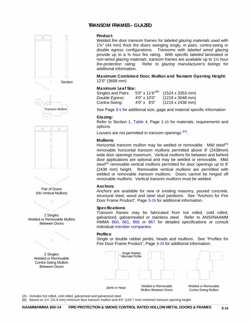
NAAMM/HMMA 850-14 FIRE-PROTECTION & SMOKE CONTROL RATED HOLLOW METAL DOORS & FRAMES
TRANSOM FRAMES - GLAZED
Product: Welded fire door transom frames for labeled glazing materials used with 1¾" (44 mm) thick fire doors swinging singly, in pairs, contra-swing or double egress configurations. Transoms with labeled wired glazing provide up to a ¾ hour fire rating. With specific labeled laminated or non-wired glazing materials, transom frames are available up to 1½ hour fire-protection rating. Refer to glazing manufacturer's listings for additional information.
Maximum Combined Door, Mullion and Transom Opening Height: 12'0" (3658 mm)
Maximum Leaf Size: Singles and Pairs: 5'0" x 11'6"(B) (1524 x 3353 mm) Double Egress: 4'0" x 10'0" (1219 x 3048 mm) Contra-Swing: 4'0" x 8'0" (1219 x 2438 mm)
See Page 3-5 for additional size, gage and material specific information
Glazing: Refer to Section 1, Table 4, Page 1-15 for materials, requirements and options.
Louvers are not permitted in transom openings [64].
Mullions: Horizontal transom mullion may be welded or removable. Mild steel(A) removable horizontal transom mullions permitted above 8' (2438mm) wide door openings maximum. Vertical mullions for between and behind door applications are optional and may be welded or removable. Mild steel(A) removable vertical mullions permitted for door openings up to 8' (2438 mm) height. Removable vertical mullions are permitted with welded or removable transom mullions. Doors cannot be hinged off removable mullions. Vertical transom mullions must be welded.
Anchors: Anchors are available for new or existing masonry, poured concrete, structural steel, wood and steel stud partitions. See "Anchors for Fire Door Frame Product", Page 3-29 for additional information.
Specifications: Transom frames may be fabricated from hot rolled, cold rolled, galvanized, galvannealed or stainless steel. Refer to ANSI/NAAMM HMMA 860, 861, 866 or 867 for detailed specifications or consult individual member companies.
Profiles: Single or double rabbet jambs, heads and mullions. See "Profiles for Fire Door Frame Product", Page 3-28 for additional information.
(A): Includes hot rolled, cold rolled, galvanneal and galvanized steel (B): Based on 1¼" (31.8 mm) minimum face transom mullion and 4¾" (120.7 mm) minimum transom opening height
Single RabbetAlternate Profile
Pair of Doors (No Vertical Mullion)
2 Singles Welded or Removable Mullion
Between Doors
2 Singles Welded or Removable Contra-Swing Mullion
Between Doors
Section
Welded or Removable Mullion Between Doors
Jamb or Head Welded or Removable Contra-Swing Mullion
Transom Mullion
3-19

NAAMM/HMMA 850-14 FIRE-PROTECTION & SMOKE CONTROL RATED HOLLOW METAL DOORS & FRAMES
MULTIPLE OPENING TRANSOM FRAMES - GLAZED OR PANELED
Product: 1½ hour (maximum) welded fire door transom frames with 1¾" (44.4 mm) thick welded or removable transom panels, steel-faced ⅜" to ¾" (9.5 to 19.1 mm) transom panels or specific labeled glazing materials, used with 1¾" (44 mm) thick fire doors, swinging in combinations of singles, pairs, contra-swing and/or double egress configurations. Transoms with labeled wired glazing provide up to a ¾ hour fire rating. With specific labeled laminated or non-wired glazing materials, multi-opening transom frames are available up to 1½ hour fire-protection rating. Refer to glazing manufacturer's listings for additional information.
Maximum Over-All Unit Size: (Width x Height) Drywall Partitions: 1½ Hr: 12'10" x 10'0" (3912 x 3048 mm) ¾ Hr: 12'10" x 11'4" (3912 x 3454 mm) All Other Partitions: 1½ Hr: 12'10" x 12'0" (3912 x 3658 mm) ¾ Hr: 13'6" x 12'0" (4115 x 3658 mm)
Maximum Door Opening: Singles and Contra-Swing: 4'0" x 8'0" (1219 x 2438 mm) Pairs and Double Egress: 8'0" x 8'0" (2438 x 2438 mm)
Maximum Leaf Size: 4'0" x 8'0" (1219 x 2438 mm)
Maximum Transom Panel Size: Singles and Contra-Swing: 4'0" x 4'0" (1219 x 1219 mm) Pairs and Double Egress: 8'0" x 4'0" (2438 x 1219 mm)
Transom Material: Minimum 0.032" (0.8 mm) thick hot rolled, cold rolled, galvanized, galvannealed or Type 430 stainless steel laminated to each face of an approved core.
Glazing: Refer to Section 1, Table 4, Page 1-15 for materials, requirements and options.
Louvers are not permitted in transom openings [64]. Mullions: Horizontal and vertical transom mullions may be welded or removable. Removable horizontal transom mullions permitted above 8' (2438mm) wide door openings maximum. Vertical mullions at doors may be welded or removable for either between or behind door applications. Removable vertical mullions permitted for door openings up to 8' (2438 mm) height. Removable vertical mullions are permitted with welded or removable transom mullions. Doors cannot be hinged off removable mullions.
Anchors: Anchors are available for new or existing masonry, poured concrete, structural steel, wood and steel stud partitions See "Anchors for Fire Door Frame Product", Page 3-29 for additional information.
Specifications: Frames may be fabricated from hot rolled, cold rolled, galvanized or galvannealed steel. Refer to ANSI/NAAMM HMMA 860, 861 or 867 for detailed specifications or consult individual member companies.
Profiles: Single or double rabbet jambs, heads and mullions. See "Profiles for Fire Door Frame Product", Page 3-28 for additional information.
Welded or Rem Mull
Between Doors
Jamb or Head
Welded or Rem Mull
Behind Doors
Welded or Rem Contra-Swing
Mullion
3-20

NAAMM/HMMA 850-14 FIRE-PROTECTION & SMOKE CONTROL RATED HOLLOW METAL DOORS & FRAMES
SIDELIGHT AND WINDOW FRAMES - GLAZED OR PANELED Notes: (A): Codes [3,6,7] may limit the maximum area and / or
percentage of wall length/area. (B): Includes hot rolled, cold rolled, galvanized and
galvanneal steel. (C): Maximum single glazed opening sizes indicated.
No vertical or horizontal mullions are permitted. Contact individual member manufacturers for detailed glazing and size information.
Product: Welded fire door frame with side panels and/or lights and optional transom panels and/or lights, used with 1¾" (44 mm) thick fire doors, swinging singly, in pairs, contra-swing or double egress configurations.
Welded or slip-on fire window frames with fixed openings and labeled glazing materials and/or panels. Fire windows may be mounted directly on the floor or on knee wall partitions.
Sidelights and windows with labeled wired glazing provide a maximum ¾ hour fire-protection rating. With specific labeled laminated or non-wired glazing materials and/or panels, sidelights and windows are available up to 1½ hour fire-protection rating. Refer to glazing manufacturer's listings for additional information.
Segmented mild(B) or 430 stainless steel sidelight and window frames, ¾ hour rating maximum, in all partition types may incorporate 2, 3 or 4-way vertical hollow metal corner posts.
Field splices are permitted in ¾ hour rated (maximum) sidelight and window frames and may be used in conjunction with vertical hollow metal corner posts and segmented units.
Maximum Over-All Unit Size(A): Mild(B) & Type 430 Stainless Steel: 13'6" x 12'0" (4115 x 3658 mm) Type 304 & 316 Stainless Steel: 9'4" x 10'0" (2845 x 3048 mm) Slip-On Windows(B,C): 7'11" x 7'11" (2413 x 2413 mm)
Individual 'segment lengths' (shown as * on the plan views at left) may not exceed the over-all unit widths defined above.(A)
Maximum Door Opening: Mild(B) and Type 430 Stainless Steel: Singles: 4'0" x 10'0" (1219 x 3048 mm) Pairs and Double Egress: 8'0" x 10'0" (2438 x 3048 mm) Contra-Swing: 8'0" x 8'0" (2438 x 2438 mm) Type 304 and 316 Stainless Steel: Singles and Contra-Swing: 4'0" x 8'0" (1219 x 2438 mm) Pairs and Double Egress: 8'0" x 8'0" (2438 x 2438 mm)
Maximum Leaf Size: Mild(B) and Type 430 Stainless Steel: Singles, Pairs and Double Egress: 4'0" x 10'0" (1219 x 3048 mm) Contra-Swing: 4'0" x 8'0" (1219 x 2438 mm) Type 304 and 316 Stainless Steel: Singles, Pairs, Double Egress and Contra-Swing: 4'0" x 8'0" (1219 x 2438 mm)
Maximum Individual Panel Size: Sidelight Frames: Transom: 8'0" x 4'0" (2438 x 1219 mm) Side: 8'0" width, 8'0" height, 4608 in2 area (2438 mm, 2438 mm, 2.97 m2) Window Frames: 8'0" width, 8'0" height, 4608 in2 area (2438 mm, 2438 mm, 2.97 m2)
See Page 3-6 for additional size, gage and material specific information
3-21
Floor Mounted Fire Window
Knee Wall Mounted Fire Window
*
*
*
*
*
*
*
*
*
* *
***
*

NAAMM/HMMA 850-14 FIRE-PROTECTION & SMOKE CONTROL RATED HOLLOW METAL DOORS & FRAMES
SIDELIGHT AND WINDOW FRAMES - GLAZED OR PANELED (continued)
Panel Material: Minimum 0.032" (0.8 mm) thick hot rolled, cold rolled, galvanized, galvannealed or stainless steel laminated to each face of an approved core.
Glazing: Refer to Section 1, Table 4, Page 1-15 for materials, requirements and options.
Louvers are not permitted, except in door openings [64]
Mullions: Vertical mullions for between the door applications are optional and may be welded or removable. Mild steel(B) removable vertical mullions permitted for door openings up to 8' (2438 mm) height. Removable vertical mullions are permitted with welded or removable transom mullions. Horizontal transom mullions (immediately above doors) may be welded or removable. Mild steel(B) removable horizontal mullion permitted above 8' (2438 mm) wide door openings maximum. All other mullions must be welded. Doors cannot be hinged off removable mullions. Anchors: Anchors are available for new or existing masonry, poured concrete, structural steel, wood and steel stud partitions. See "Anchors for Fire Door Frame Product", Page 3-29 for additional information. Specifications: Sidelight and window frames may be fabricated from hot rolled, cold rolled, galvanized, galvannealed or stainless steel. Refer to ANSI/NAAMM HMMA 860, 861, 866 or 867 for detailed specifications or consult individual member companies. Profiles: Single or double rabbet jambs, heads, mullions, sills and corner posts. Mullions (not surrounding doors) center rails and sills may be recessed from perimeter members. See "Profiles for Fire Door Frame Product", Page 3-28 for additional information.
3-22
Jambs and Heads
Mullions and Center Rails
Sills
Typical Vertical Hollow Metal Corner Posts for Sidelight and Window Frames

NAAMM/HMMA 850-14 FIRE-PROTECTION & SMOKE CONTROL RATED HOLLOW METAL DOORS & FRAMES
SOUND CONTROL HOLLOW METAL DOOR AND FRAME ASSEMBLIES
Product: 3 hour (maximum) sound control fire door and frame assembly with 1¾" (44 mm) (minimum) thick doors, swinging singly or in pairs. Doors, frame and sound seals must be provided as a complete assembly.
Assemblies are rated for Sound Transmission Class (STC), Outdoor-Indoor Transmission Class (OITC) or Sound Transmission Loss (STL). Air borne sound transmission loss is measured in accordance with ASTM E90. The STC is determined by the procedures set forth in ASTM E413 or the OITC by those in ASTM E1332.
Maximum Door Opening: Singles: 4'0" x 8'0" (1219 x 2438 mm) Pairs: 8'0" x 8'0" (2438 x 2438 mm)
Maximum Leaf Size: 4'0" x 8'0" (1219 x 2438 mm)
Hardware: Consult individual member companies for details
Glazing: 3 hour: Glazing not permitted 1½ hour: 100 in2 (0.065m2) glass light per leaf ¾ hour: 300 in2 (0.194m2) glass light per leaf
Contact individual member companies for additional details
Mullions: Welded mullions for between the door applications are optional.
Anchors: Anchors are available for new or existing masonry, poured concrete, structural steel, wood and steel stud partitions. See "Anchors for Fire Door Frame Product", Page 3-29 for additional information.
Specifications: Assemblies may be fabricated from hot rolled, cold rolled, galvanized or galvannealed steel. Refer to ANSI/NAAMM HMMA 865 for detailed specifications or consult individual member companies.
Profiles: Cased open, single or double rabbet jambs, heads and mullions with applied adjustable gasketing. See "Profiles for Fire Door Frame Product", Page 3-28 for additional information.
Pair of Doors (No Vertical Mullion)
2 Singles Welded Mullion Between Doors
AdjustableGasket
Single Rabbet Alternate Profile
Jamb or Head Detail (Gasketing varies with manufacturer)
Door Bottom Detail (Varies with manufacturer)
3-23

NAAMM/HMMA 850-14 FIRE-PROTECTION & SMOKE CONTROL RATED HOLLOW METAL DOORS & FRAMES
COMMERCIAL SECURITY HOLLOW METAL DOOR AND FRAME ASSEMBLIES
Product: 3 hour (maximum) commercial security fire door and frame assembly with 1¾" (44 mm) (minimum) thick doors, swinging singly or in pairs or sliding singly, for use in facilities where a high degree of security is required. Commercial security assemblies must comply with one or more of the test procedures in ASTM F1450, ASTM F1592, SD-STD-01.01 Rev. G (1993) or LPS 1175: Issue 5 (2000), and the acceptance criteria of ANSI/NAAMM HMMA 862. In addition these products are available with bullet-resistant capabilities meeting ANSI/UL 752.
Maximum Door Opening: Singles - Swinging or Sliding: 4'0" x 8'0" (1219 x 2438 mm) Pairs - Swinging: 8'0" x 8'0" (2438 x 2438 mm)
Maximum Leaf Size: 4'0" x 8'0" (1219 x 2438 mm)
Hardware: Consult individual member companies for details
Glazing: Consult individual member companies for details
Mullions: Welded mullions for between the door applications are optional.
Anchors: Anchors are available for new or existing masonry or poured concrete partitions. See "Anchors for Fire Door Frame Product", Page 3-29 for additional information.
Specifications: Assemblies may be fabricated from hot rolled, cold rolled, galvanized, galvannealed or stainless steel. Refer to ANSI/NAAMM HMMA 862 for detailed specifications or consult individual member companies.
Profiles: Single and double rabbet jambs, heads and mullions. See "Profiles for Fire Door Frame Product", Page 3-28 for additional information.
Door Mounted Lock Strike Jamb, Hinge
Jamb or Head Welded Mullion Between Doors
Single Rabbet Alternate Profile
Jamb Mounted Lock Strike Jamb
3-24
Pair of Doors (No Vertical Mullion)
2 Singles Welded Mullion Between Doors

NAAMM/HMMA 850-14 FIRE-PROTECTION & SMOKE CONTROL RATED HOLLOW METAL DOORS & FRAMES
DETENTION SECURITY HOLLOW METAL DOOR AND FRAME ASSEMBLIES
Product: 3 hour (maximum) detention security fire door and frame assembly with 2" (50.8 mm) (minimum) thick doors, swinging singly or in pairs or sliding singly, for use in detention and correctional facilities and other buildings where a high degree of security is required. Detention security assemblies must comply with ASTM F1450 and ASTM F1592 test procedures and the acceptance criteria of ANSI/NAAMM HMMA 863 for impact resistance, static load, rack, edge crush and removable glazing stop requirements. In addition these products are available with bullet-resistant capabilities meeting ANSI/UL 752.
Maximum Door Opening: Singles - Swinging or Sliding: 4'0" x 8'0" (1219 x 2438 mm) Pairs - Swinging: 8'0" x 8'0" (2438 x 2438 mm)
Maximum Leaf Size: 4'0" x 8'0" (1219 x 2438 mm)
Hardware: Consult individual member companies for details
Glazing: Refer to Section 1, Table 3, Page 1-14 for door requirements and options.
Mullions: Welded mullions for between the door applications are optional.
Anchors: Anchors are available for new or existing masonry or poured concrete partitions. See "Anchors for Fire Door Frame Product", Page 3-29 for additional information.
Specifications: Assemblies may be fabricated from hot rolled, cold rolled, galvanized, galvannealed or stainless steel. Refer to ANSI/NAAMM HMMA 863 for detailed specifications or consult individual member companies.
Profiles: Single and double rabbet jambs, heads and mullions. See "Profiles for Fire Door Frame Product", Page 3-28 for additional information.
3-25
Single Jamb Mounted Lock
Pair of Doors (No Mullion)
Door Mounted Lock
2 Singles Welded Mullion Between Doors
Door Mounted Lock
Door Mounted Lock Strike Jamb, Hinge
Jamb or Head
Welded Mullion Between Doors
Jamb Mounted Lock Strike Jamb
Single Rabbet Alternate Profile
Single Door Mounted Lock
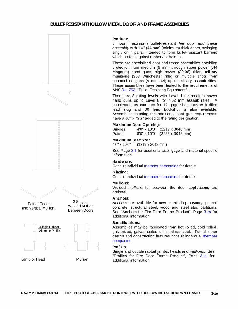
NAAMM/HMMA 850-14 FIRE-PROTECTION & SMOKE CONTROL RATED HOLLOW METAL DOORS & FRAMES
BULLET-RESISTANT HOLLOW METAL DOOR AND FRAME ASSEMBLIES
Product: 3 hour (maximum) bullet-resistant fire door and frame assembly with 1¾" (44 mm) (minimum) thick doors, swinging singly or in pairs, intended to form bullet-resistant barriers which protect against robbery or holdup.
These are specialized door and frame assemblies providing protection from medium (9 mm) through super power (.44 Magnum) hand guns, high power (30-06) rifles, military munitions (308 Winchester rifle) or multiple shots from submachine guns (9 mm Uzi) up to military assault rifles. These assemblies have been tested to the requirements of ANSI/UL 752, "Bullet-Resisting Equipment".
There are 8 rating levels with Level 1 for medium power hand guns up to Level 8 for 7.62 mm assault rifles. A supplementary category for 12 gage shot guns with rifled lead slug and 00 lead buckshot is also available. Assemblies meeting the additional shot gun requirements have a suffix "SG" added to the rating designation.
Maximum Door Opening: Singles: 4'0" x 10'0" (1219 x 3048 mm) Pairs: 8'0" x 10'0" (2438 x 3048 mm)
Maximum Leaf Size: 4'0" x 10'0" (1219 x 3048 mm)
See Page 3-6 for additional size, gage and material specific information Hardware: Consult individual member companies for details Glazing: Consult individual member companies for details
Mullions: Welded mullions for between the door applications are optional.
Anchors: Anchors are available for new or existing masonry, poured concrete, structural steel, wood and steel stud partitions. See "Anchors for Fire Door Frame Product", Page 3-29 for additional information.
Specifications: Assemblies may be fabricated from hot rolled, cold rolled, galvanized, galvannealed or stainless steel. For all other design and construction features consult individual member companies.
Profiles: Single and double rabbet jambs, heads and mullions. See "Profiles for Fire Door Frame Product", Page 3-28 for additional information.
Pair of Doors (No Vertical Mullion)
2 Singles Welded Mullion Between Doors
Jamb or Head Mullion
Single Rabbet Alternate Profile
3-26

NAAMM/HMMA 850-14 FIRE-PROTECTION & SMOKE CONTROL RATED HOLLOW METAL DOORS & FRAMES
RADIATION SHIELDING HOLLOW METAL DOOR AND FRAME ASSEMBLIES
Product: 3 hour (maximum) radiation shielding door and frame assembly with 1¾" (44 mm) thick doors swinging singly or in pairs used to provide shielding against x-rays and other forms of radiation which could be injurious to humans, other forms of life or material.
These assemblies are designed to specification to provide shielding against specific types and intensities of radiation. Maximum Door Opening: Singles: 4'0" x 8'0" (1219 x 2438 mm) Pairs: 8'0" x 8'0" (2438 x 2438 mm) Maximum Leaf Size: 4'0" x 8'0" (1219 x 2438 mm) Hardware: Consult individual member companies for details Glazing: Refer to Section 1, Table 3, Page 1-14 for requirements. Mullions: Welded mullions for between the door applications are optional. Anchors: Anchors are available for new or existing masonry, poured concrete, structural steel, wood and steel stud partitions. See "Anchors for Fire Door Frame Product", Page 3-29 for additional information. Specifications: Assemblies may be fabricated from hot rolled, cold rolled, galvanized, galvannealed or stainless steel. For all other design and construction features consult individual member companies. Profiles: Single or double rabbet jambs, heads and mullions. See "Profiles for Fire Door Frame Product", Page 3-28 for additional information.
Pair of Doors (No Vertical Mullion)
2 Singles Welded Mullion Between Doors
Sheet LeadLining
Single RabbetAlternate Profile
Jamb or Head
3-27
Mullion
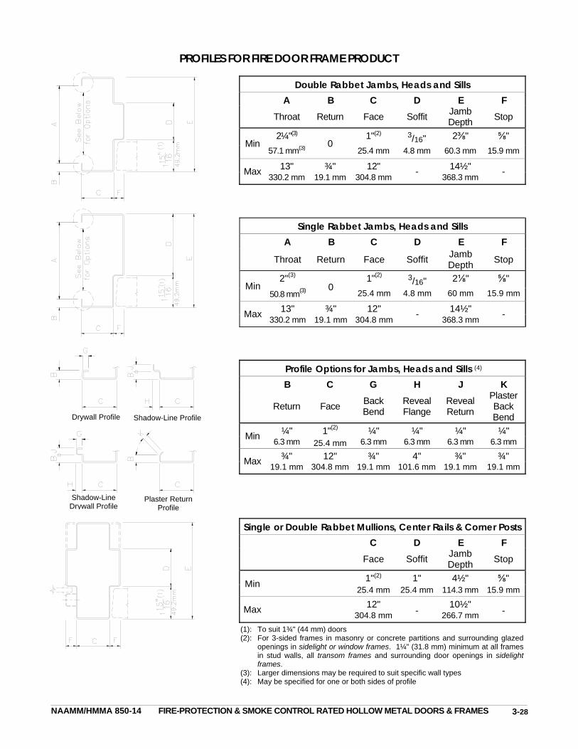
NAAMM/HMMA 850-14 FIRE-PROTECTION & SMOKE CONTROL RATED HOLLOW METAL DOORS & FRAMES
PROFILES FOR FIRE DOOR FRAME PRODUCT
Double Rabbet Jambs, Heads and Sills A B C D E F
Throat Return Face Soffit Jamb Depth
Stop
Min2¼"(3)
0 1"(2) 3/16" 2⅜" ⅝"
57.1 mm(3) 25.4 mm 4.8 mm 60.3 mm 15.9 mm
Max 13" ¾" 12" - 14½" - 330.2 mm 19.1 mm 304.8 mm 368.3 mm
Single Rabbet Jambs, Heads and Sills A B C D E F
Throat Return Face Soffit Jamb Depth
Stop
Min 2"(3)
0 1"(2) 3/16" 2⅛" ⅝"
50.8 mm(3) 25.4 mm 4.8 mm 60 mm 15.9 mm
Max 13" ¾" 12" - 14½" - 330.2 mm 19.1 mm 304.8 mm 368.3 mm
Profile Options for Jambs, Heads and Sills (4) B C G H J K
Return Face Back Bend
Reveal Flange
Reveal Return
Plaster Back Bend
Min ¼" 1"(2) 25.4 mm
¼" ¼" ¼" ¼" 6.3 mm 6.3 mm 6.3 mm 6.3 mm 6.3 mm
Max ¾" 12" ¾" 4" ¾" ¾" 19.1 mm 304.8 mm 19.1 mm 101.6 mm 19.1 mm 19.1 mm
Single or Double Rabbet Mullions, Center Rails & Corner Posts C D E F
Face Soffit Jamb Depth
Stop
Min 1"(2) 1" 4½" ⅝" 25.4 mm 25.4 mm 114.3 mm 15.9 mm
Max 12"
- 10½"
- 304.8 mm 266.7 mm
(1): To suit 1¾" (44 mm) doors (2): For 3-sided frames in masonry or concrete partitions and surrounding glazed
openings in sidelight or window frames. 1¼" (31.8 mm) minimum at all frames in stud walls, all transom frames and surrounding door openings in sidelight frames.
(3): Larger dimensions may be required to suit specific wall types (4): May be specified for one or both sides of profile
Drywall Profile Shadow-Line Profile
Plaster Return Profile
Shadow-Line Drywall Profile
3-28

NAAMM/HMMA 850-14 FIRE-PROTECTION & SMOKE CONTROL RATED HOLLOW METAL DOORS & FRAMES
ANCHORS FOR FIRE DOOR FRAME PRODUCT Wall Anchors - General: Each jamb of the frame product must be provided with anchors to suit the wall construction to which the jamb is to be fastened. Jambs in the same frame product may be provided with anchors to suit different wall types (ie: unit masonry at one, steel stud partition at the other). Frame product can only be anchored to a wall and may not be anchored to an adjacent frame product, glazed block assembly, wall grille, diffuser or louver [55,85].
All anchors used in the installation of fire-protection rated frame product must be included in the Follow-Up Service (FUS) procedures or Factory Audit Manuals (FAM) of the original product manufacturer, as approved and issued by the certifier.
Each anchor is located immediately above or below the hinge reinforcing on the hinge jamb and directly opposite on the strike jamb as shown in Figure 6.
Unless listed otherwise welded and knocked-down fire-protection rated frame products require two anchors for each jamb up to 5'0" (1524 mm) and an additional anchor for each additional 2'6" (762 mm) of height or fraction thereof.
Grout, when used in accordance with industry guidelines, may improve frame durability, sound deadening and, depending on wall construction, increase frame anchorage strength. Grouting a frame does not increase door durability and is not required to maintain the fire-protection rating of frame product. For most commercial applications grouting of mullions, other closed sections and frames in wood or steel stud partitions is not recommended. See HMMA's Tech Note, "Grouting Hollow Metal Frames", HMMA-820 TN01-03, for additional information.
For welded and knocked-down frame product in stud partitions HMMA recommends that one additional anchor be provided for each jamb over the number of anchors required for masonry openings of equivalent height.
Approved anchors similar to those shown on these pages, HMMA 840, "Guide Specifications for Installation and Storage of Hollow Metal Doors and Frames" and referenced in NAAMM-HMMA's 860 Series Guide Specifications, may be used with fire-protection rated frame product.
Masonry Anchors: Figures 7A, 7B and 7C illustrate masonry anchors approved for welded and knocked-down fire-protection rated frame product. The stirrup of the Strap and Stirrup type is welded to the back of the jamb soffit. This type of anchor can be used in either masonry or poured concrete construction. The T-Strap and Wire Loop types are shipped loose. Each type provides sufficient adjustment for masonry coursing as well as access for full grouting of jambs. These anchors are eligible for use in frame product rated up to 3 hours.
STRAP AND STIRRUP ANCHOR T-STRAP ANCHOR WIRE LOOP ANCHOR FIGURE 7A FIGURE 7B FIGURE 7C
SINGLE UNIT TYPE PRESSED STEEL FRAME FIGURE 6
CLOSER REINF.HEAD PIECE
HINGE JAMB
ANCHOR
HINGE REINF.
BASEANCHOR
STRIKEJAMB
STRIKEREINF.
HEAD
WALL ANCHOR
FLOOR ANCHOR
3-29

NAAMM/HMMA 850-14 FIRE-PROTECTION & SMOKE CONTROL RATED HOLLOW METAL DOORS & FRAMES
Steel Stud Anchors: Figure 8A illustrates a steel stud anchor which is welded to the back of the jamb and attached to the steel stud by welding or mechanical fasteners. Figure 8B shows a steel stud anchor which may be welded or friction fitted inside the jamb profile. Both are eligible for use in welded and knocked-down frames up to 3 hour rating. Figures 8C and 8D are for welded frame product up to 1½ hour rating, end-butted in steel stud partitions. Figure 8C illustrates new steel stud partition applications, and Figure 8D, existing partitions. For new steel stud applications (Figure 8C) anchors are welded to the back of each jamb 6" (152 mm) from each end and at 24" (610 mm) on center (maximum) and secured to the stud by welding or mechanical fasteners. For existing steel stud installations (Figure 8D) anchors are welded in jambs and heads pierced and dimpled for ¼" (6 mm) diameter sheet metal screws not more than 6" (152 mm) from each end and 24" (610 mm) on center maximum.
Z-SHAPED STEEL COMBINATION WOOD BUTTED TO NEW STEEL BUTTED TO EXISTING STEEL STUD ANCHORS OR STEEL STUD ANCHORS STUD & GYPSUM BOARD STUD & GYPSUM BOARD FIGURE 8A FIGURE 8B FIGURE 8C FIGURE 8D For 1½ hour rated slip-on construction frames in wood or steel stud partitions Figure 9A illustrates the typical adjustable compression type anchor welded near the top of each jamb. Figures 9B and 9C illustrate typical base anchor types used in conjunction with the compression anchors in Figure 9A. Figure 9B, the strap type, is welded or friction fitted into the bottom of each jamb face. As an alternate each face can be provided with dimpled holes as shown in Figure 9C. In both cases the bottom of the frame is secured with nails or screws through the holes in the anchor or jamb face into the drywall board and the wood or steel floor runner. NFPA 80 [58] requires frame installation in accordance with the instructions provided by the manufacturer for this frame construction. Wood Stud Anchors: Figures 10A and 10B illustrate wood stud anchors which are welded to the back of the jamb and attached to the wood studs with fasteners through holes in the anchor. These anchors are eligible for use in welded and knocked-down frame product up to 1½ hour rating.
COMPRESSION ANCHOR FIGURE 9A
STRAP TYPE FIGURE 9B
FACE DIMPLED TYPE FIGURE 9C
1-PC WOOD STUD ANCHOR
FIGURE 10A
2-PC WOOD STUD ANCHOR
FIGURE 10B
3-30

NAAMM/HMMA 850-14 FIRE-PROTECTION & SMOKE CONTROL RATED HOLLOW METAL DOORS & FRAMES
The anchor illustrated in Figure 8B can also be used for wood stud wrap applications. The anchors shown in Figure 11 can be used for end-butt in wood stud partitions. Jamb and head soffits are pierced and dimpled for ¼" (6 mm) diameter sheet metal screws not more than 6" (152 mm) from each end and at 24" (610 mm) on center maximum is also permitted for welded frame product up to 1½ hour rating. Wood screws replace the screws or expansion bolts.
Existing Masonry Wall Anchors: Figure 11 illustrates existing masonry or concrete anchor preparations. The frame is anchored in prepared openings by means of flat head bolts and expansion shells or self-drilling concrete screws. Anchors of this type are located not more than 6" (152 mm) from the top and bottom of each jamb with intermediate anchors equally spaced at a maximum of 26" (660 mm) on center. These anchors are eligible for use in welded and knocked-down frame product up to 3 hour rating. Floor Anchors: Figure 12A illustrates a welded floor anchor and Figure 12B shows an adjustable type floor anchor, each for use in welded or knocked-down frame product. These anchors are welded to the inside of each jamb. Floor anchors are not required for two-section type frames with a pressed-steel rough buck, nor are they required for frames provided with existing wall anchors. For other applications which do not permit the use of a floor anchor, substitution with an additional wall anchor not more than 8" (204 mm) from the base of the jamb is permitted. Figures 13A and 13B illustrate typical floor anchors provided for welded and removable mullions. Each is provided loose and is secured to the floor with mechanical fasteners.
EXISTING MASONRY WALL ANCHORS FIGURE 11
WELDED FLOOR ANCHOR
FIGURE 12A
ADJUSTABLE FLOOR ANCHOR
FIGURE 12B
3-31
WELDED MULLION FIGURE 13A
REMOVABLE MULLION FIGURE 13B

NAAMM/HMMA 850-14 FIRE-PROTECTION & SMOKE CONTROL RATED HOLLOW METAL DOORS & FRAMES
OTHER DESIGN LIMITATIONS FOR FIRE DOOR AND FRAME PRODUCT Due to hardware limitations, code or other regulatory requirements the following are not available as fire-protection rated product: - Sloped, round or arch top doors - TRR doors in transom or sidelight frames - Glazing materials in louvered doors - Fire door louvers in; - ⅓ hr doors - Doors in a means of egress - Smoke control doors - Double egress doors - TRR doors - Sound control doors - Lead-lined doors - Bullet-resistant doors - Cylindrical locks or fire exit hardware on doors exceeding 10' (3048 mm) height - Open back strikes on pairs of 3 hour doors - Non-labeled facings, claddings or finishes (wood veneer, plastic, paper or fabric, stone or mirrors) - Radiused or bull-nosed lock edge doors - Rabetted hinge edge doors - Mail slots - Mono rail cutouts - Double acting doors - Thermally broken frame product - KD sidelights assemblies - Slip-on transom or sidelight frames - Doors hinged off removable vertical hollow metal mullions - Removable vertical hollow metal mullions in 3 hour frame product - Installations in ceilings or floors
3-32

NAAMM/HMMA 850-14 FIRE-PROTECTION & SMOKE CONTROL RATED HOLLOW METAL DOORS & FRAMES
SECTION 4
REFERENCE AND SUPPORT MATERIALS
CONTENTS Footnote References 2012 IBC ....................................................... 4-2 NFPA 80-2010 .............................................. 4-2
Reference Standards ......................................... 4-3
Corresponding US and Canadian Standards .......................................... 4-4
Fire Door Labels for US and/or Canadian Code Compliance .............................. 4-4
Code or Standard Defined Terms ...................... 4-5
Abbreviations ..................................................... 4-5
3-264-1

NAAMM/HMMA 850-14 FIRE-PROTECTION & SMOKE CONTROL RATED HOLLOW METAL DOORS & FRAMES
Footnote References As indicated in the Foreword, on the publication date of this document, 2012 was the most recently adopted edition of the International Building Code and is the base model code reference standard for the information presented herein. 2010 is the NFPA 80 edition referenced in the 2012 IBC for the installation of fire door and window assemblies.
In order to assist readers in determining the requirements in earlier editions of the IBC and NFPA 80 (which remain in force in many jurisdictions) and future editions of either, the following lists the Chapter-Section and Title/Topics footnoted in NAAMM-HMMA 850-14. For reference purposes, the following details the edition of NFPA 80 referenced in each IBC;
IBC Edition: 2000 2003 2006 2009 2012 NFPA 80 Reference: 1999 1999 1999 2007 2010
IBC-2012 Foot Chapter Foot Chapter Note -Section Title or Topic Note -Section Title or Topic 1 407.3.1 ........ Corridor Doors 2 407.5 ........... Smoke Barriers 3 408.3.8 ........ Interior Stairs and Ramps, Glazing 4 509.4.2 ........ Incidental Uses, Protection 5 703.6 ........... Fire-Resistance Rated Glazing 6 706.8 ........... Fire Walls, Openings 7 707.6 ........... Fire Barriers, Openings 8 708.6 ........... Fire Partitions, Openings 9 709.5 ........... Smoke Barriers, Openings 10 710.3 ........... Smoke Partitions, Fire Resistance Ratings 11 710.5 ........... Smoke Partitions, Openings 12 716.2 ........... Opening Protectives, Fire- Resistance Rated Glazing
13 716.3 ........... Opening Protectives, Marking Fire-Rated Glazing Materials 14 716.5 ........... Fire Door Assemblies 15 716.5.3 ........ Smoke Barriers, Smoke and Draft Control Doors 16 716.5.5 ........ Interior Exit Stairways and Exit Passageway Doors 17 716.5.6 ........ Fire Door Frames with Transom Lights and Sidelights 18 716.5.7 ........ Labeled Protective Assemblies 19 716.5.8 ........ Glazing Materials 20 716.5.9 ........ Door Closing 21 716.6 ........... Fire-Protection Rated Glazing, Fire Windows 22 1703 ............ Approvals 23 2406 ............ Safety Glazing
NFPA 80-2010 24 3.3.85 .......... Lintel (definition) 25 4.1.3 ............ Appurtenances 26 4.1.3.1 ......... Preparations for Hardware 27 4.2 ............... Labels 28 4.2.2 ............ Label Location 29 4.3.3 ............ Fire Exit Hardware 30 4.3.5 ............ Label Text (FED) 31 4.4.1 ............ Glazing - FRR or FPR 32 4.4.2 ............ Glazing - Safety Standards 33 4.4.5 ............ Glazing - Installation in Doors 34 4.4.6 ............ Glazing - Labeling 35 4.4.7 ............ Door Viewers 36 4.5 ............... Fire-Resistance Rated Glazing 37 4.6.2 ............ Hardware for Doors 38 4.6.3 ............ Builders Hardware 39 4.6.3.1 ......... Builders Hardware - Types 40 4.6.3.2 ......... Builders Hardware - Installation 41 4.6.3.3 ......... Fire Exit Hardware 42 4.8.4 ............ Clearance 43 4.8.5.2 ......... Combustible Floor Coverings 44 4.9 ............... Fire Testing 45 5.1.3.1 ......... Operability 46 5.1.5.1 ......... Repairs 47 5.1.5.2 ......... Field Modifications 48 5.2 ............... Inspections 49 5.2.15 .......... Repairs 50 6.1.3 ............ Installation of Swinging Doors 51 6.1.4 ............ Operation 52 6.1.4.3 ......... Automatic Closing Doors 53 6.1.4.4 ......... Power operated Doors 54 6.2.1.1 ......... Frames - Non-Load Bearing 55 6.2.1.2 ......... Wall Anchorage 56 6.2.3 ............ Lintels
57 6.3.1.1 ......... Labeled Frames 58 6.3.1.4 ......... Slip-On Frame Installation Instructions 59 6.3.1.7 ......... Clearances 60 6.3.3.2 ......... Field Splicing 61 6.3.3.3 ......... Glazed Frame Product - FPR 62 6.3.3.4 ......... Glazed Frame Product - FRR 63 6.3.3.5 ......... Labeled Glazing 64 6.3.4.4 ......... Louvers in Frames 65 6.3.5.1 ......... Multi-Opening Frames - Sizes 66 6.4.1 ............ Closing Devices 67 6.4.1.1 ......... Closers 68 6.4.1.2 ......... Coordinators 69 6.4.3.1 ......... Hinges 70 6.4.4 ............ Locks or Latches 71 6.4.4.2 ......... Fire Exit Hardware 72 6.4.4.3 ......... Active Latch Bolts 73 6.4.4.4 ......... Fire Exit Hardware 74 6.4.4.4.1 ...... FEH and Open Back Strikes 75 6.4.4.5 ......... Pairs with Self-Latching Bolts 76 6.4.4.5.1 ...... Pairs with Manual Bolts 77 6.4.4.10 ....... Open Back Strikes 78 6.4.4.11 ....... Electric Strikes 79 6.4.5 ............ Protection Plates 80 6.4.6 ............ Automatic Louvers 81 6.4.7 ............ Astragals 82 6.4.8 ............ Gaskets 83 17.2.1 .......... Glazing Material - Labeled 84 17.2.4 .......... Glazing Material - Safety Rating 85 17.4.1 .......... Frame Installation 86 A.6.3.1.1 ..... Frame Labels - Hourly Rating 87 A.6.4.1.1 ..... Self-Closing Devices
4-2

NAAMM/HMMA 850-14 FIRE-PROTECTION & SMOKE CONTROL RATED HOLLOW METAL DOORS & FRAMES
Reference Standards
STANDARD TEST METHOD FOR LABORATORY MEASUREMENT OF AIRBORNE SOUND TRANSMISSION LOSS OF BUILDING PARTITIONS AND ELEMENTS, ASTM E 90
STANDARD TEST METHODS OF FIRE TESTS OF BUILDING CONSTRUCTION AND MATERIALS, ASTM E 119
CLASSIFICATION FOR RATING SOUND INSULATION, ASTM E 413
STANDARD TEST METHODS FOR HOLLOW METAL SWINGING DOOR ASSEMBLIES FOR DETENTION FACILITIES, ASTM F 1450
STANDARD TEST METHODS FOR DETENTION HOLLOW METAL VISION SYSTEMS, ASTM F 1592 American Society for Testing & Materials 100 Barr Harbor Drive West Conshohocken, PA 19428-2959 Telephone : (610) 832-9585 E-mail : [email protected] Website : http://www.astm.org BUTTS AND HINGES, ANSI/BHMA A156.1 DOOR CONTROL-CLOSERS, ANSI/BHMA A156.4
Builders Hardware Manufacturers Association 355 Lexington Avenue 15th Floor New York City, NY 10017 Telephone : (800) 699-9277 Website : http://www.buildershardware.com THE APPROVAL GUIDE
Factory Mutual Engineering & Research Corporation 1151 Boston-Providence Turnpike Norwood, MA 02062 Telephone : (617) 255-4682 Website : http://www.fmglobal.com INTERNATIONAL BUILDING CODE, 2012
International Code Council 500 New Jersey Avenue, NW 6th Floor Washington, DC 20001 Telephone : (800) 756-4452 Website : http://www.iccsafe.org WHI (ON-LINE) DIRECTORY OF LISTED PRODUCTS Intertek Testing Service NA, Inc. 545 East Algonquin Road, Suite F Arlington Heights, IL 60005 Telephone : (855) 944-2378 E-mail : [email protected] Website : http://www.intertek.com
HOLLOW METAL MANUAL
National Association of Architectural Metal Manufacturers 800 Roosevelt Road, Building C, Suite 312 Glen Ellyn, IL 60137 Telephone: (630) 942-6591 E-mail : [email protected] Website : http://www.naamm.org
STANDARD FOR FIRE DOORS AND OTHER OPENING PROTECTIVES, ANSI/NFPA 80 STANDARD FOR THE INSTALLATION OF SMOKE DOOR ASSEMBLIES AND OTHER OPENING PROTECTIVES, NFPA 105 STANDARD METHODS OF FIRE TESTS OF DOOR ASSEMBLIES, ANSI/NFPA 252
STANDARD ON FIRE TEST FOR WINDOW AND GLASS BLOCK ASSEMBLIES, ANSI/NFPA 257 National Fire Protection Association One Batterymarch Park P.O. Box 9101 Quincy, MA 02269-9101 Telephone : (617) 770-3000 E-mail : [email protected] Website : http://www.nfpa.org
STANDARD FOR FIRE TESTS OF WINDOW ASSEMBLIES, ANSI/UL 9
STANDARD FOR POSITIVE PRESSURE FIRE TESTS OF DOOR ASSEMBLIES, ANSI/UL 10C OUTLINE OF INVESTIGATION FOR FIRE DOOR FRAMES, UL 63 STANDARD FOR FIRE TESTS OF BUILDING CONSTRUCTION AND MATERIALS, ANSI/UL 263
STANDARD FOR BULLET-RESISTING EQUIPMENT, ANSI/UL 752 STANDARD FOR AIR LEAKAGE TESTS OF DOOR ASSEMBLIES, ANSI/UL 1784 UL (ON-LINE) FIRE RESISTANCE DIRECTORY UL, LLC 333 Pfingsten Road Northbrook, IL 60612 Telephone : (847) 272-8800 E-mail : [email protected] Website : http://www.ul.com SAFETY STANDARD FOR ARCHITECTURAL GLAZING MATERIALS, CPSC 16 CFR 1201
US Government Bookstore National Archives and Records Administration Office of the Federal Register 710 North Capitol Street N.W. Washington, DC Telephone : (800) 512-1800 Website : http://www.bookstore.gpo.gov
4-3

NAAMM/HMMA 850-14 FIRE-PROTECTION & SMOKE CONTROL RATED HOLLOW METAL DOORS & FRAMES
Corresponding US and Canadian Standards Many HMMA member manufacturers provide fire-protection rated products for both the US and Canadian markets. Although the fire tests are similar they are not identical. Compliance with one country's standards does not necessarily provide approval within the other.
The Canadian model code, the National Building Code of Canada (NBCC), mandates neutral pressure protocols, hose stream testing of all fire-protection rated components, is both performance and objective based and the "pass/fail" criteria for fire door assemblies differ slightly. The NBCC is more restrictive with respect to exclusions when active protection systems are utilized.
As stated in the Foreword the scope of this manual is limited to the requirements in the United States. However, for reference purposes, Table 6 provides the corresponding US and Canadian code mandated fire test and related standards.
Standard United States Canada
Model Building Code International Building Code - 2012
National Building Code of Canada - 2010
Fire Door Assembly Tests ANSI/UL 10C-09 or ANSI/NFPA 252-2008 CAN/ULC-S104-10
Fire Door Frame and Transom Frame Design UL Subject 63-03 CAN/ULC-S105-09
Fire Window Assembly Tests
ANSI/UL 9-09 or ANSI/NFPA 257-2007 CAN4-S106-M80(R1985)
Fire Door and Window Assembly Installation ANSI/NFPA 80-2010 ANSI/NFPA-80-2007
Smoke Control Tests ANSI/UL 1784-01 Not Applicable Smoke Control
Assembly Installation ANSI/NFPA 105-2010 Not Applicable
Wall Assembly Fire Tests
ANSI/UL 263-11 or ASTM E119-12 CAN/ULC-S101-07
Safety Glazing Tests CPSC 16 CFR 1201 Not Applicable
CORRESPODING US AND CANADIAN STANDARDS TABLE 6
Fire Door Labels for US and/or Canadian Code Compliance UL and WHI/ITS test, certify and list fire-protection rated products to the fire test standards of both countries. To identify such products they have adopted similar marking systems. The Figures below illustrate the basic fire door label content to indicate compliance with various UL and/or Canadian code requirements.
1. To show compliance with US positive pressure (UL 10C), US (legacy) neutral pressure (UL 10B) and the Canadian (S104) code requirements the label must include "UL 10C", a "cXXus" logo, reference to "Installation Instructions" and "Temp Rise Rating", as in Figure 12.
2. For US neutral pressure compliance only (UL 10B) the label will not include any reference to "UL 10C" or a "cXXus" logo as shown in Figure 13. The "S" symbol, "Installation Instructions" and "Temp Rise Exceeds" are not required but may be included.
3. When compliant with the US neutral pressure (UL 10B) and the Canadian (S104) code requirements only the label will have a "cXXus" logo without a reference to "UL 10C", as in Figure 14. The "S" symbol, "Installation Instructions" and "Temp Rise Exceeds" references are not required but may be included.
4. For product compliant with the Canadian (S104) requirements only a "cXX" logo will be present as in Figure 15. There will be no reference to "UL 10C". The "S" symbol, "Installation Instructions" and "Temp Rise Exceeds" are not required.
FIGURE 12 (Ref Item 1)
LISTED FIRE DOOR WHI-
POSITIVE PRESSURE TO UL 10C/NFPA MIN LATCH THROW-SINGLES: 1/2", PAIRS: 3/4"
TEMP RISE EXCEEDS 30 MIN. - 450°F/250°CSEE INSTALLATION INSTRUCTIONS S
4-4
FIGURE 13 (Ref Item 2)
FIGURE 14 (Ref Item 3)
FIGURE 15 (Ref Item 4)
HOUR RATING
DO NOT REMOVE OR COVER LABELIntertek
US
C
LISTED FIRE DOOR
WHI-
MIN LATCH THROW-SINGLES: 1/2", PAIRS: 3/4"
HOUR RATING
DO NOT REMOVE OR COVER LABELIntertek
W/N: XXXXX
W/N: XXXXX
LISTED FIRE DOOR
WHI-
MIN LATCH THROW-SINGLES: 1/2", PAIRS: 3/4"
HOUR RATING
DO NOT REMOVE OR COVER LABELIntertek
US
C
W/N: XXXXX
LISTED FIRE DOOR
WHI-
MIN LATCH THROW-SINGLES: 1/2", PAIRS: 3/4"
HOUR RATING
DO NOT REMOVE OR COVER LABELIntertek
C
W/N: XXXXX
UNDERWRITERS LABORATORIES INC.®CLASSIFIED
MIN LATCH THROW: SEE INSTALLATION INSTRUCTIONS TEMP RISE EXCEEDS 30 MIN - 450°F/250°C
SWINGING TYPE FIRE DOOR - UL 10C ISSUE NO.: FIRE RATING: HR.
SC US
U L ®
UNDERWRITERS LABORATORIES INC.®CLASSIFIED
MIN LATCH THROW:
SWINGING TYPE FIRE DOOR FIRE RATING: HR.
U L ®
ISSUE NO.:
UNDERWRITERS LABORATORIES INC.®CLASSIFIED
MIN LATCH THROW:
SWINGING TYPE FIRE DOOR FIRE RATING: HR. C US
U L ®
ISSUE NO.:
UNDERWRITERS LABORATORIES INC.®CLASSIFIED
MIN LATCH THROW:
SWINGING TYPE FIRE DOOR FIRE RATING: HR. C
U L ®
ISSUE NO.:

NAAMM/HMMA 850-14 FIRE-PROTECTION & SMOKE CONTROL RATED HOLLOW METAL DOORS & FRAMES
Code or Standard Defined Terms The following terms are defined in ANSI/NAMM HMMA 801, the 2012 IBC and/or NFPA 80-2010, appear in italics within this manual and are used in the context defined in the first standard referenced.
Term Defined In Active Leaf .............................................. 801, NFPA Anchor .................................................... 801, NFPA Approved ................................................ IBC, NFPA Astragal ................................................... 801, NFPA Authority Having Jurisdiction .......................... NFPA Automatic / Automatically ....................... IBC, NFPA Classified ................................................ 801, NFPA Coordinator ..................................................... NFPA Corridor ............................................................... IBC Double Egress ........................................ 801, NFPA Door Closer ..................................................... NFPA Door Protection Plate ..................................... NFPA Dutch Door .............................................. 801, NFPA Electric Strike .................................................. NFPA Exit ...................................................................... IBC Exit Access ......................................................... IBC Exit Access Doorway .......................................... IBC Exit Access Ramp ............................................... IBC Exit Access Stairway .......................................... IBC Exit Passageway ................................................ IBC Fire Barrier .......................................................... IBC Fire Door ................................................. IBC, NFPA Fire Door Assembly ................................ IBC, NFPA Fire Door Frame (Product) ............................. NFPA Fire Door Hardware ........................................ NFPA Fire Exit Hardware .................................. IBC, NFPA Fire Partition ....................................................... IBC Fire-Protection Rating ..................... 801, IBC, NFPA Fire-Rated Glazing .............................................. IBC Fire-Resistance ................................................... IBC Fire-Resistance Rating ........................... IBC, NFPA Fire Wall .............................................................. IBC Fire Window Assembly ........................... IBC, NFPA Flush Bolts ...................................................... NFPA Glazing Material ...................................... 801, NFPA
Term Defined In Hollow Metal (Frame) ............................. 801, NFPA Inactive Leaf ............................................ 801, NFPA Interior Exit Ramp ............................................... IBC Interior Exit Stairway ........................................... IBC Knocked-Down (KD) Frame .................... 801, NFPA Label ................................................................... IBC Labeled ........................................... 801, IBC, NFPA Listed ...................................................... IBC, NFPA Mark .................................................................... IBC Means of Egress ................................................. IBC Mullion ..................................................... 801, NFPA Multiple Opening (Door) Frame ...................... NFPA Occupant Load .................................................... IBC Panic Hardware .................................................. IBC Plant-On .......................................................... NFPA Rough Buck ............................................ 801, NFPA Self-Closing (Door or Device) ................. IBC, NFPA Self-Latching (Bolt or Device) ......................... NFPA Shaft Enclosure ................................................... IBC Sidelight Frame ....................................... 801, NFPA Single-Point Latch ........................................... NFPA Smoke Barrier ..................................................... IBC Spring Hinge ................................................... NFPA Stairway .............................................................. IBC Standard ......................................................... NFPA Strike (Plate) ................................................... NFPA Transom (Opening) ................................. 801, NFPA Transom (and Side Panel) Frame .................. NFPA Transom (and Sidelight) Frame ...................... NFPA Transom (Light) Frame ................................... NFPA Transom Panel ................................................ NFPA Transom (Panel) Frame .................................. NFPA Viewer ............................................................. NFPA Window (Frame) ............................................. NFPA Wired Glass .................................................... NFPA
Abbreviations AHJ ........... Authority Having Jurisdiction ANSI ......... American National Standards Institute ASTM ........ American Society for Testing and Materials BSI ............ British Standards Institute DIN ............ Deutsches Institut für Normung (German Institute for Standardization) FAM .......... Factory Audit Manual FED ........... Fire Exit Device FEH ........... Fire Exit Hardware FM ............. Factory Mutual FPR ........... Fire-Protection Rated (or Rating) FRR .......... Fire-Resistance Rated (or Rating) FUS ........... Follow-Up Service HIR ............ Human Impact Resistance (or Resistant) HMMA ....... Hollow Metal Manufacturers Association IBC ............ International Building Code
ICC ........... International Code Council ISO ........... International Standards Organization ITS ........... Intertek Testing Services KD ............ Knock (or Knocked)-Down KD-DW ..... Knock (or Knocked)-Down Drywall LOC .......... Letter of Certification NAAMM .... National Association of Architectural Metal Manufacturers NBCC ....... National Building Code of Canada NFPA ....... National Fire Protection Association SGCC ....... Safety Glazing Certification Council STC .......... Sound Transmission Class TRR .......... Temperature-Rise Rated (or Rating) UL ............ Underwriters Laboratories WHI .......... Warnock Hersey Inc.
4-5

RECOMMENDED GUIDE SPECIFICATIONS FOR HMMA HOLLOW METAL DOORS AND FRAMES ANSI/NAAMM HMMA 860 - Hollow Metal Doors and Frames ANSI/NAAMM HMMA 861 - Commercial Hollow Metal Doors and Frames ANSI/NAAMM HMMA 862 - Commercial Security Hollow Metal Doors and Frames ANSI/NAAMM HMMA 863 - Detention Security Hollow Metal Doors and Frames ANSI/NAAMM HMMA 865 - Swinging Sound Control Hollow Metal Door and Frame Assemblies ANSI/NAAMM HMMA 866 - Stainless Steel Hollow Metal Doors and Frames ANSI/NAAMM HMMA 867 - Commercial Laminated Core Hollow Metal Doors and Frames
RELATED HMMA DOCUMENTS HMMA 800 - Introduction to Custom Hollow Metal
ANSI/NAAMM HMMA 801 - Glossary of Terms for Hollow Metal Doors and Frames
HMMA 802 - Manufacturing of Hollow Metal Doors and Frames
HMMA 803 - Steel Tables
HMMA 804 - Quality Control Template for Hollow Metal Door and Frame Manufacturers
HMMA 805 - Recommended Selection and Usage Guide for Hollow Metal Doors and Frames
HMMA 810 - Hollow Metal Doors
HMMA 820 - Hollow Metal Frames
HMMA 830 - Hardware Selection for Hollow Metal Doors and Frames
HMMA 831 - Hardware Locations for Hollow Metal Doors and Frames
HMMA 840 - Guide Specification for Installation and Storage of Hollow Metal Doors and Frames
ANSI/NAAMM HMMA 841 - Tolerances and Clearances for Commercial Hollow Metal Doors and Frames
HMMA 850 - Fire-Protection and Smoke Control Rated Hollow Metal Door and Frame Products
HMMA 890 - Technical Summary
HMMA 810-TN01 - Defining Undercuts
HMMA 820-TN01 - Grouting Hollow Metal Frames
HMMA 820-TN02 - Continuously Welded Frames
HMMA 820-TN03 - Guidelines for Glazing of Hollow Metal Transoms, Sidelights and Windows
HMMA 840-TN01 - Painting Hollow Metal Products
HMMA 840-TN02 - Maintenance of Installed Hollow Metal Products