HOLLOW 20407 Cover.qxp 9/28/10 12:03 PM Page 1...
28
HMMA 840 A Division of NATIONAL ASSOCIATION OF ARCHITECTURAL METAL MANUFACTURERS NAAMM HMMA 840-07 METAL DOORS & FRAMES 8d NAAMM HMMA 840-07 METAL DOORS & FRAMES 8d HOLLOW METAL MANUFACTURERS A S S O C I A T I O N -07 HOLLOW METAL MANUAL NAAMM STANDARD GUIDE SPECIFICATION FOR INSTALLATION AND STORAGE OF HOLLOW METAL DOORS AND FRAMES
Transcript of HOLLOW 20407 Cover.qxp 9/28/10 12:03 PM Page 1...

HMMA 840
A Division of
NATIONAL ASSOCIATION OFARCHITECTURAL METAL MANUFACTURERS
NA
AM
M H
MM
A 8
40-0
7M
ETA
L D
OO
RS
& F
RA
ME
S8d
NA
AM
M H
MM
A 840-07
ME
TAL D
OO
RS
& F
RA
ME
S8d
HOLLOW METAL MANUFACTURERSA S S O C I A T I O N
-07
HOLLOWMETAL
MANUALNAAMMSTANDARD
GUIDE SPECIFICATIONFOR INSTALLATIONAND STORAGE OF
HOLLOW METALDOORS AND FRAMES
20407_Cover.qxp 9/28/10 12:03 PM Page 1
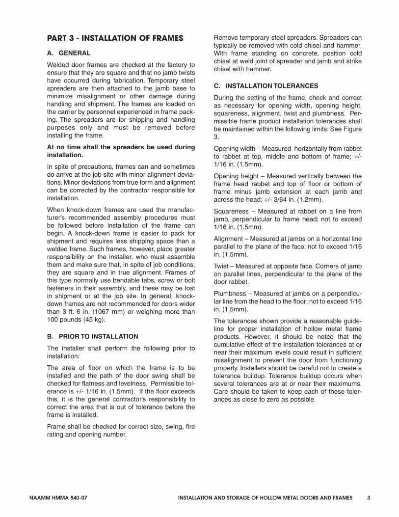
This manual was developed by representative members of the HollowMetal Manufacturers Association Division (HMMA) of the NationalAssociation of Architectural Metal Manufacturers (NAAMM) to provideinformation and guidance on the installation and storage of hollow metaldoors and frames. This manual contains advisory information only and ispublished as a public service by NAAMM and its HMMA Division.
NAAMM AND ITS HMMA DIVISION DISCLAIM ALL LIABILITY OF ANYKIND FOR THE USE, APPLICATION OR ADAPTATION OF MATERIALPUBLISHED IN THIS STANDARD.
Purchasers of NAAMM Standards may receive current information on allNAAMM Standards by calling or writing the National Association ofArchitectural Metal Manufacturers, or by visiting our website atwww.hollowmetal.org.
National Association of Architectural Metal Manufacturers800 Roosevelt RoadBldg. C, Suite 312
Glen Ellyn, Illinois 60137Phone: (630) 942-6591 Fax: (630) 790-3095
www.naamm.org
Copyright © 2007National Association of Architectural Metal Manufacturers
All Rights Reserved
20407_Cover.qxp 1/31/08 8:52 AM Page 2

NAAMM HMMA 840-07 INSTALLATION AND STORAGE OF HOLLOW METAL DOORS AND FRAMES i
TABLE OF CONTENTS
Part 1 – INTRODUCTIONA. Related Documents .................................................................................................................1
Part 2 - RECEIVING AND STORAGE OF MATERIAL ....................................................................
A. Receiving Material....................................................................................................................1
B. On Site Storage .........................................................................................................................1
Part 3 – INSTALLATION OF FRAMESA. General ......................................................................................................................................3
B. Prior to Installation.....................................................................................................................3
C. Installation Tolerances ..............................................................................................................3
D. Typical Installation Procedures................................................................................................5
E. Wall Constructions and Appropriate Anchors ......................................................................9
1. Masonry Walls ................................................................................................................10
2. Steel Stud Walls ..............................................................................................................11
3. Wood Stud Walls............................................................................................................13
4. Existing Masonry Walls...................................................................................................14
5. Completed Drywall.......................................................................................................15
F. Grouting of Frames .................................................................................................................16
G. Field Splicing............................................................................................................................16
Part 4 – HANGING OF DOORSA. General ....................................................................................................................................17
B. Operation Clearances ...........................................................................................................17
C. Care After Installation ............................................................................................................17
Part 5 - APPENDIXA. Grouting Hollow Metal Frames .............................................................................................A1
B. Defining Undercuts.................................................................................................................A2
C. Painting Hollow Metal Products............................................................................................A4
20407_Body 1/31/08 2:22 PM Page i

ii INSTALLATION AND STORAGE OF HOLLOW METAL DOORS AND FRAMES NAAMM HMMA 840-07
20407_Body 1/31/08 2:22 PM Page ii

NAAMM HMMA 840-07 INSTALLATION AND STORAGE OF HOLLOW METAL DOORS AND FRAMES 1
PART I - INTRODUCTION
This guide specification is intended to stress thenecessary precautions and requirements forreceipt, storage, handling and installation of hollowmetal products, and the skills essential in the hang-ing of doors.
The proper performance of most products dependsnot only on how they are manufactured, but howthey are installed. This is especially true of hollowmetal doors and frames. The installation of doorsand frames is an operation demanding care andskill, if the doors are to operate properly. Care inmanufacturing does not, in itself, guarantee satis-factory performance. Even the best designed andmost carefully constructed frames and doors, ifincorrectly installed, will not function properly.
Hollow metal work is fabricated in accordance withthe shop drawings, approved by the architect orengineer. Preparation for hardware or other itemssupplied by others is provided in accordance withthe information furnished to the hollow metal manu-facturer.
The hollow metal manufacturer is a material suppli-er, not a subcontractor. The manufacturer does notinclude the installation of their product in the build-ing, but only shipment in good condition from thefactory.
Should the General Contractor discover any error inthe hollow metal delivered to the job site, it is imper-ative that the hollow metal manufacturer be notifiedin writing and allowed sufficient time before initiatingany corrective measure in the field, so that the man-ufacturer can participate in solving the problem.Failure to do so could result in the cancellation ofthe warranty and/or fire label and non-acceptanceof any cost associated with repair.
Most member companies of the Hollow Metal Man-ufacturer’s Association Division of NAAMM havetheir own field representatives who are qualified notonly to do expert repair work but to determinewhether the fault lies with the manufacturer or withsome other party.
It is essential that material is properly stored prior toinstallation and skills are exercised in the setting offrames and hanging of doors.
RELATED DOCUMENTS
A. ANSI/A.250.11-2001 Recommended Erec-tion Instructions for Steel Frames
B. ANSI/NAAMM HMMA 801-05 Glossary ofTerms for Hollow Metal Doors and Frames
C. ANSI/NAAMM HMMA 841-07 Tolerancesand Clearances for Commercial HollowMetal Doors and Frames
D. NAAMM HMMA 820–87 Hollow MetalFrames
E. NFPA 80 Standard for Fire Doors and OtherOpening Protectives 2007 Edition
F. SDI-122-90 Installation & Troubleshootingfor Standard Steel Doors and Frames
PART 2 - RECEIVING AND STORAGEOF MATERIAL
A. RECEIVING
Upon delivery, the contractor responsible for receiv-ing hollow metal products shall thoroughly inspectfor damage. Cardboard and other wrappings shallbe removed for inspection and to promote air circu-lation. Any scratches or disfigurements caused inshipping or handling shall be promptly cleaned andtouched up with a direct to metal rust inhibitiveprimer.
Should damaged material be found, the GeneralContractor has the option of refusing delivery or toaccept the material as damaged. For coordinationpurposes, HMMA suggests that delivery should not
be refused, but rather accepted as damaged. Anydamaged items should be noted on the freight bill.Claims will not be honored by the freight carrier,unless the damaged items are noted on the freightbill at the time of delivery. The contractor shall noti-fy the hollow metal manufacturer in writing immedi-ately of any item signed for as damaged. The Gen-eral Contractor must telephone or write the localoffice of the freight carrier and request an inspec-tion of the damage. This procedure will help toexpedite the repair or replacement of the damageditems and the processing of the damage claim withthe freight carrier.
B. ON SITE STORAGE
Proper storage of hollow metal work at the con-struction site will help prevent damage to the primercoat of paint. Prime coated steel must be protectedwhen exposed to the elements such as high humid-
STORAGE AND INSTALLATION OF HOLLOW METAL DOORS AND FRAMES
20407_Body 1/31/08 2:22 PM Page 1

2 INSTALLATION AND STORAGE OF HOLLOW METAL DOORS AND FRAMES NAAMM HMMA 840-07
ity, salt air, rain, snow, and/or damp wrappingsetc.... Particular attention must, therefore, be givento steel products having a coat of factory appliedprimer. Primer is porous to properly receive andhold top coats. Water or moisture, in contact withprimer coated steel will seep through to the steel.An electrolytic action then follows, resulting in cor-rosion and causing the paint film to lose adhesion.The presence of oxygen at the water-air interfacebehind the loosened paint film accelerates corro-sive action and the prime coat further deteriorates.
Even when zinc coated steel is used to providecorrosion resistance, manufacturers of hollowmetal door and frame products have found thatone week of product exposure to water, due toimproper storage, can be equivalent to at least ayear of outdoor exposure to the elements.
NOTE: Paint manufacturers advise that the primertypically used by hollow metal manufacturersshould receive a finish coat of paint within 30 daysof delivery. It is the responsibility of the GeneralContractor to sand, touch up and clean prime paint-ed surfaces prior to finish painting in accordancewith the finish paint manufacturer’s instructions.
The following procedures shall always be observedin storing hollow metal doors and frames at the jobsite:
1. Store all materials in a dry area, under cover. Allproducts shall be stored where they will not beexposed to, or come in contact with the ele-ments.
2. Do not use non-vented plastic or canvas. Thesematerials create a humidity chamber, whichpromotes blistering and corrosion.
3. Store doors and frames in an upright positionwith heads uppermost, Figures 1 and 2.
4. Place no more than 5 doors or welded framesin a group. Small groups not only minimize thelikelihood of damage due to excess handling,but also facilitate selection from the group forinstallation. In the case of multi-opening frames,no more than three units should be stored in agroup, to avoid serious damage to the bottommost frame.
5. Place all material on planking or blocking atleast 4 in. (100 mm) off the ground, 2 in. (50mm) off a paved area or the floor slab.
6. Provide at least 1/4 in. (6.4 mm) space betweenall units to permit air circulation.
FIGURE 1 FRAME STORAGE
FIGURE 2 DOOR STORAGE
WOODPLANKING
WOODPLANKING
WOODPLANKING
WOODPLANKING
20407_Body 1/31/08 2:23 PM Page 2
NAAMM HMMA 840-07 INSTALLATION AND STORAGE OF HOLLOW METAL DOORS AND FRAMES 3
PART 3 - INSTALLATION OF FRAMES
A. GENERAL
Welded door frames are checked at the factory toensure that they are square and that no jamb twistshave occurred during fabrication. Temporary steelspreaders are then attached to the jamb base tominimize misalignment or other damage duringhandling and shipment. The frames are loaded onthe carrier by personnel experienced in frame pack-ing. The spreaders are for shipping and handlingpurposes only and must be removed beforeinstalling the frame.
At no time shall the spreaders be used duringinstallation.
In spite of precautions, frames can and sometimesdo arrive at the job site with minor alignment devia-tions. Minor deviations from true form and alignmentcan be corrected by the contractor responsible forinstallation.
When knock-down frames are used the manufac-turer’s recommended assembly procedures mustbe followed before installation of the frame canbegin. A knock-down frame is easier to pack forshipment and requires less shipping space than awelded frame. Such frames, however, place greaterresponsibility on the installer, who must assemblethem and make sure that, in spite of job conditions,they are square and in true alignment. Frames ofthis type normally use bendable tabs, screw or boltfasteners in their assembly, and these may be lostin shipment or at the job site. In general, knock-down frames are not recommended for doors widerthan 3 ft. 6 in. (1067 mm) or weighing more than100 pounds (45 kg).
B. PRIOR TO INSTALLATION
The installer shall perform the following prior toinstallation:
The area of floor on which the frame is to beinstalled and the path of the door swing shall bechecked for flatness and levelness. Permissible tol-erance is +/- 1/16 in. (1.5mm). If the floor exceedsthis, it is the general contractor’s responsibility tocorrect the area that is out of tolerance before theframe is installed.
Frame shall be checked for correct size, swing, firerating and opening number.
Remove temporary steel spreaders. Spreaders cantypically be removed with cold chisel and hammer.With frame standing on concrete, position coldchisel at weld joint of spreader and jamb and strikechisel with hammer.
C. INSTALLATION TOLERANCES
During the setting of the frame, check and correctas necessary for opening width, opening height,squareness, alignment, twist and plumbness. Per-missible frame product installation tolerances shallbe maintained within the following limits: See Figure3.
Opening width – Measured horizontally from rabbetto rabbet at top, middle and bottom of frame; +/-1/16 in. (1.5mm).
Opening height – Measured vertically between theframe head rabbet and top of floor or bottom offrame minus jamb extension at each jamb andacross the head; +/- 3/64 in. (1.2mm).
Squareness – Measured at rabbet on a line fromjamb, perpendicular to frame head; not to exceed1/16 in. (1.5mm).
Alignment – Measured at jambs on a horizontal lineparallel to the plane of the face; not to exceed 1/16in. (1.5mm).
Twist – Measured at opposite face. Corners of jambon parallel lines, perpendicular to the plane of thedoor rabbet.
Plumbness – Measured at jambs on a perpendicu-lar line from the head to the floor; not to exceed 1/16in. (1.5mm).
The tolerances shown provide a reasonable guide-line for proper installation of hollow metal frameproducts. However, it should be noted that thecumulative effect of the installation tolerances at ornear their maximum levels could result in sufficientmisalignment to prevent the door from functioningproperly. Installers should be careful not to create atolerance buildup. Tolerance buildup occurs whenseveral tolerances are at or near their maximums.Care should be taken to keep each of these toler-ances as close to zero as possible.
20407_Body 1/31/08 2:25 PM Page 3

4 INSTALLATION AND STORAGE OF HOLLOW METAL DOORS AND FRAMES NAAMM HMMA 840-07
FIGURE 3FRAME INSTALLATION TOLERANCES
90º
SQUARENESS; MEASURED AT RABBET ON A LINE FROM JAMB PERPENDICULAR TO FRAME HEAD.
PLUMBNESS; MEASURED AT JAMBS ON A PERPENDICULAR LINE FROM THE HEAD TO THE FLOOR.
ALIGNMENT; MEASURED AT JAMBS ON A HORIZONTAL LINE PARALLEL TO THE PLANE OF THE FACE.
TWIST; MEASURED AT OPPOSITE FACECORNERS OF JAMBS ON PARALLELLINES, PERPENDICULAR TO THE PLANE OF THE DOOR RABBET.
PROFILE MAY VARYAS A FUNCTIONAL DESIGN
HINGE ORSTRIKE JAMB
HEAD
90º
1"16
161"
1"1616
1"
161"
1"16
1"16
1"16
OPENING WIDTH; MEASURED HORZON-TALLY FROM RABBET TO RABBET AT TOP, MIDDLE AND BOTTOM OF FRAME; +/- 1/16 IN. (1.5mm)
OPENING HEIGHT; MEASURED VERTICALLY BETWEEN FRAME HEAD RABBET AND TOP OF FLOOR OR BOTTOM OF FRAME MINUS JAMB EXTENSIONS AT EACH JAMB AND ACROSS THE HEAD; +/- 3/64 IN. (1.2mm)
20407_Body 1/31/08 2:25 PM Page 4

NAAMM HMMA 840-07 INSTALLATION AND STORAGE OF HOLLOW METAL DOORS AND FRAMES 5
D. TYPICAL INSTALLATION PROCEDURES
Position frame in the correct location. Brace theframe as shown, Figure 4. Do not brace in the direc-tion of intended wall.
FIGURE 4FRAME BRACING
With frame in position, install the temporary woodspreaders. The wood spreader, Figure 5, must be
square and no less than 1 in. (25 mm) thick. Correctlength is the door opening width between the jambsat the header. Cut clearance notches for framestops. Spreader must be nearly as wide as framedepth for proper installation. Install a spreader atthe bottom of the frame and a second wood spread-er at the mid or strike point to maintain a properdoor opening and to prevent bowing of the jambs,Figure 6. Clamp or wire spreaders to frame to holdspreaders in place until the frames are set perma-nently in the wall.
FIGURE 5WOOD SPREADER
FIGURE 6SPREADER LOCATION
2"x4" BRACE
SUPPORT BRACEAT FLOOR
DOOR OPENING AT HEADER
FRA
ME
DEP
TH
SPREADER
SPREADERS
20407_Body 1/31/08 2:26 PM Page 5

6 INSTALLATION AND STORAGE OF HOLLOW METAL DOORS AND FRAMES NAAMM HMMA 840-07
At frames with jamb opening heights greater than 8ft. (2438mm) or frame face dimensions less than 1-1/2 in. (38mm), install an additional wood spreader.Space wood spreaders at a maximum of 36 in.(914mm) intervals between header and bottom offrame, Figure 7.
FIGURE 7SPREADER LOCATION AT
LARGE JAMB OPENING HEIGHTS
At frames with sidelights where the sidelight sillintersects the door jamb near the strike, it is imper-ative that a wood spreader is located at this loca-tion, Figure 8.
FIGURE 8SPREADER LOCATION AT SIDELIGHTS
SPREADERS
SPREADERS
20407_Body 1/31/08 2:26 PM Page 6

NAAMM HMMA 840-07 INSTALLATION AND STORAGE OF HOLLOW METAL DOORS AND FRAMES 7
The installation contractor shall have a carpenterlevel and builder’s square. Level the head by posi-tioning the level to the head door rabbet, Figure 9. Ifnecessary, adjust for high spots in floor by shim-ming under the jamb floor anchor, Figure 13a.Equalize them through an adjustable floor anchor, ifspecified, Figure 13b. Note, for labeled openingsthe maximum floor clearance is 3/4 in. (19mm).
FIGURE 9LEVELING THE HEAD
With builder’s square, check frame for squareness.Position square against jamb and head at door rab-bet, adjust as required, Figure 10.
FIGURE 10SQUARENESS
With carpenter level check the frame for plumbnessand alignment: For plumbness, position levelagainst both hinge and strike jambs in the rabbet.For alignment; Position level against both hinge andstrike jambs on the stop, adjust as required, Figure 11.
FIGURE 11PLUMBING AND ALIGNMENT
With builder’s square, check jambs for twist. Posi-tion square against door rabbet and project line per-pendicular to the plane of the door rabbet, adjust asrequired, Figure 12.
FIGURE 12FRAME TWIST CHECK
SCETION A-A
ALI
GN
MEN
T
LEVEL
PLUMBA
LEVEL
A
LEVEL
LEVEL
20407_Body 1/31/08 2:26 PM Page 7
8 INSTALLATION AND STORAGE OF HOLLOW METAL DOORS AND FRAMES NAAMM HMMA 840-07
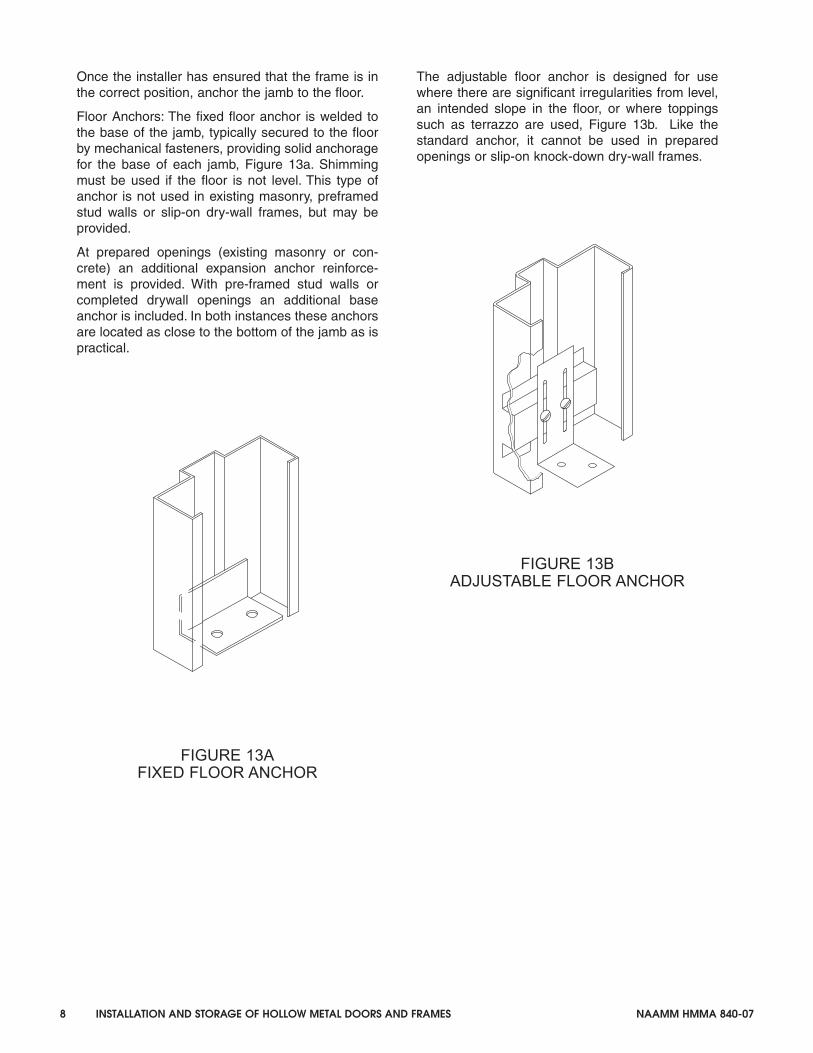
Once the installer has ensured that the frame is inthe correct position, anchor the jamb to the floor.
Floor Anchors: The fixed floor anchor is welded tothe base of the jamb, typically secured to the floorby mechanical fasteners, providing solid anchoragefor the base of each jamb, Figure 13a. Shimmingmust be used if the floor is not level. This type ofanchor is not used in existing masonry, preframedstud walls or slip-on dry-wall frames, but may beprovided.
At prepared openings (existing masonry or con-crete) an additional expansion anchor reinforce-ment is provided. With pre-framed stud walls orcompleted drywall openings an additional baseanchor is included. In both instances these anchorsare located as close to the bottom of the jamb as ispractical.
FIGURE 13AFIXED FLOOR ANCHOR
The adjustable floor anchor is designed for usewhere there are significant irregularities from level,an intended slope in the floor, or where toppingssuch as terrazzo are used, Figure 13b. Like thestandard anchor, it cannot be used in preparedopenings or slip-on knock-down dry-wall frames.
FIGURE 13BADJUSTABLE FLOOR ANCHOR
20407_Body 1/31/08 2:27 PM Page 8

NAAMM HMMA 840-07 INSTALLATION AND STORAGE OF HOLLOW METAL DOORS AND FRAMES 9
E. WALL CONSTRUCTIONS ANDAPPROPRIATE ANCHORS
Proper frame anchoring is vitally important to theproper performance of the door opening. A varietyof jamb wall anchors are available to suit the vari-ous types of wall construction. Anchors shown onthe following pages are but a few of the variety ofanchoring methods available. For additional details,refer to HMMA 820 Hollow Metal Frames.
ANCHOR SPACING
Anchor Spacing: HMMA specifications require thatthe number of wall anchors used on each jamb, inall cases, be as follows:
A. Openings in Masonry Walls. Frames withexpansion bolt anchors; Anchors spaced amaximum of 6 in. (152 mm) from the top andbottom, with intermediate spacing at a maxi-mum of 26 in. (660 mm) o/c. See Table 1.
B. Openings in stud partitions with steel or woodstud anchors: Near hinges and directly oppositeon strike jamb. See Table 1.
C. Anchor quantity for slip-on drywall frames shallbe as per manufacturer’s standards and labelrequirements.
D. Wall anchors locations and quantity are in addi-tion to floor anchors, when required.
Table 1
Frame Anchor Spacing
Frame Height Masonry Walls Stud Partitions
> 0 in. < 60 in. (1524 mm) 2 3
> 60 in. < 90 in. (2286 mm) 3 4
> 90 in. < 96 in. (2438 mm) 4 5
> 96 in. 4 + 1 per 24 in. 5 + 1 per 24 in.
(610 mm)
20407_Body 1/31/08 2:27 PM Page 9
10 INSTALLATION AND STORAGE OF HOLLOW METAL DOORS AND FRAMES NAAMM HMMA 840-07
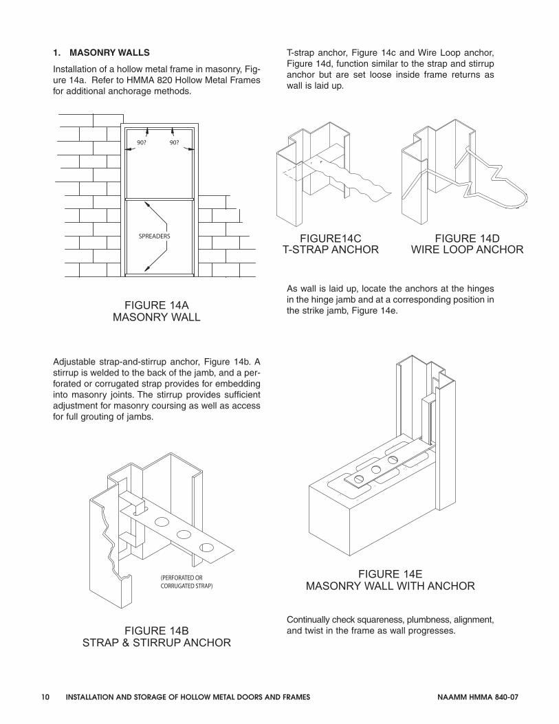
1. MASONRY WALLS
Installation of a hollow metal frame in masonry, Fig-ure 14a. Refer to HMMA 820 Hollow Metal Framesfor additional anchorage methods.
FIGURE 14AMASONRY WALL
Adjustable strap-and-stirrup anchor, Figure 14b. Astirrup is welded to the back of the jamb, and a per-forated or corrugated strap provides for embeddinginto masonry joints. The stirrup provides sufficientadjustment for masonry coursing as well as accessfor full grouting of jambs.
FIGURE 14BSTRAP & STIRRUP ANCHOR
T-strap anchor, Figure 14c and Wire Loop anchor,Figure 14d, function similar to the strap and stirrupanchor but are set loose inside frame returns aswall is laid up.
As wall is laid up, locate the anchors at the hingesin the hinge jamb and at a corresponding position inthe strike jamb, Figure 14e.
FIGURE 14EMASONRY WALL WITH ANCHOR
Continually check squareness, plumbness, alignment,and twist in the frame as wall progresses.
SPREADERS
90? 90?
CORRUGATED STRAP)(PERFORATED OR
FIGURE14CT-STRAP ANCHOR
FIGURE 14DWIRE LOOP ANCHOR
20407_Body 1/31/08 2:27 PM Page 10

NAAMM HMMA 840-07 INSTALLATION AND STORAGE OF HOLLOW METAL DOORS AND FRAMES 11
2. STEEL STUD WALLS
Installation of a hollow metal frame in steel studwall, Figure 15a. Refer to HMMA 820 Hollow MetalFrames for additional anchorage methods.
FIGURE 15ASTEEL STUD WALL
FIGURE 15BZEE SHAPED STEEL STUD ANCHOR
Zee shaped anchor, Figure 15b, is welded to bothrabbets inside the jamb. Steel studs are mechani-cally fastened to the exposed flange through thethroat of the stud.
FIGURE 15CCOMBINATION WOOD/STEEL
STUD ANCHOR
Combination wood/steel stud anchor, Figure 15c,are welded or friction fit inside the jamb. Additionalhorizontal straps allows fastening to the face of thestud in lieu of through the throat. Typically usedwhen the steel stud wall is assembled prior to set-ting the frame.
When fastening through the face of the stud, it isextremely important that the head height of fasten-ers are considered to ensure that the combinedthickness of wall stud, fastener head height and fin-
ished wall material does not exceed the designedwall thickness. The effects of increased wall thick-ness will result in the frame faces being forced outduring drywall installation, bowing the jamb profile.The corner between header and jamb will be visu-ally bellied, and possible misalignment of framemay occur.
Due to this issue and with irregularities in wall con-struction width, it is strongly recommended thatframes overlapping the wall, (except slip-on con-struction), have a throat dimension 1/8 in. (3.1mm)greater than dimensioned wall thickness.
SPREADERS
90?
JAMB
STUDS
CEILING RUNNER
HEADER STUD
FLOOD RUNNER
90?
20407_Body 1/31/08 2:28 PM Page 11

12 INSTALLATION AND STORAGE OF HOLLOW METAL DOORS AND FRAMES NAAMM HMMA 840-07
Position the vertical steel studs in the frame throatopening in accordance with architect’s details.Attach the vertical steel studs to floor and ceilingrunners and fasten to the steel stud anchors withmechanical fasteners, Figure 15d.
FIGURE 15DSTEEL STUD WALL WITH ANCHOR
Wall Construction: It is extremely important that thesteel stud manufacturer’s recommendation on thick-ness and general construction technique be fol-lowed to ensure that a solid and stable opening isachieved.
Figure 16a-d represents four methods of steel studheader connections to cripple studs above frameopenings. Extreme precaution must be taken toensure that any fasteners applied through face ofstuds or any construction will not increase the wall
thickness.
Continually check squareness, plumbness, align-ment, and twist in the frame as wall progresses.
FIGURE 16ARECOMMENDED
FIGURE 16BACCEPTABLE
FIGURE 16CNOT RECOMMENDED
FIGURE 16DNOT RECOMMENDED
FOLDED
HEADER
SCREWSCENTERCRIPPLE STUD
UPWARD
HEADER
SCREWS
OPTIONALCRIPPLE STUD
HEADER
FOLD DOWNSCREWS
SCREWS
SCREWHEADER
20407_Body 1/31/08 2:28 PM Page 12

NAAMM HMMA 840-07 INSTALLATION AND STORAGE OF HOLLOW METAL DOORS AND FRAMES 13
3. WOOD STUD WALLS
Installation of a hollow metal frame in a wood studwall, Figure 17a. Refer to HMMA 820 Hollow MetalFrames for additional anchorage methods.
FIGURE 17AWOOD STUD WALL
Wood stud walls can be constructed after the frameis set or prior to setting the frame. For constructingwall after the frame is set, follow guidelines same assteel stud walls. For constructing wall prior to settingthe frame, follow these guidelines;
Rough Stud Opening:
A. The width of the opening shall be the overallframe width plus 1/2 in. (12.7 mm).
B. The height of the opening shall be the overallframe height plus 1/4 in. (6.4 mm).
Place the frame in the rough stud opening. Bend the
anchor tabs around the stud, leaving the desiredclearance between the frame return and stud, forinserting the finished wall material. Set the spread-ers and level, plumb and align the frame. Check fortwist in jamb. Shim by other and/or adjust as nec-essary
Square the frame at the top corner and nail the topanchor to the stud on ONE JAMB ONLY. Recheckthe level, plumb and alignment of the frame at theother corner and continue to nail the balance of theanchors to the studs. Repeat the same process forthe opposite jamb.
It is extremely important that the head of the fas-teners are considered to ensure that the combinedthickness of wall stud, fastener head height and fin-ished wall material does not exceed the designedwall thickness.
Wood stud anchors, Figure 17b and 17c are weld-ed to the back of the jambs. Figure 17d is eitherwelded to back of the jamb or friction fit and avail-able for wood or steel stud walls.
FIGURE 17B FIGURE 17CWOOD-STUD ANCHORS
FIGURE 17DCOMBINATION WOOD/STEEL
STUD ANCHOR
FIGURE 17EWOOD STUD WALL WITH ANCHORS
90? 90?
NOTE:DOUBLE STUD
SPREADERS
20407_Body 1/31/08 2:28 PM Page 13
14 INSTALLATION AND STORAGE OF HOLLOW METAL DOORS AND FRAMES NAAMM HMMA 840-07
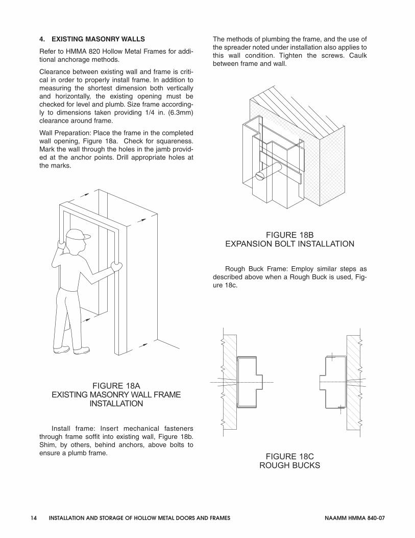
4. EXISTING MASONRY WALLS
Refer to HMMA 820 Hollow Metal Frames for addi-tional anchorage methods.
Clearance between existing wall and frame is criti-cal in order to properly install frame. In addition tomeasuring the shortest dimension both verticallyand horizontally, the existing opening must bechecked for level and plumb. Size frame according-ly to dimensions taken providing 1/4 in. (6.3mm)clearance around frame.
Wall Preparation: Place the frame in the completedwall opening, Figure 18a. Check for squareness.Mark the wall through the holes in the jamb provid-ed at the anchor points. Drill appropriate holes atthe marks.
FIGURE 18AEXISTING MASONRY WALL FRAME
INSTALLATION
Install frame: Insert mechanical fastenersthrough frame soffit into existing wall, Figure 18b.Shim, by others, behind anchors, above bolts toensure a plumb frame.
The methods of plumbing the frame, and the use ofthe spreader noted under installation also applies tothis wall condition. Tighten the screws. Caulkbetween frame and wall.
FIGURE 18BEXPANSION BOLT INSTALLATION
Rough Buck Frame: Employ similar steps asdescribed above when a Rough Buck is used, Fig-ure 18c.
FIGURE 18CROUGH BUCKS
20407_Body 2/6/08 11:10 AM Page 14

NAAMM HMMA 840-07 INSTALLATION AND STORAGE OF HOLLOW METAL DOORS AND FRAMES 15
5. COMPLETED DRYWALL
Wall Construction: It is very important that the studmanufacturer’s recommendation on thickness andgeneral construction technique be followed toensure that a solid and stable opening is achieved.For example, double studding at the opening is nec-essary; the header stud must be the same width asthe jamb stud. It is particularly important that theoverlapping of vertical and horizontal steel studs beavoided since this produces oversize walls.This could create significant installation problemswhen slip-on drywall frames are used.
Rough Stud Openings: A variety of anchoring tech-niques preclude the establishment of a definiterough opening standard. Follow the frame manufac-turers recommendations.
FIGURE 19AINSTALLATION SEQUENCE
Installation Sequence: Installation varies from man-ufacturer to manufacturer. Consult the supplyingmanufacturer’s literature for exact instructions. Atypical installation cycle may be as follows, Figure19a.
1. Slide the header in place over the wall approxi-mately in the center of the opening.
2. Install one jamb by sliding it over the wall at thetop. Push the bottom of the member until it isapproximately vertical.
3. Install the other jamb in a similar manner. Theframe should be installed with all excessiverough opening clearances thrown to the hingeside. The weight of the door will tend to causemovement, within the opening, toward the strikejamb.
4. Join the horizontal header to the jambs., Figure19b . This is normally done by inserting tabsinto the slots, or screws into the holes or a com-bination of both.
FIGURE 19BCORNER CONNECTIONKNOCKDOWN SLIP-ON
Plumb and square the opening and check thejambs for twist. Some installers prefer to hang thedoor at this point, permitting the door to aid in per-forming this function.
SEE F19b
TABS
SLOTS
SLOTS
SCREW
20407_Body 1/31/08 2:29 PM Page 15
16 INSTALLATION AND STORAGE OF HOLLOW METAL DOORS AND FRAMES NAAMM HMMA 840-07
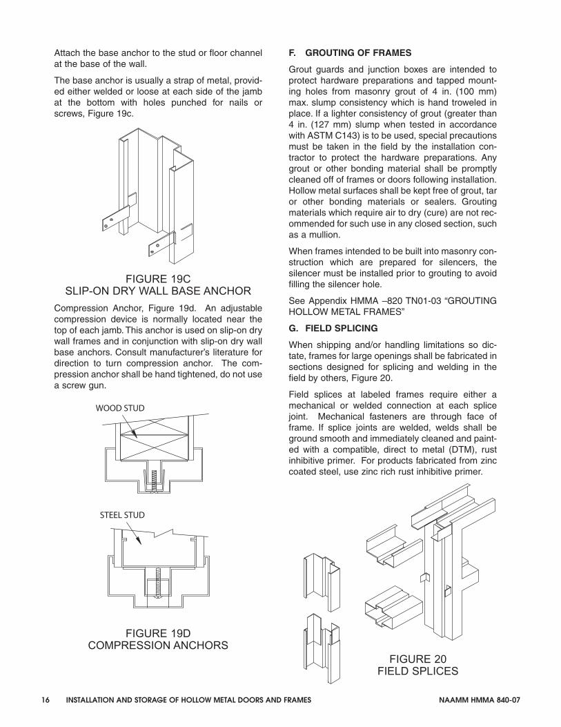
Attach the base anchor to the stud or floor channelat the base of the wall.
The base anchor is usually a strap of metal, provid-ed either welded or loose at each side of the jambat the bottom with holes punched for nails orscrews, Figure 19c.
FIGURE 19CSLIP-ON DRY WALL BASE ANCHOR
Compression Anchor, Figure 19d. An adjustablecompression device is normally located near thetop of each jamb. This anchor is used on slip-on drywall frames and in conjunction with slip-on dry wallbase anchors. Consult manufacturer’s literature fordirection to turn compression anchor. The com-pression anchor shall be hand tightened, do not usea screw gun.
FIGURE 19DCOMPRESSION ANCHORS
F. GROUTING OF FRAMES
Grout guards and junction boxes are intended toprotect hardware preparations and tapped mount-ing holes from masonry grout of 4 in. (100 mm)max. slump consistency which is hand troweled inplace. If a lighter consistency of grout (greater than4 in. (127 mm) slump when tested in accordancewith ASTM C143) is to be used, special precautionsmust be taken in the field by the installation con-tractor to protect the hardware preparations. Anygrout or other bonding material shall be promptlycleaned off of frames or doors following installation.Hollow metal surfaces shall be kept free of grout, taror other bonding materials or sealers. Groutingmaterials which require air to dry (cure) are not rec-ommended for such use in any closed section, suchas a mullion.
When frames intended to be built into masonry con-struction which are prepared for silencers, thesilencer must be installed prior to grouting to avoidfilling the silencer hole.
See Appendix HMMA –820 TN01-03 “GROUTINGHOLLOW METAL FRAMES”
G. FIELD SPLICING
When shipping and/or handling limitations so dic-tate, frames for large openings shall be fabricated insections designed for splicing and welding in thefield by others, Figure 20.
Field splices at labeled frames require either amechanical or welded connection at each splicejoint. Mechanical fasteners are through face offrame. If splice joints are welded, welds shall beground smooth and immediately cleaned and paint-ed with a compatible, direct to metal (DTM), rustinhibitive primer. For products fabricated from zinccoated steel, use zinc rich rust inhibitive primer.
FIGURE 20FIELD SPLICES
WOOD STUD
STEEL STUD
20407_Body 1/31/08 2:29 PM Page 16
NAAMM HMMA 840-07 INSTALLATION AND STORAGE OF HOLLOW METAL DOORS AND FRAMES 17
PART 4 - HANGING OF DOORS
A. GENERAL
It is the responsibility of the installer to hang alldoors and install all hardware prior to finish paint-ing. Doors shall be reinforced, drilled and tapped atthe factory for templated mortise hardware only, inaccordance with the approved hardware scheduleand templates provided by the hardware supplier.Where surface mounted hardware, anchor hinges,thrust pivot, pivot reinforced hinges, or non-templat-ed hardware apply, doors shall be reinforced, withdrilling and tapping done in the field by others.
Experienced craftsmanship and care are essentialin the hanging of metal doors. The use of steelhinge shims may be required to provide uniformclearance around the door and alleviate “hingebind”. Figure 21 and Figure 22.
The door-to-frame clearance adjustment toward thestrike jamb (in the direction of arrow S) in Figure 21.can be accomplished by placing a metal shim orshims under the hinge leaf or leaves along the bar-rel edge of the hinge. Adjusting toward the hingejamb (in the direction of arrow H) in Figure 22 canbe done by placing a metal shim or shims under theouter edge of the hinge leaf or leaves.
B. OPERATION CLEARANCES
Edge clearances for swinging hollow metal doorsand as specified in NFPA 80, shall be provided forthe functional operation of the assembly and shallnot exceed the following (for all door heights)
Between door and frame at head and jamb. 1/8 in.(3.1 mm) +/- 1/16 in. (1.5 mm)
Between edges of pairs of doors. 1/8 in. (3.1 mm)+/- 1/16 in. (1.5 mm)
Floor clearance for fire rated swinging hollow metaldoors shall not exceed 3 /4 in. (19mm). Floor clear-ance shall be provided for the functional operationof all swinging hollow metal doors and shall not beless than 1/8 in. (3.1mm)
The Architect must define the distance from the topof the floor / finished floor to top of floor covering soappropriate undercuts can be provided. Floor / Fin-ish Floor is defined as the top of the concrete orstructural slab. HMMA uses the term “top of floorcovering “ to describe the NFPA term “nominal sur-face of floor covering”. Please refer to HMMA-810TN01-03 Tech Note, “Defining Undercuts.”
C. CARE AFTER INSTALLATION
Doors installed prior to completion of constructionmay be subject to damage from other tradesbecause of improper protection or carelessness onthe part of construction workers.
Prime or painted surfaces which have beenscratched or otherwise marred during installation(including field welding) and/or cleaning, shallpromptly be finished smooth, cleaned, treated formaximum paint adhesion, and touched up with adirect to metal (DTM), rust inhibitive primer.
Acid washing of masonry construction adjacent todoor and frame installations will damage the steelsurfaces whether primed or finish painted.
If not cleaned immediately, rusting will occur. Forthis reason steel doors and frames must be pro-tected. If exposed to an acid wash, all primed orpainted steel surfaces must be throughly cleanedwith particular attention being given to hidden areassuch as those areas under glazing stops.
For additional information regarding the painting ofhollow metal products, please refer to HMMA-840TN01-07 Tech Note, “Painting Hollow Metal Prod-ucts”
20407_Body 1/31/08 2:29 PM Page 17

FIGURE 21SHIMMING TO INCREASE
CLEARANCE AT HINGE EDGE
Using shim A only, door will be relocated in directionof arrow S.
Using shim B only, both door and centerline ofhinge barrel will move in direction of arrow S.
Using both shims A and B will move the door furtherin direction of arrow S than by using either A or Balone, and hinge barrel will be relocated just asusing B alone.
FIGURE 22SHIMMING TO DECREASE
CLEARANCE AT HINGE EDGE
Using shim C only, door will be relocated in direc-tion of arrow H.
Using shim D only, Both door and centerline ofhinge barrel will move in direction of arrow H.
Using both shims C and D will move the door fur-ther in direction of arrow H than by using either C orD alone, and hinge barrel will be relocated just asby using D alone.
18 INSTALLATION AND STORAGE OF HOLLOW METAL DOORS AND FRAMES NAAMM HMMA 840-07
HINGE JAMB
SHIM B
SHIM A
S
HINGEREINFORCEMENT
HINGEREINFORCEMENT
USE HINGE SHIMS TO ADJUST DOOR CLEARANCE
H
SHIM D
SHIM C
20407_Body 1/31/08 2:29 PM Page 18

NAAMM HMMA 840-07 INSTALLATION AND STORAGE OF HOLLOW METAL DOORS AND FRAMES A1
National Association ofArchitectural Metal ManufacturersTechNotesotesTechNotes
HMMA-820 TN02-03
Grouting Hollow Metal Frames
Grout, when used in accordance with industry guidelines, can improve frame durability, sound deadening,and, depending on wall construction, increase frame anchorage strength. Grouting of the frame does notincrease door durability, nor is it required for fire-rated frames. For most commercial applications, groutingof mullions and other closed sections is not recommended.
For applications covered by ANSI/NAAMM HMMA 862, “Guide Specifications for Commercial SecurityHollow Metal Doors and Frames,” and ANSI/NAAMM HMMA 863, “Guide Specifications for DetentionSecurity Hollow Metal Doors and Frames,” the standards require that “frame jambs shall be fully groutedto provide added security protection against battering, wedging, spreading, and other means of forcingopen the door”.
Grout is a water-based product. If not used properly, it can destroy the opening in a very short time.Grout can be either “mortar”, which is a masonry mixture of lime, cement, sand, and water, or “plaster”,which is a gypsum-based product.
Plaster grout dries by exposure to air. When a frame member is filled solid with plaster grout, only thoseareas exposed to air will dry and harden, while the center remains wet (uncured). The water remaining inthe plaster grout can rust the frame from the inside. Plaster grout should not be used.
Mortar grout cures by chemical reaction and hardens throughout. Use mortar grout.
Frames are not designed to act as forms for grout. Grout must have a maximum 4 in. slump and behand troweled in place. Bracing of the frame may be necessary prior to grouting to prevent sagging ofthe header or bowing of the jamb due to weight or pressure of the grout. Grout should not be installedafter gypsum wallboard is installed, as the liquid within the grout will deteriorate the wallboard.
When dictated by temperatures, anti-freezing agents for mortar may be recommended by specifications.These agents can adversely affect metal, and all surfaces in contact with the grout must be coated with acorrosion resistant material.
It is recommended that the contractor be responsible for the grouting and for any required barrier coating.It is also his responsibility to use care in the application of the grout.
HMMA-820 TN01-03
APPENDIX 1(Not part of the Standard)
20407_Body 1/31/08 2:30 PM Page 19

A2 INSTALLATION AND STORAGE OF HOLLOW METAL DOORS AND FRAMES NAAMM HMMA 840-07
National Association ofArchitectural Metal ManufacturersTechNotesotesTechNotes
HMMA-810 TN01-03
Defining UndercutsReview of established definitions.
1. “ACTUAL DOOR HEIGHT” – The door open-ing height minus top clearance and undercut.
2. “DOOR OPENING HEIGHT” – The distancemeasured vertically between the frame headrabbet and top of floor or bottom of frameminus jamb extension.
3. “FINISHED FLOOR” – See “Floor”
4. “FLOOR” – The top of the concrete or struc-tural slab.
5. “FLOOR CLEARANCE” – The distancebetween the bottom of the door and the top ofthe material directly below the door. This varieswith application, such as concrete, any floorcovering and/or a threshold.
6. “FLOOR COVERING” – Any material appliedon top of the floor that extends under the doorin its closed position or under the door as itswings to its fully open position.
7. “UNDERCUT” – The distance between thebottom of door and the bottom of frame. Theformula in which to determine Undercut isderived by adding the total sum of the follow-ing (Floor Clearance + Floor Covering Thick-ness + Threshold Height (assuming the thresh-old is mounted on top of the floor covering) +Jamb Extensions Height.
8. “JAMB EXTENSIONS” – That portion of ajamb or mullion which extends below the levelof the floor.
Typically frames are intended to be installeddirectly on the floor. When no floor coverings orthresholds are used, the dimension for “Undercut”is the same as for “Floor Clearance.” See Figure #1.
Floor coverings, such as carpet, resilient orceramic tile, are typically installed on top of thefloor, fitted around the frame, and under the door.In this situation, the formula for figuring Undercutis the total of the Floor Clearance + Floor Cover-ing Thickness. See Figure #2.
When a threshold is used, it is installed on top ofthe floor or floor covering, fitted around the frameand under the door. Again the formula for figuring“Undercut” changes. Undercut is the total of the
AC
TU
AL
DO
OR
HE
IGH
T
BOTTOM
OF FRAME
DO
OR
OP
EN
ING
HE
IGH
T
Figure #1
CLEARANCE
FLOOR
UNDERCUT,
FLOOR CLEARANCE
FLOOR
FLOOR CLEARANCE
Figure #2
AC
TU
AL
DO
OR
HE
IGH
T
FLOOR
DO
OR
OP
EN
ING
HE
IGH
T
BOTTOM
OF FRAME
UNDERCUT
FLOOR
COVERING
APPENDIX 2(Not part of the Standard)
20407_Body 1/31/08 2:30 PM Page 20

NAAMM HMMA 840-07 INSTALLATION AND STORAGE OF HOLLOW METAL DOORS AND FRAMES A3
Floor Clearance + Threshold Height + Floor Cov-ering Thickness. See Figure #3.
In situations with specialized floors such as thickceramic tile or terrazzo, the frame is typicallyinstalled prior to the installation of the floor.
One method is to install the frame with adjustablefloor anchors or for the frame to be installed on ablock or shim. This allows the frame to be posi-tioned, as required, to accommodate the floorheight. See Figures #4A and #4B. Both illustrate araised frame condition in which the bottom offrame is positioned to be directly on top of thefloor after the floor is installed. In this situation, thedimension measured for Undercut is also thesame as Floor Clearance.
Another method, called “below floor installation,” is to install the frame directly on the rough slab.After the frame is installed, the floor is theninstalled around the frame. That portion of the
frame that is covered by the floor is called jambextensions. The formula for figuring “Undercut” isthe total of the Floor Clearance + Jamb Exten-sions. See Figure #5A and #5B.
The Architect/Designer must be very specificwithin specifications and contract drawings,which should include detailed drawings illustratingconditions for each floor, including thicknessesand materials. These drawings should designatethe height at which the hollow metal frame shouldbe set. Thresholds and hardware items requiringspecific floor clearances shall be listed in thehardware schedule, which allows the door andframe manufacturer to properly size each opening.
Within the door and frame industry, both the Hol-low Metal Manufacturers Association (HMMA) adivision of the National Association of Architectur-al Metal Manufacturers (NAAMM) and the SteelDoor Institute (SDI), publish recommended clear-ances. In addition, the National Fire ProtectionAssociation (NFPA) Publication 80, “Standard forFire Doors and Fire Windows,” regulates theinstallation and maintenance of labeled openings,and lists several different scenarios consisting ofdifferent floor material and the maximum clear-ance under the bottoms of doors.
FLOOR
COVERING
Figure #3
THRESHOLD
AC
TU
AL
DO
OR
HE
IGH
T
DO
OR
OP
EN
ING
HE
IGH
T
FLOOR CLEARANCE
UNDERCUT
BOTTOM
OF FRAME
FLOOR
AC
TU
AL
DO
OR
HE
IGH
T
FLOOR CLEARANCE
FLOOR
Figure #5A
UN
DE
RC
UT
DO
OR
OP
EN
ING
HE
IGH
T
BOTTOM
OF FRAME
JAMB
EXTENSION
DO
OR
OP
EN
ING
HE
IGH
T
AC
TU
AL
DO
OR
HE
IGH
T
FLOOR CLEARANCE
BOTTOM
OF FRAME
Figure #5B
EXTENSION
JAMB
UN
DE
RC
UT
FLOOR
Figure #4B
BOTTOM
OF FRAME
DO
OR
OP
EN
ING
HE
IGH
T
AC
TU
AL
DO
OR
HE
IGH
T
FLOOR CLEARANCE,
UNDERCUT
FLOOR
BLOCKING
BOTTOM
OF FRAME
FLOOR
DO
OR
OP
EN
ING
HE
IGH
T
Figure #4A
AC
TU
AL
DO
OR
HE
IGH
T
FLOOR CLEARANCE,
UNDERCUT
ADJUSTABLE
FLOOR ANCHOR
20407_Body 1/31/08 2:30 PM Page 21

A4 INSTALLATION AND STORAGE OF HOLLOW METAL DOORS AND FRAMES NAAMM HMMA 840-07
National Association ofArchitectural Metal ManufacturersTechNotesotesTechNotes
HMMA-840 TN01-07
Painting Hollow Metal ProductsHollow metal doors, frames, and related products are fabricated from hot-rolled, cold-rolled, zinc-coated, orstainless steel. Stainless is typically not painted and therefore not referred to in this tech note. Hot and cold-rolled steel are supplied either dry or oiled and require treatment prior to painting. Zinc coated steel is either gal-vannealed or galvanized. Galvannealed steel is manufactured suitable for immediate painting without furthertreatment other than normal cleaning. Galvanized steel requires treatment prior to painting. Refer to HMMA 802,“Manufacturing of Hollow Metal Doors and Frames” for more information.
Hollow metal products must be stored in a manner to prevent exposure to adverse environmental elements.Refer to HMMA 840, “Guide Specifications for Installation and Storage of Hollow Metal Doors and Frames” formore information. Primer protects the uncoated base metal and provides the bonding agent required for the fin-ished paint. It is very important that the primer is protected and cleaned prior to the application of the finish coatof paint. Primer manufacturers advise that the primer receive a finish coat within 30 days of delivery.
Exposure to elements, such as high humidity, salt air, snow, rain, damp wrappings, etc.., without proper protec-tion and air circulation, allows moisture to be absorbed by the primer. Once this occurs, with the presence ofoxygen, an electrolytic action follows. Moisture travels between primer and the metal surfaces in a capillaryaction, deteriorating primer adhesion. Eventually this can result in water stains, rusting, flaking, lifting, or peeling.When paint flakes, lifts, or peels, rusting is not always evident. Typically these areas have not been in constantcontact with the elements, but moisture has traveled under the primer.
Breakdown of the primer adhesion can be caused by incompatibility with the finish coat of paint resulting in thesame conditions as listed above. Care must be taken to ensure compatibility of primer and any top coat. Asmall area test is always recommended to verify compatibility and adhesion. In some instances, a barrier coatbetween primer and top coat is necessary. Consult finish paint manufacturer’s instructions.
Different paint problems have different solutions. Depending on the severity of the problems, sanding, sanding tobare metal, cleaning to remove contaminants, and re-priming can be necessary.
The selection of paint is also a consideration. Manufacturing marks are not always visible with a flat low glossprimer but can appear after a gloss finish coat is applied. The use of high gloss paint will increase the showthrough tendencies and is not recommended. A maximum paint gloss rating of 20 % reflectance, measuredusing a 60 degree gloss meter, would be the standard recommendation. Select a commercial direct to metal,(DTM) quality paint.
It is extremely important to follow the finish paint manufacturer’s instructions. It is important to avoid painting inextremely hot, cold, or damp weather. Ensure material being painted is clean and dry. Prior to finish painting,lightly sand primed surfaces with fine grit sand paper or emery cloth.
APPENDIX 3(Not part of the Standard)
20407_Body 1/31/08 2:31 PM Page 22

20407_Cover.qxp 1/31/08 8:52 AM Page 3

RECOMMENDED GUIDE SPECIFICATIONS FOR HMMA HOLLOW METAL DOORS AND FRAMES
HMMA 860 — Hollow Metal Door and Frames
ANSI/NAAMMHMMA 861 — Commercial Hollow Metal Doors and Frames
ANSI/NAAMMHMMA 862 — Commercial Security Hollow Metal Doors and Frames
ANSI/NAAMMHMMA 863 — Detention Security Hollow Metal Doors and Frames
ANSI/NAAMMHMMA 865 — Swinging Sound Control Hollow Metal Doors and Frames
ANSI/NAAMMHMMA 866 — Stainless Steel Hollow Metal Doors and Frames
ANSI/NAAMMHMMA 867 — Commercial Laminated Core Hollow Metal Doors and Frames
20407_Cover.qxp 2/6/08 2:03 PM Page 4