Hoecherl, Joseph A. A prototype web-enabled information
78
Calhoun: The NPS Institutional Archive DSpace Repository Theses and Dissertations 1. Thesis and Dissertation Collection, all items 2004-09 A prototype web-enabled information management and decision support system for Army aviation logistics management Hoecherl, Joseph A. Monterey California. Naval Postgraduate School http://hdl.handle.net/10945/1409 This publication is a work of the U.S. Government as defined in Title 17, United States Code, Section 101. Copyright protection is not available for this work in the United States. Downloaded from NPS Archive: Calhoun
Transcript of Hoecherl, Joseph A. A prototype web-enabled information

Calhoun: The NPS Institutional ArchiveDSpace Repository
Theses and Dissertations 1. Thesis and Dissertation Collection, all items
2004-09
A prototype web-enabled informationmanagement and decision support system forArmy aviation logistics management
Hoecherl, Joseph A.Monterey California. Naval Postgraduate School
http://hdl.handle.net/10945/1409
This publication is a work of the U.S. Government as defined in Title 17, UnitedStates Code, Section 101. Copyright protection is not available for this work in theUnited States.
Downloaded from NPS Archive: Calhoun

NAVAL
POSTGRADUATE SCHOOL
MONTEREY, CALIFORNIA
THESIS
Approved for public release; distribution is unlimited
A PROTOTYPE WEB-ENABLED INFORMATION MANAGEMENT AND DECISION SUPPORT SYSTEM FOR
ARMY AVIATION LOGISTICS MANAGEMENT
by
Joseph A. Hoecherl
September 2004
Thesis Advisor: Magdi N. Kamel Second Reader: Glenn R. Cook

THIS PAGE INTENTIONALLY LEFT BLANK
i
REPORT DOCUMENTATION PAGE Form Approved OMB No. 0704-0188
Public reporting burden for this collection of information is estimated to average 1 hour per response, including the time for reviewing instruction, searching existing data sources, gathering and maintaining the data needed, and completing and reviewing the collection of information. Send comments regarding this burden estimate or any other aspect of this collection of information, including suggestions for reducing this burden, to Washington headquarters Services, Directorate for Information Operations and Reports, 1215 Jefferson Davis Highway, Suite 1204, Arlington, VA 22202-4302, and to the Office of Management and Budget, Paperwork Reduction Project (0704-0188) Washington DC 20503. 1. AGENCY USE ONLY (Leave blank)
2. REPORT DATE September 2004
3. REPORT TYPE AND DATES COVERED Master’s Thesis
4. TITLE AND SUBTITLE: A Prototype Web-Enabled Information Management and Decision Support System for Army Aviation Logistics Management 6. AUTHOR(S) Hoecherl, Joseph A.
5. FUNDING NUMBERS
7. PERFORMING ORGANIZATION NAME(S) AND ADDRESS(ES) Naval Postgraduate School Monterey, CA 93943-5000
8. PERFORMING ORGANIZATION REPORT NUMBER
9. SPONSORING /MONITORING AGENCY NAME(S) AND ADDRESS(ES) N/A
10. SPONSORING/MONITORING AGENCY REPORT NUMBER
11. SUPPLEMENTARY NOTES The views expressed in this thesis are those of the author and do not reflect the official policy or position of the Department of Defense or the U.S. Government. 12a. DISTRIBUTION / AVAILABILITY STATEMENT Approved for public release; distribution is unlimited.
12b. DISTRIBUTION CODE
13. ABSTRACT (maximum 200 words)
The purpose of this thesis is to develop a prototype web-enabled database to improve the process flow of data collection and manipulation in support of Army aviation operations. Data collection is focused around routine aviation operations and aviation maintenance with the intention of identifying a feasible replacement for the existing redundant manual and automated collection procedures. The web interface has the potential to reduce the logistical burden on unit’s data collection procedures and provides tailorable, near real time information about aircraft maintenance status, individual training, and unit training to decision makers at all levels as a decision support tool. This thesis will describe the design considerations for a web-enabled database to include the development of detailed data and process models.
15. NUMBER OF PAGES
77
14. SUBJECT TERMS Web-Enabled Architecture, Database Management System, Decision Support System, Information Management System, Web Design.
16. PRICE CODE
17. SECURITY CLASSIFICATION OF REPORT
Unclassified
18. SECURITY CLASSIFICATION OF THIS PAGE
Unclassified
19. SECURITY CLASSIFICATION OF ABSTRACT
Unclassified
20. LIMITATION OF ABSTRACT
UL NSN 7540-01-280-5500 Standard Form 298 (Rev. 2-89) Prescribed by ANSI Std. 239-18

ii
THIS PAGE INTENTIONALLY LEFT BLANK
iii
Approved for public release; distribution is unlimited
A PROTOTYPE WEB-ENABLED INFORMATION MANAGEMENT AND DECISION SUPPORT SYSTEM FOR ARMY AVIATION LOGISTICS
MANAGEMENT
Joseph A. Hoecherl Major, United States Army
M.B.A., Embry-Riddle Aeronautical University, 1998 B.S., University of Central Florida, 1991
Submitted in partial fulfillment of the requirements for the degree of
MASTER OF SCIENCE IN INFORMATION TECHNOLOGY MANAGEMENT
from the
NAVAL POSTGRADUATE SCHOOL September 2004
Author: Joseph A. Hoecherl
Approved by: Magdi N. Kamel Thesis Advisor
Glenn R. Cook Second Reader
Dan C. Boger Chairman, Department of Information Sciences

iv
THIS PAGE INTENTIONALLY LEFT BLANK
v
ABSTRACT
The purpose of this thesis is to develop a prototype web-enabled database to
improve the process flow of data collection and manipulation in support of Army aviation
operations. Data collection is focused around routine aviation operations and aviation
maintenance with the intention of identifying a feasible replacement for the existing
redundant manual and automated collection procedures. The web interface has the
potential to reduce the logistical burden on unit’s data collection procedures and provides
tailorable, near real time information about aircraft maintenance status, individual
training, and unit training to decision makers at all levels as a decision support tool. This
thesis will describe the design considerations for a web-enabled database to include the
development of detailed data and process models.

vi
THIS PAGE INTENTIONALLY LEFT BLANK
vii
TABLE OF CONTENTS
I. INTRODUCTION........................................................................................................1 A. BACKGROUND ..............................................................................................1 B. PURPOSE.........................................................................................................2 C. ASSUMPTIONS...............................................................................................2 D. EXPECTED BENEFITS OF THIS THESIS ................................................2 E. METHODOLOGY ..........................................................................................3 F. ORGANIZATION OF THE THESIS............................................................4
II. GENERAL REQUIREMENTS, STAKEHOLDERS, SWOT ANALYSES AND SYSTEM DESIGN .............................................................................................5 A. EXISTING SYSTEM.......................................................................................5 B. GENERAL REQUIREMENTS......................................................................5 C. STAKEHOLDER ANALYSIS .......................................................................6 D. STRENGTHS, WEAKNESSES, OPPORTUNITIES, AND THREATS
(SWOT) ANALYSIS........................................................................................9 E. SYSTEM DESIGN.........................................................................................11
III. CONCEPTUAL DATA MODEL AND GENERATED DATABASE SCHEMA....................................................................................................................13 A. BUILDING A MODEL .................................................................................13 B. SEMANTIC OBJECT MODELS.................................................................14
1. Objects ................................................................................................14 2. Attributes ............................................................................................14 3. Cardinality..........................................................................................15 4. Domain................................................................................................16
C. PROTOTYPE SEMANTIC OBJECT MODEL.........................................16 1. Userlist ................................................................................................17 2. Maintenance Status/Aircraft Type/Rank/Flight
Condition/Duty Positions..................................................................18 3. Crewmember ......................................................................................19 4. Unit ......................................................................................................21 5. Aircraft................................................................................................22 6. Flight ...................................................................................................23 7. Log Entry............................................................................................24
D. PROTOTYPE DATABASE SCHEMA .......................................................24
IV. PROCESS MODEL...................................................................................................27 A. INITIAL PROCESS FLOW .........................................................................28
1. Welcome Screen .................................................................................28 2. User Authentication...........................................................................28 3. Registration ........................................................................................29 4. Portal Home........................................................................................29
B. AIRCRAFT PROCESS FLOW....................................................................30

viii
1. Aircraft Search and Results..............................................................30 2. Aircraft Detail ....................................................................................31
a. Record a New Flight ...............................................................31 b. Update Maintenance Status of Selected Aircraft...................32 c. Search for a Different Aircraft...............................................32 d. View Flight Details..................................................................32
3. Flight Detail ........................................................................................32 a. Edit Flight Mission Data ........................................................33 b. Add Log Entry to Flight..........................................................33 c. Flight Entry Complete ............................................................33 d. Edit Log Entry.........................................................................33
C. CREWMEMBER PROCESS FLOW..........................................................33 1. Search..................................................................................................34 2. Crewmember Detail...........................................................................35
a. Edit Crewmember Information ..............................................35 b. Delete Crewmember Record ...................................................35
3. Add Crewmember..............................................................................35 D. REPORT PROCESS FLOW ........................................................................36
1. Training Reports................................................................................36 2. Maintenance/Aircraft Readiness ......................................................37 3. Aircraft Utilization.............................................................................37 4. Aviation Units.....................................................................................37
V. PROTOTYPE IMPLEMENTATION AND DEPLOYMENT ..............................39 A. OVERVIEW OF DREAMWEAVER ..........................................................39 B. IMPLEMENTATION DESIGN CONSIDERATIONS..............................40 C. CONSTRUCTING THE PROTOTYPE......................................................41 D. TOOL CHALLENGES .................................................................................46 E. ASSEMBLING, TESTING, AND DEPLOYING THE SITE....................46 F. DEPLOYING THE PROTOTYPE..............................................................49
VI. SUMMARY, CONCLUSIONS, AND FUTURE RESEARCH..............................53 A. SUMMARY ....................................................................................................53 B. CONCLUSIONS ............................................................................................54 C. FUTURE RESEARCH..................................................................................55
LIST OF REFERENCES......................................................................................................57
INITIAL DISTRIBUTION LIST .........................................................................................59
ix
LIST OF FIGURES Figure 1. Semantic Object Diagram................................................................................17 Figure 2. Userlist Semantic Object..................................................................................17 Figure 3. Maintenance Status, Aircraft Type, Rank, Flight Condition, and Duty
Positions Semantic Objects..............................................................................18 Figure 4. CREWMEMBER Semantic Object .................................................................19 Figure 5. UNIT Semantic Object ....................................................................................21 Figure 6. AIRCRAFT Semantic Object ..........................................................................22 Figure 7. FLIGHT Semantic Object................................................................................23 Figure 8. LOG ENTRY Semantic Object .......................................................................24 Figure 9. Database Schema .............................................................................................25 Figure 10. Join Type Depiction.........................................................................................26 Figure 11. Initial Website Process Flow ...........................................................................28 Figure 12. Aircraft Process Flow ......................................................................................30 Figure 13. Crewmember Process Flow .............................................................................34 Figure 14. Report Process Flow ........................................................................................36 Figure 15. Log-in Template with Dreamweaver workspace view ....................................41 Figure 16. eAviation Project Welcome Screen .................................................................42 Figure 17. eAviation Project Aircraft Search Page ...........................................................43 Figure 18. eAviation Project Aircraft Search Results Page ..............................................43 Figure 19. eAviation Project Aircraft Detail Page ............................................................44 Figure 20. eAviation Project Add Flight Record Page......................................................45 Figure 21. eAviation Project Application of Insert Record Behavior...............................45 Figure 22. eAviation Project: Local Site Definition..........................................................47 Figure 23. eAviation Project: Testing Server Site Definition ...........................................48 Figure 24. eAviation Project: Remote Site Definition ......................................................49

x
THIS PAGE INTENTIONALLY LEFT BLANK

xi
LIST OF TABLES Table 1. Stakeholder Analysis .........................................................................................8 Table 2. SWOT Analysis for Army Aviation Information Technology (IT)
Implementation ................................................................................................10

xii
THIS PAGE INTENTIONALLY LEFT BLANK

xiii
ACKNOWLEDGMENTS
The author would like to acknowledge and express gratitude to Professor Magdi
Kamel and Glenn Cook for their tremendous assistance, flexibility, expertise, and
guidance throughout the development of the prototype and this project.

xiv
THIS PAGE INTENTIONALLY LEFT BLANK

xv
EXECUTIVE SUMMARY
This thesis reviews the existing Army Aviation flight data management process to
include regulatory requirements. Based upon this analysis, the thesis focuses on the
development of an internet-centric information system to replace the data collection
process for aircraft and crewmember flight data. The data collected is also used to
develop custom queries of the data to provide a tailorable decision support system. A
primary goal of the thesis is to improve the process flow of data collection and
manipulation in support of Army aviation operations.
The development of the prototype web-enabled database is documented; focusing
on the development of a conceptual data model, transformation of the model into a
database schema, a process flow model and the creation of a functional prototype.
Considerations for deployment of the prototype as a beta test are discussed along
with conclusions about the implementation of an internet-based information system.
Significant benefits identified include: 1) The potential to reduce the logistical burden on
unit’s data collection procedures, providing potential allocation of this time to aircraft
maintenance and primary mission accomplishment; and 2) The ability to provide
tailorable, near real time information about aircraft maintenance status, individual
training, and unit training to decision makers at all levels as a decision support tool.

xvi
THIS PAGE INTENTIONALLY LEFT BLANK

I. INTRODUCTION
A. BACKGROUND The Army has a very large fleet of rotary wing aircraft that are required to operate
in frequently austere environments. A large amount of data is gathered from each aircraft
flight in order to facilitate tracking of crewmember flight hours, conditions, and duty
positions.(Army Regulation 95-1,1997,p.3) This information is used to ensure
compliance with federal, Department of Defense, and Army regulations. The information
is also used for both logistic and deployment decision making.(Army Regulation 700-
138,2004,pp.22-24)
The Army implemented an automated logistics program called the Unit Level
Logistics System-Aviation (ULLS-A); the ULLS-A system, however, was designed
primarily around maintenance procedures, which did not fully incorporate crewmember
flight data.(Field Manual 3-04.500,2000,p.A-1) Within a flight company, the production
control, quality control and technical supply sections are all linked via the ULLS-A
system but the flight operations section that is responsible for tracking crewmember and
unit training is not incorporated. The ULLS-A implementation resulted in a combination
paperless logbook for maintenance procedures and a paper logbook for crewmember
flight data tracking, essentially adding to the administrative burden placed upon the
aviation unit. The added requirements included the need for a dedicated notebook
computer for each aircraft, significant training requirements for all users, maintaining
spare notebooks, and most significantly increasing the time that aircrews spend on
administrative tracking.
Information about aircraft and aviation operations is required at various levels to
support regulatory, planning, and decision support requirements. The current system is
difficult to use and the time investment is significant relative to the benefits received.
Reducing the time for required gathering and processing aviation flight data can translate
directly into increased time available for aviation personnel to focus on aircraft
maintenance and aviation training, directly increasing the value provided to the Army and
the United States taxpayer.
2
B. PURPOSE The purpose of this thesis is to examine how a web-centric data collection and
processing system can improve the workflow processes and provide a decision support
system to support multi-level decision making. This thesis further discusses the process
of developing a web-enabled database, focusing on the data and process models of the
application domain.
C. ASSUMPTIONS The Army is currently undergoing a transformation to a digitized more rapid
response force. (Fontenot, 2004, pp.9-11) This transformation combined with the
flexibility necessary to respond to numerous global conflicts, stability and support, or
humanitarian missions simultaneously will exacerbate the shortcomings of the existing
information system. The scope and security requirements of an army-wide
implementation will require a robust system. The prototype developed could be modified
or used as a model for future development.
D. EXPECTED BENEFITS OF THIS THESIS
Thousands of man-hours are expended recording aviation data and preparing
monthly reports. Automated reporting has the potential to allocate these man-hours to
aircraft maintenance, directly contributing to increased aircraft availability to conduct
missions. “Information and IT are providing the means for innovative companies to
create value in ways that were not possible before the advent of the Information Age”
(Alberts, D.S.,1999,p.32). The timely availability of aircraft maintenance and training
data in customizable views can provide decision makers the ability to better allocate
assets and standardize capabilities within aviation units. The implementation of web-
based portals for virtually all personnel type actions in the Army paves the road for
change along these lines by successfully demonstrating the benefits of this technology,
although a certain amount of resistance to deviation from the way things have been done
historically is inevitable(El Sawy,2001,pp.39-41).

3
The sheer volume of information essentially dictates some form of
automation/technology solution. The majority of the stakeholders involved are
technology savvy enough (aviation is inherently a technology industry) to recognize that
an automated system will be beneficial and is inevitable. The challenge is more in
selecting the best solution rather than incurring the costs and frustrations of iterating
through solutions to find the optimal solution.
The overall driving factor for a technology solution is based upon the human
factors (excessive time requirements) of the existing system. A solution that soldiers and
leaders believe will make their jobs easier and more efficient, will likely be
wholeheartedly embraced.
The web-enabled database development process combined with the prototype can
serve as an instructional aid for future web-enabled database development. The data
model and process model hold the potential to be used as a tutorial or as a ready reference
during the development process.
E. METHODOLOGY The well defined regulatory requirements combined with the long established
needs of the Army Aviation community make the development of an information system
potentially suitable for a waterfall approach to development. However, a waterfall
development methodology would not allow for an incremental implementation approach
that allows the replacement of an individual segment of the system. Due to the interface
requirements and the eventual goal of establishing an Enterprise Resource Planning
(ERP) system, the development lends itself towards an incremental or spiral development
methodology. Delaying any implementation until a complete ERP is designed would
result in unacceptable delays and lack sufficient ability to troubleshoot any difficulties
that could arise. It is also very likely that the demands for information will increase
significantly as decision makers become comfortable with the information system and
aware of its capabilities.

4
The overall approach will be a spiral approach, with the prototype developed for
this thesis as the first spiral. The existing requirements for crewmember and unit training
information will be analyzed for this first spiral. The project will model the data
requirements, model a logical process flow to manage this data and construct a prototype
from these models to serve as an initial beta test. Following an initial beta test,
subsequent spirals may be undertaken to enhance the data or processes generated from
the first spiral or to expand the breadth of the prototype to include greater maintenance
management functionality.
F. ORGANIZATION OF THE THESIS This remainder of the thesis is organized as follows. Chapter II analyzes the
operating environment and system design requirements for an army aviation information
system. Chapter III describes the development of the prototype conceptual data model.
Chapter IV describes the development of the process flow model. Chapter V discusses
the tools, design, construction and challenges of prototype implementation as well as
deployment of the prototype. Chapter VI provides a summary of the thesis project,
presents conclusions about implementation of a web-based information system for
aviation flight data, and discusses directions for future research.

5
II. GENERAL REQUIREMENTS, STAKEHOLDERS, SWOT ANALYSES AND SYSTEM DESIGN
This chapter discusses the current information system and the operating
environment in which the system operates. Key aspects of the organization and
stakeholders within the organization are analyzed to identify strategies for designing and
implementing an information system. The system to be designed is then discussed.
This chapter is organized as follows. Section A discusses the existing system;
Section B discusses general requirements for the information system; Section C analyzes
the stakeholders that are relevant to the system design and operation; Section D evaluates
the organization for design and implementation strategies; and Section E identifies the
design of the prototype system.
A. EXISTING SYSTEM The existing system is only partially automated, specifically not addressing the
aircrew flight data. This partial system solution has resulted in excessive administrative
burdens on the aviation flight companies rather than providing significant value to the
organization through a well-designed information technology solution. This partial
automation, which does not provide real time data to decision makers, frequently results
in ad hoc reporting requests when current information is needed; this results in even
greater stresses upon the aviation unit. Maintaining a separate notebook computer for use
as an electronic logbook for each aircraft is very burdensome and is further complicated
by the need to maintain spare logbooks with support personnel to troubleshoot logbook
problems, load software and transfer data onto a replacement logbook.
B. GENERAL REQUIREMENTS The information system should be unobtrusive to the primary mission of the
aviation unit; this includes minimizing the training required to use the system,
minimizing the logistical footprint, and adding value to the immediate user and higher
echelons through increased availability of information. In order to minimize training, the

6
data entry component of the system should bear a strong resemblance to historical data
entry tools and formats. The input process should follow an intuitive natural flow and
capitalize on the user’s familiarity with existing internet-based information systems.
Equipment requirements for units that deploy to combat zones should not increase, a
primary goal is to decrease the equipment required relative to the current automation
system. Maintenance and support of the information system should be centralized in
non-combat areas, either in one location or possibly in a few regional locations.
A single data input source should serve all of the flight company requirements.
The same flight data should generate the aircrew and maintenance reports without
requiring additional human interface to transfer or copy the data. At some level the data
system will need to interface with the existing army logistical automation systems.
C. STAKEHOLDER ANALYSIS Primary stakeholders that have a vested interest in the success or failure of any
Information Technology (IT) solution that is proposed are listed below. Each category is
a general category that may have several subsidiary components (e.g. Senior Army
Command/Staff includes organizations such as the Aviation and Missile Command
(AMCOM) and the Aviation Training Brigade at Fort Rucker:
Logistics Support Agency (LOGSA) – Responsible for developing technology
solution.
Senior Army Command/Staff – Authority to implement policies and benefit
from information availability.
Intermediate Aviation Commanders – Enforcement of policies and primary
beneficiary of reduced reporting requirements.
Aviators/Mechanics/Flight Operations – End-users that have routine interface
with system. Efficiency of the system makes or breaks successful implementation.
Table 1 is a matrix that shows these primary stakeholders on the left side and key
characteristics of these stakeholders across the top. This is a tool used during the

7
development of an automation system to identify communication requirements between
the developer and the stakeholder, the stakeholder’s importance and level of involvement
during the development process, and the stakeholder’s strengths and goals relative to the
information technology project.
Communication requirements and involvement in the development process are
highest for LOGSA prior to implementation and then shifts to the individual stakeholder
that interfaces with each component of the system. Primary goals identified based upon
this analysis are: 1) Ease of interface, friendly Graphical User Interface (GUI); 2)
Minimal training time; and 3) Immediate and accurate visibility of information.

Stakeholder Analysis for Development of Automated Aviation Logbook System
COMMUNICATION FROM
ORGANIZATION
COMMUNICATION FROM
STAKEHOLDER
IMPORTANCE OF
STAKEHOLDER TO PROJECT
LIKELIHOOD OF STAKEHOLDER INVOLVEMENT
STAKEHOLDER GOALS
STRENGTHS OF STAKEHOLDER
LOGSA Full & Accurate Info about Requirements
Funding Available, Approval of Contractor, Approval of Concept
High High, Key Interface Develop new system, keep costs low & implementation timeline short
Authority to implement, Resources
SENIOR COMMAND/ STAFF
Request for Approval Milestones, Implementation Timeline, Security Requirements
High Low until Implementation
Immediate & Accurate Visibility of Data/Info
Authority to influence implementation and development; Directly benefit from increased availability of information
AVIATION COMMANDERS
Technology Solutions Available
Ease of use, User Feedback, Needs & Requirements
Moderate Low until Implementation
Availability of info, Minimal Train-Up/Time Impact
Enforcement, Implementation
AVIATORS/ MECHANICS/ FLIGHT OPERATIONS
Technology Solutions Available
Ease of use, User Feedback, Needs & Requirements
Mod. High Low until Implementation, Possible Feedback for Design Requirements
User Friendly Graphical User Interface (GUI), Minimal Time Impact
Professional Individuals, IT/Technical Familiarity
Table 1. Stakeholder Analysis

9
D. STRENGTHS, WEAKNESSES, OPPORTUNITIES, AND THREATS (SWOT) ANALYSIS Table 2 is a matrix that identifies the strengths and weaknesses of the army
aviation community relative to the implementation of an information system and also
identifies opportunities for, and threats to a successful information system
implementation. The intent is to capitalize on existing strengths and opportunities while
mitigating threats and weaknesses. Internal strengths and weaknesses are identified
across the top of the table with external opportunities and threats identified on the left
side of the table.
Potential strategies for an information technology implementation are identified
within the table in a matrix format with references to specific strengths and opportunities
that the strategy capitalizes upon and the specific weaknesses and threats that the strategy
mitigates identified in parenthesis. Strategies related to the design of the information
system will be addressed in the development of the project prototype and strategies
related to implementation will be considered in the deployment of the information
system.
There are several key strengths that will assist in the implementation of an
information system. The Army owns the operating environment which provides the
authority to implement a system that meets all requirements. The organization, as well as
many aviation personnel, has a strong technology orientation. The Army also has recent
successful experience with the implementation of a web-based personnel portal. These
strengths are significant relative to the organizational weaknesses.

10
Possible Strategies
1. Maximize COTS and web-based processing to minimize cost (T1,W1,W2,W3)
2. Consider dove-tailing onto PeopleSoft contract (T1,W1,W3)
Possible Strategies
1. Extend PeopleSoft contract utilized for personnel system (T1,S3,S4,S5)
2. Focus on Commercial Off The Shelf (COTS) hardware and operating systems (T1,S3,S4,S5)
Threats
1. Potentially lengthy acquisition process.
Possible Strategies
1. Design familiar user friendly interface (O1,O2,W1,W2)
2. Solution proposed during active search window (O1,W1,W3)
Possible Strategies
1. Design simple intuitive GUI (O2,S1,S2,S3,S4,S5)
2. Deliver project recommendations within decision cycle (O1,S1,S2,S3,S4,S5)
Opportunities
1. Existing system is being replaced; actively seeking new information system
2. Improved efficiency (reduce end users time investment in data input)
Weaknesses
1. Time to implement2. Scale of
organization3. Levels of
bureaucracy
Strengths
1. Lack of competition
2. Own the operating environment
3. Vast resources (R&D/Funding)
4. Technology orientation
5. Recent successful Implementation of web-based personnel portal
Internal
External
Table 2. SWOT Analysis for Army Aviation Information Technology (IT) Implementation
The weaknesses are focused primarily around the scale of the organization.
Implementation of any system is made more difficult by needing to field the system to a
large bureaucratic organization. The current opportunities are significant. The Army is

11
seeking a replacement aviation logistics system that will be suitable to be a component of
a future Enterprise Resource Planning (ERP) system. The current transformation
initiatives are also seeking to improve efficiency. The only considerable threat is the
historically lengthy acquisition process.
Strategies derived from this SWOT analysis include: 1) Designing a simple
intuitive Graphical User Interface (GUI); 2) Maximizing Commercial Off-The-Shelf
(COTS) hardware and software along with web-based processing to minimize deployed
hardware; and 3) Consider extending existing contract that created the personnel portal.
E. SYSTEM DESIGN Any information system for the aviation community needs to avoid redundancy.
Flight crews need a single data entry for all flight related data. The existing aircraft
maintenance information system is functional with the exception of a difficult user
interface. The focus for this prototype will be on developing a friendly graphical user
interface that is web-enabled.
The web-enabled feature is crucial to eliminate the need for dedicated notebook
computers for each aircraft. Any web browser operating on a desktop or notebook
computer or even operating on a mobile personal digital assistant can be used to enter
flight data for any aircraft. Using the web-browser as the interface for the flight company
allows units to use existing personal computers that are used for other administrative
tasks for data input. It also adds the flexibility to change the input device as desired when
technology changes without requiring changes to the information system. Potential
future solutions to data input devices could involve mobile devices using wireless
networks, cellular connection to the internet or even satellite connections. This would
provide the ability to update aircraft status and flight data even in remote locations with
only one data input device for each group of aircraft that are collocated. The data from
these updates could be visible instantaneously at any echelon of leadership.
The prototype will be designed to provide the data required by Army Regulation
95-1, which is the data used by the flight operations section to produce unit and

12
crewmember training reports.(Army Regulation 95-1,1997,p.3) This focus was chosen
since it is currently not managed by the existing information system. The current aircraft
status will also be included to demonstrate the decision support capabilities of the internet
based system. Prior to full implementation, either an interface between the existing
maintenance management system or the extension of the prototype to include all
maintenance management functions would be required.
The key information required in order to create unit and crewmember training
reports includes each crewmember on a flight along with the crewmembers duty position,
flight condition and flight hours. Each unique combination of crewmember, duty
position and flight condition will constitute a distinct log entry. Each log entry will need
to be linked to a specific flight for that aircraft. These log entries and flight entries will
be sufficient to create individual crewmember training reports, however, in order to
create unit training reports the aircraft and log entries need to be associated with specific
assigned units.
This chapter identified the operating environment, stakeholders, strategies, and
initial design requirements for the system. This information is used to develop the
conceptual model which is discussed in Chapter III.

13
III. CONCEPTUAL DATA MODEL AND GENERATED DATABASE SCHEMA
This chapter discusses semantic object models and describes the creation of the
prototype conceptual semantic object model. The relationships and attributes of each
object are discussed followed by the transformation of the model into a database schema.
This chapter is organized as follows. Section A discusses considerations for
building a conceptual model; Section B discusses semantic object models and the
creation of objects and attributes; Section C describes creation of the prototype semantic
object model; and Section D describes creation of a database schema from the semantic
object model.
A. BUILDING A MODEL The first step in developing a database application is to create a conceptual model
of the data in the application domain. A detailed review of the current uses of the data
provides a starting point. An analysis of all existing reports generated by the current
information system combined with any specified improvements to the current system will
provide a baseline. The database designer should also consult with system users in order
to anticipate future information requests that are likely to be generated by implementation
of an automated information system. (Kroenke, 2002, pp.79-81) The next step for the
designer is to analyze the information available from the data sources, focusing on
potential conflicts or shortcomings in the data available to meet output requirements or
desires. The designer will need to resolve any shortcomings through modifying either the
output requirements or the data source procedures with the client. It is vital to the design
of the database to thoroughly involve clients that are intimately familiar with the existing
processes, as well as representatives that understand the desired improvements from the
database implementation.

14
B. SEMANTIC OBJECT MODELS There are two primary modeling tools used to create a data model: 1) Entity-
Relationship Model; and 2) Semantic Object Model. Both models are very useful in
modeling the data in the application domain and either one can be used to generate the
implementation database. I have chosen to use the Semantic Object Model since the
view of the data is generally more closely aligned with how the user views their data,
making it an easier model to communicate with the individuals that are the experts on the
system that is being improved or replaced. (Kroenke,2002,pp.111-112)
A semantic object model is a method to identify and assign meaning to the data
objects. According to Kroenke “…a semantic object is a named collection of attributes
that sufficiently describes a distinct entity.” (Kroenke,2002,p.80) I will briefly discuss
the key terminology of semantic object modeling and then further clarify those terms
through the description of the semantic object model used to create the project prototype.
1. Objects A semantic object is an entity that has a collection of attributes to describe it.
Objects are depicted in diagrams and named using all upper case letters. An example of
an object is CREWMEMBER which models a real life crewmember. A specific
crewmember, such as CPT John Doe, 111-22-3333 would be an instance of the
CREWMEMBER object class described above.
2. Attributes Attributes define the characteristics of a semantic object. In the crewmember
example above, Last Name, First Name, Middle Initial, Rank, and Social Security
Number are all attributes that describe the characteristics of CREWMEMBER.
Attributes can also be objects, thus establish relationships between semantic objects. The
CREWMEMBER object could have UNIT ASSIGNED as an attribute, with UNIT
ASSIGNED identified as a separate semantic object with its own attributes such as Unit

15
Name, Address, and Telephone Number. The customary depiction in diagrams for
attributes that establish relationships to other objects is to place the attribute inside of a
rectangular box.
Each semantic object must have one attribute, or a group of attributes, that
uniquely identify each instance of that semantic object. The unique attribute can be an
existing attribute such as Social Security Number in the CREWMEMBER semantic
object example or an automatically generated unique identifier attribute can be
incorporated. The unique identifying attribute is preceded in the model by a double
ampersand arranged vertically.
3. Cardinality Semantic object attributes are always identified by a minimum and maximum
cardinality. The minimum cardinality identifies the minimum number of instances that
are allowed for that attribute. Most attributes have a minimum cardinality of either 0 or
1; a minimum cardinality of 0 indicates that the attribute is not required. For instance, it
would be appropriate to set the cardinality of the Middle Initial attribute in the
CREWMEMBER example above to 0 since some individuals do not have a middle
initial. The Last Name attribute in the same example would be a good candidate for a
minimum cardinality of 1 since all crewmembers will have a last name.
Maximum cardinality can be 1 or greater. The most common maximum
cardinalities are 1 or many (depicted as N). In some cases an appropriate maximum
cardinality may be a larger discrete number. In the UNIT ASSIGNED semantic object
example above, a maximum cardinality of 2 for the Telephone Number attribute would
allow the UNIT ASSIGNED object to have two telephone numbers stored in the
database, but no more. A maximum cardinality of 1 would be appropriate for the Unit
Name attribute in the same example, since each unit would be identified by one unique
name. A maximum cardinality of N (or many) would be appropriate for the
CREWMEMBER attribute of the UNIT ASSIGNED semantic object since each unit may
have many crewmembers assigned to the unit without a specific discrete upper bound.

16
Minimum and maximum cardinalities are depicted as subscripts for each attribute
in a semantic object model using the format 0.1 to reflect a minimum cardinality of 0 and
a maximum cardinality of 1. Similarly 1.N would depict a minimum cardinality of 1 and
a maximum cardinality of many.
4. Domain The domain of an attribute is the pool of possible values that it can acquire. The
domain includes the data type, such as numeric, integer, string, or text. The domain can
be further limited by restricting the size of the data field or by enumerating a list of
values for the specific data field. In the CREWMEMBER semantic object example
above, the Rank attribute would be a good candidate for an enumerated list since there is
a relatively short list of suitable entries. Restricting the domain to an enumerated list
ensures the data is entered in a standard manner. In the Rank attribute example it can
prevent an individual rank from being entered in numerous forms, such as the rank of
Captain being entered as Captain, CAPTAIN, CPT, Capt., or O-3.
C. PROTOTYPE SEMANTIC OBJECT MODEL Figure 1 shows the semantic object model for the project prototype. I will
describe the objects, attributes and cardinalities below.

17
Figure 1. Semantic Object Diagram
1. Userlist
Figure 2. Userlist Semantic Object
18
The USERLIST semantic object is not integral to the data collected or used by the
client. There are no relationships between this object and any other objects within the
database. The purpose of the USERLIST object is to model the means to restrict access
to some or all of the information based upon desired authorization levels. Each user will
have a unique UserID that distinguishes them from all other users. Since UserID is the
unique identifier the cardinality is 1:1. This results in each authorized user having
exactly one UserID. The Password and UserGroup attributes also have cardinalities of
1:1 since each user requires a password in order to gain access and will require a user
group identifier in order to determine which views of the data they are authorized and
what modifications to the database they are allowed.
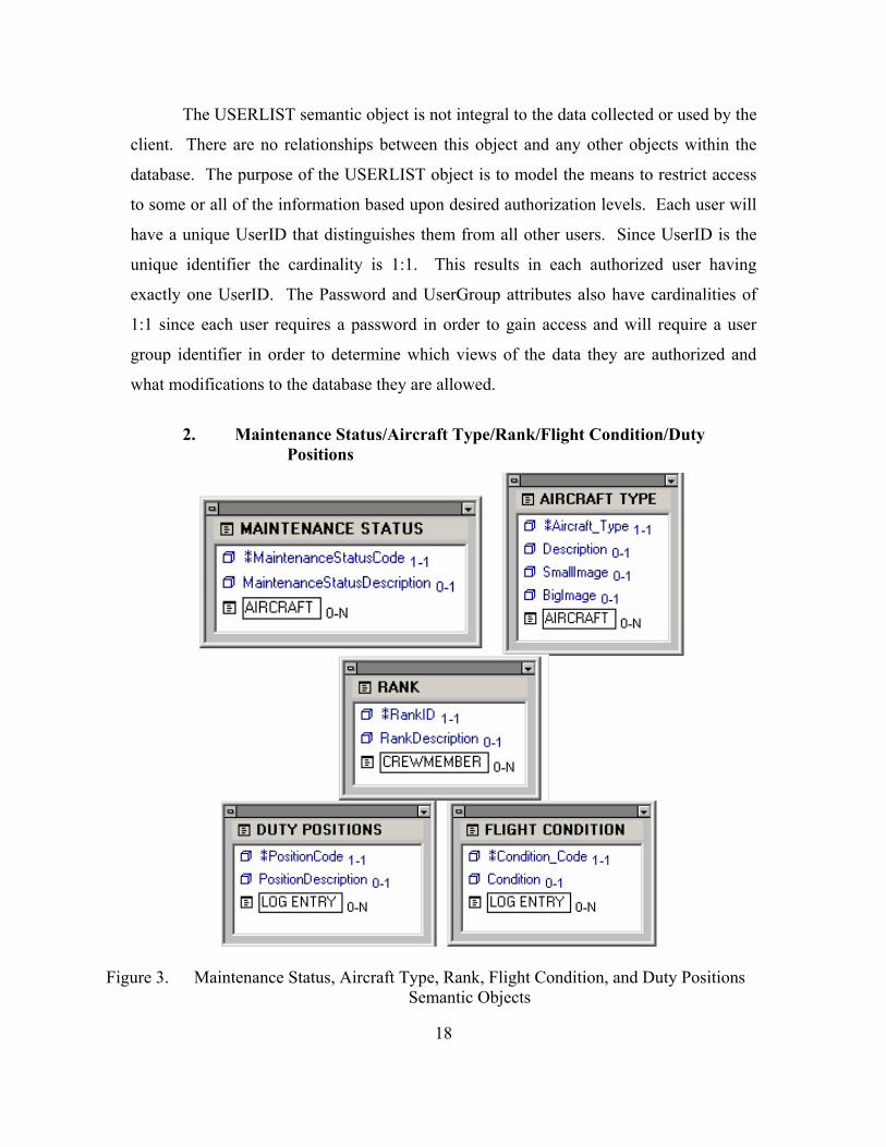
2. Maintenance Status/Aircraft Type/Rank/Flight Condition/Duty
Positions
Figure 3. Maintenance Status, Aircraft Type, Rank, Flight Condition, and Duty Positions Semantic Objects

19
Each of these semantic objects serve the sole purpose of providing enumerated
lists for attributes of other semantic objects in the model. These objects are used to
populate menus that ensure data is entered into the database in a consistent manner. Each
table has an abbreviated code that is the unique identifier for the object with a cardinality
of 1:1 since the unique identifier is required for each instance. Each object also has an
optional description for each abbreviation. An example instance for the RANK object
would be RankID=”CPT” and RankDescription=”Captain.” Each object also has the
attribute that establishes its relationship with the other objects in the model. These
relationships are all 0.N, or zero to many. For instance, a rank instance can exist in the
table even without any crewmembers in the database that hold that rank, hence the
minimum cardinality of 0; there also could be thousands of crewmembers in the database
that all hold the same rank, hence the maximum cardinality of N. The aircraft object is
the only one of these objects that has additional attributes; these attributes are used to
hold the path to aircraft images that enhance the web interface but are not key to the data
collection or reporting.
3. Crewmember
Figure 4. CREWMEMBER Semantic Object
The CREWMEMBER semantic object models real life flight personnel. The
crewmember object will allow flight training data to be associated with individual

20
crewmembers and the crewmembers with units, and hence the flight data, to be
associated with units. The identifier attribute for this object is PID; this is the same
unique identifier that all crewmembers use in the current information system. It is
composed of the crewmember’s first initial, last initial, and the last four digits of their
social security number. The only other required attribute is Last_Name with a cardinality
of 1.1. SSN, First_Name, and Middle_Initial all have a cardinality of 0.1 since an
individual may not have one of these attributes; if they do have these attributes, only one
is allowed. The First_Name and Middle_Initial fields are long enough to facilitate the
rare instances that individuals have multi-word first names or multiple middle initials.
The UNIT attribute establishes the relationship between the CREWMEMBER
object and the UNIT object. The cardinality is 0.1 since a crewmember may not be
assigned to a unit but can only be assigned to one unit at a given time. The RANK
attribute establishes the relationship with the RANK object, which you will recall is
simply an enumerated list to ensure standardized data entry. The cardinality is 0.1 to
allow a crewmember to be added to the database even if the individual inputting the data
is not aware of the crewmember’s current rank, but limiting the rank to only one entry
since a crewmember cannot simultaneously hold more than one rank. The LOG ENTRY
attribute establishes the relationship between the CREWMEMBER object and the LOG
ENTRY object. The LOG ENTRY object, which will be described later, holds
information about flight duties performed by crewmembers. The cardinality is 0.N since
a crewmember will not have any flight duty information when they are first added to the
database, but eventually may have hundreds or thousands of log entries.
21
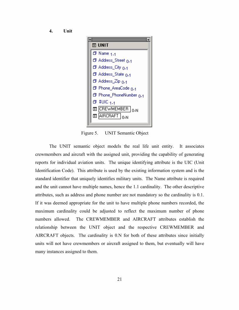
4. Unit
Figure 5. UNIT Semantic Object
The UNIT semantic object models the real life unit entity. It associates
crewmembers and aircraft with the assigned unit, providing the capability of generating
reports for individual aviation units. The unique identifying attribute is the UIC (Unit
Identification Code). This attribute is used by the existing information system and is the
standard identifier that uniquely identifies military units. The Name attribute is required
and the unit cannot have multiple names, hence the 1.1 cardinality. The other descriptive
attributes, such as address and phone number are not mandatory so the cardinality is 0.1.
If it was deemed appropriate for the unit to have multiple phone numbers recorded, the
maximum cardinality could be adjusted to reflect the maximum number of phone
numbers allowed. The CREWMEMBER and AIRCRAFT attributes establish the
relationship between the UNIT object and the respective CREWMEMBER and
AIRCRAFT objects. The cardinality is 0.N for both of these attributes since initially
units will not have crewmembers or aircraft assigned to them, but eventually will have
many instances assigned to them.
22
5. Aircraft
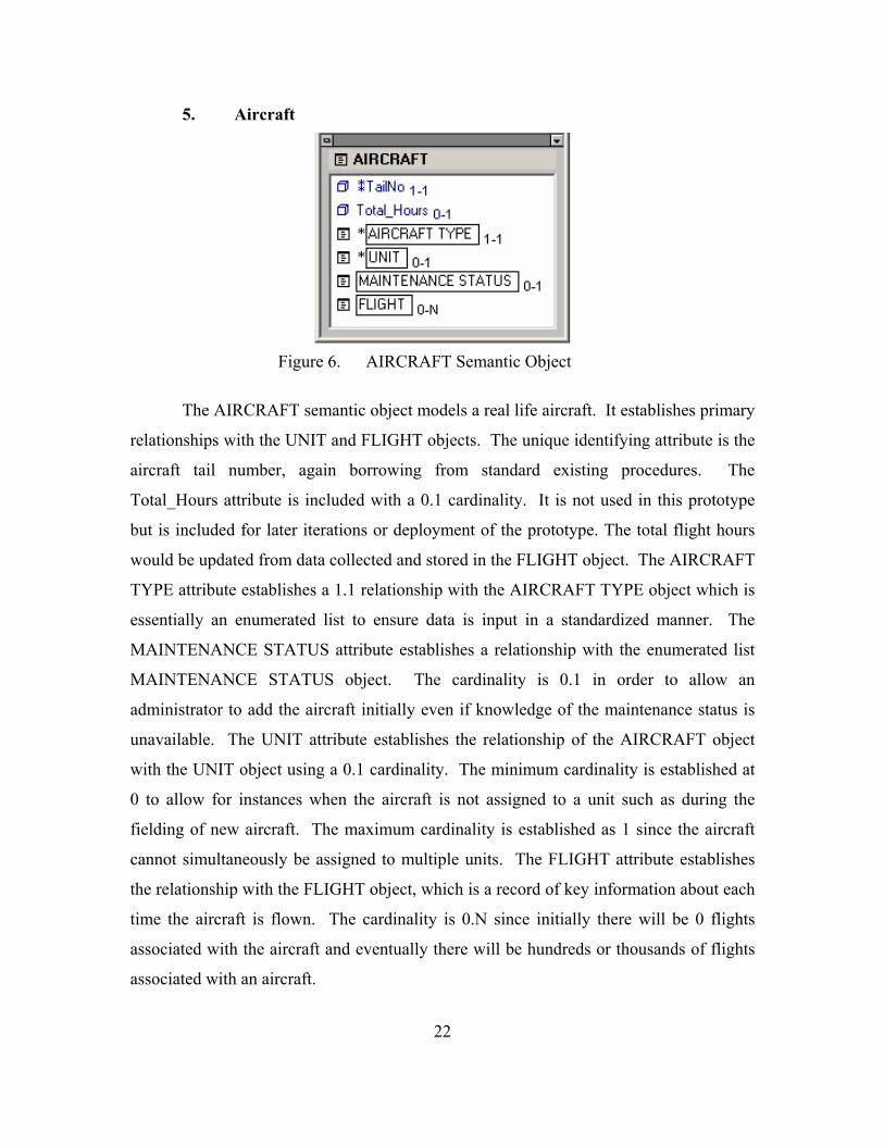
Figure 6. AIRCRAFT Semantic Object
The AIRCRAFT semantic object models a real life aircraft. It establishes primary
relationships with the UNIT and FLIGHT objects. The unique identifying attribute is the
aircraft tail number, again borrowing from standard existing procedures. The
Total_Hours attribute is included with a 0.1 cardinality. It is not used in this prototype
but is included for later iterations or deployment of the prototype. The total flight hours
would be updated from data collected and stored in the FLIGHT object. The AIRCRAFT
TYPE attribute establishes a 1.1 relationship with the AIRCRAFT TYPE object which is
essentially an enumerated list to ensure data is input in a standardized manner. The
MAINTENANCE STATUS attribute establishes a relationship with the enumerated list
MAINTENANCE STATUS object. The cardinality is 0.1 in order to allow an
administrator to add the aircraft initially even if knowledge of the maintenance status is
unavailable. The UNIT attribute establishes the relationship of the AIRCRAFT object
with the UNIT object using a 0.1 cardinality. The minimum cardinality is established at
0 to allow for instances when the aircraft is not assigned to a unit such as during the
fielding of new aircraft. The maximum cardinality is established as 1 since the aircraft
cannot simultaneously be assigned to multiple units. The FLIGHT attribute establishes
the relationship with the FLIGHT object, which is a record of key information about each
time the aircraft is flown. The cardinality is 0.N since initially there will be 0 flights
associated with the aircraft and eventually there will be hundreds or thousands of flights
associated with an aircraft.
23
6. Flight
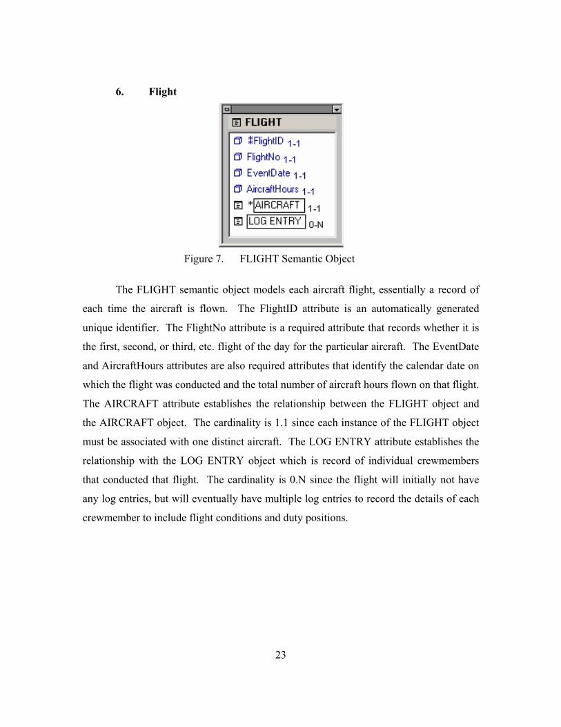
Figure 7. FLIGHT Semantic Object
The FLIGHT semantic object models each aircraft flight, essentially a record of
each time the aircraft is flown. The FlightID attribute is an automatically generated
unique identifier. The FlightNo attribute is a required attribute that records whether it is
the first, second, or third, etc. flight of the day for the particular aircraft. The EventDate
and AircraftHours attributes are also required attributes that identify the calendar date on
which the flight was conducted and the total number of aircraft hours flown on that flight.
The AIRCRAFT attribute establishes the relationship between the FLIGHT object and
the AIRCRAFT object. The cardinality is 1.1 since each instance of the FLIGHT object
must be associated with one distinct aircraft. The LOG ENTRY attribute establishes the
relationship with the LOG ENTRY object which is record of individual crewmembers
that conducted that flight. The cardinality is 0.N since the flight will initially not have
any log entries, but will eventually have multiple log entries to record the details of each
crewmember to include flight conditions and duty positions.

24
7. Log Entry
Figure 8. LOG ENTRY Semantic Object
The LOG ENTRY semantic object models each grouping of crewmember data
associated with an individual flight as an entity. The LogID attribute is an automatically
generated unique identifier. A separate log entry is required for each combination of
Flight Condition, Duty Position, and Crewmember. The Hours attribute is required and
applies only to the individual log entry and may not be the same as the aircraft hours for
the entire flight. The FLIGHT attribute establishes the relationship with the FLIGHT
object, the cardinality is 1.1 since each log entry must be associated with one distinct
flight. The FLIGHT CONDITION and DUTY POSITIONS attributes establish the
relationships with their respective enumerated list objects to ensure data is entered
uniformly. The CREWMEMBER attribute establishes the relationship with the
CREWMEMBER object, the cardinality is 1.1 since each log entry must have a distinct
crewmember.
D. PROTOTYPE DATABASE SCHEMA
A good semantic object model makes the creation of a schema a very simple and
mechanical process. Many modeling tools will automatically create the database or the
designer can use the model to manually create the tables and relationships in the
database. An easy to use semantic object model tool that provides the capability to build
the model, generate a schema from the model, and even reverse engineer a model from an
existing database is Tabledesigner. A trial version of Tabledesigner is available for
25
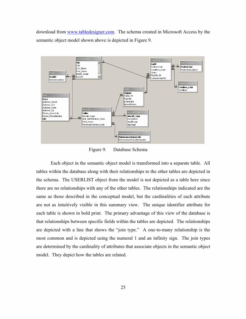
download from www.tabledesigner.com. The schema created in Microsoft Access by the
semantic object model shown above is depicted in Figure 9.
Figure 9. Database Schema
Each object in the semantic object model is transformed into a separate table. All
tables within the database along with their relationships to the other tables are depicted in
the schema. The USERLIST object from the model is not depicted as a table here since
there are no relationships with any of the other tables. The relationships indicated are the
same as those described in the conceptual model, but the cardinalities of each attribute
are not as intuitively visible in this summary view. The unique identifier attribute for
each table is shown in bold print. The primary advantage of this view of the database is
that relationships between specific fields within the tables are depicted. The relationships
are depicted with a line that shows the “join type.” A one-to-many relationship is the
most common and is depicted using the numeral 1 and an infinity sign. The join types
are determined by the cardinality of attributes that associate objects in the semantic object
model. They depict how the tables are related.
26
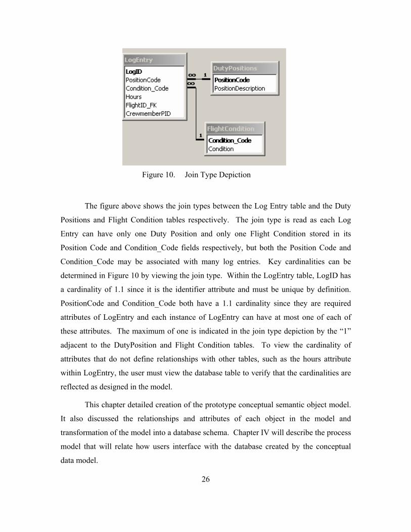
Figure 10. Join Type Depiction
The figure above shows the join types between the Log Entry table and the Duty
Positions and Flight Condition tables respectively. The join type is read as each Log
Entry can have only one Duty Position and only one Flight Condition stored in its
Position Code and Condition_Code fields respectively, but both the Position Code and
Condition_Code may be associated with many log entries. Key cardinalities can be
determined in Figure 10 by viewing the join type. Within the LogEntry table, LogID has
a cardinality of 1.1 since it is the identifier attribute and must be unique by definition.
PositionCode and Condition_Code both have a 1.1 cardinality since they are required
attributes of LogEntry and each instance of LogEntry can have at most one of each of
these attributes. The maximum of one is indicated in the join type depiction by the “1”
adjacent to the DutyPosition and Flight Condition tables. To view the cardinality of
attributes that do not define relationships with other tables, such as the hours attribute
within LogEntry, the user must view the database table to verify that the cardinalities are
reflected as designed in the model.
This chapter detailed creation of the prototype conceptual semantic object model.
It also discussed the relationships and attributes of each object in the model and
transformation of the model into a database schema. Chapter IV will describe the process
model that will relate how users interface with the database created by the conceptual
data model.

27
IV. PROCESS MODEL
This chapter describes the process flow that users of the system will experience
when they access the prototype. The initial process flow and subsequent process flows
are discussed. A logical intuitive flow is the primary consideration in designing the
prototype applications.
This chapter is organized as follows. Section A describes the initial process flow
that all users will follow upon successfully logging into the prototype portal; Section B
describes the aircraft process flow which allows the user to view, add, update or delete
flight information; Section C describes the crewmember process flow which allows users
to view, add or update crewmember information; and Section D describes the report
process flow which allows the generation of tailorable crewmember and unit training
reports, aircraft flight hour reports and aircraft status reports.
The process model is independent of the data model. It provides a structured flow
that allows control of the data views and data modification capabilities that are provided
to each user. In order to describe the process flow, I have broken it down into an initial
flow that all users will see each time they access the Web application and then into
separate process flows for each major sub-process.

28
A. INITIAL PROCESS FLOW
Database
Intro
Try again?
Log in Home
InvalidLog in
UserIDExists
Register
Try again?
Submit
Submit
Register?
Home?
CrewmemberAircraft
Add CrewReports
Control FlowData Flow
AddRecord
See Crewmember FlowSee Aircraft Flow
See Crewmember FlowSee Reports Flow
Initial Process Flow
CheckUser
Figure 11. Initial Website Process Flow
1. Welcome Screen The initial welcome screen identifies the prototype to the user and provides the
user access to the user authentication page.
2. User Authentication The log-in page allows registered users to authenticate themselves to the site
using their UserID and password. Each user is assigned a user group by an administrator.
The user group will provide or restrict access to certain pages and functions based upon
that user group’s privileges. The UserID and password are checked against the user list
in the database. If the user is found in the database and the correct password is entered,
the user will be allowed access to the prototype homepage which is the launching point
for all other process flows. When a user enters an invalid UserID and password

29
combination, he will be directed to a page that advises them that his log-in attempt was
invalid and offers him the option to retry his log-in. The log-in page also provides the
ability for new users to register for limited access.
3. Registration The new user registration page allows users to select a UserID and a password.
The password must be entered twice for validation. When the registration is submitted, a
form validation procedure checks to ensure that both password fields are identical. If the
password fields do not match, the user will be given the opportunity to retype the
passwords. Once the form is submitted, the requested UserID is checked against the list
of currently registered users. If the UserID already exists the user can elect to return to
the registration page in order to register with a different UserID. The default user group
is automatically assigned to each user upon successful registration to provide the ability
to view selected data within the site. Upon successful registration, the user is redirected
to the log-in page. An administrator can change the user group to Crew, Commander, or
Administrator in order to allow access to the appropriate data views and data
modification capability.
4. Portal Home The portal homepage is the launching point for all data views and data input
functions. All pages from this point forward include a standard layout that features a
navigation bar with links to each major sub-process and a link back to this portal home
page. A log-out link is provided at the top of each page. The sub-process links include
Aircraft, Crewmember, Add Crewmember, and Reports. The Add Crewmember link is
part of the overall Crewmember process flow, but is provided to reduce the number of
steps required when a new crewmember is being added that the user knows is not already
in the system. The body of the portal home also includes a brief description of the
functionality available within each sub-process and a direct link to those processes.

30
B. AIRCRAFT PROCESS FLOW The aircraft process flow is entered through the portal home page through either
the navigation bar or through the link within the body of the portal home. The initial
entry page within the aircraft process is always the aircraft search page since all views
and data input are related to an individual aircraft.
Database
Search Results Aircraft Detail
Submit
Control FlowData Flow
From InitialProcess Flow
Aircraft Process Flow
Insert Update Search
Flight Detail
Edit Add Log Done
UpdateStatus
Submit
AddFlight
Submit
Confirm
Submit
EditFlight
Submit
Confirm
Add Log
Add LogEntry
Submit
UpdateRecord
Edit
AddRecord
UpdateRecord
Cxl/Delete
DeleteRecord
AddRecord
Delete
Confirm
Edit
Edit LogEntry
Submit
Submit
ConfirmEntry
Add Log
Add MoreLog
Entries
Submit
AddRecord
UpdateRecord
Figure 12. Aircraft Process Flow
1. Aircraft Search and Results
The aircraft search page allows the user to search for aircraft by the aircraft
model, the unit to which the aircraft is assigned, or both. Conducting the search on “Any
Model” and “Any Unit” will return all aircraft in the database. The searches are
simplified by populating drop-down menus with all of the aircraft models and aviation
units currently in the database.

31
The aircraft results page displays all aircraft that meet the search criteria as well
as a visual display of what criteria were submitted for the search. The search results are
sorted by aircraft tail number and displayed three records per page with navigation
buttons to allow navigation through the results of the search. Each aircraft can be
selected to provide the user a detailed view of data specific to that aircraft.
2. Aircraft Detail The aircraft detail page displays the aircraft model, an image of the aircraft
model, the aircraft tail number, unit to which the aircraft is assigned, current maintenance
status and all flights associated with that aircraft. The options available to the user
include:
a. Record a New Flight This option is restricted to the Crew, Commander, and Administrator user
groups. It allows users to record all relevant information about each aircraft flight.
Selecting this option will direct the user to an add flight dialog page. The user selects the
date of the flight using a calendar menu that ensures the date is added in the proper
format, the flight number, and the total aircraft hours for the flight. When the form is
submitted, the flight is recorded and the user is presented with a confirmation page that
displays the flight information that was submitted. This confirmation page allows the
user to verify the information and proceed to the add log entry page or proceed to an edit
page to correct the flight data and then loop back to this confirmation page.
Once the flight data is confirmed the user is directed to an initial add log
entry page, which is restricted to the Crew, Commander, and Administrator user groups.
Users are required to either add the details for the first log entry (Crewmember, Duty
Position, Flight Condition and Hours) or to cancel the add log entry process. Since at
least one log entry is required for each flight, canceling the log entry process at this point
will delete the flight record. To prevent accidental deletion, the user is directed to a
confirmation page where they must confirm that they desire to delete the flight record or
else return to the add log entry process. Once the first crewmember has been added to the

32
flight, the user is directed to the flight detail page that displays the flight information and
log entries. Additional log entries can be added from this detail page with a similar
process. The only exception is that the flight record will not be deleted if the add log
entry procedure is aborted. The flight detail page will be discussed in greater detail
below.
b. Update Maintenance Status of Selected Aircraft This option which is restricted to the Crew, Commander, and
Administrator user groups, allows users to modify the current maintenance status of the
aircraft. The user is directed to an update page where the maintenance status is selected
from a menu populated by the acceptable status options in the database. Once the new
maintenance status is selected and the form submitted, the user is returned to the aircraft
detail page which will reflect the updated status.
c. Search for a Different Aircraft This option is a quick link back to the aircraft search page and is primarily
used when the user is finished working with the current aircraft. The user can also use
the navigation bar to return to the aircraft search page.
d. View Flight Details The flight details of all existing flights for the aircraft are displayed on the
aircraft detail page with the most recent flights shown first. Three records are displayed
per page with navigation buttons to allow navigation through the remaining list of flights.
Each flight can be selected to view the details of that flight.
3. Flight Detail The flight detail page displays the aircraft tail number, date of flight, flight
number, aircraft hours, and log entries associated with that flight. The options available
to the user include:

33
a. Edit Flight Mission Data This option, which is restricted to the Crew, Commander, and
Administrator user groups, displays the edit flight process that was discussed during the
add flight process. Upon submission of the updated flight data, the user is returned to the
flight detail page which will display the updated flight data.
b. Add Log Entry to Flight This option, which is restricted to the Crew, Commander, and
Administrator user groups, directs the user to an add log entry page that displays the
flight data. The user selects the crewmember, flight condition and duty position from
drop-down menus and manually enters the hours. The user can abort the entry which will
return the flight detail page without adding a log entry or submit the log entry, returning
the flight detail page with the new entry reflected.
c. Flight Entry Complete This option provides a quick link back to the aircraft details page once the
user has finished adding or editing the flight and log entry data.
d. Edit Log Entry This option, which is restricted to the Crew, Commander, and
Administrator user groups, allows the user to select any of the existing log entries and
directs the user to an edit log entry page. The user has the same drop-down options as the
add log entry page. After submitting the modifications the user is returned to the flight
detail page. The user also has the option to abort the edit log entry process or delete the
log entry from within the edit log entry page.
C. CREWMEMBER PROCESS FLOW
The crewmember process flow is entered through the portal home page through
either the navigation bar or through the link within the body of the portal home. The

34
initial entry page within the crewmember process is the crewmember search page unless
the user elects to enter the add crewmember process directly from the project portal.
Database
Search Results Crewmember Detail
Submit
Control FlowData Flow
From InitialProcess Flow
Crewmember Process Flow
Edit Delete
AddCrew
Submit
EditCrew
Submit
DeleteCrew
Cancel
Delete
DeleteRecord
AddRecord Update
Record
Reset
From InitialProcess Flow
Figure 13. Crewmember Process Flow
1. Search
The crewmember search page allows the user to search for crewmembers by rank,
the unit to which the crewmember is assigned, or both. Conducting the search on “Any
Rank” and “Any Unit” will return all crewmembers in the database. The searches are
simplified by populating drop-down menus with all of the ranks and aviation units
currently in the database.
The crewmember results page displays all crewmembers that meet the search
criteria as well as a visual display of what criteria were submitted for the search. The
search results are sorted alphabetically by last name and displayed three records at a time

35
with navigation buttons to allow navigation through the results of the search. Each
crewmember can be selected to provide the user a detailed view of data specific to that
crewmember.
2. Crewmember Detail The crewmember detail page displays the crewmember rank, complete name, unit
assigned, and PID. The social security number is not displayed in order to comply with
the Privacy Act. The options available to the user include:
a. Edit Crewmember Information This option, which is restricted to the Commander and Administrator user
groups, allows users to update crewmember data to include social security number. The
PID cannot be updated since it is used as the unique identifier that links the crewmember
to log entries. After submitting the updates, the user is returned to the crewmember detail
page which will reflect the new data.
b. Delete Crewmember Record This option which is restricted to the Administrator user group, allows
administrators to delete a crewmember. This action would normally be conducted only
when a crewmember was added erroneously. After an administrator deletes a
crewmember record, they are redirected to the crewmember search page.
3. Add Crewmember
This option, which is restricted to the Commander and Administrator user groups,
is accessed directly from the portal home page. The user is provided with drop-down
menus for rank and unit, the remaining fields must be manually entered. Upon
submission of the crewmember data, the user is redirected to the crewmember search
page.
36
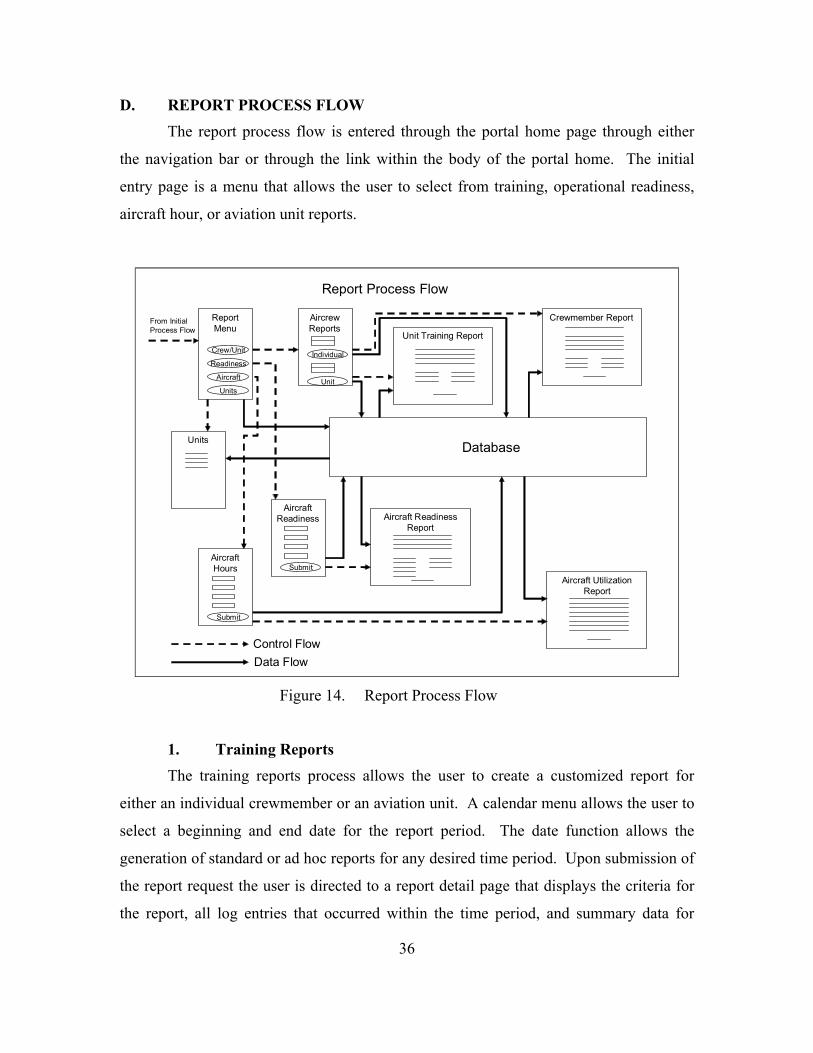
D. REPORT PROCESS FLOW The report process flow is entered through the portal home page through either
the navigation bar or through the link within the body of the portal home. The initial
entry page is a menu that allows the user to select from training, operational readiness,
aircraft hour, or aviation unit reports.
Database
ReportMenu
AircrewReports
Unit Training Report
Aircraft
Control FlowData Flow
From InitialProcess Flow
Report Process Flow
Unit
Readiness
Crew/Unit Individual
Crewmember Report
AircraftReadiness
SubmitAircraftHours
Submit
Aircraft ReadinessReport
Aircraft UtilizationReport
Units
Units
Figure 14. Report Process Flow
1. Training Reports The training reports process allows the user to create a customized report for
either an individual crewmember or an aviation unit. A calendar menu allows the user to
select a beginning and end date for the report period. The date function allows the
generation of standard or ad hoc reports for any desired time period. Upon submission of
the report request the user is directed to a report detail page that displays the criteria for
the report, all log entries that occurred within the time period, and summary data for
37
flight conditions, duty positions, and total flight time. The log entries are also user
sortable for each attribute of the log entry.
2. Maintenance/Aircraft Readiness The readiness report process allows the user to generate a current maintenance
report based upon an individual aircraft tail number, a specific aviation unit, or an aircraft
model. Upon submission of the report request, the user is directed to a report detail page
that displays the criteria for the report, all aircraft that meet the criteria of the report, and
summary data reflecting the number and percent of aircraft that are in each maintenance
status. The results are also user sortable by tail number, aviation unit, and maintenance
status.
3. Aircraft Utilization The aircraft utilization report process allows the user to create a customized report
for an individual tail number, aviation unit, or aircraft model. A calendar menu allows
the user to select a beginning and end date for the report period. The date function allows
the generation of standard or ad hoc reports for any desired time period. Upon
submission of the report request the user is directed to a report detail page that displays
the criteria for the report, all aircraft flights that occurred within the time period, and the
total flight time for all flights. The flights are also user sortable by date, tail number,
aviation unit, and flight hours.
4. Aviation Units The unit report process allows users to view all aviation units. The user is
directed to a detail page that depicts key unit information. The units are sorted
alphabetically by unit name and displayed three units at a time with navigation buttons to
allow navigation through all aviation units included in the database.

38
This chapter described the process flow model that provides the basis for building
the prototype user interface. At this point everything necessary to create the prototype is
completed. Chapter V will discuss considerations for implementation and deployment of
the prototype.
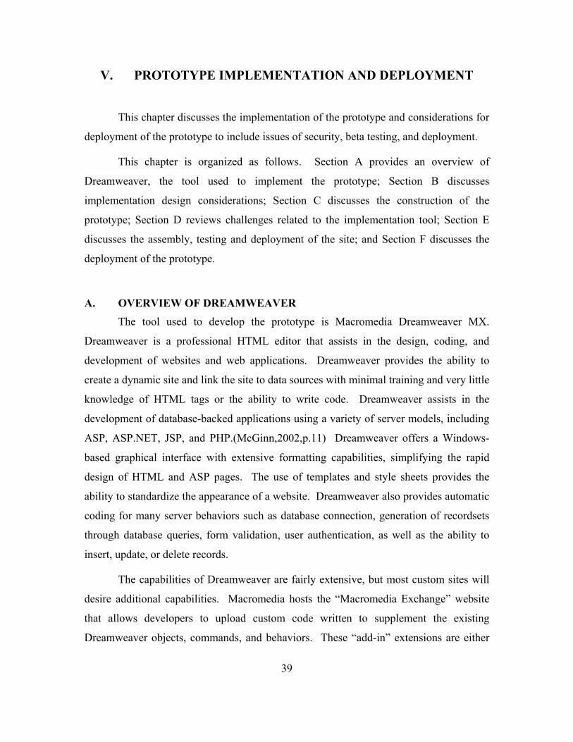
39
V. PROTOTYPE IMPLEMENTATION AND DEPLOYMENT
This chapter discusses the implementation of the prototype and considerations for
deployment of the prototype to include issues of security, beta testing, and deployment.
This chapter is organized as follows. Section A provides an overview of
Dreamweaver, the tool used to implement the prototype; Section B discusses
implementation design considerations; Section C discusses the construction of the
prototype; Section D reviews challenges related to the implementation tool; Section E
discusses the assembly, testing and deployment of the site; and Section F discusses the
deployment of the prototype.
A. OVERVIEW OF DREAMWEAVER The tool used to develop the prototype is Macromedia Dreamweaver MX.
Dreamweaver is a professional HTML editor that assists in the design, coding, and
development of websites and web applications. Dreamweaver provides the ability to
create a dynamic site and link the site to data sources with minimal training and very little
knowledge of HTML tags or the ability to write code. Dreamweaver assists in the
development of database-backed applications using a variety of server models, including
ASP, ASP.NET, JSP, and PHP.(McGinn,2002,p.11) Dreamweaver offers a Windows-
based graphical interface with extensive formatting capabilities, simplifying the rapid
design of HTML and ASP pages. The use of templates and style sheets provides the
ability to standardize the appearance of a website. Dreamweaver also provides automatic
coding for many server behaviors such as database connection, generation of recordsets
through database queries, form validation, user authentication, as well as the ability to
insert, update, or delete records.
The capabilities of Dreamweaver are fairly extensive, but most custom sites will
desire additional capabilities. Macromedia hosts the “Macromedia Exchange” website
that allows developers to upload custom code written to supplement the existing
Dreamweaver objects, commands, and behaviors. These “add-in” extensions are either

40
free or charge a nominal fee to download. Common custom extensions include pop-up
calendars and enhanced form validation. Dreamweaver also allows developers to readily
include their own custom code and debug it directly in Dreamweaver.
B. IMPLEMENTATION DESIGN CONSIDERATIONS Design considerations include appearance, colors, fonts, and navigation. The
design should focus on ease of use and functionality. Colors and fonts used should be
appealing and appropriate to the target audience or users. Graphics and flashy layout
may be added when they enhance the appeal or usability of the site, but should be
avoided if they detract from the sites utility or hinder performance. It is helpful to know
the normal access mode and minimum expected connection speed of the site users. If a
broadband connection is the normal mode, graphics that enhance the site are helpful;
however, if a dial-up connection is the normal usage mode, only essential graphics should
be included. Macromedia Fireworks is a good image editor that allows editing of images
from within Dreamweaver. Fireworks allows the designer to save the image in a variety
of formats and provides an estimated time to load the image in a web browser based upon
various connection speeds. Another alternative when graphics are desired is to create a
graphical site with a text only version of the site for slower internet connections.
A site should not unnecessarily force users to follow extended link sequences
when it is feasible to simplify the flow. Developers should understand the normal user
workflow for the site and provide direct links to common or recurring pages. When
designing the site, the normal user workflow for each major user group should be
considered. Significant time savings and a professional looking site can be achieved best
by selecting a color scheme and fonts, as well as acquiring or creating all desired images
prior to creating and assigning behaviors to pages. Creating templates that are then used
to create subsequent pages ensures a uniform look and allows future modifications to all
pages by simply updating the template. Style sheets are another useful technology to
provide consistency and rapid design modifications to the site. Specific fonts and colors
can be saved for common items such as links, titles, and body text. These style sheets

41
can then be attached to provide standardized formatting and allow modifications to be
applied to the entire site through updating the style sheet.
C. CONSTRUCTING THE PROTOTYPE Construction of the prototype is not recommended until the images, layout, fonts,
colors, and templates discussed previously have been established. The process flow
model provides an orderly sequential page design sequence to ensure that the desired
variables are passed between pages following the normal user flow. The first pages to
create will generally be the introduction and user authentication pages. These pages may
require a separate template that does not provide links directly into process flows of the
site; an example is shown in Figure 15. These pages can be created, to include
authentication of users and user groups, but applying restrictions to subsequent pages
should be deferred until the site is near completion since the restrictions will prevent the
ability to preview pages from within Dreamweaver during design.
Figure 15. Log-in Template with Dreamweaver workspace view

42
After users log in to the site, sufficient information should be provided to assist
them with navigating the site without unnecessarily cluttering the page (see Figure 16).
Figure 16. eAviation Project Welcome Screen
The primary sequence used in this prototype is Search-Results-Detail. To
construct a search page, specific search criteria must be user selectable and then passed to
the results page. Drop-down menus generated from lookup tables within the database,
ensure that at least one instance of the search attribute exists within the database and
prevents unsuccessful searches and avoids the introduction of typing errors. Figure 17
depicts a typical search page. The results page should display the criteria of the search,
this will require some minor code editing if the search allows any record of a specific
search attribute to be displayed. The built-in Dreamweaver behavior will display the
search variables that were selected, but the wildcard variable “%” that indicates all
records were selected is not meaningful to system users. The designer must create a
record set on the results page that queries the database based upon the criteria passed
from the search page. The results should be limited to the number of records that can be
displayed on a page, similar to Figure 18. Dreamweaver provides the ability to insert
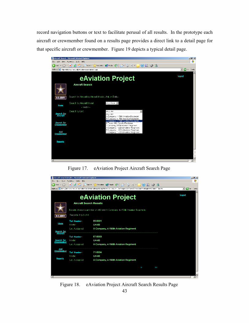
43
record navigation buttons or text to facilitate perusal of all results. In the prototype each
aircraft or crewmember found on a results page provides a direct link to a detail page for
that specific aircraft or crewmember. Figure 19 depicts a typical detail page.
Figure 17. eAviation Project Aircraft Search Page
Figure 18. eAviation Project Aircraft Search Results Page

44
Figure 19. eAviation Project Aircraft Detail Page
Dreamweaver provides built-in behaviors to insert, update and delete records
from the database. Figure 20 depicts a typical insert record page and Figure 21 displays
the application of the behavior in Dreamweaver.

45
Figure 20. eAviation Project Add Flight Record Page
Figure 21. eAviation Project Application of Insert Record Behavior
The creation of a form within the page, along with a “submit” button labeled with
the desired action provides the ability to insert, update, or delete records. When the
desired behavior is selected, Dreamweaver attempts to automatically match the form
elements with the appropriate field in the database table, but also allows the designer to
verify that each field is associated with the appropriate form element. After each page
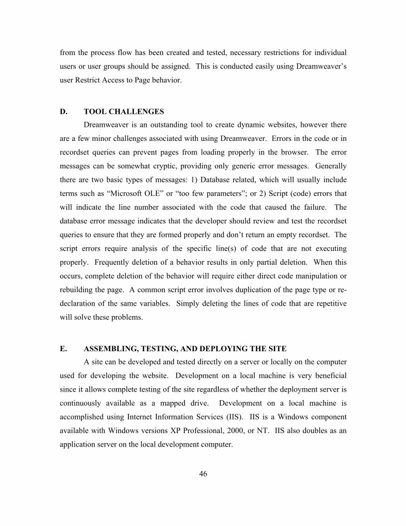
46
from the process flow has been created and tested, necessary restrictions for individual
users or user groups should be assigned. This is conducted easily using Dreamweaver’s
user Restrict Access to Page behavior.
D. TOOL CHALLENGES Dreamweaver is an outstanding tool to create dynamic websites, however there
are a few minor challenges associated with using Dreamweaver. Errors in the code or in
recordset queries can prevent pages from loading properly in the browser. The error
messages can be somewhat cryptic, providing only generic error messages. Generally
there are two basic types of messages: 1) Database related, which will usually include
terms such as “Microsoft OLE” or “too few parameters”; or 2) Script (code) errors that
will indicate the line number associated with the code that caused the failure. The
database error message indicates that the developer should review and test the recordset
queries to ensure that they are formed properly and don’t return an empty recordset. The
script errors require analysis of the specific line(s) of code that are not executing
properly. Frequently deletion of a behavior results in only partial deletion. When this
occurs, complete deletion of the behavior will require either direct code manipulation or
rebuilding the page. A common script error involves duplication of the page type or re-
declaration of the same variables. Simply deleting the lines of code that are repetitive
will solve these problems.
E. ASSEMBLING, TESTING, AND DEPLOYING THE SITE A site can be developed and tested directly on a server or locally on the computer
used for developing the website. Development on a local machine is very beneficial
since it allows complete testing of the site regardless of whether the deployment server is
continuously available as a mapped drive. Development on a local machine is
accomplished using Internet Information Services (IIS). IIS is a Windows component
available with Windows versions XP Professional, 2000, or NT. IIS also doubles as an
application server on the local development computer.

47
Connection to the database can be accomplished by defining a custom connection
string within Dreamweaver that points directly to the database on the testing server. The
other option, which simplifies deployment, is to define a Data Source Name (DSN). A
DSN can be defined using Administrative Tools within the Windows Control Panel.
Defining a DSN with the same name on the deployment server allows uploading the site
to the deployment server without losing database connectivity or requiring modifications
to the website. In order for website users to insert, update, or delete records in the
database, security settings for the database folder and the database must allow internet
users to modify the database.
When developing the site on a local computer, the local folder where the files will
be stored and the location of the testing server must be defined. Figure 22 and 23 depict
the local and testing server set-up.
Figure 22. eAviation Project: Local Site Definition
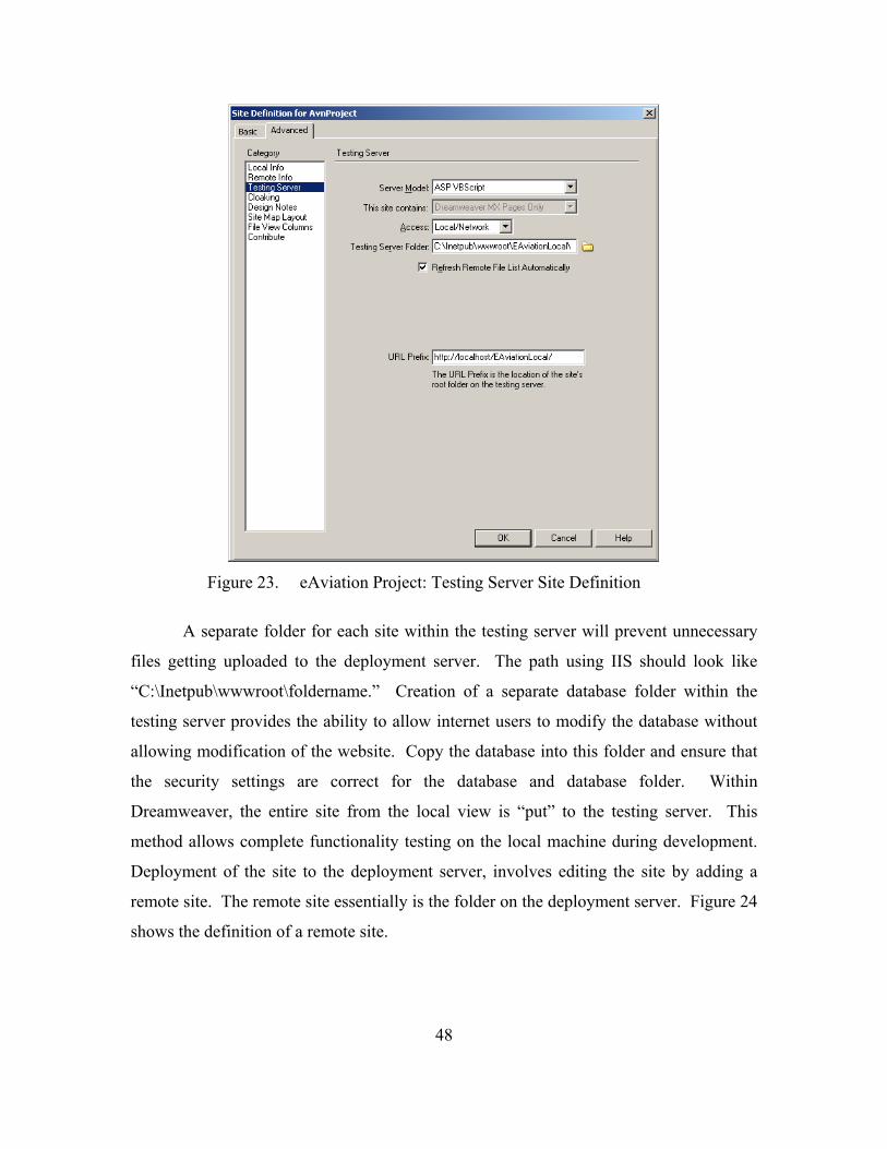
48
Figure 23. eAviation Project: Testing Server Site Definition
A separate folder for each site within the testing server will prevent unnecessary
files getting uploaded to the deployment server. The path using IIS should look like
“C:\Inetpub\wwwroot\foldername.” Creation of a separate database folder within the
testing server provides the ability to allow internet users to modify the database without
allowing modification of the website. Copy the database into this folder and ensure that
the security settings are correct for the database and database folder. Within
Dreamweaver, the entire site from the local view is “put” to the testing server. This
method allows complete functionality testing on the local machine during development.
Deployment of the site to the deployment server, involves editing the site by adding a
remote site. The remote site essentially is the folder on the deployment server. Figure 24
shows the definition of a remote site.
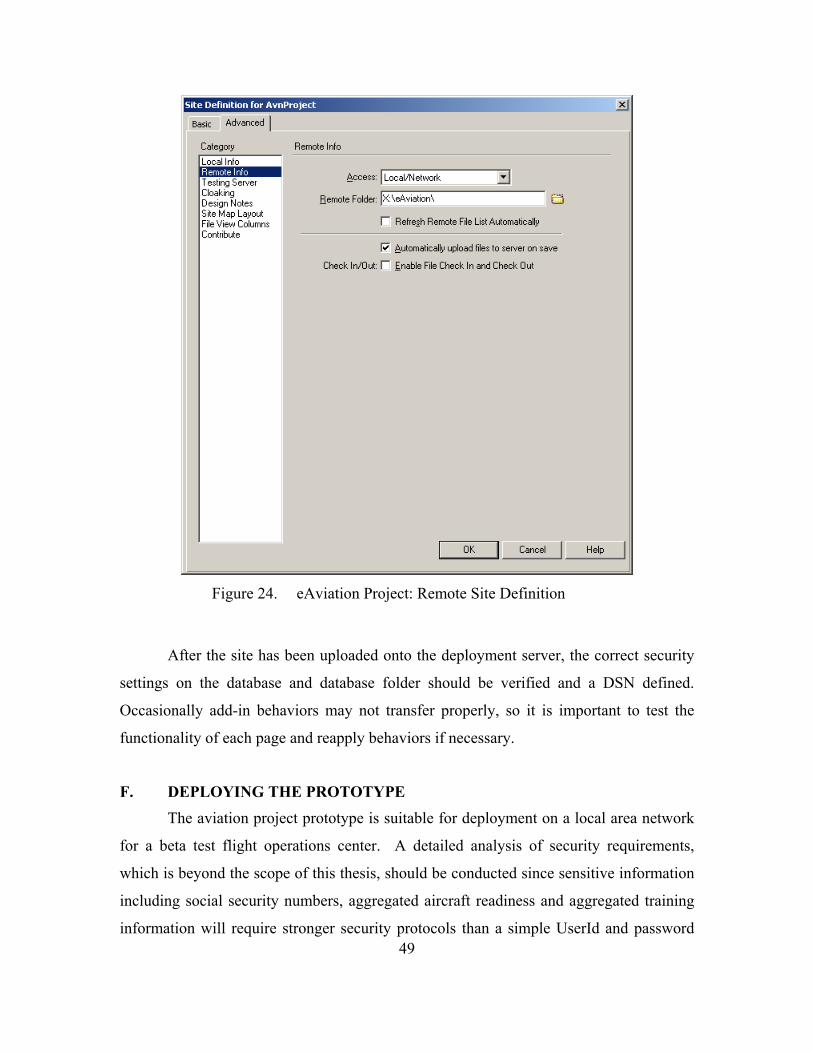
49
Figure 24. eAviation Project: Remote Site Definition
After the site has been uploaded onto the deployment server, the correct security
settings on the database and database folder should be verified and a DSN defined.
Occasionally add-in behaviors may not transfer properly, so it is important to test the
functionality of each page and reapply behaviors if necessary.
F. DEPLOYING THE PROTOTYPE The aviation project prototype is suitable for deployment on a local area network
for a beta test flight operations center. A detailed analysis of security requirements,
which is beyond the scope of this thesis, should be conducted since sensitive information
including social security numbers, aggregated aircraft readiness and aggregated training
information will require stronger security protocols than a simple UserId and password

50
system offers. Secure socket layers is likely to be appropriate. An initial
recommendation to meet internet security requirements is to piggyback onto the security
and authentication used for Army Knowledge Online (AKO). This level of security
should be sufficient as long as the aggregated information remains at an unclassified, For
Official Use Only (FOUO) level. The restriction to beta testing with actual flight data
only on a local area network could be lifted once appropriate security personnel certify
security requirements for use on the internet.
As mentioned above, the first beta version should be tested in flight operations to
allow modifications based upon feedback before conducting a beta test with the flight
crews which will ultimately be the primary individuals conducting data input. The flight
operations is already taking paper copies of flight data and manually entering this data
into their existing system. The number of personnel that will need to be trained on the
prototype beta would be minimal and does not significantly impact the workflow of the
flight operations. A design team representative should be present throughout the initial
beta to capture as much feedback as possible through observing the flight operations
personnel along with conducting interviews. Success of the initial beta is determined by
the ability to generate all currently required unit and crewmember training reports, to
include any ad hoc report requests that occur during the beta. The results of the initial
beta should be used to modify the data and process models for a second beta test.
Prior to the second beta test, an interface between the prototype database and the
maintenance management database should be developed. This will allow an incremental
implementation that keeps the existing maintenance management system fully functional
and allows for potential future expansion of the prototype if desired. With this database
interface in place for the second beta test, this keeps aircrews from experiencing the
prototype beta as an additional requirement. The crewmember will simply begin
conducting data input on the prototype beta with the data feeding directly to the existing
maintenance management system through the database interface and will actually reduce
the workload of the flight operations section since the data they have historically
recorded manually from the paper copy forms the crewmembers complete will be entered
into the prototype directly by the crewmember.

51
During each beta test a separate evaluation of the decision support features should
be conducted. The traditional users of the report information generated by the flight
operations section involved in the beta test would be the initial focus but select
representatives from higher echelon stakeholders would also be included to evaluate
format and ease of use for the decision support reporting capability. A potential future
consideration for designing views of the data could include adding a dashboard type
visual display of the data. The dashboard type display should not require any
modifications to the data model or the database, but could be written exclusively by
conducting appropriate queries of the database.
This chapter described the implementation of the prototype to include tools,
design considerations, challenges, and assembly of the site. Deployment of the prototype
considerations and recommendations were also discussed. Chapter VI will summarize the
project development, draw conclusions, and propose future research.

52
THIS PAGE INTENTIONALLY LEFT BLANK

53
VI. SUMMARY, CONCLUSIONS, AND FUTURE RESEARCH
This chapter summarizes the analysis, modeling and implementation of the
prototype. Conclusions are then drawn about the implementation of this prototype and
are generalized to benefit the development of future web-centric information systems.
The chapter also presents directions for future research opportunities.
This chapter is organized as follows. Section A summarizes the project; Section
B discusses conclusions drawn from the project; and Section C proposes future research
recommendations.
A. SUMMARY This thesis reviewed the existing Army Aviation flight data management process
including its regulatory requirements. The primary area identified for improvement was
the data collection process. The current process has unnecessary redundancies and
significant logistical burdens. A secondary area identified for improvement was the
timely availability of flight data for decision making and report generation. Based upon
these identified areas for improvement, this thesis focused on the development of an
internet-centric information system to replace the data collection process for aircraft and
crewmember flight data combined with customizable queries for decision support.
The development of the prototype web-enabled database along with guidelines for
development was reviewed. This development focused on the conceptual data model,
transformation of the model into a database schema, the process flow model and the
creation of a functional prototype.
Significant potential benefits identified include: 1) Reducing the logistical burden
on unit’s data collection procedures, providing the potential allocation of this time to
aircraft maintenance and primary mission accomplishment; and 2) The ability to provide
tailorable, near real time information about aircraft maintenance status, individual
training, and unit training to decision makers at all levels as a decision support tool.

54
B. CONCLUSIONS The Army has the potential to reduce the man hours currently expended recording
and reporting administrative data, reduce the logistics requirements for collecting
aviation flight data and provide near real time visibility of training and maintenance to
any desired echelon of command in tailorable views.
The reduction in time spent entering data would allow the crewmembers time to
be allocated to aircraft maintenance providing higher aircraft availability to conduct
training and actual missions. It also can reduce the opportunities for inducing errors
through manual transcription of data. The common entry point for data used in
maintenance management and flight training also eliminates discrepancies between the
two systems.
The internet based data collection system reduces the logistical burden on flight
units by aggregating the software and hardware at central locations. This provides the
capability of upgrading the system without the necessity of physically upgrading the data
input or processing devices at the flight unit. The need for additional notebook
computers is eliminated, allowing existing computing devices with a web browser to
fulfill that role. This further reduces the need for spare notebooks, lengthy data transfer
processes and technicians to troubleshoot problems with the existing notebook
computers.
The near real time aggregation of flight data in a centralized database will allow
queries at each echelon of supervision. The benefits of this are twofold; the information
is available when needed for decision making purposes and the flight company is not
tasked with excessive report generation requirements when ad hoc reports are deemed
necessary. The near real time availability of information about both training and
maintenance will allow trend analysis and the ability to address issues in a timelier
manner along with providing details needed to make decisions about unit employment.
The flight operations and flight company leadership would spend considerably less time
responding to standard and ad hoc report requests, allowing them to focus on leadership
and training.

55
C. FUTURE RESEARCH There are several opportunities for extending this research both related to this
prototype and to web-enabled database development in general. The three primary areas
that I recommend are security, database interfaces, and visual dashboard display.
A detailed analysis of security requirements is needed for DoD website
deployment, specifically focused on the changing requirements as information is
aggregated for decision support. The deployment of this prototype would likely result in
eventually migrating to smaller wireless devices. Research about security needs for
wireless PDA type devices would also be beneficial. Another security related research
opportunity is analyzing the potential of sharing authentication capabilities with existing
DoD portals such as Army Knowledge Online (AKO).
Research about potential interfaces between a prototype web-enabled database
and existing backend systems, such as the maintenance management system, would also
be very useful. This research could specifically focus on selecting strategies for seamless
data flow between the Web and the backend applications.
A very promising area for future research would be designing views of existing
data that can be displayed in a dashboard type visual display. The dashboard type display
could provide a quick visual status with the potential to drill deeper into the data through
queries.

56
THIS PAGE INTENTIONALLY LEFT BLANK

57
LIST OF REFERENCES
Alberts, D.S., Garstka,J.J., and Stein, F.P., Network Centric Warfare: Developing and Leveraging Information Superiority, DoD C4ISR Cooperative Research Program, Washington, D.C., 2d ed (Revised), 1999. Army Regulation 700-138, Army Logistics Readiness and Sustainability, Department of the Army, Washington, D.C., 2004. Army Regulation 95-1, Flight Regulations, Department of the Army, Washington, D.C., 1997. El Sawy, O.A., Redesigning Enterprise Processes for e-Business, McGraw-Hill Irwin, 2001, pp.39-41. Field Manual 3-04.500, Army Aviation Maintenance, Department of the Army, Washington, D.C., 2000. Fontenot, G., Degen, E.G., and Tohn, D., On Point: The United States Army in Operation Iraqi Freedom, Combat Studies Institute Press, 2004. Kroenke, D.M., Database Processing: Fundamentals, Design & Implementation, 8th ed, Prentice Hall, 2002. McGinn, S., Getting Started with Dreamweaver MX, Macromedia Inc., 2002.

58
THIS PAGE INTENTIONALLY LEFT BLANK

59
INITIAL DISTRIBUTION LIST
1. Defense Technical Information Center Ft. Belvoir, Virginia
2. Dudley Knox Library Naval Postgraduate School
Monterey, California
3. Defense Logistics Studies Information Exchange U.S. Army Logistics Management College Fort Lee, Virginia
4. Dr. Dan C. Boger Naval Postgraduate School
Monterey, California 5. Professor Magdi N. Kamel
Naval Postgraduate School Monterey, California 6. Glenn R. Cook
Naval Postgraduate School Monterey, California 7. COL William Crosby
PEO Aviation Redstone Arsenal, Alabama 8. LTC Anthony S. Pelczynski
PEO Aviation Redstone Arsenal, Alabama 9. Mr. Ron Dalton
PEO Aviation Redstone Arsenal, Alabama