HOBO RX3000 Remote Monitoring Station Manual - Alat UjiHOBO® RX3000 Remote Monitoring Station...
18
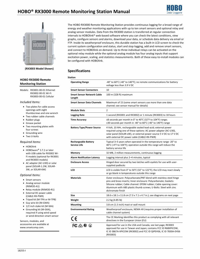
HOBO® RX3000 Remote Monitoring Station Manual 18255-I The HOBO RX3000 Remote Monitoring Station provides continuous logging for a broad range of energy and weather monitoring applications with up to ten smart sensors and optional relay and analog sensor modules. Data from the RX3000 station is transferred at regular connection intervals to HOBOlink® web-based software where you can check the latest conditions, view graphs, configure sensors and alarms, download your data, or schedule data delivery via email or FTP. Inside its weatherproof enclosure, this durable station has a built-in LCD screen to check the current system configuration and status, start and stop logging, add and remove smart sensors, and connect to HOBOlink on demand. Up to three individual relays can be activated on the optional relay module while the optional analog module has four analog inputs that support excitation power, scaling, and statistics measurements. Both of these easy-to-install modules can be configured with HOBOlink. Specifications Station Operating Range -40° to 60°C (-40° to 140°F); no remote communications for battery voltage less than 3.9 V DC Smart Sensor Connectors 10 Smart Sensor Network Cable Length 100 m (328 ft) maximum Smart Sensor Data Channels Maximum of 15 (some smart sensors use more than one data channel; see sensor manual for details) Module Slots 2 Logging Rate 1 second (RX3001 and RX3002) or 1 minute (RX3003) to 18 hours Time Accuracy ±8 seconds per month in 0° to 40°C (32°F to 104°F) range; ±30 seconds per month in -40° to 60°C (-40° to 140°F) range Battery Type/Power Source 4 Volt, 10 AHr, rechargeable sealed lead-acid; external power required using one of these options: AC power adapter (AC-U30), solar panel (SOLAR-xW), or external power source 5 V DC to 17 V DC with external DC power cable (CABLE-RX-PWR) Rechargeable Battery Service Life Typical 3–5 years when operated in the temperature range -20° to 40°C (-4°F to 104°F); operation outside this range will reduce the battery service life Memory 32 MB, 2 million measurements, continuous logging Alarm Notification Latency Logging interval plus 2–4 minutes, typical Enclosure Access Hinged door secured by two latches with eyelets for use with user- supplied padlocks LCD LCD is visible from 0° to 50°C (32° to 122°F); the LCD may react slowly or go blank in temperatures outside this range Materials Outer enclosure: Polycarbonate/PBT blend with stainless steel hinge pins and brass inserts; Inner enclosure: Polycarbonate; Gaskets: Silicone rubber; Cable channel: EPDM rubber; Cable opening cover: Aluminum with ABS plastic thumb screws; U-Bolts: Steel with zinc dichromate finish Size 18.6 x 18.1 x 11.8 cm (7.3 x 7.1 x 4.7 in.); see diagrams on next page Weight 2.2 kg (4.85 lb) Mounting 3.8 cm (1.5 inch) mast or wall mount Environmental Rating Weatherproof enclosure, NEMA 4X (requires proper installation of cable channel system) The CE Marking identifies this product as complying with all relevant directives in the European Union (EU) Approved for use in the USA and Canada, see last page; RX3003 approved for use in Taiwan and Japan; contains FCC ID R68XPICOW, IC ID 3867A-XPICOW (RX3002) and FCC ID QIPEHS6, IC ID 7830A-EHS6 (RX3003) HOBO RX3000 Remote Monitoring Station Models: RX3001-00-01 Ethernet RX3002-00-01 Wi-Fi RX3003-00-01 Cellular Included Items: • Two plates for cable access openings with eight thumbscrews and one wrench • Two rubber cable channels • Rubber plugs • Grease packet • Two mounting plates with four screws • Grounding wire • Two U-bolts Required Items: • HOBOlink • HOBOware® 3.7.2 or later with USB cable for RX3002 Wi- Fi models (optional for RX3001 and RX3003 models) • AC adapter (AC-U30) or solar panel (SOLAR-1.2W, SOLAR- 3W, or SOLAR-6W) Optional Items: • Smart sensors • Analog sensor module (RXMOD-A1) • Relay module (RXMOD-R1) • External DC power cable (CABLE-RX-PWR) • Tripod kit (M-TPA or M-TPB) • Guy wire kit (M-GWA) • 1/2 inch stake kit (M-SKA) • Grounding kit (M-GKA), required if using wind speed or wind direction smart sensor Sensors, modules, and accessories are available at www.onsetcomp.com. (RX3003 Model Shown)
Transcript of HOBO RX3000 Remote Monitoring Station Manual - Alat UjiHOBO® RX3000 Remote Monitoring Station...
HOBO® RX3000 Remote Monitoring Station Manual
18255-I
The HOBO RX3000 Remote Monitoring Station provides continuous logging for a broad range of energy and weather monitoring applications with up to ten smart sensors and optional relay and analog sensor modules. Data from the RX3000 station is transferred at regular connection intervals to HOBOlink® web-based software where you can check the latest conditions, view graphs, configure sensors and alarms, download your data, or schedule data delivery via email or FTP. Inside its weatherproof enclosure, this durable station has a built-in LCD screen to check the current system configuration and status, start and stop logging, add and remove smart sensors, and connect to HOBOlink on demand. Up to three individual relays can be activated on the optional relay module while the optional analog module has four analog inputs that support excitation power, scaling, and statistics measurements. Both of these easy-to-install modules can be configured with HOBOlink.
Specifications Station
Operating Range -40° to 60°C (-40° to 140°F); no remote communications for battery voltage less than 3.9 V DC
Smart Sensor Connectors 10
Smart Sensor Network Cable Length
100 m (328 ft) maximum
Smart Sensor Data Channels Maximum of 15 (some smart sensors use more than one data channel; see sensor manual for details)
Module Slots 2
Logging Rate 1 second (RX3001 and RX3002) or 1 minute (RX3003) to 18 hours
Time Accuracy ±8 seconds per month in 0° to 40°C (32°F to 104°F) range; ±30 seconds per month in -40° to 60°C (-40° to 140°F) range
Battery Type/Power Source 4 Volt, 10 AHr, rechargeable sealed lead-acid; external power required using one of these options: AC power adapter (AC-U30), solar panel (SOLAR-xW), or external power source 5 V DC to 17 V DC with external DC power cable (CABLE-RX-PWR)
Rechargeable Battery Service Life
Typical 3–5 years when operated in the temperature range -20° to 40°C (-4°F to 104°F); operation outside this range will reduce the battery service life
Memory 32 MB, 2 million measurements, continuous logging
Alarm Notification Latency Logging interval plus 2–4 minutes, typical
Enclosure Access Hinged door secured by two latches with eyelets for use with user-supplied padlocks
LCD LCD is visible from 0° to 50°C (32° to 122°F); the LCD may react slowly or go blank in temperatures outside this range
Materials Outer enclosure: Polycarbonate/PBT blend with stainless steel hinge pins and brass inserts; Inner enclosure: Polycarbonate; Gaskets: Silicone rubber; Cable channel: EPDM rubber; Cable opening cover: Aluminum with ABS plastic thumb screws; U-Bolts: Steel with zinc dichromate finish
Size 18.6 x 18.1 x 11.8 cm (7.3 x 7.1 x 4.7 in.); see diagrams on next page
Weight 2.2 kg (4.85 lb)
Mounting 3.8 cm (1.5 inch) mast or wall mount
Environmental Rating Weatherproof enclosure, NEMA 4X (requires proper installation of cable channel system)
The CE Marking identifies this product as complying with all relevant directives in the European Union (EU)
Approved for use in the USA and Canada, see last page; RX3003 approved for use in Taiwan and Japan; contains FCC ID R68XPICOW, IC ID 3867A-XPICOW (RX3002) and FCC ID QIPEHS6, IC ID 7830A-EHS6 (RX3003)
HOBO RX3000 Remote Monitoring Station
Models: RX3001-00-01 Ethernet RX3002-00-01 Wi-Fi RX3003-00-01 Cellular
Included Items: • Two plates for cable access
openings with eight thumbscrews and one wrench
• Two rubber cable channels • Rubber plugs • Grease packet • Two mounting plates with
four screws • Grounding wire • Two U-bolts
Required Items: • HOBOlink • HOBOware® 3.7.2 or later
with USB cable for RX3002 Wi-Fi models (optional for RX3001 and RX3003 models)
• AC adapter (AC-U30) or solar panel (SOLAR-1.2W, SOLAR-3W, or SOLAR-6W)
Optional Items: • Smart sensors • Analog sensor module
(RXMOD-A1) • Relay module (RXMOD-R1) • External DC power cable
(CABLE-RX-PWR) • Tripod kit (M-TPA or M-TPB) • Guy wire kit (M-GWA) • 1/2 inch stake kit (M-SKA) • Grounding kit (M-GKA),
required if using wind speed or wind direction smart sensor
Sensors, modules, and accessories are available at www.onsetcomp.com.
(RX3003 Model Shown)
HOBO RX3000 Remote Monitoring Station Manual
1-800-LOGGERS 2 www.onsetcomp.com
Specifications (continued)
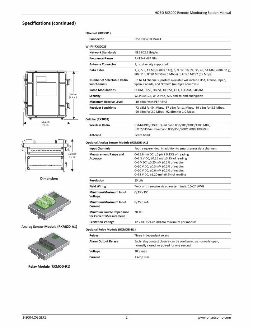
Ethernet (RX3001)
Connector One RJ45/100BaseT
Wi-Fi (RX3002)
Network Standards IEEE 802.11b/g/n
Frequency Range 2.412–2.484 GHz
Antenna Connector 1, no diversity supported
Data Rates 1, 2, 5.5, 11 Mbps (802.11b); 6, 9, 12, 18, 24, 36, 48, 54 Mbps (802.11g);802.11n, HT20 MCS0 (6.5 Mbps) to HT20 MC87 (65 Mbps)
Number of Selectable Radio Subchannels
Up to 14 channels; profiles available will include USA, France, Japan, Spain, Canada, and “Other” (multiple countries)
Radio Modulations OFDM, DSSS, DBPSK, DQPSK, CCK, 16QAM, 64QAM
Security WEP 64/128, WPA-PSK, AES end-to-end encryption
Maximum Receive Level -10 dBm (with PER <8%)
Receiver Sensitivity -72 dBM for 54 Mbps, -87 dBm for 11 Mbps, -89 dBm for 5.5 Mbps, -90 dBm for 2.0 Mbps, -92 dBm for 1.0 Mbps
Cellular (RX3003)
Wireless Radio GSM/GPRS/EDGE: Quad band 850/900/1800/1900 MHz, UMTS/HSPA+: Five band 800/850/900/1900/2100 MHz
Antenna Penta band
Optional Analog Sensor Module (RXMOD-A1)
Input Channels Four, single-ended, in addition to smart sensor data channels
Measurement Range and Accuracy
0–25.6 mA DC, ±5 µA ± 0.15% of reading 0–2.5 V DC, ±0.25 mV ±0.2% of reading 0–5 V DC, ±0.25 mV ±0.2% of reading 0–10 V DC, ±0.3 mV ±0.2% of reading 0–20 V DC, ±0.6 mV ±0.2% of reading 0–33 V DC, ±1.20 mV ±0.2% of reading
Resolution 15 bits
Field Wiring Two- or three-wire via screw terminals, 16–24 AWG
Minimum/Maximum Input Voltage
0/33 V DC
Minimum/Maximum Input Current
0/25.6 mA
Minimum Source Impedance for Current Measurement
20 KΩ
Excitation Voltage 12 V DC ±5% at 200 mA maximum per module
Optional Relay Module (RXMOD-R1)
Relays Three independent relays
Alarm Output Relays Each relay contact closure can be configured as normally open, normally closed, or pulsed for one second
Voltage 30 V max
Current 1 Amp max
Dimensions
Analog Sensor Module (RXMOD-A1)
Relay Module (RXMOD-R1)
11.8 cm 4.7 in.
18.6 cm (7.3 in.)
18.1 cm (7.1 in.)
HOBO RX3000 Remote Monitoring Station Manual
1-800-LOGGERS 3 www.onsetcomp.com
Table of Contents Device Components and Operation ............................................... 3 LCD Operation ................................................................................ 4 Setting up the Station .................................................................... 6
1. Log in to HOBOlink. ............................................................. 6 2. Register the station. ............................................................ 6 3. Install optional modules or user-supplied SIM. ................... 6 4. Plug in the battery and charging device. ............................. 6 5. Check and configure device communications. .................... 6 6. Plug in and search for smart sensors. .................................. 8 7. Connect analog sensors or relay devices. ............................ 8 8. Connect to HOBOlink. ......................................................... 9 9. Configure the station in HOBOlink. ..................................... 9 10. Start logging. ..................................................................... 11
Viewing Data in HOBOlink ............................................................ 11 Setting System and Sensor Alarms ............................................... 12
System Alarms ......................................................................... 12 Sensor Alarms .......................................................................... 12
Starting and Stopping Logging ...................................................... 12 Adding or Removing Smart Sensors ............................................. 13 Adding or Removing Modules ...................................................... 13 Managing Connections to HOBOlink ............................................ 14 Checking Latest Conditions with HOBOware ................................ 14 Deploying and Mounting the Station ........................................... 14
Deployment Guidelines ........................................................... 14 Installing the Grounding Wire ................................................. 15 Mounting the Station .............................................................. 15 Installing the Weatherproof Rubber Cable Channel and Covers15
Care and Maintenance ................................................................. 16 Troubleshooting ........................................................................... 16 Battery Information ..................................................................... 17
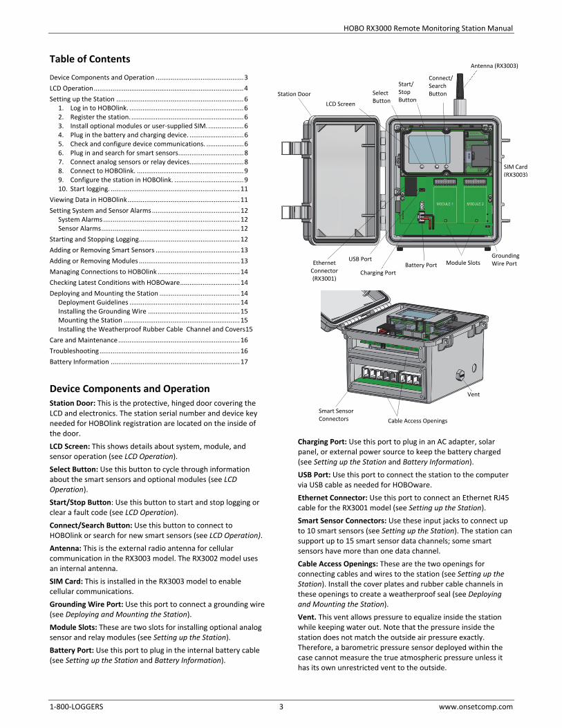
Device Components and Operation Station Door: This is the protective, hinged door covering the LCD and electronics. The station serial number and device key needed for HOBOlink registration are located on the inside of the door. LCD Screen: This shows details about system, module, and sensor operation (see LCD Operation). Select Button: Use this button to cycle through information about the smart sensors and optional modules (see LCD Operation). Start/Stop Button: Use this button to start and stop logging or clear a fault code (see LCD Operation). Connect/Search Button: Use this button to connect to HOBOlink or search for new smart sensors (see LCD Operation). Antenna: This is the external radio antenna for cellular communication in the RX3003 model. The RX3002 model uses an internal antenna. SIM Card: This is installed in the RX3003 model to enable cellular communications. Grounding Wire Port: Use this port to connect a grounding wire (see Deploying and Mounting the Station). Module Slots: These are two slots for installing optional analog sensor and relay modules (see Setting up the Station). Battery Port: Use this port to plug in the internal battery cable (see Setting up the Station and Battery Information).
Charging Port: Use this port to plug in an AC adapter, solar panel, or external power source to keep the battery charged (see Setting up the Station and Battery Information). USB Port: Use this port to connect the station to the computer via USB cable as needed for HOBOware. Ethernet Connector: Use this port to connect an Ethernet RJ45 cable for the RX3001 model (see Setting up the Station). Smart Sensor Connectors: Use these input jacks to connect up to 10 smart sensors (see Setting up the Station). The station can support up to 15 smart sensor data channels; some smart sensors have more than one data channel. Cable Access Openings: These are the two openings for connecting cables and wires to the station (see Setting up the Station). Install the cover plates and rubber cable channels in these openings to create a weatherproof seal (see Deploying and Mounting the Station). Vent. This vent allows pressure to equalize inside the station while keeping water out. Note that the pressure inside the station does not match the outside air pressure exactly. Therefore, a barometric pressure sensor deployed within the case cannot measure the true atmospheric pressure unless it has its own unrestricted vent to the outside.
Smart Sensor Connectors Cable Access Openings
Vent
SIM Card (RX3003)
LCD Screen
Ethernet Connector (RX3001)
Battery Port Charging Port
USB Port Module Slots
Station Door
Grounding Wire Port
Antenna (RX3003)
Connect/ Search Button
Start/ Stop Button
Select Button

HOBO RX3000 Remote Monitoring Station Manual
1-800-LOGGERS 4 www.onsetcomp.com
LCD Operation This example shows all symbols illuminated on the LCD screen with an overview of what each section of the LCD represents. Refer to the table below for details about each section and associated symbols.
System Status This part of the LCD shows the overall system status.
or
When the station is powered up, “Initializing System” flashes in the upper left part of the LCD. After initialization is complete, “System” remains illuminated and one of these symbols will appear:
indicates the system is ok.
indicates there is a problem with the system; check the Device Information panel on your station page in HOBOlink.
Connection Status This part of the LCD shows the communication method used for connecting to HOBOlink and the system connection status.
This indicates the station is connected via a USB cable.
This indicates the station is using Ethernet to connect to HOBOlink. This will blink while connecting to HOBOlink.
This indicates the station is using Wi-Fi to connect to HOBOlink. This also shows the strength of the wireless signal; the more bars there are, the stronger the signal. This will blink while connecting to HOBOlink.
This indicates the station is using a cellular network to connect to HOBOlink. This also shows the strength of the cellular signal; the more bars there are, the stronger the signal. This will blink while connecting to HOBOlink.
or
When the station is attempting to connect or is currently connected to HOBOlink, “Connection” flashes on the LCD. After the connection is complete, “Last Connection” remains illuminated and one of these symbols will appear:
indicates the last connection to HOBOlink was ok.
indicates there was a problem with the last connection; check the Connections log in HOBOlink.
Smart Sensor and Module Status
This part of the LCD shows the status of the smart sensors and any optional modules installed. Module 1 is installed in the left slot and Module 2 in the right slot.
One of the following symbols will also appear next to smart sensors or a module (if applicable):
indicates the smart sensor or module is ok.
indicates there is a problem with the smart sensor or module; check your device page in HOBOlink.
indicates a sensor alarm has tripped and will flash on the LCD until the alarm is cleared; check the Alarms log in HOBOlink.
Logging Status This part of the LCD indicates whether the station is currently logging.
or
“Stopped” indicates the station is not currently logging while “Logging” indicates it is currently logging. Press the Start/Stop button to start or stop logging as desired. Note that “Logging” will blink until the first data point is logged after the Start button is pressed.
Battery and Memory Status
This part of the LCD shows the current battery level and memory.
or
The battery indicator shows the approximate battery power remaining. In this example, the battery is fully charged. The lightning bolt will appear when an AC adapter, solar panel, or external power source is plugged into the station. “Charging” will flash while the battery is being charged.
When the station is logging, it will record data indefinitely, with newest data overwriting the oldest data until the station is stopped. This continuous logging is represented by the arrow in this symbol.
System Status
Connection Status
Smart Sensor and Module Status
Logging Status
Battery and Memory Status
Channel and Device Information
Button Symbols
HOBO RX3000 Remote Monitoring Station Manual
1-800-LOGGERS 5 www.onsetcomp.com
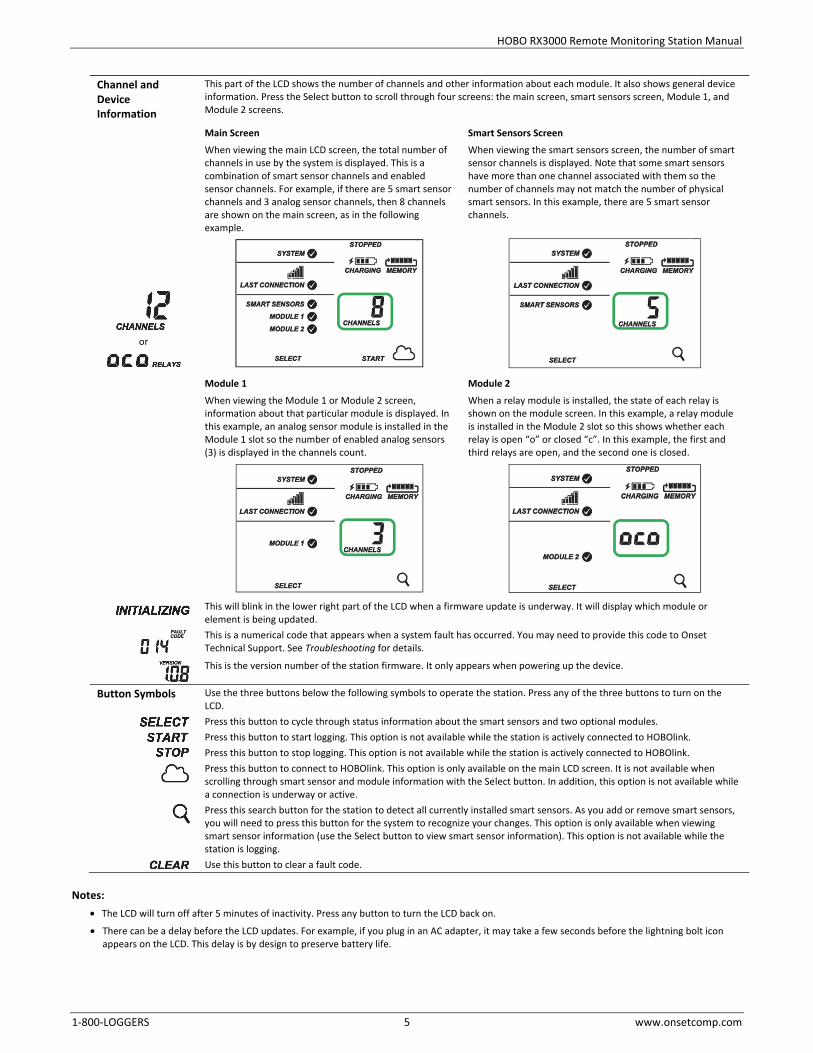
Channel and Device Information
This part of the LCD shows the number of channels and other information about each module. It also shows general device information. Press the Select button to scroll through four screens: the main screen, smart sensors screen, Module 1, and Module 2 screens.
or
Main Screen When viewing the main LCD screen, the total number of channels in use by the system is displayed. This is a combination of smart sensor channels and enabled sensor channels. For example, if there are 5 smart sensor channels and 3 analog sensor channels, then 8 channels are shown on the main screen, as in the following example.
Smart Sensors Screen When viewing the smart sensors screen, the number of smart sensor channels is displayed. Note that some smart sensors have more than one channel associated with them so the number of channels may not match the number of physical smart sensors. In this example, there are 5 smart sensor channels.
Module 1
When viewing the Module 1 or Module 2 screen, information about that particular module is displayed. In this example, an analog sensor module is installed in the Module 1 slot so the number of enabled analog sensors (3) is displayed in the channels count.
Module 2
When a relay module is installed, the state of each relay is shown on the module screen. In this example, a relay module is installed in the Module 2 slot so this shows whether each relay is open “o” or closed “c”. In this example, the first and third relays are open, and the second one is closed.
This will blink in the lower right part of the LCD when a firmware update is underway. It will display which module or element is being updated.
This is a numerical code that appears when a system fault has occurred. You may need to provide this code to Onset Technical Support. See Troubleshooting for details.
This is the version number of the station firmware. It only appears when powering up the device.
Button Symbols Use the three buttons below the following symbols to operate the station. Press any of the three buttons to turn on the LCD.
Press this button to cycle through status information about the smart sensors and two optional modules.
Press this button to start logging. This option is not available while the station is actively connected to HOBOlink.
Press this button to stop logging. This option is not available while the station is actively connected to HOBOlink.
Press this button to connect to HOBOlink. This option is only available on the main LCD screen. It is not available when scrolling through smart sensor and module information with the Select button. In addition, this option is not available while a connection is underway or active.
Press this search button for the station to detect all currently installed smart sensors. As you add or remove smart sensors, you will need to press this button for the system to recognize your changes. This option is only available when viewing smart sensor information (use the Select button to view smart sensor information). This option is not available while the station is logging.
Use this button to clear a fault code. Notes:
• The LCD will turn off after 5 minutes of inactivity. Press any button to turn the LCD back on.
• There can be a delay before the LCD updates. For example, if you plug in an AC adapter, it may take a few seconds before the lightning bolt icon appears on the LCD. This delay is by design to preserve battery life.
HOBO RX3000 Remote Monitoring Station Manual
1-800-LOGGERS 6 www.onsetcomp.com
Setting up the Station Follow these steps to set up the station.
1. Log in to HOBOlink. Go to www.hobolink.com and log in to an existing account or create a new one. You’ll receive an email to activate the new account.
2. Register the station. In HOBOlink, click Devices and then click the Register a Device link. Give the station a name and enter the serial number and device key from the label inside the station door.
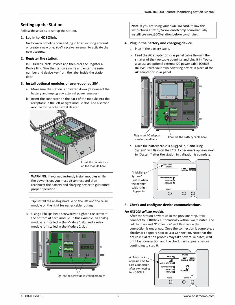
3. Install optional modules or user-supplied SIM. a. Make sure the station is powered down (disconnect the
battery and unplug any external power sources). b. Insert the connector on the back of the module into the
receptacle in the left or right module slot. Add a second module to the other slot if desired.
WARNING: If you inadvertently install modules while the power is on, you must disconnect and then reconnect the battery and charging device to guarantee proper operation.
Tip: Install the analog module on the left and the relay module on the right for easier cable routing.
3. Using a Phillips-head screwdriver, tighten the screw at the bottom of each module. In this example, an analog module is installed in the Module 1 slot and a relay module is installed in the Module 2 slot.
Note: If you are using your own SIM card, follow the instructions at http://www.onsetcomp.com/manuals/ installing-sim-rx3003-station before continuing.
4. Plug in the battery and charging device. a. Plug in the battery cable.
b. Feed the AC adapter or solar panel cable through the smaller of the two cable openings and plug it in. You can also use an optional external DC power cable (CABLE-RX-PWR) with your own powering device in place of the AC adapter or solar panel.
c. Once the battery cable is plugged in, “Initializing System” will flash on the LCD. A checkmark appears next to “System” after the station initialization is complete.
5. Check and configure device communications.
For RX3003 cellular models: After the station powers up in the previous step, it will connect to HOBOlink automatically within two minutes. The cellular icon and “Connection” will flash while the connection is underway. Once the connection is complete, a checkmark appears next to Last Connection. Note that the entire initialization process may take several minutes; wait until Last Connection and the checkmark appears before continuing to step 6.
“Initializing System” flashes when the battery cable is first plugged in
A checkmark appears next to Last Connection after connecting to HOBOlink
Connect the battery cable herePlug in an AC adapter or solar panel here
Insert the connectorson the module here
Tighten the screw on installed modules
HOBO RX3000 Remote Monitoring Station Manual
1-800-LOGGERS 7 www.onsetcomp.com
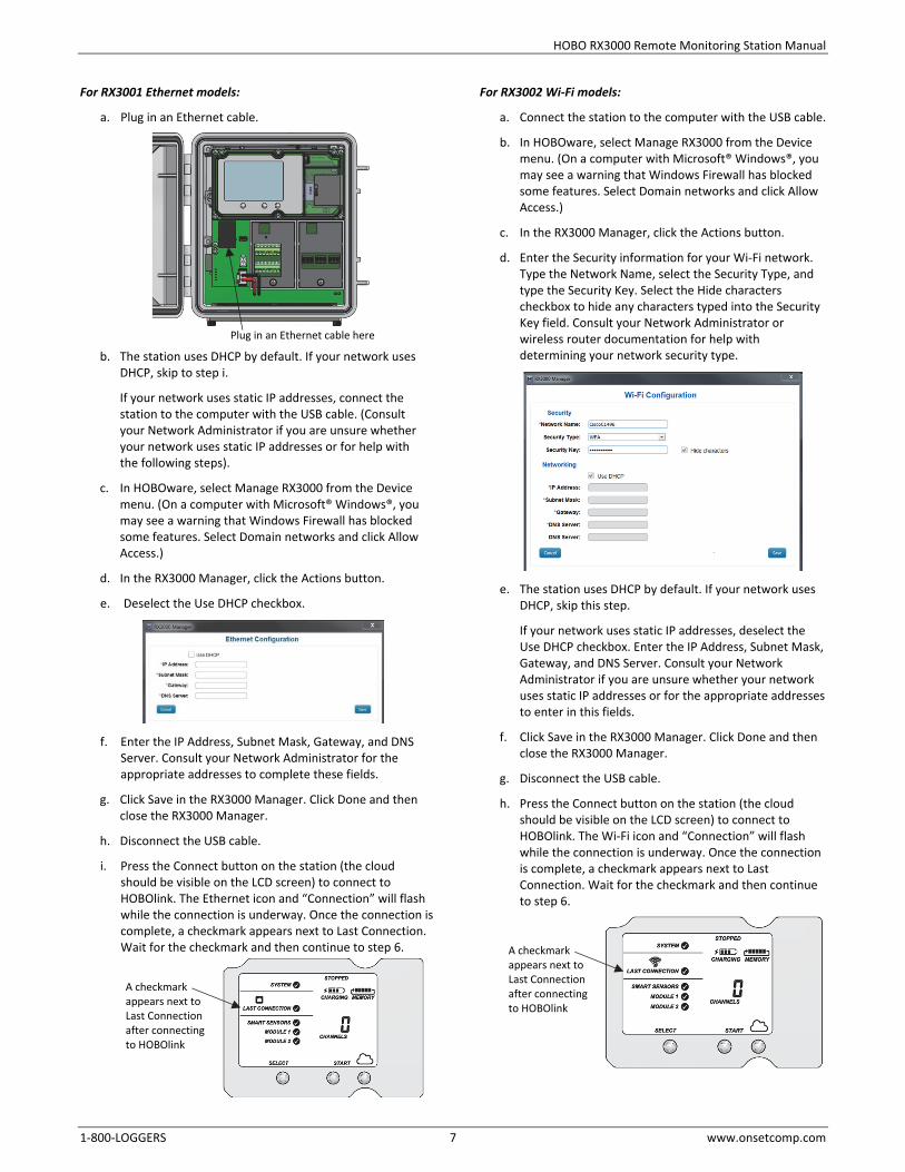
For RX3001 Ethernet models:
a. Plug in an Ethernet cable.
b. The station uses DHCP by default. If your network uses DHCP, skip to step i.
If your network uses static IP addresses, connect the station to the computer with the USB cable. (Consult your Network Administrator if you are unsure whether your network uses static IP addresses or for help with the following steps).
c. In HOBOware, select Manage RX3000 from the Device menu. (On a computer with Microsoft® Windows®, you may see a warning that Windows Firewall has blocked some features. Select Domain networks and click Allow Access.)
d. In the RX3000 Manager, click the Actions button.
e. Deselect the Use DHCP checkbox.
f. Enter the IP Address, Subnet Mask, Gateway, and DNS Server. Consult your Network Administrator for the appropriate addresses to complete these fields.
g. Click Save in the RX3000 Manager. Click Done and then close the RX3000 Manager.
h. Disconnect the USB cable.
i. Press the Connect button on the station (the cloud should be visible on the LCD screen) to connect to HOBOlink. The Ethernet icon and “Connection” will flash while the connection is underway. Once the connection is complete, a checkmark appears next to Last Connection. Wait for the checkmark and then continue to step 6.
For RX3002 Wi-Fi models:
a. Connect the station to the computer with the USB cable.
b. In HOBOware, select Manage RX3000 from the Device menu. (On a computer with Microsoft® Windows®, you may see a warning that Windows Firewall has blocked some features. Select Domain networks and click Allow Access.)
c. In the RX3000 Manager, click the Actions button.
d. Enter the Security information for your Wi-Fi network. Type the Network Name, select the Security Type, and type the Security Key. Select the Hide characters checkbox to hide any characters typed into the Security Key field. Consult your Network Administrator or wireless router documentation for help with determining your network security type.
e. The station uses DHCP by default. If your network uses DHCP, skip this step.
If your network uses static IP addresses, deselect the Use DHCP checkbox. Enter the IP Address, Subnet Mask, Gateway, and DNS Server. Consult your Network Administrator if you are unsure whether your network uses static IP addresses or for the appropriate addresses to enter in this fields.
f. Click Save in the RX3000 Manager. Click Done and then close the RX3000 Manager.
g. Disconnect the USB cable.
h. Press the Connect button on the station (the cloud should be visible on the LCD screen) to connect to HOBOlink. The Wi-Fi icon and “Connection” will flash while the connection is underway. Once the connection is complete, a checkmark appears next to Last Connection. Wait for the checkmark and then continue to step 6.
Plug in an Ethernet cable here
A checkmark appears next to Last Connection after connecting to HOBOlink
A checkmark appears next to Last Connection after connecting to HOBOlink

HOBO RX3000 Remote Monitoring Station Manual
1-800-LOGGERS 8 www.onsetcomp.com
6. Plug in and search for smart sensors. a. Feed the smart sensor cable for one smart sensor
through the larger of the two cable openings and plug it into one of the 10 smart sensor connectors. Repeat for any additional smart sensors.
b. Press the Select button to view the smart sensors on the LCD and then press the Search button (the magnifying glass icon should be visible as in the example below). The station will search for all connected smart sensors and show the number of channels after a few seconds.
Note that some smart sensors have more than one channel associated with them so the number of channels may not match the physical number of smart sensors connected (for example the temperature/RH smart sensor has two channels: one for temperature and one for RH).
7. Connect analog sensors or relay devices. If you are using the optional analog sensor module or relay module, follow the steps in this section to connect the sensors or devices. Be sure to feed any cables or wires through the smaller cable access opening shown below.
Important: If you will be installing the weatherproof rubber cable channel in the cable access opening as described in Deploying and Mounting the Station, the cable diameter for analog sensors or relay devices must be 4.0 mm (0.156 in.) to fit through one of the five smaller holes or 6.4 mm (0.25 in.) to fit through one of the five larger holes. If the cable diameter is too small, build up the diameter using heat shrink. If the cable is too big, splice on another cable with a smaller diameter to fit through the hole.
To connect analog sensors: You can connect a two- or three-wire sensor or transducer to one of the four terminals in the analog module. a. Loosen the screw for each pin on the screw terminal. b. Feed the wire through the smaller of the two cable
access openings. c. Insert the appropriate wire into the screw terminal (see
the pinout table below). The wire should be trimmed to expose 0.25 inches ±0.04 inches of bare wire.
d. Tighten the screw.
Analog Module Pinout Table J1 Pin # Pin Description
J2 Pin # Pin Description
1 CH1 SIGNAL 1 CH3 SIGNAL
2 CH1 GND 2 CH3 GND
3 +12V Excitation 3 +12V Excitation
4 GND (EX. RTN) 4 GND (EX. RTN)
5 CH2 SIGNAL 5 CH4 SIGNAL
6 CH2 GND 6 CH4 GND
7 SHIELD 7 SHIELD
Note: All four input channels share the same common ground.
Analog Module Functional Diagram
To connect relay devices:
You can connect up to three devices to the relay module. The relays are only for low power switching. To switch to higher power, use an appropriately rated relay and use the station relay to switch the external relay on or off. a. Loosen the screw for each pin on the screw terminal. b. Feed the wire through the smaller of the two cable
access openings. c. Insert the appropriate wire into the screw terminal (pins
1 and 2 are interchangeable, pin 3 is optional; see the pinout table).
d. Tighten the screw.
Plug in smart sensors here
Press the Select button to view the smart sensor screen
Press the Search button for the stationto find all connected smart sensors
Feed analog sensor and relay cables through this opening to connect them to the optional modules
HOBO RX3000 Remote Monitoring Station Manual
1-800-LOGGERS 9 www.onsetcomp.com
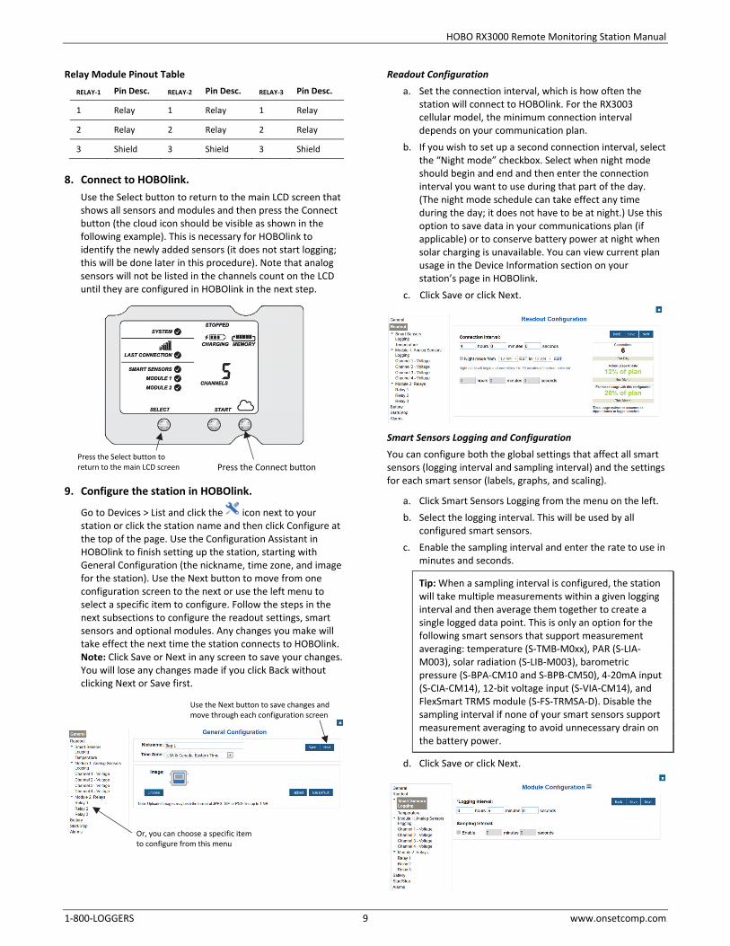
Relay Module Pinout Table RELAY-1 Pin Desc. RELAY-2 Pin Desc. RELAY-3 Pin Desc.
1 Relay 1 Relay 1 Relay
2 Relay 2 Relay 2 Relay
3 Shield 3 Shield 3 Shield
8. Connect to HOBOlink.
Use the Select button to return to the main LCD screen that shows all sensors and modules and then press the Connect button (the cloud icon should be visible as shown in the following example). This is necessary for HOBOlink to identify the newly added sensors (it does not start logging; this will be done later in this procedure). Note that analog sensors will not be listed in the channels count on the LCD until they are configured in HOBOlink in the next step.
9. Configure the station in HOBOlink.
Go to Devices > List and click the icon next to your station or click the station name and then click Configure at the top of the page. Use the Configuration Assistant in HOBOlink to finish setting up the station, starting with General Configuration (the nickname, time zone, and image for the station). Use the Next button to move from one configuration screen to the next or use the left menu to select a specific item to configure. Follow the steps in the next subsections to configure the readout settings, smart sensors and optional modules. Any changes you make will take effect the next time the station connects to HOBOlink. Note: Click Save or Next in any screen to save your changes. You will lose any changes made if you click Back without clicking Next or Save first.
Readout Configuration a. Set the connection interval, which is how often the
station will connect to HOBOlink. For the RX3003 cellular model, the minimum connection interval depends on your communication plan.
b. If you wish to set up a second connection interval, select the “Night mode” checkbox. Select when night mode should begin and end and then enter the connection interval you want to use during that part of the day. (The night mode schedule can take effect any time during the day; it does not have to be at night.) Use this option to save data in your communications plan (if applicable) or to conserve battery power at night when solar charging is unavailable. You can view current plan usage in the Device Information section on your station’s page in HOBOlink.
c. Click Save or click Next.
Smart Sensors Logging and Configuration You can configure both the global settings that affect all smart sensors (logging interval and sampling interval) and the settings for each smart sensor (labels, graphs, and scaling).
a. Click Smart Sensors Logging from the menu on the left. b. Select the logging interval. This will be used by all
configured smart sensors. c. Enable the sampling interval and enter the rate to use in
minutes and seconds.
Tip: When a sampling interval is configured, the station will take multiple measurements within a given logging interval and then average them together to create a single logged data point. This is only an option for the following smart sensors that support measurement averaging: temperature (S-TMB-M0xx), PAR (S-LIA-M003), solar radiation (S-LIB-M003), barometric pressure (S-BPA-CM10 and S-BPB-CM50), 4-20mA input (S-CIA-CM14), 12-bit voltage input (S-VIA-CM14), and FlexSmart TRMS module (S-FS-TRMSA-D). Disable the sampling interval if none of your smart sensors support measurement averaging to avoid unnecessary drain on the battery power.
d. Click Save or click Next.
Or, you can choose a specific item to configure from this menu
Press the Connect buttonPress the Select button to return to the main LCD screen
Use the Next button to save changes and move through each configuration screen
HOBO RX3000 Remote Monitoring Station Manual
1-800-LOGGERS 10 www.onsetcomp.com
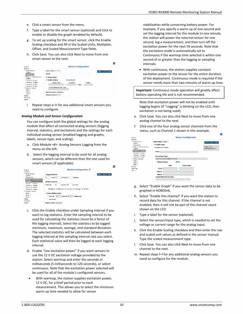
e. Click a smart sensor from the menu. f. Type a label for the smart sensor (optional) and click to
enable or disable the graph (enabled by default). g. To set up scaling for the smart sensor, click the Enable
Scaling checkbox and fill in the Scaled Units, Multiplier, Offset, and Scaled Measurement Type fields.
h. Click Save. You can also click Next to move from one smart sensor to the next.
i. Repeat steps e–h for any additional smart sensors you
need to configure.
Analog Module and Sensor Configuration You can configure both the global settings for the analog module that affect all connected analog sensors (logging interval, statistics, and excitation) and the settings for each individual analog sensor (enabled logging and graphs, labels, sensor type, and scaling). a. Click Module <#>: Analog Sensors Logging from the
menu on the left. b. Select the logging interval to be used for all analog
sensors, which can be different than the one used for smart sensors (if applicable).
c. Click the Enable checkbox under Sampling Interval if you want to log statistics. Enter the sampling interval to be used for calculating the statistics (must be a factor of the logging interval). Select the statistics to be logged: minimum, maximum, average, and standard deviation. The selected statistics will be calculated between each logging interval at the sampling interval rate you select. Each statistical value will then be logged at each logging interval.
d. Enable “Use excitation power” if you want sensors to use the 12 V DC excitation voltage provided by the station. Select warmup and enter the seconds or milliseconds (5 milliseconds to 120 seconds), or select continuous. Note that the excitation power selected will be used for all of the module’s configured sensors.
• With warmup, the station supplies excitation power, 12 V DC, for a brief period prior to each measurement. This allows you to select the minimum warm-up time needed to allow for sensor
stabilization while conserving battery power. For example, if you specify a warm-up of one second and set the logging interval for the module to one minute, the station will power the external sensor for one second, log a measurement, and then turn off the excitation power for the next 59 seconds. Note that the excitation mode is automatically set to Continuous if the warmup time selected is within one second of or greater than the logging or sampling intervals.
• With continuous, the station supplies constant excitation power to the sensor for the entire duration of the deployment. Continuous mode is required if the sensor needs more than two minutes of warm-up time.
Important: Continuous mode operation will greatly affect battery operating life and is not recommended.
Note that excitation power will not be enabled until logging begins (if “Logging” is blinking on the LCD, then excitation is not being used).
e. Click Save. You can also click Next to move from one analog channel to the next.
f. Click one of the four analog sensor channels from the menu, such as Channel 1 shown in this example.
g. Select “Enable Graph” if you want the sensor data to be
graphed in HOBOlink. h. Select “Enable this channel” if you want the station to
record data for this channel. If the channel is not enabled, then it will not be part of the channel count shown on the LCD.
i. Type a label for the sensor (optional). j. Select the sensor/input type, which is needed to set the
voltage or current range for the analog input. k. Click the Enable Scaling checkbox and then enter the raw
and scaled unit values as defined in the sensor manual. Type the scaled measurement type.
l. Click Save. You can also click Next to move from one channel to the next.
m. Repeat steps f–l for any additional analog sensors you need to configure for the module.

HOBO RX3000 Remote Monitoring Station Manual
1-800-LOGGERS 11 www.onsetcomp.com
Relay Module Configuration a. Click one of the three relays from the menu on the left,
such as Relay 1 in the following example.
b. Type a label and select Open or Closed for the Normal
Relay State. The label can be used to show what Open or Closed corresponds to in your system (for example, “closed relay turns pump on”).
c. Select what should happen on the next connection with the station: open relay, close relay, or leave it at its current state.
d. Click Save or click Next. e. Repeat steps a–d for any additional relays you wish to
configure.
Tip: Refer to Setting System and Sensor Alarms for details on using sensor alarms to activate the relays.
10. Start logging. After you have finished configuring all the settings in HOBOlink, you can start logging when ready. Press the Start button on the station to start logging. The station will connect to HOBOlink (“Connection” will blink on the LCD) and then logging will begin at the logging interval specified for smart sensors and analog sensors (if applicable).
You can also start logging from HOBOlink. Select Start/Stop from the Configure menu in HOBOlink and click Start. Logging will not begin until the next time the station connects to HOBOlink. Press the Connect button on the station to connect to HOBOlink at any time.
Once logging begins, “Logging” appears in the upper right corner of the LCD as shown in the following example. “Logging” will blink until the first logging sample is recorded. At that point, it will stop blinking and remain illuminated until logging is stopped. Also note that the channels count on the LCD screen will be updated to include any analog sensors that were enabled in HOBOlink.
Important: See Deploying and Mounting the Station for installation steps and other deployment guidelines. If using the station outdoors or in harsh indoor conditions, you must install the sensor cable channels and the plates for weatherproofing.
Viewing Data in HOBOlink Data is uploaded to HOBOlink each time the device connects. For a snapshot of the latest conditions, go to your station’s page to view the readings from the last connection for smart sensors and logged analog sensors. You can also view any enabled graphs as shown in the following example.
Logged data is saved in a database. You can export this data on demand as needed or set up automatic exports that are delivered to email and/or FTP addresses on a schedule you specify. To download and export data: 1. In HOBOlink, click Data and select Custom Data. 2. Click Create Export Settings. 3. Follow the instructions on the screen to select the name,
format, time zone, and time frame, and then the devices and sensors to include in the export. Reorder the sensors as needed.
4. Click Save to keep these settings for future use or click Export Data to export immediately.
To set up a scheduled data delivery: 1. From the Custom Data tab, select Schedule Delivery (or click
Data and then select Data Delivery). 2. Click New. 3. Enable the Active checkbox.
Press this button to start logging
“Logging” appears when logging begins
Channel count updated for any enabled analog sensors
HOBO RX3000 Remote Monitoring Station Manual
1-800-LOGGERS 12 www.onsetcomp.com
4. Under General Settings, type the name of the delivery schedule and the frequency of delivery. Select other settings if desired.
5. Under Select Data to Export, choose the name of the custom data export you want to be delivered (or follow the previous set of steps to set up a custom data export).
6. Under Data Destination, select FTP or Email for the delivery method and fill in the appropriate fields.
7. Click Save. Data will then be delivered on the schedule you selected.
For more information on Data Delivery, see the HOBOlink Help.
Setting System and Sensor Alarms You can set up both system and sensor alarms in HOBOlink. System alarms can trip when there is a missed connection, the battery is low, or if there is a smart sensor failure. With a sensor alarm, you can configure an alarm to trip at one level and clear at another.
System Alarms To add a system alarm:
1. In HOBOlink, click the arrow next to on the Devices page or next to Configure button at the top of your station’s page and select Alarm Configuration.
2. Click the Edit System Alarms link. 3. For Missed Connection alarms:
a. Under Communication, select the Missed Connection checkbox.
b. Set the length of time for HOBOlink to wait after a missed connection before the alarm trips.
c. Select the action to be taken when this alarm trips: send an email or text. Enter the details and then select “Send on Clear Also” if you want an email or text when the alarm clears as well.
Important: Standard data fees and text messaging rates may apply when using text notifications. Onset does not charge a fee or guarantee delivery of text alerts, which is subject to your carrier’s service and location. See the HOBOlink Help for additional details on alarm notifications.
d. Click Add Action if you want multiple actions to be taken when the alarm trips (for example send an email and a text).
4. For Battery Low and Sensor Failure alarms: a. Under Device, select the Battery Low and/or Sensor
Failure checkboxes. b. Select how you want to be notified when these alarms
trip: by email or text. Enter the appropriate addresses and then select “Send on Clear Also” if you want an email or text when these alarms clear as well.
5. Click Add Action if you want multiple actions to be taken when the alarm trips (for example send an email and a text).
6. Click Save. Changes will take effect the next time the station connects to HOBOlink.
Red alarm symbols will appear in HOBOlink when these alarms trip (if enabled).
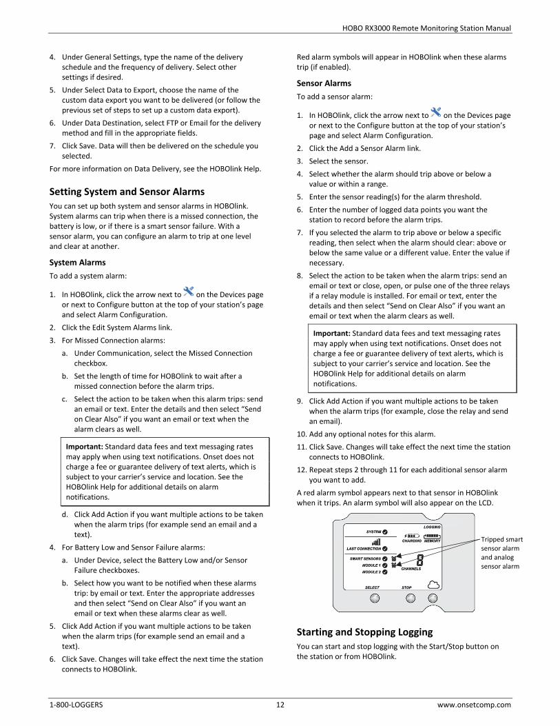
Sensor Alarms To add a sensor alarm:
1. In HOBOlink, click the arrow next to on the Devices page or next to the Configure button at the top of your station’s page and select Alarm Configuration.
2. Click the Add a Sensor Alarm link. 3. Select the sensor. 4. Select whether the alarm should trip above or below a
value or within a range. 5. Enter the sensor reading(s) for the alarm threshold. 6. Enter the number of logged data points you want the
station to record before the alarm trips. 7. If you selected the alarm to trip above or below a specific
reading, then select when the alarm should clear: above or below the same value or a different value. Enter the value if necessary.
8. Select the action to be taken when the alarm trips: send an email or text or close, open, or pulse one of the three relays if a relay module is installed. For email or text, enter the details and then select “Send on Clear Also” if you want an email or text when the alarm clears as well.
Important: Standard data fees and text messaging rates may apply when using text notifications. Onset does not charge a fee or guarantee delivery of text alerts, which is subject to your carrier’s service and location. See the HOBOlink Help for additional details on alarm notifications.
9. Click Add Action if you want multiple actions to be taken when the alarm trips (for example, close the relay and send an email).
10. Add any optional notes for this alarm. 11. Click Save. Changes will take effect the next time the station
connects to HOBOlink. 12. Repeat steps 2 through 11 for each additional sensor alarm
you want to add. A red alarm symbol appears next to that sensor in HOBOlink when it trips. An alarm symbol will also appear on the LCD.
Starting and Stopping Logging You can start and stop logging with the Start/Stop button on the station or from HOBOlink.
Tripped smart sensor alarm and analog sensor alarm

HOBO RX3000 Remote Monitoring Station Manual
1-800-LOGGERS 13 www.onsetcomp.com
To start and stop logging with the station: 1. When the station is stopped, press the Start button to start
logging. The device will connect to HOBOlink (“Connection” will blink on the LCD) and then logging will begin at the logging interval specified for smart sensors and analog sensors (if applicable).
2. To stop logging, press the Stop button. Logging stops immediately. Note that the station will continue to connect to HOBOlink even if it is not logging.
To start and stop the station from HOBOlink:
1. Click the arrow next to on the Devices page or next to Configure button at the top of your station’s page and select Start/Stop.
2. Click Start or Stop in the Logging Configuration panel. The station will start or stop logging the next time it connects to HOBOlink.
Adding or Removing Smart Sensors To add or remove smart sensors from the station: 1. If the station is currently logging, press the Stop button to
stop it. 2. Press the Connect button and wait for the station to
connect to HOBOlink so that all the latest data is offloaded before changing smart sensors.
3. If using the rubber cable channel, unscrew the plates and push the cable channel out of the case. Open it to access any smart sensors.
4. Unplug any smart sensors you wish to remove. Plug in any new smart sensors.
5. Press the Select button to view the smart sensors on the LCD screen.
6. Press the Search button for the station to detect all the smart sensors currently connected.
7. Press the Start button to begin logging again. The station will automatically connect to HOBOlink.
8. If using the rubber cable channel, grease and place any smart sensor cables or plugs, reinsert the rubber cable channel, and reinstall the plates. See Installing the Weatherproof Rubber Cable Channel and Covers for details.
9. Make any configuration changes in HOBOlink as desired, such as adding sensor labels or scaling (see Setting up the Station).
Note that any existing alarms associated with removed sensors will still be listed in HOBOlink. See the HOBOlink Help for details on deleting alarms. Also, if you are using alarms to activate relays, check that the relays are in the proper state.
Adding or Removing Modules The RX3000 has two slots in which optional analog and relay modules can be installed. You can add or remove these modules as desired. To add a module: 1. Stop the station if it is currently logging. 2. Press the Connect button and wait for the station to
connect to HOBOlink so that all the latest data is offloaded before adding a new module.
3. Power down the station (disconnect the battery and unplug any charging device).
4. Insert the module into the left or right module slot. 5. Using a Phillips-head screwdriver, tighten the screw at the
bottom of the module. 6. Plug in the battery and charging device, and wait for the
device to power up. Verify that the new module is listed on the LCD screen with a checkmark.
7. The station should automatically connect to HOBOlink (press the Connect button on the station if needed). Check your station’s page to make sure the new module is listed.
8. Connect any analog sensors or relays (see step 7 in Setting up the Station for details). Make any configuration changes as needed in HOBOlink and start logging again when ready.
WARNING: If you inadvertently install modules while the power is on, you must disconnect and then reconnect the battery and charging device to guarantee proper operation.
To remove a module: 1. Stop the station if it is currently logging. 2. Press the Connect button and wait for the station to
connect to HOBOlink so that all the latest data is offloaded before adding a new module.
3. Power down the station (disconnect the battery and unplug any charging device).
4. Disconnect any analog sensors or relay devices. 5. Using a Phillips-head screwdriver, unscrew the bottom
screw on the module until loosened (it will remain attached to the module).
6. With your fingers on the top and bottom edges of the module, carefully pull it out of the slot.
Press this button to start logging
Press this button to stop logging
The station is logging
The station is stopped
HOBO RX3000 Remote Monitoring Station Manual
1-800-LOGGERS 14 www.onsetcomp.com
7. Plug in the battery and charging device. Make sure the station connects to HOBOlink (press the Connect button on the station if needed).
8. Make any configuration changes as needed in HOBOlink and start logging again when ready.
WARNING: If you inadvertently remove modules while the power is on, you must disconnect and then reconnect the battery and charging device to guarantee proper operation.
Note that any existing alarms associated with removed modules will be listed in HOBOlink. See the HOBOlink Help for details on deleting alarms. Also, if you are using alarms to activate relays, check that the relays are in the proper state.
Managing Connections to HOBOlink The station will connect to HOBOlink on the connection interval you selected in Readout Configuration. To change the connection schedule:
1. Click the arrow next to on the Devices page or next to Configure button at the top of your station’s page and select Readout Configuration.
2. Set the connection interval. For the RX3003 cellular model, the minimum connection interval depends on your communication plan.
3. If you wish to set up a second connection interval, select the “Night Mode” checkbox. Select when night mode should begin and end and then enter the connection interval you want to use during that part of the day.
4. Click Save. The changes to the connection interval will take place the next time the station connects to HOBOlink.
You can also connect to HOBOlink from the station at any time, regardless of the connection schedule. Press the Connect button on the station to connect to HOBOlink. Unless the station is running on a night mode connection interval, the normal connection schedule will then restart after the connection is complete. For example, a station is configured to connect hourly and the last connection on its regular schedule occurred at 10:05. If you use the Connect button on the station to connect to HOBOlink at 10:15, the next connection will then be about 11:15 based on the one-hour connection interval. Similarly, if a station misses a connection, the connection schedule will shift depending on the time of the next successful connection. While the station is using a second, night mode schedule, all connections will follow that schedule only; any extra connections while the station is in night mode will not cause a shift in the connection schedule. Also note that the station will connect to HOBOlink when the device is powered up and when you press the Start button. For RX3003 cellular models: All connections to HOBOlink count toward your communications plan. If the station is nearing its limit for monthly cell use, minimize unscheduled connections. This includes any connections for alarms or changes you make to the connection schedule. You can also increase the connection interval to reduce the number of connections to HOBOlink per day. Check the Device Information section on your station page in HOBOlink to check the status of the monthly communications plan usage for the station.
Checking Latest Conditions with HOBOware The RX3000 Manager within HOBOware and HOBOware Pro is available for showing the current sensor readings in an RX3000 Station connected to a computer. To do this:
1. Connect the station to the computer with a USB cable and open HOBOware.
2. From the Device menu in HOBOware, select Manage RX3000. Note for Windows: You may see a warning that Windows Firewall has blocked some features. Select Domain networks and click Allow Access.
3. In the RX3000 Manager, the Latest Conditions panel shows the currently configured sensors and modules for the
device. Click the refresh button in the Latest Conditions panel to take a measurement for each sensor and display the value. (Note: Sensor readings do not refresh automatically.) You can also view general information about the RX3000 Station in the Device information panel.
4. Close the RX3000 Manager when done and disconnect the USB cable.
Note: The Latest Conditions and Device Information available in the RX3000 Manager are for reference only. Use HOBOlink to view complete station details, access logged data, and configure the device.
Deploying and Mounting the Station Follow the guidelines and steps in this section for deploying and mounting the station.
Deployment Guidelines When deploying the station:
• Check the signal strength on the LCD in the location you wish to deploy the station to make sure it will be able to reliably connect to HOBOlink (RX3002 Wi-Fi and RX3003 cellular models). The station may have difficulty connecting if there is only one bar illuminated in the Wi-Fi or cellular LCD symbol. (The signal strength shown on the LCD is from the last connection.)
• The RX3003 cellular model must be mounted at least one foot from all sensors to avoid interference from the built-in radio module and antenna with the measurements made by the sensors.
• Make sure the station remains in a vertical position once it is placed in its deployment location. If it is mounted horizontally, the battery could be damaged over time as it is charged and the antenna (if applicable) will not have optimal range.
• If you haven’t already done so, plug in an AC adapter, solar panel, or other external power source to keep the battery charged.
• If you are using a wind speed/direction sensor or if the station will be installed on a roof or in a location with exposure to lightning, use the grounding wire included with this station and ground the tripod or mast using appropriate grounding, such as the Grounding Kit (M-GKA). A grounding wire may also reduce potential sensor errors that can result from installing near other radio or

HOBO RX3000 Remote Monitoring Station Manual
1-800-LOGGERS 15 www.onsetcomp.com
electrical equipment or antennas. See Installing the Grounding Wire.
• Make sure all cables and wires are fastened securely, routed through the cable access openings, and placed in the rubber cable channels. Any empty holes in the cable channels need to be filled with the appropriate size plug to ensure the station is weatherproof. See Installing the Weatherproof Rubber Cable Channel and Covers.
• Do not store excess sensor cable wire coiled inside the station case or within one foot outside the case.
• Protect cables and wires with conduit. Exposed cables can be chewed by rodents.
• Make sure the total cable length for all installed smart sensors does not exceed 100 m (328 ft).
• Consider using a padlock to restrict access to the station. With the station door closed, hook a padlock through one of the latches on the right side of the door and lock it.
Installing the Grounding Wire Insert the grounding wire through the larger of the two cable access openings and plug it into the ground connector. You may need pliers to connect it to the station. The grounding wire must be connected to a properly grounded mast (typically on one side of the U-bolt) when the station is mounted.
Mounting the Station Attach the mounting plates with a Phillips-head screwdriver to the back of the station to mount it on a flat surface. Mount the station vertically to a wall or board using screws.
You can also mount the station vertically to a mast or pole and tripod using U-bolts (unscrew the nut on the U-bolt to place around the mast or pole). Screw the mounting plates to the back of the station as shown above. Make sure the mounting
plates are mounted against the flat part of the U-bolt saddle clamps. If using the grounding wire, attach it to one end of the U-bolt. Refer to the Tripod Setup Guide for full details.
Installing the Weatherproof Rubber Cable Channel and Covers
Important: This is required for outdoor and weatherproof deployments and recommended for harsh indoor environments where debris could enter the station.
1. Make sure all sensors and cables are installed, including the solar panel, AC adapter cable, or external DC power cable, and the grounding wire.
2. Grease one of the two rubber cable channels. a. Apply a small amount of silicone grease (about the size
of a pea) onto your fingertip. b. Lightly coat all four outer edges on the rubber cable
channel with grease. c. Open the cable channel and lightly coat the inside of
both halves (the part with the grooves). 3. Lightly coat each cable with grease. 4. Place the greased cables in the channel grooves.
a. Open the greased rubber cable channel so that the channel’s hinged side is oriented to the left.
b. Place each cable or wire into a single groove in the cable channel, installing them from left to right.
• For the large cable channel, place smart sensor cables in the grooves. If using the grounding wire, place the black portion of it into the rightmost hole in the cable channel (the hole farthest from the hinged side).
• For the small cable channel, place the AC adapter or solar panel cable and any analog sensor cables or relay wires in each of the grooves. Place larger cables in the five grooves on the left closest to the hinged side and smaller cables in the five grooves on the right.
Connect the grounding wire here
Cables placed in grooves of rubber cable channel
Screw the mounting plates to the back of station
Use the holes on the mounting plates to affix the station to a board or flat surface
Attach the station to a pole or mast with U-bolts

HOBO RX3000 Remote Monitoring Station Manual
1-800-LOGGERS 16 www.onsetcomp.com
Important: The cable diameter must be 4.0 mm (0.156 in.) to fit through one of the five smaller holes or 6.4 mm (0.25 in.) to fit through one of the five larger holes in the rubber cable channel. If the cable diameter is too small, build up the diameter using heat shrink. If the cable is too big, splice on another cable with a smaller diameter to fit through the hole.
5. Close the rubber cable channel making sure the cables and wires remain in their grooves.
6. Press the cable channel into the opening until it is flush with the outside of the case (when fully seated, the channel will project slightly into the inside of the case). To reduce the amount of excess cable in the case, gently pull the cables toward you as you press the channel into place.
7. Using thumbscrews, install the plate on the cable access opening to hold the rubber cable channel in place. (Use the smaller plate for the top opening and the larger plate for the larger opening.) Do not fully tighten the thumbscrews yet; keep them loosely installed while you install the rubber plugs in the next step.
8. Lightly coat rubber plugs with a small amount of grease and use the plugs to fill any empty holes in the two cable channels. There are large and small plugs; use the large plugs in the larger holes and the small plugs in the smaller holes. Insert the thin part of the plug into the hole and push it in until the thick part of the plug fills the hole.
9. Repeat steps 2 through 8 with the other rubber cable channel.
10. Use the included wrench to tighten the four thumb screws on each of the two plates until the plates are flat against the case.
Care and Maintenance The station is designed for outdoor use, but should be inspected periodically. When inspecting the station, do the following:
• Verify the station enclosure is free of visible damage or cracks.
• Make sure the station enclosure is clean. Wipe any dust or grime off with a damp cloth.
• Wipe any water off the station before opening it.
• Check that all cables and wires are free of damage, such as cracks, cuts, and splits.
• Make sure cables and wires are still fastened securely and any conduit is still intact.
• Verify that all cables and wires are free of corrosion. If moisture is visible inside the station or if there is any sign of corrosion on the connectors, spray WD-40® or an equivalent electronics-safe corrosion inhibitor on the connectors. This will displace moisture and prevent additional corrosion. Be sure to determine the source of the moisture and fix it. Check the cable channel and cover seals for any sign of moisture entry.
Troubleshooting Error codes can appear on the LCD if a problem arises with the station or a sensor. This table describes common error codes that may appear. Contact Onset Technical Support for help.
Fault Code # Description Action to Take
001 System Failed Initialization
Power cycle the station (disconnect the battery and charging device, wait for a minute, and then plug the battery and charging device back in).
004 Sensor Error/Fault
Check the smart sensor data in HOBOlink to see which smart sensor is producing an error. You may need to remove or replace the smart sensor if the smart sensor is consistently reporting erroneous data.
036 Missing Module
A previously installed module has gone missing. Power cycle the station (disconnect the battery and charging device, wait for a minute, and then plug the battery and charging device back in).
037 Module Improperly Installed
The station must be powered off when installing a module to guarantee proper operation. Power cycle the station (disconnect the battery and charging device, wait for a minute, and then plug the battery and charging device back in).
129 Smart Sensor Bus Fault
There is a problem with one or more of the smart sensor connections. Check that all smart sensors are fully plugged in (follow the instructions in Adding or Removing Smart Sensors). Also check that the smart sensor cables are ok.
132 Analog Excitation Bus Fault
Check the analog sensor connection and the excitation settings for the sensor in HOBOlink.
Both cable channels installed with plugs
Channel in place with plate (thumbscrews not tightened); fill holes with plugs Insert thin end of
plug into hole in cable channel
HOBO RX3000 Remote Monitoring Station Manual
1-800-LOGGERS 17 www.onsetcomp.com
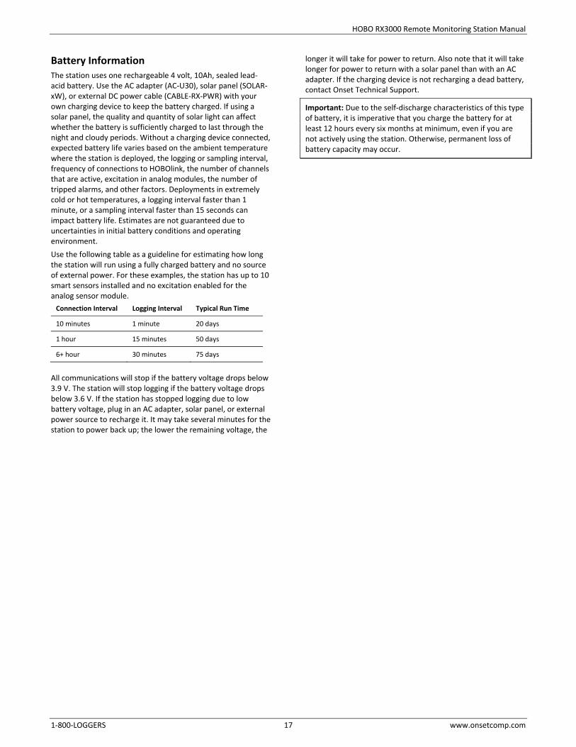
Battery Information The station uses one rechargeable 4 volt, 10Ah, sealed lead-acid battery. Use the AC adapter (AC-U30), solar panel (SOLAR-xW), or external DC power cable (CABLE-RX-PWR) with your own charging device to keep the battery charged. If using a solar panel, the quality and quantity of solar light can affect whether the battery is sufficiently charged to last through the night and cloudy periods. Without a charging device connected, expected battery life varies based on the ambient temperature where the station is deployed, the logging or sampling interval, frequency of connections to HOBOlink, the number of channels that are active, excitation in analog modules, the number of tripped alarms, and other factors. Deployments in extremely cold or hot temperatures, a logging interval faster than 1 minute, or a sampling interval faster than 15 seconds can impact battery life. Estimates are not guaranteed due to uncertainties in initial battery conditions and operating environment. Use the following table as a guideline for estimating how long the station will run using a fully charged battery and no source of external power. For these examples, the station has up to 10 smart sensors installed and no excitation enabled for the analog sensor module.
Connection Interval Logging Interval Typical Run Time
10 minutes 1 minute 20 days
1 hour 15 minutes 50 days
6+ hour 30 minutes 75 days
All communications will stop if the battery voltage drops below 3.9 V. The station will stop logging if the battery voltage drops below 3.6 V. If the station has stopped logging due to low battery voltage, plug in an AC adapter, solar panel, or external power source to recharge it. It may take several minutes for the station to power back up; the lower the remaining voltage, the
longer it will take for power to return. Also note that it will take longer for power to return with a solar panel than with an AC adapter. If the charging device is not recharging a dead battery, contact Onset Technical Support.
Important: Due to the self-discharge characteristics of this type of battery, it is imperative that you charge the battery for at least 12 hours every six months at minimum, even if you are not actively using the station. Otherwise, permanent loss of battery capacity may occur.
1-800-LOGGERS (564-4377) • 508-759-9500 www.onsetcomp.com/support/contact
© 2015–2017 Onset Computer Corporation. All rights reserved. Onset, HOBO, and HOBOlink are trademarks or registered trademarks of Onset Computer Corporation. All other trademarks are the property of their respective companies.
18255-I
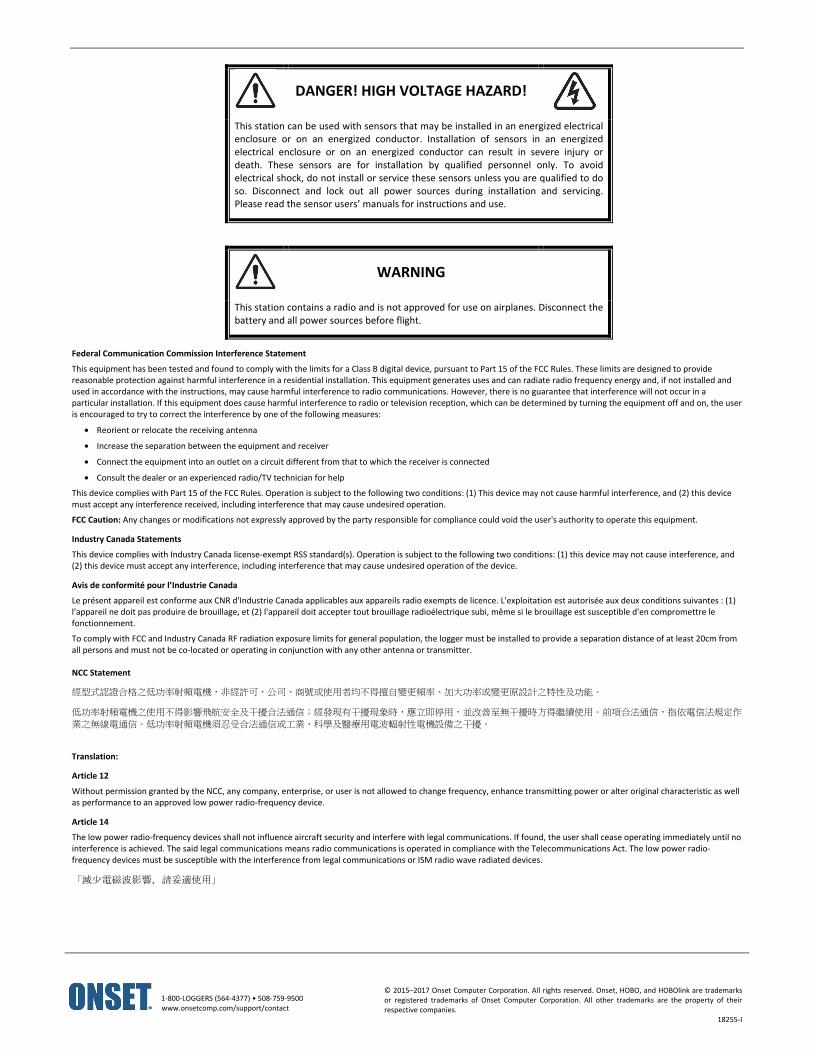
DANGER! HIGH VOLTAGE HAZARD!
This station can be used with sensors that may be installed in an energized electrical enclosure or on an energized conductor. Installation of sensors in an energized electrical enclosure or on an energized conductor can result in severe injury or death. These sensors are for installation by qualified personnel only. To avoid electrical shock, do not install or service these sensors unless you are qualified to do so. Disconnect and lock out all power sources during installation and servicing. Please read the sensor users’ manuals for instructions and use.
WARNING
This station contains a radio and is not approved for use on airplanes. Disconnect the battery and all power sources before flight.
Federal Communication Commission Interference Statement
This equipment has been tested and found to comply with the limits for a Class B digital device, pursuant to Part 15 of the FCC Rules. These limits are designed to provide reasonable protection against harmful interference in a residential installation. This equipment generates uses and can radiate radio frequency energy and, if not installed and used in accordance with the instructions, may cause harmful interference to radio communications. However, there is no guarantee that interference will not occur in a particular installation. If this equipment does cause harmful interference to radio or television reception, which can be determined by turning the equipment off and on, the user is encouraged to try to correct the interference by one of the following measures:
• Reorient or relocate the receiving antenna
• Increase the separation between the equipment and receiver
• Connect the equipment into an outlet on a circuit different from that to which the receiver is connected
• Consult the dealer or an experienced radio/TV technician for help
This device complies with Part 15 of the FCC Rules. Operation is subject to the following two conditions: (1) This device may not cause harmful interference, and (2) this device must accept any interference received, including interference that may cause undesired operation.
FCC Caution: Any changes or modifications not expressly approved by the party responsible for compliance could void the user's authority to operate this equipment.
Industry Canada Statements
This device complies with Industry Canada license-exempt RSS standard(s). Operation is subject to the following two conditions: (1) this device may not cause interference, and (2) this device must accept any interference, including interference that may cause undesired operation of the device.
Avis de conformité pour l’Industrie Canada
Le présent appareil est conforme aux CNR d'Industrie Canada applicables aux appareils radio exempts de licence. L'exploitation est autorisée aux deux conditions suivantes : (1) l'appareil ne doit pas produire de brouillage, et (2) l'appareil doit accepter tout brouillage radioélectrique subi, même si le brouillage est susceptible d'en compromettre le fonctionnement.
To comply with FCC and Industry Canada RF radiation exposure limits for general population, the logger must be installed to provide a separation distance of at least 20cm from all persons and must not be co-located or operating in conjunction with any other antenna or transmitter. NCC Statement
經型式認證合格之低功率射頻電機,非經許可,公司、商號或使用者均不得擅自變更頻率、加大功率或變更原設計之特性及功能。
低功率射頻電機之使用不得影響飛航安全及干擾合法通信;經發現有干擾現象時,應立即停用,並改善至無干擾時方得繼續使用。前項合法通信,指依電信法規定作
業之無線電通信。低功率射頻電機須忍受合法通信或工業、科學及醫療用電波輻射性電機設備之干擾。
Translation:
Article 12
Without permission granted by the NCC, any company, enterprise, or user is not allowed to change frequency, enhance transmitting power or alter original characteristic as well as performance to an approved low power radio-frequency device.
Article 14
The low power radio-frequency devices shall not influence aircraft security and interfere with legal communications. If found, the user shall cease operating immediately until no interference is achieved. The said legal communications means radio communications is operated in compliance with the Telecommunications Act. The low power radio-frequency devices must be susceptible with the interference from legal communications or ISM radio wave radiated devices.
「減少電磁波影響,請妥適使用」