
HO2S AFR Testing 4.7.16 OTC - OTC Tools | … · • B1 S1 Bank One Sensor One ... • Special...
48
Content Covered • What is a HO2S and how does it work • How to test a HO2S Sensor • What is a AFR sensor • How to test a AFR sensor • How a AFR Heater works • What is STFT and LTFT • How to use STFT and LTFT to assist your diagnosis • How an AFR/HO2S has effect on Catalytic Converter Function • Ethanol Blended Fuels and how they may affect your diagnosis
Transcript of HO2S AFR Testing 4.7.16 OTC - OTC Tools | … · • B1 S1 Bank One Sensor One ... • Special...
Content Covered • What is a HO2S and how does it work • How to test a HO2S Sensor • What is a AFR sensor • How to test a AFR sensor • How a AFR Heater works • What is STFT and LTFT • How to use STFT and LTFT to assist your diagnosis • How an AFR/HO2S has effect on Catalytic Converter Function • Ethanol Blended Fuels and how they may affect your diagnosis

How does an HO2S work?
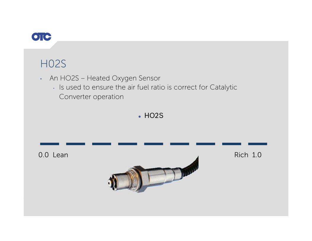
H02S • An HO2S – Heated Oxygen Sensor
• Is used to ensure the air fuel ratio is correct for Catalytic Converter operation
l HO2S
0.0 Lean Rich 1.0

H02S • HO2S sees 0.0 volts lean
• IPW will be wide • Providing CO - Carbon Monoxide to cause the oxidation
process to begin • HO2S see 1.0 volt rich
• IPW will be narrow • Providing O2 – Oxygen to replenish the O2 used during the
Oxidation process
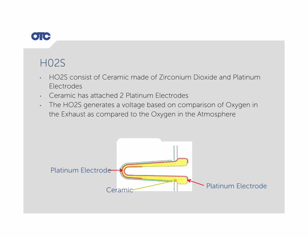
H02S • HO2S consist of Ceramic made of Zirconium Dioxide and Platinum
Electrodes • Ceramic has attached 2 Platinum Electrodes • The HO2S generates a voltage based on comparison of Oxygen in
the Exhaust as compared to the Oxygen in the Atmosphere
Platinum Electrode
Ceramic Platinum Electrode

H02S • One end of the Ceramic/Platinum combination is exposed to the
Exhaust • The other end of the Ceramic/Platinum combination is exposed to
the Atmosphere
Atmosphere air

H02S • When the O2 in the exhaust gas is low, the sensor voltage is high
indicating a Rich condition • The greater the difference in O2 in the Atmosphere versus the
exhaust the higher the voltage • The Atmospheric O2 wants to travel towards the O2 starved
Exhaust, this movement of the O2 creates a high voltage
O O
O O
O O
O O
O O
O O
O O
O
O O
Atmosphere air
O O O O O O O
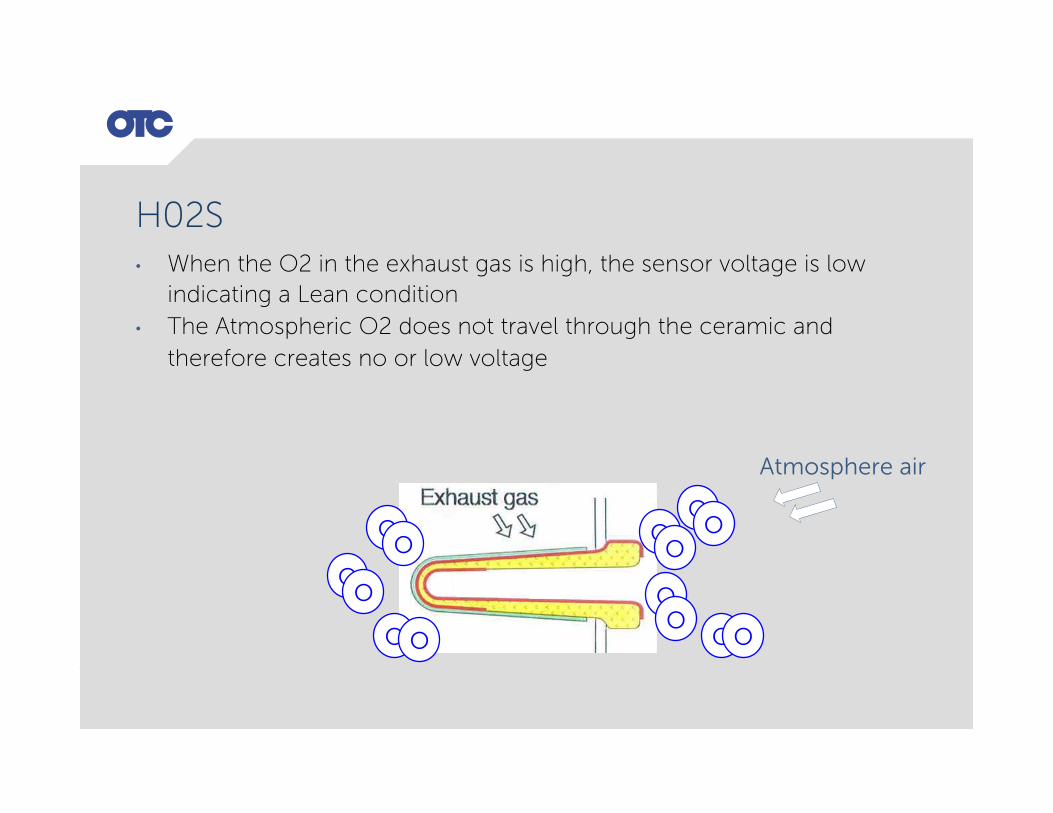
H02S • When the O2 in the exhaust gas is high, the sensor voltage is low
indicating a Lean condition • The Atmospheric O2 does not travel through the ceramic and
therefore creates no or low voltage
O O
O O
O O
O O
O O
O O
O O
Atmosphere air
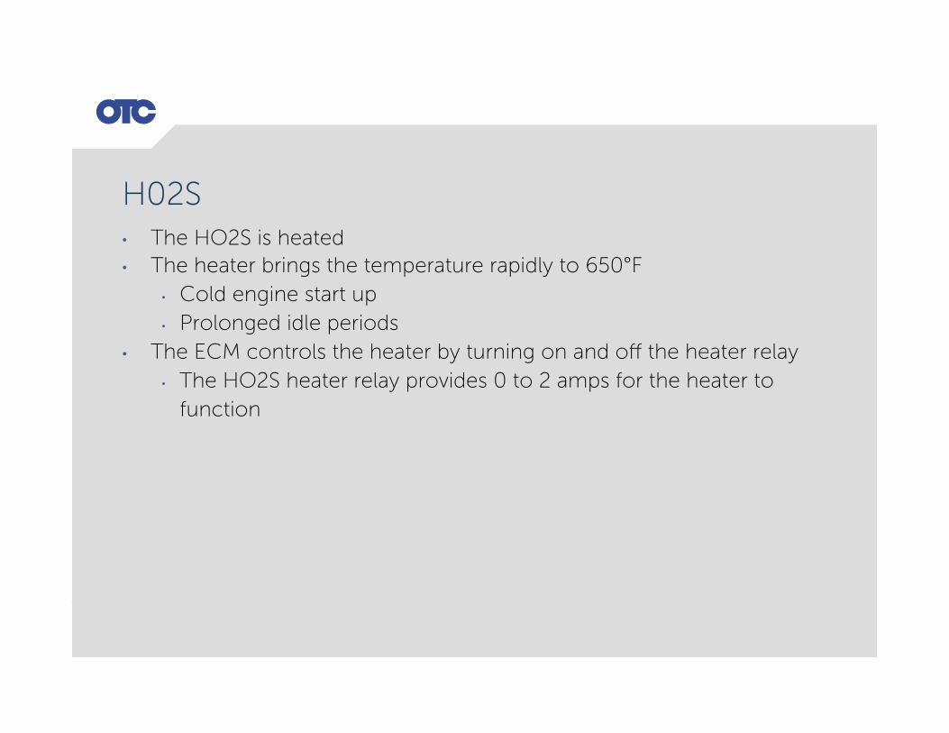
H02S • The HO2S is heated • The heater brings the temperature rapidly to 650°F
• Cold engine start up • Prolonged idle periods
• The ECM controls the heater by turning on and off the heater relay • The HO2S heater relay provides 0 to 2 amps for the heater to
function

H02S • On V engine
• B1 S1 Bank One Sensor One • B1 S2 Bank One Sensor Two • B2 S1 Bank Two Sensor One • B2 S2 Bank Two Sensor Two
• S2 – Sensor Two is used to report Catalyst efficiency

How to Test an HO2S

H02S Test 1 • Graph HO2S Bank 1 Sensor 1 • Specification for Good O2 Sensor: 10 cycles from 200mv Lean to
800mv Rich and then Rich to Lean in 1 second, at 2000 RPM hot engine
• Datastream should display a minimum of four O2 Sensor cycles from 200mv Lean to 800mv Rich and then Rich to Lean, at 2000 RPM hot engine

HO2S Propane Test 2 • O2 Sensor propane enrichment test • Graph the front O2 sensors • Add propane to enrichment the mixture • Propane enrichment will increase the O2 voltage which will rise
towards or above .8 volts • Keep adding propane until RPM drops, to obtain maximum output • Shut off the propane to see how fast the voltage decreases • It should decrease rapidly towards a Lean signal
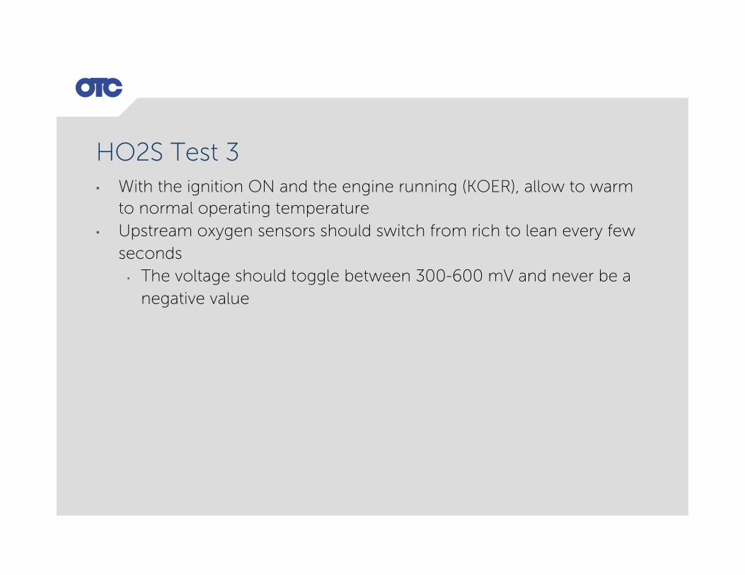
HO2S Test 3 • With the ignition ON and the engine running (KOER), allow to warm
to normal operating temperature • Upstream oxygen sensors should switch from rich to lean every few
seconds • The voltage should toggle between 300-600 mV and never be a
negative value

What is an AFR?

• An AFR – Air Fuel Ratio sensor is a wide band Oxygen sensor • It has a wide voltage range to make its measurements
• This provides for more accurate calculation of fuel metering by the PCM – Powertrain Control Module
• More points on the AFR scale gives the PCM more points to set IPW – Injector Pulse Width • It design makes it fast acting allowing the PCM to make fast decision • An HO2S and an AFR look similar, but have different connectors
0.00 Rich Lean 5.00
0.0 Lean Rich 1.0
AFR
HO2S
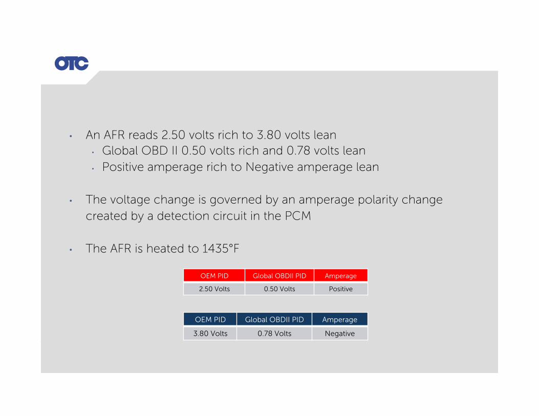
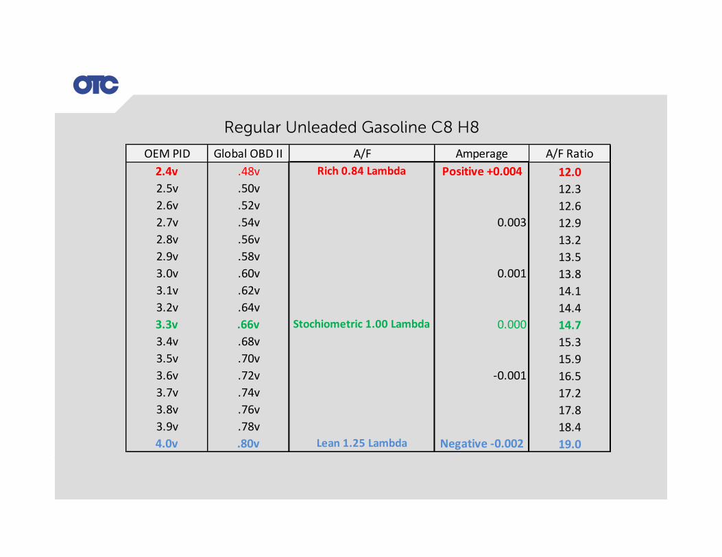
• An AFR reads 2.50 volts rich to 3.80 volts lean • Global OBD II 0.50 volts rich and 0.78 volts lean • Positive amperage rich to Negative amperage lean
• The voltage change is governed by an amperage polarity change created by a detection circuit in the PCM
• The AFR is heated to 1435°F
OEM PID Global OBDII PID Amperage
2.50 Volts 0.50 Volts Positive
OEM PID Global OBDII PID Amperage
3.80 Volts 0.78 Volts Negative

How does an AFR work?
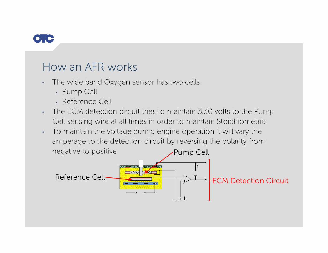
How an AFR works • The wide band Oxygen sensor has two cells
• Pump Cell • Reference Cell
• The ECM detection circuit tries to maintain 3.30 volts to the Pump Cell sensing wire at all times in order to maintain Stoichiometric
• To maintain the voltage during engine operation it will vary the amperage to the detection circuit by reversing the polarity from negative to positive
ECM Detection Circuit
Pump Cell
Reference Cell

How an AFR works • The Pump Cell current flow pushed the Exhaust in and out of the
Pump Cell • Once the analysis has been completed the Pump Cell expels the
Exhaust • This is a constant ongoing circulation • The change in exhaust oxygen is always being detected
Exhaust
Pump Cell

How an AFR works • If the exhaust is rich containing less oxygen the voltage will fall to as
low as 2.50 volts • The amperage will be positive to try to maintain 3.30 volts
• Air fuel ratio as rich as 12:1
• The ECM decrease IPW based on a decision made from the amount current flowing
OEM Global Amperage Condition Lambda A/FRatio IPWCorrect2.50v 0.48v 0.004 Rich 0.84 12to1 Lean
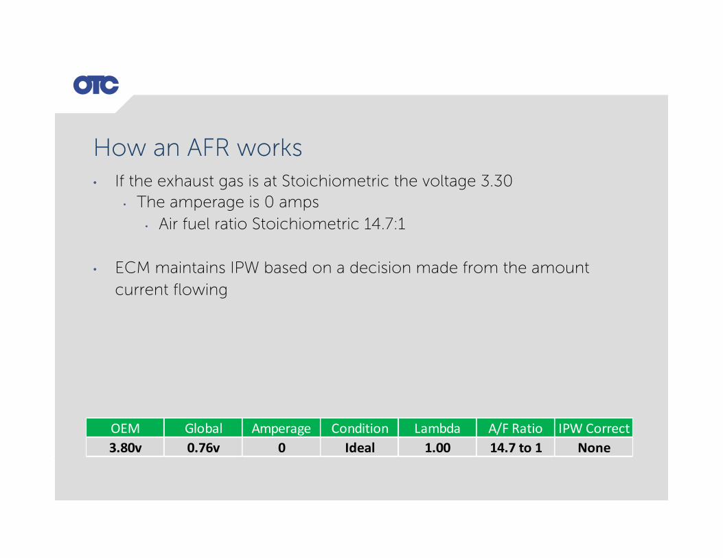
How an AFR works • If the exhaust gas is at Stoichiometric the voltage 3.30
• The amperage is 0 amps • Air fuel ratio Stoichiometric 14.7:1
• ECM maintains IPW based on a decision made from the amount current flowing
OEM Global Amperage Condition Lambda A/FRatio IPWCorrect3.80v 0.76v 0 Ideal 1.00 14.7to1 None

How an AFR works • If the exhaust is lean containing a lot of oxygen the voltage will rise
to as high as 3.80 volts • The amperage will be negative to try to maintain 3.30 volts
• Air fuel ratio as lean as 19:1
• The ECM increases IPW based on a decision made from the amount current flowing
OEM Global Amperage Condition Lambda A/FRatio IPWCorrect3.80v 0.76v -0.001 Lean 1.20 19to1 Rich
OEMPID GlobalOBDII A/F Amperage A/FRatioRich0.84Lambda Positive+0.004
0.003
0.001
Stochiometric1.00Lambda 0.000
-0.001
Lean1.25Lambda Negative-0.002
12.012.312.612.913.213.513.814.114.414.715.315.916.517.217.818.419.0
2.4v2.5v2.6v2.7v2.8v2.9v3.0v3.1v3.2v3.3v3.4v3.5v3.6v3.7v3.8v3.9v4.0v
.48v
.50v
.52v
.54v
.56v
.58v
.60v
.62v
.64v
.66v
.68v
.70v
.72v
.74v
.76v
.78v
.80v
Regular Unleaded Gasoline C8 H8

The AFR Heater
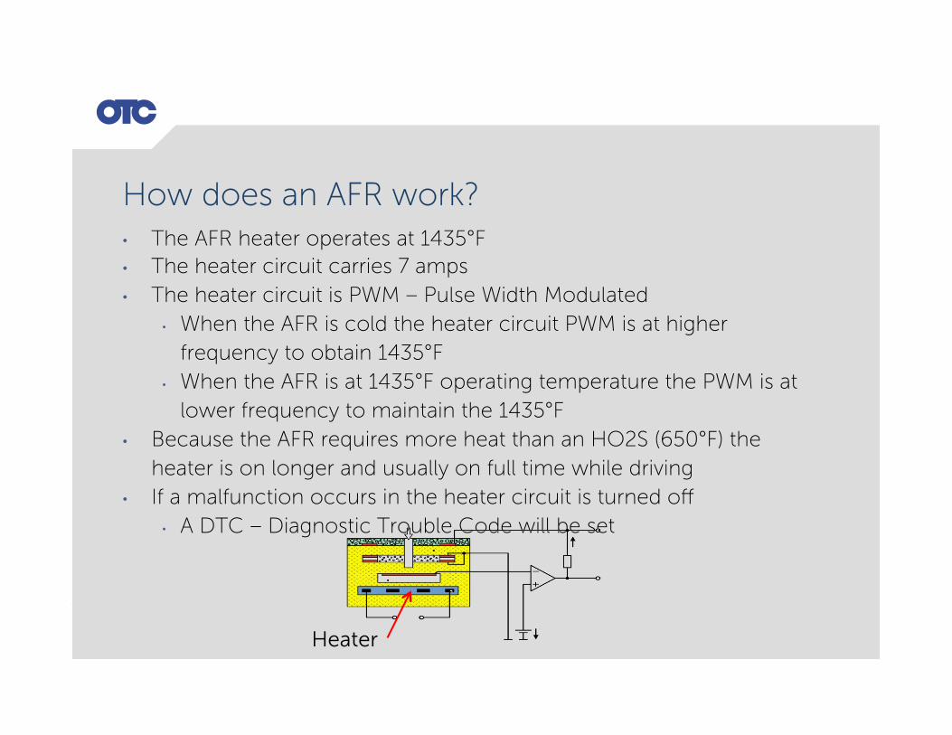
How does an AFR work? • The AFR heater operates at 1435°F • The heater circuit carries 7 amps • The heater circuit is PWM – Pulse Width Modulated
• When the AFR is cold the heater circuit PWM is at higher frequency to obtain 1435°F
• When the AFR is at 1435°F operating temperature the PWM is at lower frequency to maintain the 1435°F
• Because the AFR requires more heat than an HO2S (650°F) the heater is on longer and usually on full time while driving
• If a malfunction occurs in the heater circuit is turned off • A DTC – Diagnostic Trouble Code will be set
Heater

How to Test an AFR

AFR Sensor Test 1 • Engine at operating temperature • No DTC’s present for AFR or AFR Heater circuit • From idle raise engine to 2500 RPM • AFR should read 3.30 volts • Snap the throttle to 4000 RPM
• AFR voltage will fall Rich
• After throttle is closed and at return to idle • AFR voltage should rise Lean
• If no change check AFR heater circuit • Always verify AFR specification with Identifix
OEM PID Global OBDII PID Amperage
2.50 Volts 0.50 Volts Positive
OEM PID Global OBDII PID Amperage
3.80 Volts 0.78 Volts Negative

AFR Sensor Test 2 • Engine at operating temperature • No DTC’s present for AFR or AFR Heater circuit • Create a Vacuum Leak
• Lean condition • Voltage should rise • Amperage should drop

AFR Sensor Test 3 Toyota • Engine at operating temperature • No DTC’s present for AFR or AFR Heater circuit • Special Tests
• AFR Test • Activate
• IPW will increase automatically • AFR voltage should drop with IPW increasing
• IPW will then decrease automatically • AFR voltage should rise with IPW decreasing

What is Fuel Trim?

What is Fuel Trim? • Fuel Trim is the corrections the PCM is commanding • Specification: ±5%
• STFT – Short Term Fuel Trim – immediate correction about 20 time per second • change rapidly in response to the HO2S/AFR inputs and or MAF and
or RPM • These changes fine tune the engine fueling
• LTFT – Long Term Fuel Trim – long term correction about 2 times per second • The Long Term Fuel Trim values change in response to trends in
Short Term Fuel Trim • The Long Term Fuel Trim makes coarse adjustments to fueling in
order to re-center and restore control to Short Term Fuel Trim

What is Fuel Trim? • +10, + plus numbers on STFT means the PCM has
received a lean signal from the AFR or HO2S • PCM will command the Injector Pulse Width to widen for a rich
correction
• -10, - minus numbers on STFT means the PCM has received a rich signal from the AFR or HO2S • PCM will command the Injector Pulse Width to narrow for a lean
correction

Diagnosing with Fuel Trim

Fuel Trim Diagnostics
Idle 2500 RPM Possible Causes
+ 5% and Up 0% Vacuum Leaks
0% + 5% and Up Low Fuel Volume
+ 5% and Up + 5% and Up Low Fuel Pressure
-5% and lower 0% Contaminated Crankcase
-5% and lower -5% and lower Injectors

Catalytic Converter

O
O O
O O2 SENSOR READS LEAN, PCM COMMANDS RICH, INCREASING CO
200mv SWITCH <100ms
C
O
H
C
N
O
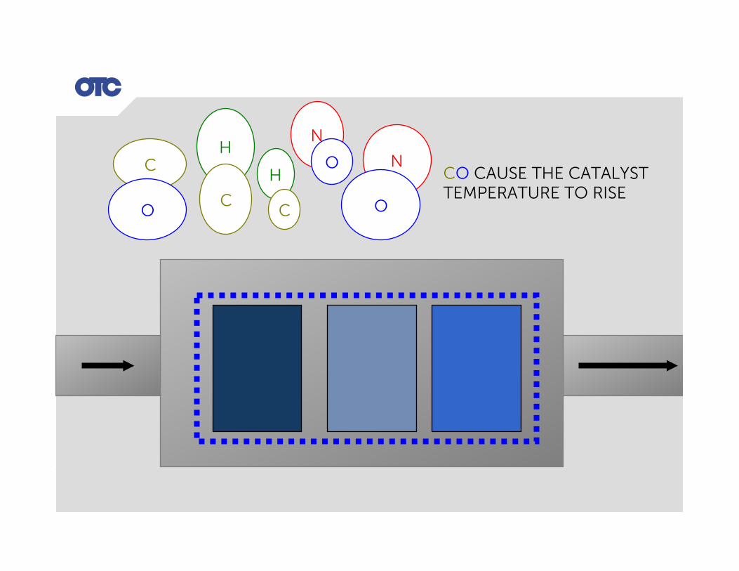
CO CAUSE THE CATALYST TEMPERATURE TO RISE
N
O H
C
C
O
H
C
N
O
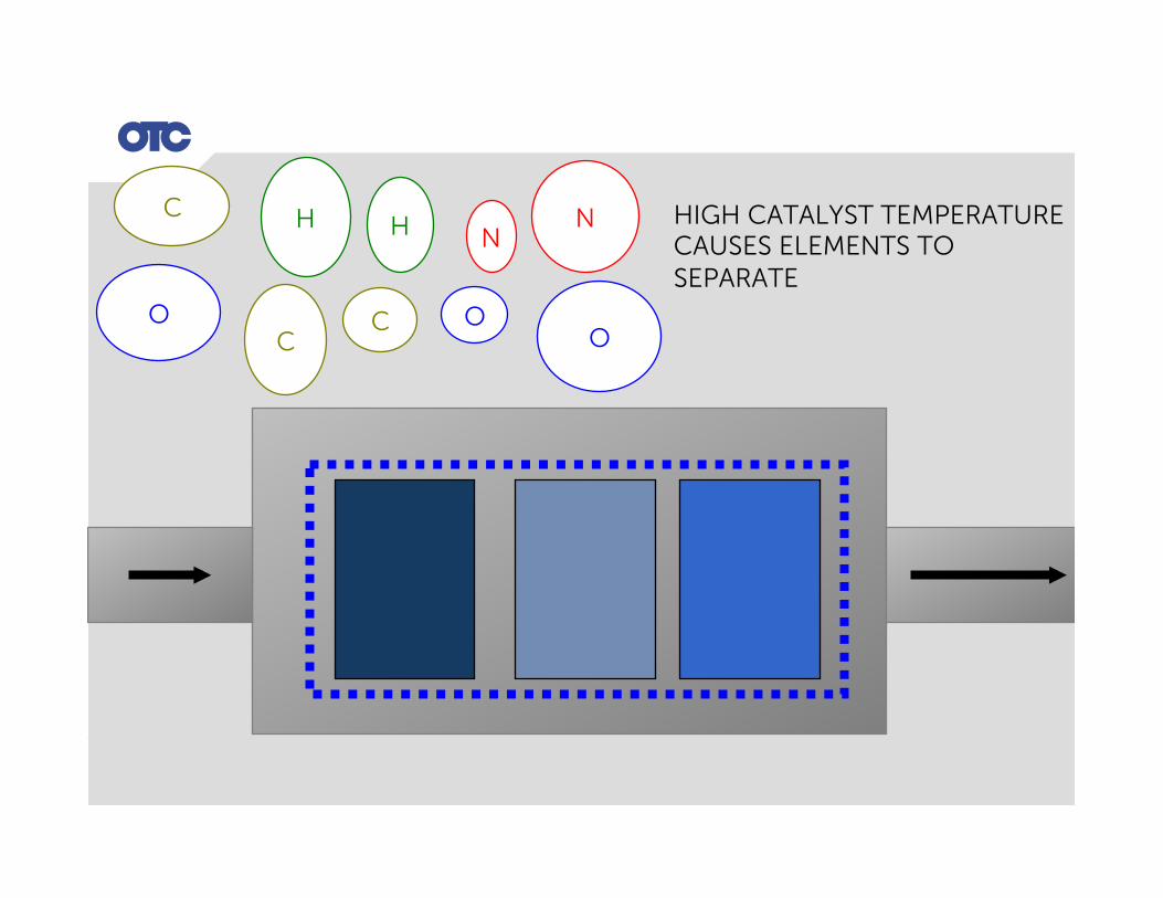
HIGH CATALYST TEMPERATURE CAUSES ELEMENTS TO SEPARATE
H
C
N
O

C
O
H
C
N
O
H
C
N
O
O2 FROM CERAMIC SUBSTRATE COMES OUT
O O O O
O
H
H C O
N N
O
C
O
O C
O
O
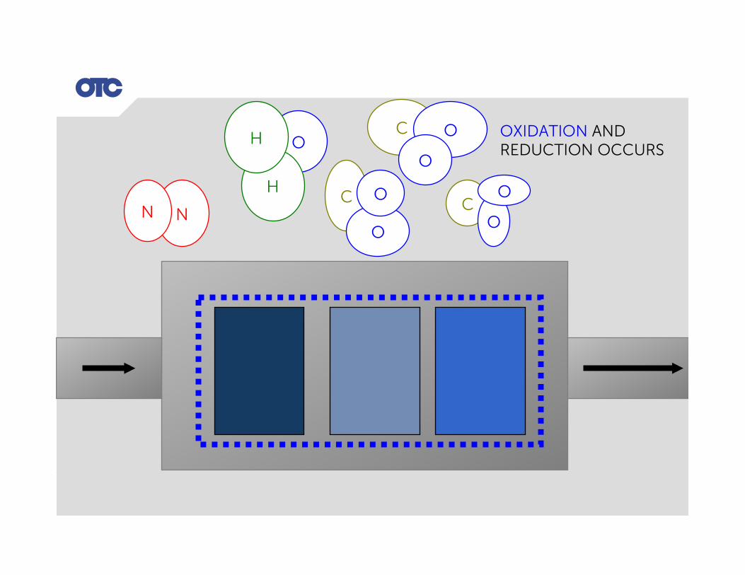
OXIDATION AND REDUCTION OCCURS

O2 SENSOR READS RICH , PCM COMMANDS LEAN, REPLENISHING CATALYTIC CONVERTOR WITH O2
800mv SWITCH <100ms

Ethanol Blended Fuels
Air Fuel Ratio for Ethanol Blended Fuels • Most of North America uses Ethanol blended fuel
• Reduces America’s foreign dependence on Oil • Typically used is a 10% blend of Ethanol – E10
• C2 H5 OH • Octane 95

Air Fuel Ratio for Ethanol Blended Fuels • Air Fuel Ratio
• Stoichiometric Air Fuel Ratio for 100% Ethanol is 9.00:1 • Stoichiometric Air Fuel Ratio for Gasoline is 14.7:1
• If you blended volume of Ethanol is 10%, then to calculate your AFR use the following formula: • 90% Gasoline 14.7x 0.90 = 13.23 AFR • 10% Ethanol 9.00 x 0.10 = 0.90 AFR
• (14.7 x 0.90) + (9.00 x 0.10) = 14.13 AFR • Rounded up to 14.2 AFR
Condition Lambda A/FRatio IPWCorrectIdeal 1.00 14.2 None

Air Fuel Ratio for Ethanol Blended Fuels • To calculate WOT AFR:
• Ethanol blended fuel 14.2 AFR • Lambda at WOT 0.84
• AFR would be 14.2 x 0.84 = 11.928 AFR • Round up to 11.9 AFR at WOT
Condition Lambda A/FRatio IPWCorrectRich 0.84 11.9 Lean

Air Fuel Ratio for Ethanol Blended Fuels • To calculate lean AFR:
• Ethanol blended fuel 14.2 AFR • Lambda when lean 1.25
• AFR would be 14.2 x 1.25 = 17.75 AFR lean • Round up to 17.8 AFR lean
Condition Lambda A/FRatio IPWCorrectLean 1.25 17.8 Rich

What have we learned? • What is a HO2S and how does it work • How to test a HO2S Sensor • What is a AFR sensor • How to test a AFR sensor • How a AFR Heater works • What is STFT and LTFT • How to use STFT and LTFT to assist your diagnosis • How an AFRHO2S has effect on Catalytic Converter Function • Ethanol Blended Fuels and how they may affect your diagnosis


![[AFR] Revista AFR Nº 093](https://static.fdocuments.us/doc/165x107/577d26191a28ab4e1ea0465c/afr-revista-afr-no-093.jpg)


