HLëS, WHEELS AND ÏYRES - UNIGE
12
Section G.1. G.2. G.3. G.4. G.5. G.6. G .7. G.8. SECTION G HLëS, WHEELS AND ÏYRES Descriptïon General Descriptîon PageNo. 3 Front Hubs - Adiust Fronf Hubs - Remove and Replace Rear Hubs & Outboard Drive Shafts Remove and Replace Rear Hub Bearings Wheel Drive Pegs Wheels Tyres Additional Information 12. 1170
Transcript of HLëS, WHEELS AND ÏYRES - UNIGE

Section
G.1.
G.2.
G.3.
G.4.
G.5.
G.6.
G .7.
G.8.
SECTION G
HLëS, WHEELS AND ÏYRES
Descriptïon
General Descriptîon
Page No.
3
Front Hubs - Adiust
Fronf Hubs - Remove and Replace
Rear Hubs & Outboard Drive ShaftsRemove and Replace
Rear Hub Bearings
Wheel Drive Pegs
Wheels
Tyres
Additional Information 12.
1170
P AGE 2. a'aECTIONGHUBS i WHEELSANDTYREa -
Fig. Nos. Description.
ILLUS TR ATIONS.
Page No.
1.
2.
7.
Cross Section of Front Hüb.
Adjusting Front Hub.
Front Jack Location.
Rear Jack Location.
Cross Section of Rear Hub.
Wheel Drive Pegs.
Wheel Nut Spanner.
I

SECTIONG-HUBS î WHEELSANDl"YRES - PAC J E3.
G. 1 - GENERAL DESCRIPTION.
'Knock - on' centre lock wheels, of either pressed steel or alloy construction(depending on model) are fitted to all models. It is essential to use the correctnut with the appropriate wheel. The spare wheel is located in the luggagecompartment below the floor on the left - hand side and is retained by a clampand bolt.
Radial ply tyres (with inner tubes where applicable) of Firestone, Goodyearor Dunlop manufacture have been fitted as original equipment depending on theiravailability. Tyre pressures should be maintained at the pressures given in'TECHNICAL DATA' and should be checked every 1,OOO miles (1,600 km.).
The front hubs are mounted Oh two taper roller bearings and are designed torun with a specified end float (see 'TECHNICAL DATA'). Overtightening willdestroy the bearings.
The rear hub bearings consist of ball races pressed into the bearing housingand located by circlips.
G. 2 - FRONT HUBS.
1. Loosen the road wheel securing nut.2. Apply the handbrake and raise the front of the car on a suitable jack.
Place chassis stands in position then remove jack.3.. Remove the wheel securing nut and take off wheel.4. Extract the split pin locking the hub securing nut and discard.5. Mount a dial ç4auge in such a position that its plunger is against the front
face of the hub. Tighten the securing nut sufficiently to give an indicatedend float (see 'TECHNICAL DATA' ), back off the nut one flat (60o), theninsert a new split pin to lock.
6. Repack hub with grease (see Section 'O'), working the grease well past thelarge washer below the securing nut. Only HALF FILL THE HUB to allowfor expaasion.
7. Replace the wheel, ensuring that the drive pegs are fully located BEFOREfitting wheel nuts, which must be assembled DRY. :Do NOT gre:se or oil
' S. Repeat above procedure f or opposit e wheel .the threads.

PAGE4. SECTION G - HUBS, WHEELS AND TYRES.
rc - G0 - C, I
Fig, 3. FRONT JACK LOCATION
PAGE 5., SECTION G - HUBS, WHEELS AND TYRES,
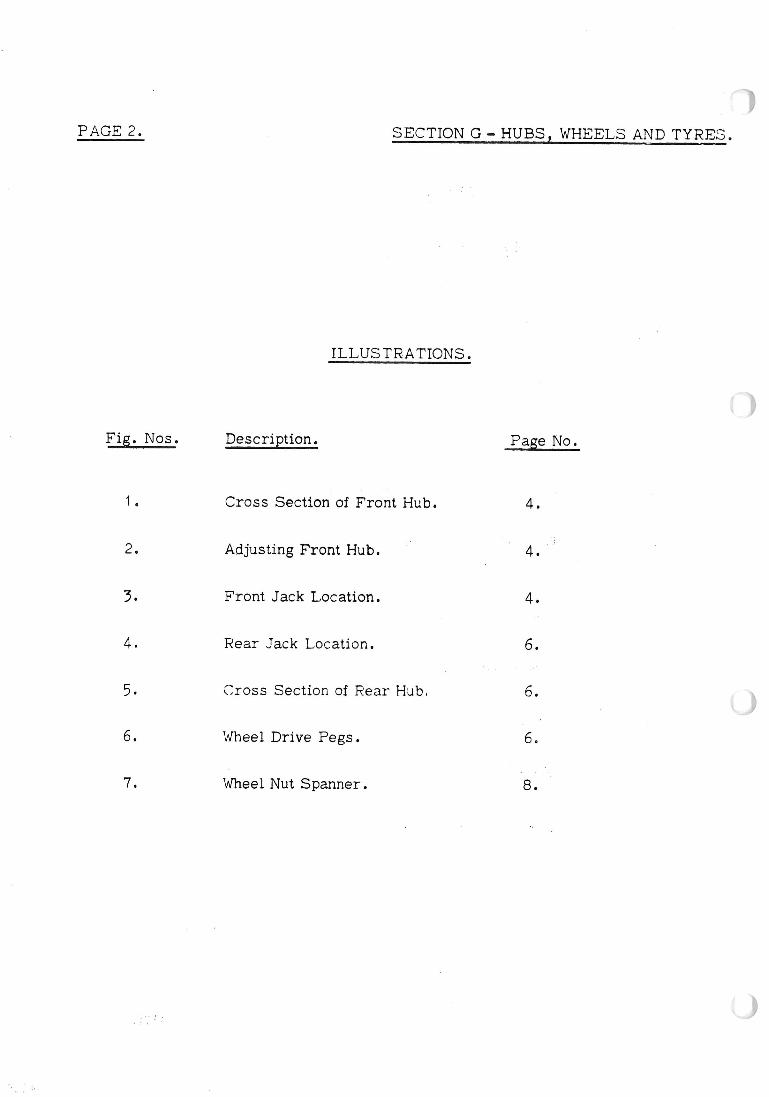
G. 3 - FRONT HUBS.
To Remove.
1. Remove the road wheel (Section 'G. 2').2. Break the fluid supply to the front caliper at its connection. Fit plug'to
pipe to avoid ingress of dirt,
5. Detach the brake caliper (see Section 'J').4. Remove the split pin locking the securing nut and discard. Remove nut and
washer,
5. From the rear of the brake disc, remove the bolts which retain both discand hub. Pull off hub.
To Replace.
1. Clean the mating faces of the hub and disc. These must be scrupulouslyclean if disc run-out is to be avoided.
2. Replace the bearings as necessary.
3. Fit the hub and disc assembly, tightening the securing bolts to the torqueloading given in 'TECHNICAL DATA'. Secure the hub with its nut andsplit pin repacking with gï'eaSe and adjusting end- float (Section IG.21).
4. Refit the caliper. Remove plug from pipe end and refit pipe to caliper.Tighten pipe nut to the torque loading given in 'TECHNICAL DATA'.Bleed the brakes (see Section 'J').
5. Replace the road wheels and lower car to ground aîter removing chassis stands.
G. 4 - REAR HUBS AND OUTBOARD DRrVE SHAFTS.
To Remove.
1. Loosen the road wheel securing nut.
2. Rai se the rear of the car and support with chassi s stand,i , tï eù rpmove jack.'3. Remove the wheel securing nut and take off wheel. Remove the hub securing

PAGE 6. SEC'i'IONG-HUBSyWHEEL,SANDTYRES.
:,Jfr
50/OH{6
Fig, 4. REAR JACK LOCATION ÏC- Sô - (iS
Fig.5. CROSS SECTION OF REAR HUeitC-«#-46.
FIg. â WHEEL DRIVE PEGS
I
i SECTION G - HUBS, WHEELS AND TYRES. PAGE7.
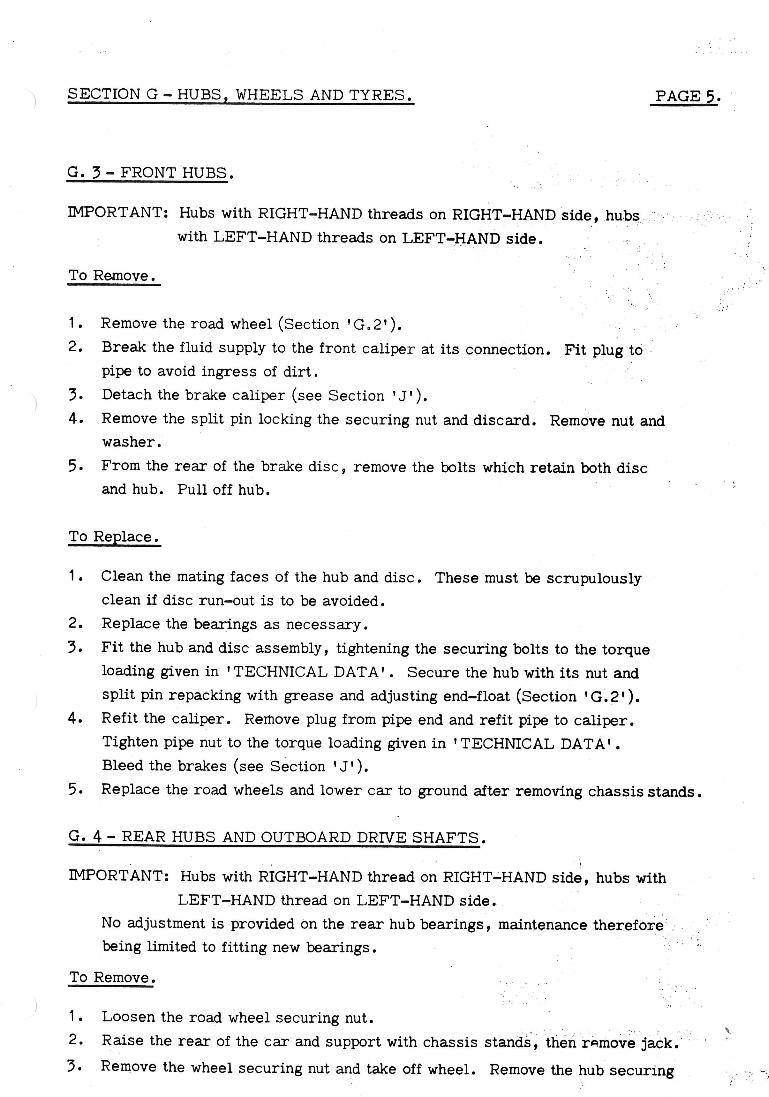
nut wïth its wcisher.
4. Using CI suitable ex+ractor, pull off +he hub. lJse adaptors X036 T 0285 L/H and
X036 T 0286Z R/ H, together with extractor IS1 090'. The extractor is avaNable
from V.L.Churchill & Co. L+d., London Road, Daven+ry, Northamptonshire,EngIand.
5. To remove +he bearings, it is necessary to first remove +he outboard drive shaft by releasing
the three bol+s securing it +o +he Rotoflex coupling. Remove +he circlip from the inner
bearing and push out the drive shaft and inner bearing. Remove the inner bearing locating
circlips From the shaft and drive the bearïng off the shaf+.
To Reploce.
1. Replacîng the bearings is a reversal of +he removal procedure.lt is suggested tha+ whilst'
the bearîngs are of the sealed +ype, it is advisable to grease the internal surfaces of the
bearing housing to help prevent corrosion. Loca+e the outboard drive shcif+.
2. Lïning- up the keyway, push on the rear hub and secure with nuj (Part No. A036 D 6019)
and washer. Tïghten +he nu+ to the +orque loading given in 'TECHNICAL DATA'.
3. Replace +he road wheel and lower car after removing chossïs stands.G .5. - REAR HUB BEARINGS.
Commencing CI+ ChaSSiS No. 50/0250, modifïed INNER bearings (36 D 6003)
were fi+ted to overcome possible failure due +o ingress of dirt and /or moisture.
Modified OUTER bearings (36 D 6016) hove been fitted since Chassis No. 50/0870,
Thesè bearings will give a longer life expec+ancy +han +hose previously specified.G .6. - WHEEL DRIVE PEGS.
If the occassion arises where it ïs necessary to change the wheel drive pegs, i+
is pointed out tha+ these have an interference fit in the hubs. When renewing +herefore, heat
the hub sufficien+ly +o enable +he new pegs +o be driven în with modera+e force without impairingthe interference fi+.
G .7. - WHEELS
S.M.M.T. (Socie+y of Motor Manufacturers and Traders) standard tolerances of
the wheel only are :ao
a. Wobble
The laterol voriatïon measured on +he vertical inside foce of o flonge must NOT EXCEED
.05 in. (1.27 mm.).
+2 1072,

PAGE 8. SECTION G - HUBS, WHEELS AND TYRES,
b. Lift.
The difference between the high and low points of a rotating wheel measuredat any location on either bead seat must NOT EXCEED .05 in, (1.27 mm).Lateral and radial inaccuracies outside these limits contribute respectîvelyto dynamic and static unbalance.
Severe eccentricity intermittently increases the load on the tyre and resultsin irregular wear. Static and dynamic balancing will NOT rectify thiscondition.
Wheel Alignment.
Settings for front and iear wheel alignment are given in 'TECHNICAL, DATA'Excessive misalignment caused by kerb impact or other accidental damage willresult in severe tyre wear and faulty steering.
St.eel Wheels Maintenance.
l
Ensure that the bead seats and flange îaces are kept free from rust and dirtand that wheels having damaged or elongated drive peg holes are replaced.
Locally damaged flanges nay be corrected by careful hammering, but abuckled wheel, i.e. one which no longer conforms to the tolerances quoted, mustbe rcplaced.
Alloy Wheels Maintenance.
The informat.ion under the previous heading also applies except, if the wheelis damaged we do NOT recommend hammering to correct damaged flanges.Change the wheel.
Clean off any corrosion to the bright parts with metal polish or wire wool.Salt water should be washed off as soon as possible.
Wheel Removal.
1. Slacken the nut of the
desired wheel usingeither the special mallet
(for 'ear - type' nuts),or spanner (for 'hqxagontype' nuts) supplied withthe car. Nuts on LEFT-
HAND side of car are
released in a CLOCKWISF
direction, while nuts on F C, 7 WHEEL NUÏ SPANNER

SECTION G - HUBS, WHEELS AND TYRES. PA( J E 9.
RIGHT- HAND side are released in an ANTI (COUNTER) - CLOCKWISEdirection.
Raise the vehicle and fully release the wheel nut. Pull off wheel.
When replacing the wheel, ensure that it is fully seated on the hub and on
the drive pegs BEFORE replacing the nut. Do NOT grease or oil thethreads on either the hub or the wheel nut, just clean.
Wheel Nuts.
It is PORTANT to note that the wheel nuts used for steel and alloy
wheels are NOT interchangeable.
Check security of wheel nuts at between 5 and 10 miles (8 and 16 km.) afterinitial fitting, and thereafter every 1 , OOO miles (1 , 600 km. ) or weekly,whichever occurs first.
G .8 - TYRES.
Tyre Care.
Check at intervals of every 1,OOO miles (1,600 km.) that the tyre pressuresare correct.
Ensure that the tyres are cold when checking the pressures. Never bleed
air out of a warm tyre in order to achieve the recommended pressure, since
when the tyre cools it will be under - inflated.
If oil or grease have been in contact with a tyre wipe the affected area witha cloth lightly moistened with petrol or trichloroethylene.
New Tyres.
When new tyres are required it is essential to fit the same type as those
remaining on the vehicle. The characteristics of tyres vary considerably,
theretore, if tyres are changed for those cî a different type, then it is imperative
that all tyres including the spare, are changed at the same time.If trouble is experienced with replacement tyres, reference should be made
to the manufacturers concerned.
Inflation Pressures.
Severe and persistent under - inflation produces unmistakeable evidence onthe tj!lread. It also causes structural failure due to excessive friction and
temperature within the casing.
Pressures higher than those recomÏnended reduce tread life by concentrating

PAGE10. -C=ECTION G HUBS ? EELS AND TYRES -
the load on a small tread area. Excessive pressures overstrain the casing,cause rapid wear and make the tyres more susceptible to impact fractures andcuts.
Effect of Temperature.
Air expands with heating and tyre pressures increase as the tyres warm up.Pressures increase more in hot weather than in cold weather and as a result
of high speed.
Pressure in warm tyres should not be redured to standard pressure for
cold tyres. 'Bleeding' the tyres increaseü rlîeir deflections and causes their
temperatures to climb still higher. The tyres will also be under - inflated when
they have cooled.
The rate of tread wear rri ay be twice as fast at 50 m.p.h. (80 k.p.h.) as at:50 m. p. h. (48 k. p. h. ).
High speed causes increased temparatures due to more deflections per
minute and a faster rate of deflection and recovery. The resistance of the tread
to abrasion decreases with increased tyre tenipera.ture.
l
Camber, Castor and King Piü Inclination (see also Section 'C').
These angles normally require no atterîtion uriless they have been disturbed
by a severe impact or abnormal v.'car of front. end bearings. It is always advisable
to check them if steering irregularities develop.
Wheel camber, usually combined with road camber, causes a wheel to try to
turri in the direction of lean, due to one side of the tread attempting to make more
revolutions per mile than the other side. The resulting increased tread shuffle
on the road and the off - centre tyre loading tend to cause rapid and one - sided
wear. Unequal cambers introduce un'balanced forces which try to steer the car
one way or the other. This must be countered by steering in the opposite
direction which increases tread wear.
Castor and king pin inclination by themselves have no direct bearing on tyre
wear but their measurement is often useful for providing a general indication of
the condition of the front end geometry and suspension.
l
Braking.
Irregular braking torque produces excessive local tread wear generally
caused by eccentric brake discs OÏ' the use of incorrect pad lining materials.
' Spotty' wear may be due to a variety of faults, and if pre'sent, the following
items should be checked: -

SECTION G - HUBS, !fflEELS AN:[) TYRES. PAGE 11
Inflation pressure.
eel balance.
Steering swivels for wear.
Wheel hub bearing condition and adjustment.
Wheel alignment.
Wheel Alignment and Road Camber.
Fins and feathers on the tread surface are due to severe wheel misalignmentThe condition takes the form of a sharp 'fin' on the edge of each pattern rib andthe position of this indicates the direction of misaligmnent.
Excessive TOE - IN will cause fins on the INBOARD edges of the pattern rib.Excessive TOE - OUT will cause fins on the OUTBOARD edges of the patternrib.
NOTE: Finning on nearside front tyre ONLY may be due to severe road
camber conditions and cannot be eliminated by rnechanical adjustment. Inthis event frequently change the position of the affected wheel.
Tyre and Wheel Balance.
The original degree of balance is not necessarily maintained', and it may beaffected by uneven tread wear, by repairs, by tyre removal and refitting or bywheel damage and eccentricity. The vehicle may also become more sensitive tounbalance due to normal wear of moving parts.
If roughness or steering troubles develop and mechanical investigation failsto disclose a possible cause, wheel and tyre balance should be suspected. Staticunbalance can be measured when the tyre and wheel assembly is stationary.
Dynamic unbalance can be detected only when the assembly is revolving.There may be no heavy spot, that is, there may be no natural tendency for
the assembly to rotate about its centre due to gravity, but the weight may beunevenly distributed each side of the tyre centre line. Laterally eccentric wheelsgive the same effect. During rotation the offset weight distribution sets up arotating couple which tends to steer the wheel to left and right alternatively.Dynamic unbalance of tyre and wheel assemblies should be measured on a BalancingMachine and suitable corrections made when the vehicle shows sensitivity to thisform of unbalance. Where it is clear that a damaged wheel is the p:iimary causeof severe ünbalance it is advisable to renew the wheel.
It is recommended that the complete assembly of wheels and tyres arebalanced at intervals of every 3, OOO miles (5, OOO km. ).
PA( J E12. SECTION G - HUBS, WHEELS AND TYRES.
Balance Weights.
When balancing alloy wheels it is IMPORTANT to use only the specified type
of weight. These axe of the 'stuck - on' type. Do NOT use the 'knock - on' type
(normally used vith steel wheels) on alloy wheels.
ADDITIONAL INFORMATION
Rear Hub Re%>val
In Sec'tfton 'Ga4', paragraph '4' of the rear hub removal procedure,
a suitable eïtractor is available under Part NC)a is ii üogor from
V&L.CHURCHILL » Co.Ltd, London Road, Daventry, Northamptonshire,
England.
I
The extractor should be used in conjunction with adaptors 36 T 285 LH
and 36 T 286 RH, these being obtainable from the Parts Division of Lotus
Cars (Service) Limited.
Re4r Hub Replpcement
Before replacing the bearings, it is necessary to trim flush the
surplus seal which stands proud of the outer race on the inner bearing
(nearest to the: drive flange coupling), so that the spacer and retaining
circlip may be fitted correctly ii
1070