HL05 – Sharp-crested weir in a rectangular...
3
HL05 – Sharp-crested weir in a rectangular flume by Gilberto E. Urroz, October 2010 Introduction A sharp-crested weir consists of a thin wall placed across an open channel. In this lab, we will place a sharp-crested weir across the rectangular Teaching Flume in the CEE Hydraulics Laboratory, as illustrated in Figure 1, below. Sharp-crested weirs are used to measure flow in open channels. Figure 1. Picture the Sharp-Crested Weir device in the Teaching Flume Theory Normal conditions of operation of a sharp-crested weir across a rectangular channel, as in this experiment, requires the aeration of the underside of the nappe as shown in Figure 1, above, or in Figure 2 (a), below. Under normal conditions of operation the discharge Q over the weir is calculated by the equation: Q= 2 3 ⋅ C d ⋅ b ⋅ 2 ⋅ g ⋅y c 3 2 , [1] where C d = discharge coefficient, b = channel width, g = acceleration of gravity, y c = head above weir. The weir height is h, while the flow depth is y 0 . The weir head is 1
Transcript of HL05 – Sharp-crested weir in a rectangular...
HL05 – Sharp-crested weir in a rectangular flumeby Gilberto E. Urroz, October 2010
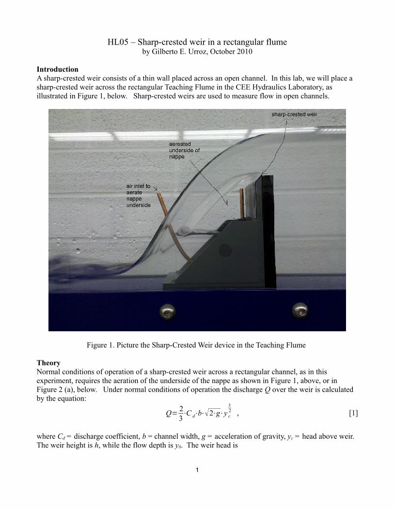
IntroductionA sharp-crested weir consists of a thin wall placed across an open channel. In this lab, we will place a sharp-crested weir across the rectangular Teaching Flume in the CEE Hydraulics Laboratory, as illustrated in Figure 1, below. Sharp-crested weirs are used to measure flow in open channels.
Figure 1. Picture the Sharp-Crested Weir device in the Teaching Flume
TheoryNormal conditions of operation of a sharp-crested weir across a rectangular channel, as in this experiment, requires the aeration of the underside of the nappe as shown in Figure 1, above, or in Figure 2 (a), below. Under normal conditions of operation the discharge Q over the weir is calculated by the equation:
Q= 23⋅C d⋅b⋅2⋅g⋅y c
32 , [1]
where Cd = discharge coefficient, b = channel width, g = acceleration of gravity, yc = head above weir.The weir height is h, while the flow depth is y0. The weir head is
1
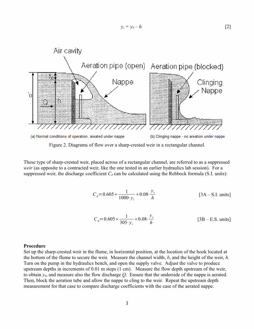
yc = y0 – h. [2]
Figure 2. Diagrams of flow over a sharp-crested weir in a rectangular channel.
These type of sharp-crested weir, placed across of a rectangular channel, are referred to as a suppressed weir (as opposite to a contracted weir, like the one tested in an earlier hydraulics lab session). For a suppressed weir, the discharge coefficient Cd can be calculated using the Rehbock formula (S.I. units):
Cd=0.605 11000⋅yc
0.08⋅yc
h [3A – S.I. units]
Cd=0.605 1305⋅yc
0.08⋅yc
h [3B – E.S. units]
ProcedureSet up the sharp-crested weir in the flume, in horizontal position, at the location of the hook located at the bottom of the flume to secure the weir. Measure the channel width, b, and the height of the weir, h. Turn on the pump in the hydraulics bench, and open the supply valve. Adjust the valve to produce upstream depths in increments of 0.01 m steps (1 cm). Measure the flow depth upstream of the weir, to obtain y0, and measure also the flow discharge Q. Ensure that the underside of the nappe is aerated. Then, block the aeration tube and allow the nappe to cling to the weir. Repeat the upstream depth measurement for that case to compare discharge coefficients with the case of the aerated nappe.
2
The following table can be used to collect your data:
Channel Width (b) = ________ m
Weir Height (h) = ___________ m
Data analysis
From Equation [1], you can write ln Q =ln 23⋅b⋅2⋅g⋅Cd
32⋅ln yc [3]
Plot ln(Q) vs. ln yc to obtain the constants K and m from Eq. [1], i.e., Q=K⋅ycm [4]
Use these results to obtain the discharge coefficient, Cd, for both the aerated and non-aerated flow conditions.
Also, calculate the discharge coefficient, Cd, according to Rehbock's formula and compare with the results obtained above.
3
aerated/non-aeratedy0 (m) yc (m) Q (m3/s)


![Riverside Topographic Assessment Methodology · The Broad Crested Weir Equation (Ref: Open Channel Hydraulics, Van Te Chow) used is listed below: Flow [m3/s] = 1.55 x breach width](https://static.fdocuments.us/doc/165x107/5f2fdad5770424727d70ba1b/riverside-topographic-assessment-methodology-the-broad-crested-weir-equation-ref.jpg)