HL-LHC Corrector Magnet 3D design status Giovanni Volpini on behalf of the LASA team CERN, February...
21
HL-LHC Corrector Magnet 3D design status Giovanni Volpini on behalf of the LASA team CERN, February 25, 2014
-
Upload
jesse-buswell -
Category
Documents
-
view
215 -
download
0
Transcript of HL-LHC Corrector Magnet 3D design status Giovanni Volpini on behalf of the LASA team CERN, February...

HL-LHCCorrector Magnet3D design status
Giovanni Volpinion behalf of the LASA team
CERN, February 25, 2014

Giovanni Volpini, CERN 25 February 2014 2
Specification done, design in progress
First tests, first experiences…
To start when a 3D em “stable” design is issued
To be done
So far, looks OK
Work status
Magnets DesignProblems waiting for us just round the (3D) corner…
magnetic lengthcross-talk between magnetsfringe field (“harmonics” at the magnet ends)forces between magnets
Residual magnetization at I=0 and impact on the harmonics
Cross check COMSOL results w/ Roxie (March 2014)
Mechanical design (May 2014)
Construction & testWind & impregnate a dummy coil (June 2014)
Design the test cryostat
Being addressed

Giovanni Volpini, CERN 25 February 2014 3
Sextupole cross-section
yoke
coil
Sextupolebore

Giovanni Volpini, CERN 25 February 2014 4
3D design: geometry
rectangular, race track, coils;iron yoke extruded;option for a stray flux return yoke investigated in the COMSOL model
COMSOL
Roxie
with flux return
without flux return
Giovanni Volpini, CERN 25 February 2014 5
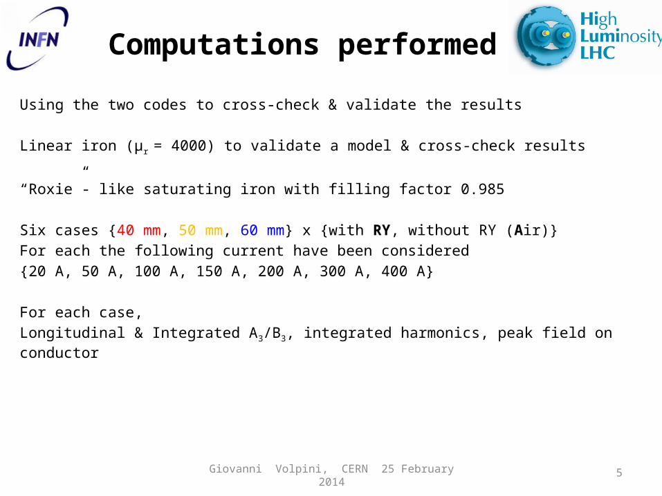
Computations performed
Using the two codes to cross-check & validate the results
Linear iron (µr = 4000) to validate a model & cross-check results
“Roxie”- like saturating iron with filling factor 0.985
Six cases {40 mm, 50 mm, 60 mm} x {with RY, without RY (Air)}For each the following current have been considered{20 A, 50 A, 100 A, 150 A, 200 A, 300 A, 400 A}
For each case, Longitudinal & Integrated A3/B3, integrated harmonics, peak field on conductor

Giovanni Volpini, CERN 25 February 2014 6
COMSOL vs Roxie
Use two codes to cross-check & validate the results:• COMSOL + Mathematica for harmonic analysis;• Roxie
2D results: agreement within few parts/104 on fields; few % on relevant harmonics. Satisfactory for our purposes.WARNING: use of LSOLV in Roxie option leads to inaccurate results, with a discrepancy w.r.t. COMSOL as large as 3% on fields.
3D results: agreement within ~1% on fields; 10% on relevant harmonics. Acceptable but not exciting.

Giovanni Volpini, CERN 25 February 2014 7

Giovanni Volpini, CERN 25 February 2014 8
0 .0 0 0 .0 5 0 .1 0 0 .1 5 0 .2 0Inte gra te d B 3 T mA
A
A
A
A
A
A
A
A
A
A
A
A
A
A
A
A
A
A
A
A
A
A
A
A
A
A
A
A
A
A
A
A
A
A
A
A
A
A
A
R Y
R Y
R Y
R Y
R Y
R Y
R Y
R Y
R Y
R Y
R Y
R Y
R Y
R Y
R Y
R Y
R Y
R Y
R Y
R Y
R Y
R Y
R Y
R Y
R Y
R Y
R Y
R Y
R Y
R Y
R Y
R Y
1 2 3 4B p e a k o n c o ils T
1 0 0 0 0
2 0 0 0 0
3 0 0 0 0
4 0 0 0 0
5 0 0 0 0
6 0 0 0 0
M a gne to mo tive fo rc e A turns Operating point & length, I
Design integrated strength 60 mT m
Desig
n o
pera
tin
g c
urr
en
t ra
tio v
s.
s.s
. lim
it (
40
%)
… vs integrated B3
…vs peak field on coils
We compute the Ic at the peak field at s.s. limit. Dividing the magnetomotive force at s.s. limit by Ic, we get the no. of turns required.Dividing the operating magnetomotive force by the no. turns, we get the operating current.

Giovanni Volpini, CERN 25 February 2014 9
WITHOUT R.Y. WITH R.Y.
Iron length [mm] 40 50 60 40 50 60
Operating magnetomot. force
[A turns] 31104 22312 18290 37919 26056 20235
Bpeak at s.s. limit [T] 4.67 3.69 3.25 5.71 4.83 3.52
Wire Ic [A] 338.4 411.1 451.4 276.5 327.6 425.4
Operating current [A] 135.4 164.5 180.6 110.6 131 170
No. Turns required [-] 228 136 101 343 199 119
Operating point & length, II
2D design was made with 166 turns x 150 A, the operating point was around the 40% on the load line.

Giovanni Volpini, CERN 25 February 2014 1010 1005020 3015 15070
z axis mm10 4
0.001
0.01
0.1
1A 3 r 50 mm T A 3 component integrated stregth 0.06 Tm
B3/A3 component inside and outside
Iron length(w.o. flux return, if present)
nominal “magnetic ½length”
(60.5 mm)
nominal spacing between magnets (100 mm)
∫−∞
∞
|𝐵3|𝑑𝑧=60mT ∙m
with flux return
without flux return
Giovanni Volpini, CERN 25 February 2014 11
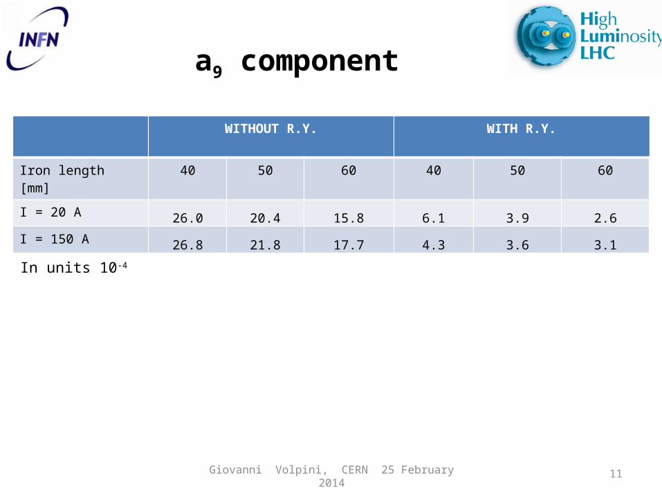
a9 component
WITHOUT R.Y. WITH R.Y.
Iron length [mm] 40 50 60 40 50 60
I = 20 A26.0 20.4 15.8 6.1 3.9 2.6
I = 150 A26.8 21.8 17.7 4.3 3.6 3.1
In units 10-4

Giovanni Volpini, CERN 25 February 2014 12
summary
For the sextupole, the overall 3D e.m. design seems compatible with the space constraints;
Flux return at the magnet ends : for a given magnetomotive force and iron length, is less effectivereduces the stray fieldreduces the integrated harmonicsso it is probably OK: any drawback?hole shape
Harmonics content not critical, numbers appear acceptable, Flux Return is also effective in reducing unwanted components.

Giovanni Volpini, CERN 25 February 2014 13
open issues summary
Questions to be answered as soon as possible…
• operating currents;• outer iron diameter & shape;• radiation hardness compliance, insulation & impregnation;• field quality & fringe field; • mechanical & electrical connection between magnets and LHe
vessel to be defined, along with room for bus-bars etc.;
…and, not to be forgotten:
the MgB2 solution (playground)
other solutions (combined function magnet)?

Giovanni Volpini, CERN 25 February 2014 14
Exiting from Flatland may be a though experience…
The End

Giovanni Volpini, CERN 25 February 2014 15
Other slides

Giovanni Volpini, CERN 25 February 2014 16
WITHOUT R.Y. WITH R.Y.
Iron length [mm] 40 50 60 40 50 60
Operating magnetomot. force
[A turns] 31104 22312 18290 26056 20235
Bpeak at s.s. limit [T] 3.92 3.08 2.76 3.50 2.98
Wire Ic [A] 391.8 469.2 504.0 427.1 479.8
Operating current [A] 196 235 252 214 240
No. Turns required [-] 160 95 73 122 84
Operating point @ 50% of s.s.
2D design was made with 166 turns x 150 A, it was around the 40% on the load line.

Giovanni Volpini, CERN 25 February 2014 17
Infinite elements
10 1005020 3015 15070z axis mm10 4
0.001
0.01
0.1
1B r 50 mm T F ield main component integrated stregth 0.06 Tm
Iron half length 50 mmWith flux return
With (red)Without (purple) infinite elements
ImpactIntegrated strength < 0.1%Main component < 0.01 %Int b9 < 2 units
Giovanni Volpini, CERN 25 February 2014 18

magnet specs & operating features
NameOrientation
Order
Aperture
Int strenght at radius = 50 mm
Magnetic length
Operating
current
Wire diamet
er
Outer radius
(construction)
Stored energy
Inductance
TOTAL
[-] [mm] [Tm] [m] [A] [mm] [mm] [J] [H]
MCQSX S 2 150 1.00 0.789 300 0.7 230.0 30412.8 0.676
MCSX N/S 3 150 0.06 0.108 150 0.5 150.0 1200.5 0.107
MCOX N/S 4 150 0.04 0.108 150 0.5 150.0 654.2 0.058
MCDX N/S 5 150 0.03 0.122 150 0.5 150.0 588.7 0.052
MCTX N 6 150 0.09 0.456 150 0.5 150.0 2649.4 0.235
MCTSX S 6 150 0.015 0.076 150 0.5 150.0 441.6 0.039
Giovanni Volpini, CERN 25 February 2014
19
Giovanni Volpini, CERN 25 February 2014 20
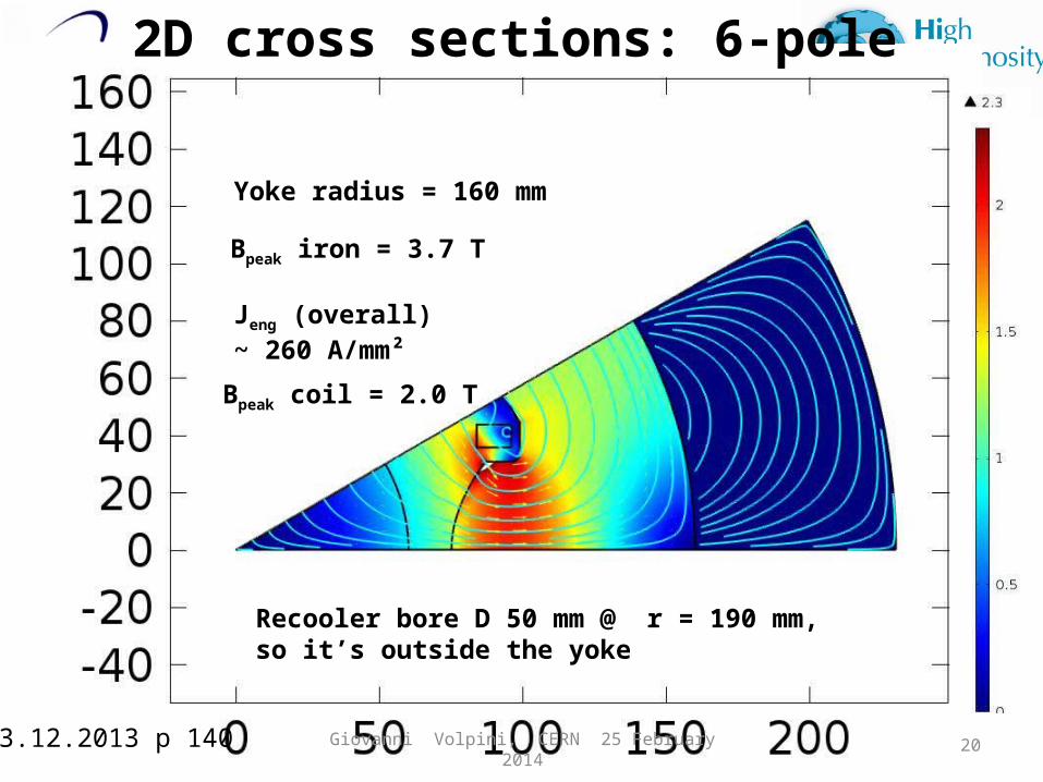
2D cross sections: 6-pole
Yoke radius = 160 mm
Recooler bore D 50 mm @ r = 190 mm, so it’s outside the yoke
Jeng (overall) ~ 260 A/mm²
Bpeak iron = 3.7 T
Bpeak coil = 2.0 T
03.12.2013 p 140

Giovanni Volpini, CERN 25 February 2014 21
100 200 300 400C urrent A
1
2
3
4F lux dens ity T
6- and 12-pole load lines
Bpeak on coil
B @ r=50mm
Design current = 150 A
4.22 K
Ic 179 A @ 5 T, 4.22 KSextupole
Dodecapole
1.9 K
Sextupole
Dodecapole