Hitachi Unified Storage VM Best Practices Guide for … HNAS practices outlined in this document...
15
MK-92HNAS026-01 Hitachi Unified Storage VM Best Practices Guide for HNAS Solutions By Francisco Salinas (Global Solution Services)
Transcript of Hitachi Unified Storage VM Best Practices Guide for … HNAS practices outlined in this document...
MK-92HNAS026-01
Hitachi Unified Storage VM Best Practices Guide
for HNAS Solutions
By Francisco Salinas (Global Solution Services)
MK-92HNAS026-01
Notices and Disclaimer Copyright © 2014 Hitachi Data Systems Corporation. All rights reserved.
The performance data contained herein was obtained in a controlled isolated environment. Actual results that
may be obtained in other operating environments may vary significantly. While Hitachi Data Systems
Corporation has reviewed each item for accuracy in a specific situation, there is no guarantee that the same
results can be obtained elsewhere.
All designs, specifications, statements, information and recommendations (collectively, "designs") in this
manual are presented "AS IS," with all faults. Hitachi Data Systems Corporation and its suppliers disclaim all
warranties, including without limitation, the warranty of merchantability, fitness for a particular purpose and
non-infringement or arising from a course of dealing, usage or trade practice. In no event shall Hitachi Data
Systems Corporation or its suppliers be liable for any indirect, special, consequential or incidental damages,
including without limitation, lost profit or loss or damage to data arising out of the use or inability to use the
designs, even if Hitachi Data Systems Corporation or its suppliers have been advised of the possibility of such
damages.
This document has been reviewed for accuracy as of the date of initial publication. Hitachi Data Systems
Corporation may make improvements and/or changes in product and/or programs at any time without notice.
No part of this document may be reproduced or transmitted without written approval from Hitachi Data
Systems Corporation.

MK-92HNAS026-01
Document Revision Level
Revision Date Description
MK-92HNAS026-00 March 2013 First publication
MK-92HNAS026-01 May 2014 Revision 1, replaces and supersedes
MK-92HNAS026-00.
Reference HUS VM Architecture Guide
Contributors The information included in this document represents the expertise, feedback, and suggestions of a
number of skilled practitioners. The author would like to recognize and sincerely thank the following
contributors and reviewers of this document (listed alphabetically):
Al Hagopian
Gokula Rangarajan
Phil Wood
Table of Contents
Intended audience ................................................................................................................................................................ 5
Overview ............................................................................................................................................................................... 5
HUS VM series configuration best practices ..................................................................................................................... 5
General Recommendations for HUS VM systems ........................................................................................ 5
Other Recommendations ............................................................................................................................... 6
Multi-LUN RAID groups ............................................................................................................................................ 6
Universal Volume Manager best practices ......................................................................................................................... 6
General recommendations ............................................................................................................................ 6
Virtualizing AMS/HUS 1x0 behind HUS VM .................................................................................................. 7
Avoiding LDEV carving of UVM external LUNs ............................................................................................. 8
eLUN size restrictions .................................................................................................................................... 8
Hitachi Dynamic Provisioning and UVM ........................................................................................................ 8
Recommendations for creating multiple LUs per AMS 2000 or HUS 1x0 RAID group ............................................. 9
LUN Mapping and Pathing Recommendations ............................................................................................. 9
Port I/O request limit ...................................................................................................................................... 9
Preferred Pathing ..................................................................................................................................................... 9
Path Redundancy ..................................................................................................................................................... 9
Direct-attach and switch-attach connectivity best practices ......................................................................................... 10
Two node cluster, direct-attached ................................................................................................................ 11
Two node cluster, switch-attached .............................................................................................................. 12
Virtualizing an AMS 2500 Rev. 01 behind a HUS VM system .......................................................................................... 13
5
Intended audience The intended audience for these guides is customers, authorized service providers, and Hitachi
Data Systems (HDS) personnel.
Overview The Hitachi Unified Storage VM (HUS VM) storage systems can be configured in numerous
ways. When attaching a Hitachi Network Attached Storage (HNAS) system to these systems, one
cannot treat the HNAS system like other typical SAN clients. The HNAS system is capable of
heavily driving a storage array and disks. The HNAS practices outlined in this document describe
how to configure the HNAS system to achieve the best results. Consult the HNAS Configuration
Guidelines document for additional information about HNAS practices.
HUS VM series configuration best practices
General Recommendations for HUS VM systems
Use a HNAS superflush setting of 3x128 for each HUS VM System Drive (SD) regardless
whether the drive is internal or external. HNAS supports larger superflush settings; however,
only use these settings when instructed by HDS Global Solutions and Services (GSS).
Use a RAID group size of 7D+1P for SAS with sequential workloads and 3D+1P for random
workloads to achieve optimal performance.
GSS strongly recommends that you attempt to configure one LDEV/logical unit (LU) per RAID/parity group when possible.
Configure any 7.2K RPM HDDs in RAID-6
Dedicate the RAID/parity groups to HNAS for optimal performance.
Set the HUS VM host mode to standard (default) for HNAS host groups.
Avoid sharing the following resources with any other non-HNAS clients for optimal
performance:
Hitachi Adaptable Modular Storage (AMS)\HUS 1x0 FC ports (when connected via Universal Volume Manager (UVM) system).
HUS VM FC or UVM ports.
RAID/parity groups or Hitachi Dynamic Provisioning (HDP) or Hitachi Dynamic Tiering (HDT) pools from either internal or external storage.
When using Hitachi Dynamic Provisioning or Hitachi Dynamic Tiering, set SOM 917 on (when
available). SOM 917 ensures that the pool/tier is rebalanced across the Parity Groups rather
than the pool volumes (LDEVs).
When using Hitachi Dynamic Provisioning or Hitachi Dynamic Tiering, the number of
Dynamic Provisioning Volumes (DP Vols) created should not exceed two (2) times the
number of RAID groups that are used in the underlying pool. For example, if an HDP or HDT
pool consists of LDEVs from four (4) RAID Groups, no more than 8 DP Vols should be
created and allocated to HNAS.
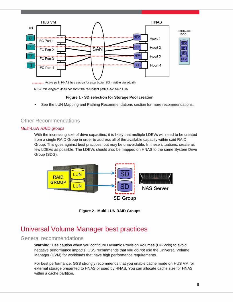
When creating storage pools on HNAS, make sure to select System Drives (SD’s) whose
paths are balanced across HNAS Hports and HUS VM FC ports for optimal performance.
See Figure 1.
6
Figure 1 - SD selection for Storage Pool creation
See the LUN Mapping and Pathing Recommendations section for more recommendations.
Other Recommendations
Multi-LUN RAID groups
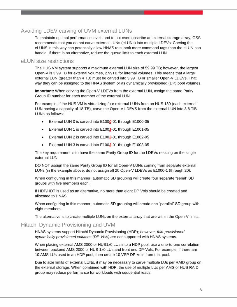
With the increasing size of drive capacities, it is likely that multiple LDEVs will need to be created
from a single RAID Group in order to address all of the available capacity within said RAID
Group. This goes against best practices, but may be unavoidable. In these situations, create as
few LDEVs as possible. The LDEVs should also be mapped on HNAS to the same System Drive
Group (SDG).
Figure 2 - Multi-LUN RAID Groups
Universal Volume Manager best practices
General recommendations
Warning: Use caution when you configure Dynamic Provision Volumes (DP-Vols) to avoid
negative performance impacts. GSS recommends that you do not use the Universal Volume
Manager (UVM) for workloads that have high performance requirements.
For best performance, GSS strongly recommends that you enable cache mode on HUS VM for
external storage presented to HNAS or used by HNAS. You can allocate cache size for HNAS
within a cache partition.

7
Virtualizing AMS/HUS 1x0 behind HUS VM
Each Adaptable Modular Storage system/Hitachi Unified Storage system (AMS\HUS) FC port has
an I/O request limit (queue depth) of 512 requests. Note that new HUS 0935A microcode can be
configured to support 1024 requests when using HNAS code 11.2.33.xx or higher. This setting
allows for 16 active LUNs on a FC port, with each LUN having a queue depth of 32. In UVM
mode, the maximum per port HUS VM I/O request limit is 384. In that scenario, GSS
recommends that you use 24 LUNs per port, with 12 being active LUNs and 12 being failover
LUNs. Use two paths, one from each controller. For the best performance, do not configure more
than two paths per LUN. See the configuration example in Figure 3 - External LUN Port Mapping.
Notes:
The HUS VM system assigns a queue limit value of eight to each external LUN. You can
modify the external LUN queue limit to be from two to 128. GSS recommends that you set the
queue limit value so that the total for all paths to that LU is 32.
Important: The Hitachi Unified Storage Volume Manager User’s Guide and the Universal
Volume Manager User’s Guide recommend that you limit to 500 tags the maximum number
of command tags going to an individual AMS or HUS for the best performance. See also the
section called Virtualizing an AMS 2500 Rev. 01 behind a HUS VM system for more settings.
In an environment that has no strict performance requirements, you can use more than 16 active
LUNs from an external AMS/HUS 1x0 port pair. In that scenario, you can reduce the total queue
limit to 16 or less for each of the external LUNs.
Figure 3 - External LUN Port Mapping
8
Avoiding LDEV carving of UVM external LUNs
To maintain optimal performance levels and to not oversubscribe an external storage array, GSS
recommends that you do not carve external LUNs (eLUNs) into multiple LDEVs. Carving the
eLUNS in this way can potentially allow HNAS to submit more command tags than the eLUN can
handle. If there is no alternative, reduce the queue limit to each external LUN.
eLUN size restrictions
The HUS VM system supports a maximum external LUN size of 59.99 TB; however, the largest
Open-V is 3.99 TB for external volumes, 2.99TB for internal volumes. This means that a large
external LUN (greater than 4 TB) must be carved into 3.99 TB or smaller Open-V LDEVs. That
way they can be assigned to the HNAS system or as dynamically provisioned (DP) pool volumes.
Important: When carving the Open-V LDEVs from the external LUN, assign the same Parity
Group ID number for each member of the external LUN.
For example, if the HUS VM is virtualizing four external LUNs from an HUS 130 (each external
LUN having a capacity of 18 TB), carve the Open-V LDEVS from the external LUN into 3.6 TiB
LUNs as follows:
External LUN 0 is carved into E1000-01 through E1000-05
External LUN 1 is carved into E1001-01 through E1001-05
External LUN 2 is carved into E1002-01 through E1002-05
External LUN 3 is carved into E1003-01 through E1003-05
The key requirement is to have the same Parity Group ID for the LDEVs residing on the single
external LUN.
DO NOT assign the same Parity Group ID for all Open-V LUNs coming from separate external
LUNs (in the example above, do not assign all 20 Open-V LDEVs as E1000-1 (through 20).
When configuring in this manner, automatic SD grouping will create four separate “serial” SD
groups with five members each.
If HDP/HDT is used as an alternative, no more than eight DP Vols should be created and
allocated to HNAS.
When configuring in this manner, automatic SD grouping will create one “parallel” SD group with
eight members.
The alternative is to create multiple LUNs on the external array that are within the Open-V limits.
Hitachi Dynamic Provisioning and UVM
HNAS systems support Hitachi Dynamic Provisioning (HDP); however, thin-provisioned
dynamically provisioned volumes (DP-Vols) are not supported with HNAS systems.
When placing external AMS 2000 or HUS1x0 LUs into a HDP pool, use a one-to-one correlation
between backend AMS 2000 or HUS 1x0 LUs and front end DP-Vols. For example, if there are
10 AMS LUs used in an HDP pool, then create 10 VSP DP-Vols from that pool.
Due to size limits of external LUNs, it may be necessary to carve multiple LUs per RAID group on
the external storage. When combined with HDP, the use of multiple LUs per AMS or HUS RAID
group may reduce performance for workloads with sequential reads.

9
Recommendations for creating multiple LUs per AMS 2000 or HUS 1x0 RAID group
For high performance sequential read workloads, the use of HDP or virtualization (UVM) may
cause reduced system performance.
You must dedicate all LUs created from a RAID group to the same HDP pool. You must
allocate to the HNAS system all DP-Vols created from that HDP pool. That means that you
do not share any resources that are associated with the HNAS system.
When creating DP-Vols, use a ratio of one DP-Vol to one AMS/HUS 1x0 external RAID group
to prevent oversubscription of the external array.
Example: There are 10x 8D+2P 2 TB RAID groups on a HUS 1x0. To use UVM, four LUs are
carved from each RAID group. All of the eLUNs are placed into a single HDP pool on a HUS
VM system. Because there are 10 RAID groups, GSS recommends that you create 10 DP-
Vols.
Be aware of the following LUN size limits: HUS VM system maximum internal LUN size is
3.99 TB, 60 TB using HDP, and 4 TB if using HDP with any Hitachi replication products,
including ShadowImage, TrueCopy, and Hitachi Universal Replication.
Note: The LUN size limits apply to SyncDR (Metro Cluster) implementations as well because
TrueCopy Synchronous is used.
LUN Mapping and Pathing Recommendations
Port I/O request limit
The HUS VM FC ports are designed to attach to multiple Fibre Channel (FC) clients. Each FC
port on a HUS VM has an I/O Request Limit (IORL) of 2048 requests. HNAS assumes that there
are no other clients connected to the same FC ports to which it is attached. For this reason, it is
best that HNAS have dedicated FC ports. If FC ports cannot be dedicated, you will need to keep
track of the number of LUNs mapped to other hosts and the queue depth for each of those LUNs
to ensure that the total number of requests from HNAS and other hosts does not exceed the port
IORL.
HNAS enforces a limit of 2000 requests per HUS VM FC port. HNAS assigns a queue depth of 32
for each HUS VM System Drive. Queue depth indicates the number of requests a particular LUN
can have outstanding. The recommendation is to have no more than 64 active LUNs presented to
an HNAS system through the same FC port. For example, if 128 LUNs are mapped to HNAS, the
minimum number of HUS VM FC ports required would be two (2). All 128 LUNs would be
mapped to both FC ports; however, only 64 LUNs would be actively receiving requests. The other
inactive LUNs would be available for path failover. HNAS will automatically balance the number of
LUNs it accesses from its own FC ports and the FC ports of the HUS VM. To determine the
minimum number of FC ports required to maintain System Drive queue depth, use the following
formula:
Number of FC ports = total number of LUNs / 64.
If the result is less than one, then add one for redundancy.
Preferred Pathing
Setting the preferred path is generally not required for the HUS VM system. HNAS automatically
manages the paths.
Note: HNAS only submits request through one path, all other paths are passive.
Path Redundancy
While only two FC paths are required per SD, assuming redundant SAN switches to achieve
redundancy, some may find it easier to map LUNs to all HUS VM FC ports that are connected to
10
HNAS. The best practice is to have enough paths so there is redundancy for each SD while
keeping the total number of logical paths under sixteen (16).
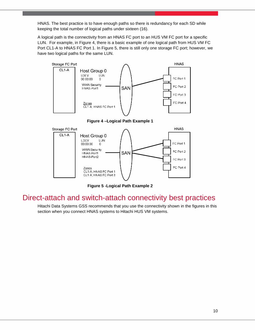
A logical path is the connectivity from an HNAS FC port to an HUS VM FC port for a specific
LUN. For example, in Figure 4, there is a basic example of one logical path from HUS VM FC
Port CL1-A to HNAS FC Port 1. In Figure 5, there is still only one storage FC port; however, we
have two logical paths for the same LUN.
Figure 4 –Logical Path Example 1
Figure 5 -Logical Path Example 2
Direct-attach and switch-attach connectivity best practices Hitachi Data Systems GSS recommends that you use the connectivity shown in the figures in this
section when you connect HNAS systems to Hitachi HUS VM systems.

11
Two node cluster, direct-attached
Figure 6 - Connectivity for a two node cluster, direct-attached configuration
The direct-attached connectivity for HUS VM differs from that of the USP/VSP system. The HNAS engineering team has modified the HNAS code to support the HUS VM system architecture.
Table 1 – Connectivity
Node ports: storage port Node ports: storage port
Node 1 hport 1: 1A Node 2 hport 1: 5A
Node 1 hport 2: 3A Node 2 hport 2: 7A
Node 1 hport 3: 2A Node 2 hport 3: 6A
Node 1 hport 4: 4A Node 2 hport 4: 8A
The HUS VM system does not support the HNAS 2000, 3100, and 3200 servers.

12
Two node cluster, switch-attached
Figure 7 - Connectivity for a two node cluster, switch-attached configuration
Table 2 – Zoning – Both nodes must see the exact same storage ports
Zone Node ports HUS VM ports
Zone 1 Node 1 hport 1 1A, 2A, 3A, 4A
Zone 2 Node 1 hport 2 1A, 2A, 3A, 4A
Zone 3 Node 1 hport 3 5A, 6A, 7A, 8A
Zone 4 Node 1 hport 4 5A, 6A, 7A, 8A
Zone 5 Node 2 hport 1 1A, 2A, 3A, 4A
Zone 6 Node 2 hport 2 1A, 2A, 3A, 4A
Zone 7 Node 2 hport 3 5A, 6A, 7A, 8A
Zone 8 Node 2 hport 4 5A, 6A, 7A, 8A

13
It is not necessary to create multiple host storage domains for each HNAS hport on a specific
HUS VM FC port. A single host storage domain is sufficient with multiple WWNs.
Figure 8 shows an HUS VM with 4 Channel Boards, in general spread out connectivity across Channel Boards. Configurations may be different if remote replication or virtualization is used.
Figure 8 - Connectivity for a two node cluster, switch-attached configuration
Virtualizing an AMS 2500 Rev. 01 behind a HUS VM system
If an AMS 2500 is externally connected to a HUS VM system, you must specify the CPU load
reduction for Cross-CTL I/O Mode port option.
The Cross-CTL I/O mode applies when using UVM system feature with an AMS 2500 system
with firmware 0890H or later. When using a UVM system with an AMS 2500 system, the HUS
VM system uses a round-robin approach for the I/Os to the AMS 2500 system. In a dual-core
AMS 2500 system, the effect is that half of the target LUs being handled by a core that does
not own the LU. This scenario results in higher CPU utilization. When you enable the mode,
the processing order between cores is tuned, which results in a lower CPU load.
The Cross-CTL I/O Mode port option applies to the Rev. 01 controllers but not to the Rev. 02
controllers because of the hardware architecture. As of firmware level 0893/B, the CPU load
reduction for Cross-Ctl I/O Mode is guarded from Rev. 02 controllers; therefore, with Rev. 02
controllers, this selection is not visible for the port options. This option is supported by the
following statement from the 0893/B ECN. 12) CPU Load Reduction for Cross-CTL I/O Mode
guard for DF800EH– Severity Low. Prior to level 0893/B and starting at 0890/B, the CPU load
reduction option was selectable for Rev2 controllers, but if it was turned on it could block the
controller.

14
If the AMS 2500 system is already connected and does not have this option set, setting the
option is a disruptive procedure. If multiple paths are connected, it is a minor disruption
because you can remove one path and then add the path again with the correct option
selected while the remaining paths stay connected.

Hitachi Data Systems
Corporate Headquarters
2845 Lafayette Street Santa Clara, California 95050-2639 U.S.A. www.hds.com
Regional Contact Information
Americas +1 408 970 1000 [email protected]
Europe, Middle East, and Africa
+44 (0) 1753 618000 [email protected]
Asia Pacific
+852 3189 7900
MK-92HNAS026-01