HiSwitch 2
112
Power Quality Systems Liebert HiSwitch2 Digital Static Transfer Switch 100 to 1000 A - 50/60 Hz Installation and User Manual EN
-
Upload
brightstardust -
Category
Documents
-
view
215 -
download
0
Transcript of HiSwitch 2

8/11/2019 HiSwitch 2
http://slidepdf.com/reader/full/hiswitch-2 1/112
Power Quality Systems
Liebert HiSwitch2
Digital Static Transfer Switch
100 to 1000 A - 50/60 Hz
Installation and User ManualEN

8/11/2019 HiSwitch 2
http://slidepdf.com/reader/full/hiswitch-2 2/112
8/11/2019 HiSwitch 2
http://slidepdf.com/reader/full/hiswitch-2 3/112
(11/04)
Dear Customer,
thank you for choosing a Liebert product.
If this is your first purchase, we’d like to welcome you to the world of Liebert.
We’re looking forward to working with you in the future and providing you with all the post-sales service you
need to get the most out of your Liebert HiSwitch2.
If you already own and use other Liebert products, we’re happy that you continue to prefer Liebert.
We’re constantly working with you to ensure the success of your business.
Our philosophy is summed up in our motto, “Keeping Business in Business”.
We’d welcome your advice on how we can improve our work on our mission.
EMERSON NETWORK POWER

8/11/2019 HiSwitch 2
http://slidepdf.com/reader/full/hiswitch-2 4/112
Static Transfer Switch Liebert HiSwitch2 User’s Manual
Page iv (11/04)

8/11/2019 HiSwitch 2
http://slidepdf.com/reader/full/hiswitch-2 5/112
User’s Manual Liebert HiSwitch2 Static Transfer Switch
(11/04) Page v
This manual describes installation and operating procedures for static transfer switches (HiSwitch2).
Read all sections of the manual carefully before beginning installation.
HiSwitch2 commissioning and technical assistance must be performed
by a technician trained and authorised by the manufacture (or distributor).
Failure to comply with this requirement poses a risk to the safety of personnel
and the functioning of the system and will render all guarantees invalid.
HiSwitch2 is designed exclusively for Commercial/Industrial applications,
and may not be used with vital support systems of any kind.
WARNING:
This is a product for restricted sales distribution to informed partners.
Installation restrictions or additional measures may be needed to prevent disturbance.
(See EN 50091-2)
If you encounter any problems with the procedures contained in this manual
you should seek immediate assistance from the Liebert Sales Office
from whom the equipment was purchased.
Alternatively, contact the Liebert's Customer Service & Support department
at the address shown below:
Liebert HIROSS Services (HQ)
Customer Service and Support Department
Via Leonardo da Vinci 8
35028 - Piove di Sacco (PD)
Italy
Help Desk Telephone +39 049 9719311
Fax +39 049 9719053
Emerson Network Power Ltd - United Kingdom
Customer Service and Support Department
Globe Park
Marlow
Buckinghamshire SL71YG
United Kingdom
Telephone +44 1628 40 32 00Fax +44 1628 40 32 03
Please visit our web site: http://ups.liebert-hiross.com/
While every precaution has been taken to ensure accuracy and comleteness in this manual, Liebert Corporation
assumes no responsibility and disclaims all liability for damages resulting from use of this information or for
any errors or omissions.
Liebert Corporation pursues a policy of continual product development and reserves the right to change the
equipment design without notice.
Copyright 2004 by Liebert Corporation.
Unauthorized reproduction prohibited All rights reserved.

8/11/2019 HiSwitch 2
http://slidepdf.com/reader/full/hiswitch-2 6/112
Static Transfer Switch Liebert HiSwitch2 User’s Manual
Page vi (11/04)
This manual describes the following equipment:
EQUIPMENT ITEM CODE
100 A HiSwitch2 5230031B
250 A HiSwitch2 5230032C
400 A HiSwitch2 5230033D
600 A HiSwitch2 5230034E
800 A HiSwitch2 5230035F
1000 A HiSwitch2 5230036G
Led display panel with keylockout switch (for 100÷1000A) 22-806165-01
OPTIONS
LCD touch screen display with keylockout switch (for 100÷1000A) 22-806139-00
Remote Source Selection Board STSRSS
Network Interface Card (NIC) STSNIC
Input Contact Isolator (ICI) Board STSICI
Programmable Relay Board (PRB) STSPRB
Comms Board w/SiteScan and Modem Interface STSCOM
Safety instructions
The warning triangle identifies instructions which are essential to ensuring the user’s safety
Follow these instructions scrupulously to prevent serious injury
8/11/2019 HiSwitch 2
http://slidepdf.com/reader/full/hiswitch-2 7/112
User’s Manual Liebert HiSwitch2 Static Transfer Switch
(11/04) Page vii
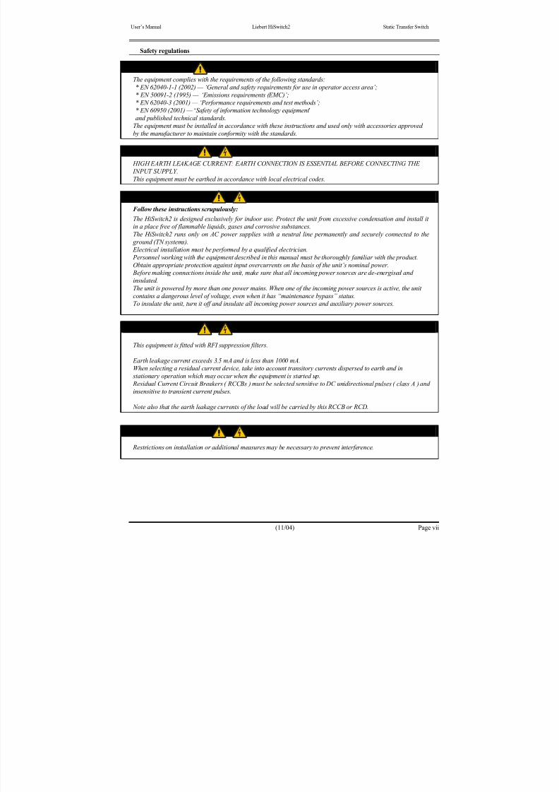
Safety regulations
CONFORMITY WITH STANDARDS
The equipment complies with the requirements of the following standards:
* EN 62040-1-1 (2002) — ‘General and safety requirements for use in operator access area’;
* EN 50091-2 (1995) — ‘Emissions requirements (EMC)’;* EN 62040-3 (2001) — ‘Performance requirements and test methods’;
* EN 60950 (2001) — ‘Safety of information technology equipment ’
and published technical standards.
The equipment must be installed in accordance with these instructions and used only with accessories approved
by the manufacturer to maintain conformity with the standards.
WARNING
HIGH EARTH LEAKAGE CURRENT : EARTH CONNECTION IS ESSENTIAL BEFORE CONNECTING THE
INPUT SUPPLY.
This equipment must be earthed in accordance with local electrical codes.
WARNING
Follow these instructions scrupulously:
The HiSwitch2 is designed exclusively for indoor use. Protect the unit from excessive condensation and install it
in a place free of flammable liquids, gases and corrosive substances.
The HiSwitch2 runs only on AC power supplies with a neutral line permanently and securely connected to the
ground (TN systems).
Electrical installation must be performed by a qualified electrician.
Personnel working with the equipment described in this manual must be thoroughly familiar with the product.
Obtain appropriate protection against input overcurrents on the basis of the unit’s nominal power.
Before making connections inside the unit, make sure that all incoming power sources are de-energised and
insulated.
The unit is powered by more than one power mains. When one of the incoming power sources is active, the unit
contains a dangerous level of voltage, even when it has “maintenance bypass” status.To insulate the unit, turn it off and insulate all incoming power sources and auxiliary power sources.
Caution
This equipment is fitted with RFI suppression filters.
Earth leakage current exceeds 3.5 mA and is less than 1000 mA.
When selecting a residual current device, take into account transitory currents dispersed to earth and in
stationary operation which may occur when the equipment is started up.
Residual Current Circuit Breakers ( RCCBs ) must be selected sensitive to DC unidirectional pulses ( class A ) and
insensitive to transient current pulses.
Note also that the earth leakage currents of the load will be carried by this RCCB or RCD.
Important
Restrictions on installation or additional measures may be necessary to prevent interference.

8/11/2019 HiSwitch 2
http://slidepdf.com/reader/full/hiswitch-2 8/112
Static Transfer Switch Liebert HiSwitch2 User’s Manual
Page viii (11/04)
General
Like all high voltage equipment, the HiSwitch2 contains hazardous voltage. The risk of contact with this voltage is
minimised as components under voltage are housed behind a hinged door which may be locked. Additional
internal safety shields protect devices in accordance with IP20 standards.
There is no risk for personnel working on the equipment during regular operation in compliance with therecommended operating procedures.
All assistance and maintenance procedures requiring access to the inside of the equipment must be carried out
exclusively by trained personnel.
WARNING
HiSwitch2 DOES NOT INCORPORATE AUTOMATIC PROTECTION AGAINST VOLTAGE RETURNING TO
THE INPUT; PRIMARY POWER KNIFE SWITCHES OUTSIDE THE SYSTEM MUST BE LABELLED TO
WARN SERVICE PERSONNEL THAT THE CIRCUIT IS CONNECTED TO THE STATIC TRANSFER SWITCH
SYSTEM (STS).
The wording must be similar to the following:
ISOLATE THE STATIC TRANSFER SWITCH
(STS) BEFORE
WORKING ON THIS CIRCUIT
Important
Support Information:If you require assistance for any reason, please have the following information available:
Model and size
Part number
Serial number
Date installed
Location
Voltage & Frequency

8/11/2019 HiSwitch 2
http://slidepdf.com/reader/full/hiswitch-2 9/112
User’s Manual Liebert HiSwitch2 Static Transfer Switch
(11/04) Page ix
Contents
Part I Installation Manual........................................................................ 1-1
1 Chapter 1 – Installation Procedure...................................................................................................................... 1-1
1.1 Introduction ......................................................................................................................................................... 1-11.2 Environmental considerations............................................................................................................................. 1-2
1.2.1 Location of the HiSwitch2............................................................................................................................... 1-2
1.2.2 Heat Output ...................................................................................................................................................... 1-2
1.2.3 Cooling ............................................................................................................................................................. 1-2
1.3 Mechanical Considerations................................................................................................................................. 1-3
1.3.1 System Components......................................................................................................................................... 1-3
1.3.2 Frame and Enclosure........................................................................................................................................ 1-3
1.3.3 Moving the cabinets ......................................................................................................................................... 1-3
1.3.4 Clearances ........................................................................................................................................................ 1-3
1.3.5 Placing it in the operative position................................................................................................................... 1-3
1.3.6 Leveling and anchoring the unit to the floor ................................................................................................... 1-4
1.3.7 Cable entry ....................................................................................................................................................... 1-4
1.3.8 Access............................................................................................................................................................... 1-4
1.4 Preliminary Controls ........................................................................................................................................... 1-4
1.4.1 Identification .................................................................................................................................................... 1-4
2 Chapter 2 - Installation (Electrical)..................................................................................................................... 2-1
2.1 Power cabling...................................................................................................................................................... 2-1
2.1.1 Cable size.......................................................................................................................................................... 2-1
2.1.2 Table for determining cable size...................................................................................................................... 2-2
2.1.3 General Notes................................................................................................................................................... 2-2
2.1.4 Cable connections ............................................................................................................................................ 2-2
2.1.5 Safety earth....................................................................................................................................................... 2-2
2.1.6 Protective devices............................................................................................................................................. 2-3
2.1.7 Wiring procedure ............................................................................................................................................. 2-4
2.2 Distance from floor to connection point on the equipment:............................................................................... 2-52.3 Auxiliary connections ......................................................................................................................................... 2-6
2.3.1 Introduction ...................................................................................................................................................... 2-6
2.3.2 Auxiliary terminal block X1 ............................................................................................................................ 2-6
2.3.3 Emergency stop................................................................................................................................................ 2-7
2.3.4 Power supply.................................................................................................................................................... 2-8
3 Chapter 3 – Optional equipment – Installation notes ......................................................................................... 3-1
3.1.1 Introduction ...................................................................................................................................................... 3-1
3.1.2 Remote Source Selection ................................................................................................................................. 3-1
3.1.3 Key Lockout Switch......................................................................................................................................... 3-2
3.1.4 Redundant Output Breaker .............................................................................................................................. 3-2
3.1.5 Seismic Floor Anchors..................................................................................................................................... 3-2
3.1.6 Programmable Relay Board............................................................................................................................. 3-33.1.7 Input Contact Isolator Board............................................................................................................................ 3-4
3.1.8 Comms Board................................................................................................................................................... 3-5
4 Chapter 4 – Communication System.................................................................................................................. 4-1
4.1 Introduction ......................................................................................................................................................... 4-1
4.2 RS-232 Port......................................................................................................................................................... 4-2
4.2.1 Terminal Port Connections .............................................................................................................................. 4-2
4.2.2 Connecting and Using a Terminal ................................................................................................................... 4-3
4.2.3 Configuring the HiSwitch2 via the Terminal .................................................................................................. 4-4
4.2.4 Setting Event Masks with the Terminal........................................................................................................... 4-9
4.3 Communications options .................................................................................................................................. 4-10
4.3.1 Internal modem .............................................................................................................................................. 4-10
4.3.2 Network Interface Card (NIC)....................................................................................................................... 4-114.3.3 Input Contact Isolator (ICI) Board................................................................................................................. 4-11
4.3.4 Programmable Relay Board (PRB) ............................................................................................................... 4-11
4.3.5 Comms Board................................................................................................................................................. 4-11
8/11/2019 HiSwitch 2
http://slidepdf.com/reader/full/hiswitch-2 10/112
Static Transfer Switch Liebert HiSwitch2 User’s Manual
Page x (11/04)
5 Chapter 5 – Technical Specifications ................................................................................................................. 5-1
5.1 Conformity and Standards .................................................................................................................................. 5-1
5.2 Environmental Conditions .................................................................................................................................. 5-1
5.3 Mechanical characteristics .................................................................................................................................. 5-2
5.4 Electrical Characteristics (Inputs)....................................................................................................................... 5-3
5.5 Electrical Characteristics (Output)...................................................................................................................... 5-3
5.6 General characteristics ........................................................................................................................................ 5-4
6 Chapter 6 – Installation drawings ....................................................................................................................... 6-1
6.1 Introduction ......................................................................................................................................................... 6-1
6.1.1 HiSwitch2 100 &250 A – general view ......................................................................................................... 6-2
6.1.2 HiSwitch2 100 &250 A – View of cable connections and mechanical details of their terminal bars ......... 6-3
6.1.3 HiSwitch2 400 &600 A – general view ......................................................................................................... 6-4
6.1.4 HiSwitch2 400 &600 A – View of cable connections and mechanical details of their terminal bars ......... 6-5
6.1.5 HiSwitch2 800 &1000 A – general view ....................................................................................................... 6-6
6.1.6 HiSwitch2 800 &1000 A – View of cable connections and mechanical details of their terminal bars ....... 6-7
6.1.7 HiSwitch2 100 ÷ 1000 A – Auxiliary terminal blocks (X1) details for all units........................................... 6-8
6.1.8 Typical options location................................................................................................................................... 6-9
6.1.9 Electrical connections in the HiSwitch2........................................................................................................ 6-10
6.1.10 Location of keys in HiSwitch2 power switch locks.................................................................................... 6-11
Part II User’s Manual .............................................................................. 7-1
7 Chapter 7 – General Description ........................................................................................................................ 7-1
7.1 Introduction ......................................................................................................................................................... 7-1
7.1.1 System Description .......................................................................................................................................... 7-1
7.1.2 HiSwitch2 Static Transfer Switch.................................................................................................................... 7-2
7.1.3 Source Transfer ................................................................................................................................................ 7-2
7.1.4 Automatic Transfer/Retransfer ........................................................................................................................ 7-2
7.1.5 Emergency Transfer......................................................................................................................................... 7-3
7.1.6 Load Current Transfer Inhibit.......................................................................................................................... 7-37.1.7 SCR Failure ...................................................................................................................................................... 7-3
7.1.8 On/Off Sequence.............................................................................................................................................. 7-3
7.1.9 Redundancy...................................................................................................................................................... 7-3
7.1.10 Emergency stop button..................................................................................................................................... 7-3
7.2 Modes of Operation of the STS.......................................................................................................................... 7-4
7.2.1 Configuration of HiSwitch2 power isolators................................................................................................... 7-5
7.2.2 Typical HiSwitch2 configuration in a dual-bus power supply system ........................................................... 7-6
8 Chapter 8 – Operating the Led front panel......................................................................................................... 8-1
8.1 Introduction ......................................................................................................................................................... 8-1
8.2 LEDs and Buttons and Key Lockout Switch...................................................................................................... 8-1
8.2.1 Front Panel Controls ........................................................................................................................................ 8-1
8.2.2 Event Controls.................................................................................................................................................. 8-18.2.3 LED Definitions ............................................................................................................................................... 8-2
8.2.4 Button Definitions............................................................................................................................................ 8-3
8.2.5 Key Lockout Switch......................................................................................................................................... 8-4
9 Chapter 9 – Operating Procedures...................................................................................................................... 9-1
9.1 Introduction ......................................................................................................................................................... 9-1
9.1.1 General notes.................................................................................................................................................... 9-1
9.1.2 Power isolators ................................................................................................................................................. 9-1
9.2 Operating instructions ......................................................................................................................................... 9-2
9.2.1 Introduction ...................................................................................................................................................... 9-2
9.2.2 Normal System Turn-On.................................................................................................................................. 9-2
9.2.3 Manual Transfer / Preferred Source Selection (for LED Display panel)........................................................ 9-3
9.2.4 Manual Transfer / Preferred Source Selection for LCD touch screen display (Option) ................................ 9-49.2.5 Maintenance Bypass procedure ....................................................................................................................... 9-5
9.2.6 Normal System Shutdown ............................................................................................................................... 9-8

8/11/2019 HiSwitch 2
http://slidepdf.com/reader/full/hiswitch-2 11/112
User’s Manual Liebert HiSwitch2 Static Transfer Switch
(11/04) Page xi
10 Chapter 10 – Alarm and faults.......................................................................................................................... 10-1
10.1 Messages on the display panel.......................................................................................................................... 10-1
10.2 Event mask ........................................................................................................................................................ 10-1
10.3 Event and History Logs .................................................................................................................................... 10-2
10.3.1 Event Log ....................................................................................................................................................... 10-2
10.3.2 History Log .................................................................................................................................................... 10-2
10.4 Alarm Notes ...................................................................................................................................................... 10-210.5 List of Messages................................................................................................................................................ 10-3
11 Chapter 11 – Touch Screen Interface (Option) ................................................................................................ 11-1
11.1 Display Overview ............................................................................................................................................. 11-1
11.2 Menu Overview................................................................................................................................................. 11-2
11.3 Security.............................................................................................................................................................. 11-3
11.3.1 Using the Optional Key Lockout Switch....................................................................................................... 11-3
11.3.2 Using the Password........................................................................................................................................ 11-3
11.4 Mimic Display................................................................................................................................................... 11-3
11.5 Event Controls................................................................................................................................................... 11-4
11.6 Event Display .................................................................................................................................................... 11-4
11.7 Menu bar ........................................................................................................................................................... 11-4
11.8 Configuration Menu.......................................................................................................................................... 11-411.9 System Ratings.................................................................................................................................................. 11-4
11.10 Event Masks ................................................................................................................................................... 11-4
11.10.1 User Settings................................................................................................................................................... 11-5
11.10.2 Source Set Points............................................................................................................................................ 11-6
11.10.3 System Settings .............................................................................................................................................. 11-8
11.10.4 Comm Options ............................................................................................................................................... 11-8
11.10.5 Configuring the Modem................................................................................................................................. 11-8
11.10.6 Configuring Pager Support .......................................................................................................................... 11-10
11.10.7 Configuring the Input Contact Isolator (ICI) settings ................................................................................. 11-10
11.10.8 Configuring the Programmable Relay Board Settings ................................................................................ 11-11
11.10.9 Configuring the Network Interface Card..................................................................................................... 11-12
11.10.10 SiteScan Configuration.......................................................................................................................... 11-12
11.10.11 Saving Your Communications Configurations ..................................................................................... 11-1211.10.12 System Options ...................................................................................................................................... 11-13
11.10.13 Logs........................................................................................................................................................ 11-14
11.10.14 Source Transfers .................................................................................................................................... 11-15
11.10.15 Startup Procedure................................................................................................................................... 11-15
11.10.16 Bypass Procedure................................................................................................................................... 11-15
11.10.17 Help........................................................................................................................................................ 11-15
11.10.18 Logo ....................................................................................................................................................... 11-15
11.11 Cleaning the LCD Touch Screen................................................................................................................. 11-15
11.12 Operating instructions for the Touch Screen Interface ............................................................................... 11-15
11.13 EVENT MESSAGE HELP TEXT.............................................................................................................. 11-16
8/11/2019 HiSwitch 2
http://slidepdf.com/reader/full/hiswitch-2 12/112
Static Transfer Switch Liebert HiSwitch2 User’s Manual
Page xii (11/04)
Note
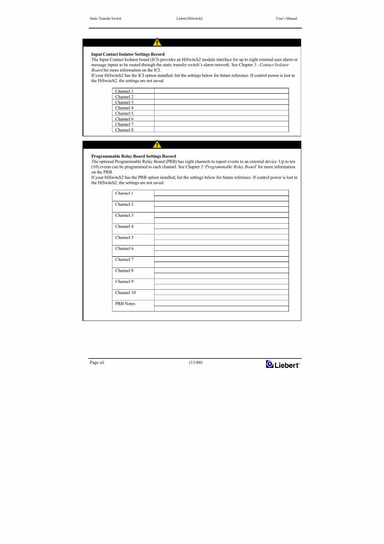
Input Contact Isolator Settings Record
The Input Contact Isolator board (ICI) provides an HiSwitch2 module interface for up to eight external user alarm or
message inputs to be routed through the static transfer switch’s alarm network. See Chapter 3 - Contact Isolator
Board for more information on the ICI.
If your HiSwitch2 has the ICI option installed, list the settings below for future reference. If control power is lost in
the HiSwitch2, the settings are not saved.
Note
Programmable Relay Board Settings Record
The optional Programmable Relay Board (PRB) has eight channels to report events to an external device. Up to ten
(10) events can be programmed to each channel. See Chapter 3 ‘ Programmable Relay Board ’ for more information
on the PRB.
If your HiSwitch2 has the PRB option installed, list the settings below for future reference. If control power is lost in
the HiSwitch2, the settings are not saved.
Channel 1
Channel 2
Channel 3
Channel 4
Channel 5
Channel 6
Channel 7
Channel 8
Channel 1
Channel 2
Channel 3
Channel 4
Channel 5
Channel 6
Channel 7
Channel 8
Channel 9
Channel 10
PRB Notes
8/11/2019 HiSwitch 2
http://slidepdf.com/reader/full/hiswitch-2 13/112
Installation Manual Chapter 1 - Installation Procedure
Static transfer switch Liebert HiSwitch2
(11/04) Page 1-1
Part I Installation Manual
1 Chapter 1 – Installation Procedure
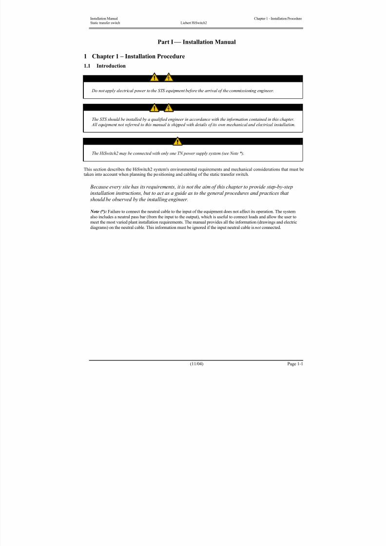
1.1 Introduction
WARNING
Do not apply electrical power to the STS equipment before the arrival of the commissioning engineer.
WARNING
The STS should be installed by a qualified engineer in accordance with the information contained in this chapter.
All equipment not referred to this manual is shipped with details of its own mechanical and electrical installation.
NOTE
The HiSwitch2 may be connected with only one TN power supply system (see Note *).
This section describes the HiSwitch2 system's environmental requirements and mechanical considerations that must betaken into account when planning the positioning and cabling of the static transfer switch.
Because every site has its requirements, it is not the aim of this chapter to provide step-by-step
installation instructions, but to act as a guide as to the general procedures and practices that
should be observed by the installing engineer.
Note (*): Failure to connect the neutral cable to the input of the equipment does not affect its operation. The system
also includes a neutral pass bar (from the input to the output), which is useful to connect loads and allow the user to
meet the most varied plant installation requirements. The manual provides all the information (drawings and electric
diagrams) on the neutral cable. This information must be ignored if the input neutral cable is not connected.
8/11/2019 HiSwitch 2
http://slidepdf.com/reader/full/hiswitch-2 14/112
Chapter 1 - Installation Procedure Installation Manual
Liebert HiSwitch2 Static transfer switch
Page 1-2 (11/04)
1.2 Environmental considerations
1.2.1 Location of the HiSwitch2
The HiSwitch2 is suitable for indoor use only.
The unit should be located in a cool, dry, clean-air environment with adequate ventilation to keep the ambient
temperature within the specified operating range (see Table 5-2).
All models in the HiSwitch2 range are cooled with the aid of internal fans and fitted with a system for monitoring
correct operation.
Cooling air enters the STS unit through the ventilation grids located at various points on the cabinet and is released
through the grids on the roof.
When the cabinet is located on a raised floor, bottom cable entry is used, additional cooling air also enters the
HiSwitch2 via the floor void. If necessary, an air conditioning system should be installed, and a suitable air filtration
system should be used if the HiSwitch2 is to operate in a dirty environment.
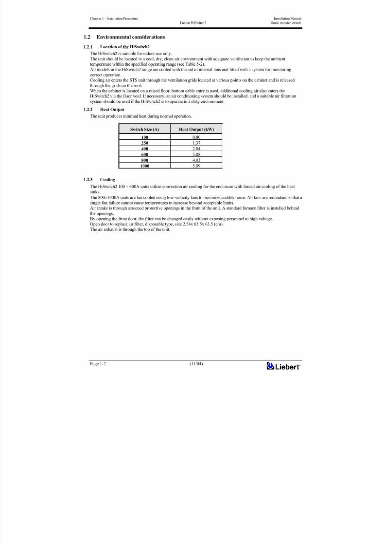
1.2.2 Heat Output
The unit produces minimal heat during normal operation.
Switch Size (A) Heat Output (kW)
100 0.80
250 1.37
400 2.04
600 3.08
800 4.03
1000 5.09
1.2.3 Cooling
The HiSwitch2 100 ÷ 600A units utilize convection air cooling for the enclosure with forced air cooling of the heat
sinks.
The 800÷1000A units are fan cooled using low-velocity fans to minimize audible noise. All fans are redundant so that a
single fan failure cannot cause temperatures to increase beyond acceptable limits.Air intake is through screened protective openings in the front of the unit. A standard furnace filter is installed behind
the openings.
By opening the front door, the filter can be changed easily without exposing personnel to high voltage.
Open door to replace air filter, disposable type, size 2.54x 63.5x 63.5 (cm).
The air exhaust is through the top of the unit.
8/11/2019 HiSwitch 2
http://slidepdf.com/reader/full/hiswitch-2 15/112
Installation Manual Chapter 1 - Installation Procedure
Static transfer switch Liebert HiSwitch2
(11/04) Page 1-3
1.3 Mechanical Considerations
1.3.1 System Components
All HiSwitch2 models provide two static transfer switches within one enclosure, with the ability to transfer between
two input sources to a single output.
All HiSwitch2s can be configured either a LCD touch screen display or a LED display for monitoring and configuring
the unit.
1.3.2 Frame and Enclosure
The complete HiSwitch2 is housed in a freestanding enclosure. The frame is constructed of galvanized steel and pops
riveted to provide a strong substructure. The cabinet is a NEMA type 1 enclosure and meets IP20 requirements. The
cabinet is structurally designed to handle lifting from the base.
The frame is designed to accommodate floor stands.
1.3.3 Moving the cabinets
The route to be travelled between the point of arrival and the unit’s position must be planned to make sure that all
passages are wide enough for the unit and that floors are capable of supporting its weight (for instance, check that
doorways, lifts, ramps, etc. are adequate and that there are no impassable corners or changes in the level of corridors).
WARNING
Ensure that any lifting equipment that used in moving the HiSwitch2 cabinet has sufficient lifting capacity before
use.
LOCATE THE CENTER OF GRAVITY SYMBOLS AND DETERMINE THE UNIT’S WEIGHT
BEFORE HANDLING THE CABINET.
Ensure that the floor of the room in which the equipment is to be installed has an adequate carrying capacity in Kg/cm2.
Check weights precisely using the Tables of Mechanical Characteristics in Chapter 5.3.
The unit can be moved by forklift or pallet jack. When moving the unit by forklift, lift the unit from the rear so as to
protect the front panel. Do not exceed a 15 degree tilt with the forklift.
Also, if you are moving the unit by forklift or pallet jack after it has been removed from the pallet, be aware of thelocation of the casters and leveling feet so as not to damage them.
Most HiSwitch2 models are contained in one cabinet. The 800–1000 amp units are contained in two cabinets that are
connected together and shipped on one pallet.
Because the weight distribution in the cabinet is uneven, use extreme care during handling and transporting.
1.3.4 Clearances
The HiSwitch2 has no ventilation grills at either side or at the rear, and so does not require clearances. Rear access is
not essential for maintenance work. Clearance around the front of the equipment should be sufficient to enable free
passage of personnel with the doors fully opened. It is important to leave a distance of at least 475 mm between the top
of the HiSwitch2 and the ceiling of the room in which it is installed to permit adequate circulation of air coming out of
the unit.
1.3.5 Placing it in the operative position
The unit is furnished with integral castors that allow the unit to be rolled into place after it has reached its location and
is removed from the pallet.
WARNING
Exercise extreme care when handling static switch cabinets to avoid equipment damage or injury to personnel.
If moving the unit up a ramp on its castors or a pallet jack, ensure that the incline does not exceed fifteen (15)
degrees.
After the unit has been inspected and no problems are found, the unit can be moved to its installation location.
When the equipment has been finally positioned ensure the adjustable feet are set so that the HiSwitch2 will remainstationary and stable (see Chapter 6).

8/11/2019 HiSwitch 2
http://slidepdf.com/reader/full/hiswitch-2 16/112
Chapter 1 - Installation Procedure Installation Manual
Liebert HiSwitch2 Static transfer switch
Page 1-4 (11/04)
1.3.6 Leveling and anchoring the unit to the floor
The frame includes heavy-duty swivel castors for ease of installation, plus permanent leveling feet for final installation.
The unit also can be fastened to the floor using optional seismic anchors to meet seismic Zone 4 requirements.
See ‘Installation drawings’ in Chapter 6 for instructions and details for installing seismic anchoring.
1.3.7 Cable entry
The unit is designed with top and bot tom cable terminations to allow maximum flexibility in its installation.
Cables can be installed through the top or bottom of the unit through removable conduits plates.
See ‘Installation drawings’ in Chapter 6.
Note When selecting the power cables for side entry to a module located on a solid floor, consideration
must be given to the minimum permissible bending radius of the proposed cables to ensure that
they can be fashioned to reach the HiSwitch2 connection bus-bars
1.3.8 Access
The HiSwitch2 is designed so all repairs and maintenance can be done from the front or top of the unit.All components that may need repair or replacement during routine field maintenance are safely accessed with the units
in bypass without removing power from the unit.
1.4 Preliminary Controls
Before you install the system hardware you should carry out the following preliminary checks:
1. Verify that the HiSwitch2 room satisfies the environmental conditions stipulated in the equipment
specifications, paying particular attention to the ambient temperature and air exchange system.
2. Remove any packaging debris, then visually examine the HiSwitch2 for damage in transit, both internally and
externally. Report any such damage to the shipper immediately.
3. Please make a note of the serial number and key type (engraved on both sides) of each power switch and keep it
with the installation documents. This information will be essential for replacing the keys if you lose them; if you
do not have the numbers, the locks will have to be replaced.
1.4.1 Identification
The HiSwitch2 has an identification tag on the back of the main door reporting the model and size. A metal disk
fastened to the inside top of the cabinet is engraved with its serial number.
Record the model numbers and serial numbers in the front of this installation manual. A record of this information is
necessary should servicing be required.
8/11/2019 HiSwitch 2
http://slidepdf.com/reader/full/hiswitch-2 17/112
Installation manual Chapter 2 – Installation (Electrical)
Static transfer switch Liebert HiSwitch2
(11/04) Page 2-1
2 Chapter 2 - Installation (Electrical)The HiSwitch2 requires both «power» and «control» cabling once it has been mechanically installed. All «control»
cables, whether screened or not, should be run separate from the power cables in metal conduits or metal ducts which
are electrically bonded to the metalwork of the cabinets to which they are connected.
Note: Auxiliary connections are needed to connect the coils of external circuit breakers and of AC power supply lines
to the logical cards in order to permit external action permitting complete insulation of the static transfer switch.
2.1 Power cabling
WARNING
BEFORE CABLING UP THE HiSwitch2 , ENSURE THAT YOU ARE AWARE OF THE LOCATION AND
OPERATION OF THE EXTERNAL SWITCHES THAT CONNECT THE HiSwitch2 INPUT/BYPASS SUPPLY
TO THE MAINS DISTRIBUTION PANEL.
CHECK THAT THESE SUPPLIES ARE ELECTRICALLY ISOLATED, AND POST ANY NECESSARY
WARNING SIGNS TO PREVENT THEIR INADVERTENT OPERATION.
The two input power feeds (sources) to the HiSwitch2 should be from two independent sources to avoid a common
source failure.
To ensure proper operation of the HiSwitch2, the two input sources must be the same nominal voltage level and phase
rotation.
For uninterrupted automatic transfer, the two input sources should be synchronized within 15 degrees.
CAUTION
THE INPUT SOURCES TO THE STATIC SWITCH MUST BE GROUNDED-WYE SOURCES. INPUT
SOURCES OTHER THAN SOLIDLY GROUNDED-WYE SOURCES MAY CAUSE DAMAGE TO
THE SWITCH.
The HiSwitch2 is designed for operation with 3 or 4-wire solidly grounded sources only.
For 4-wire operation, the common source neutral must be connected to the HiSwitch2.
4-Wire-Plus-Ground Systems — When 4-wire-plus-ground input feeds are utilized, the input power sources must be
properly grounded. Because the neutral is not switched by the HiSwitch2, the neutrals of the two power sources are
solidly interconnected.
Where possible, the two power sources should be located in close proximity and a single neutral-to-ground bond made.
For cable entry, refer to section 1.3.5.
2.1.1 Cable size
The principal factors influencing the choice of cables and cable sizes are voltage, current (taking over-current into
account), ambient temperature and the conditions of installation.
The size of system power cables must be determined in accordance with the following descriptions:
Input /output cables
The size of input/output cables must be determined by identifying the maximum input current in Table 2-1, in
accordance with size.
The size of input and output power cables depends on the device for protection from overcurrent upstream, in
accordance with local codes and other pertinent regulations.
Note: Correct cable size must also take into account the system’s overload capacity (see Chapter 5 – Technical
Specifications: - Electrical Characteristics).
8/11/2019 HiSwitch 2
http://slidepdf.com/reader/full/hiswitch-2 18/112
Chapter 2 – Installation (Electrical) Installation manual
Liebert HiSwitch2 Static transfer switch
Page 2-2 (11/04)
2.1.2 Table for determining cable size
Note: The table below gives nominal currents for determining the size of HiSwitch2 power cables. Other factors which
must be taken into consideration include cable route length, coordination with protective devices, etc.
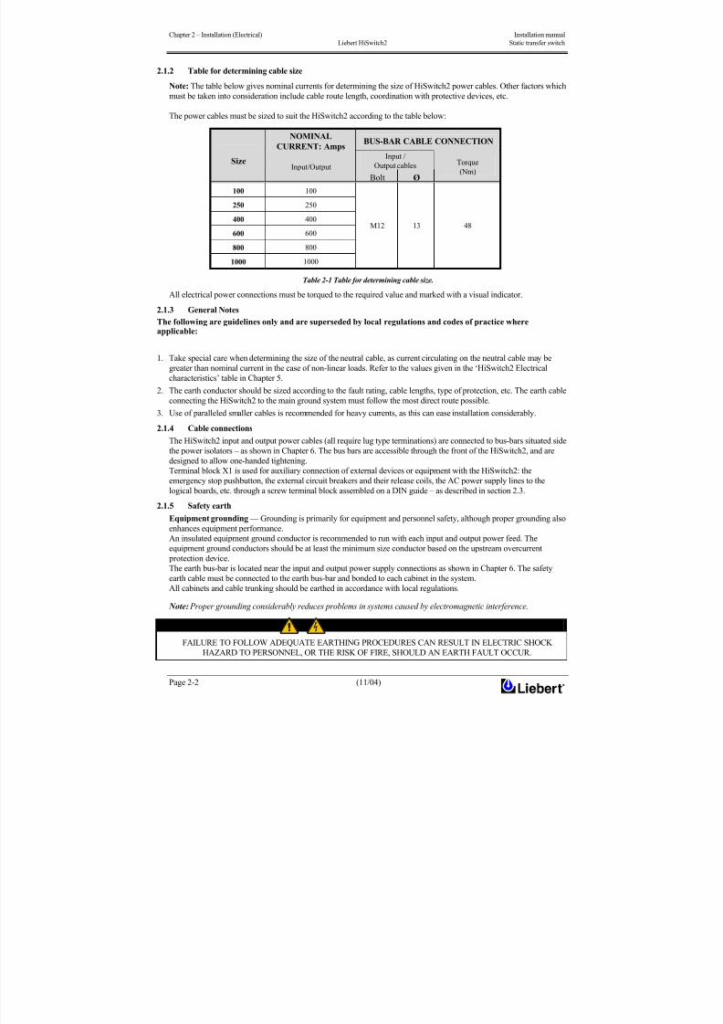
The power cables must be sized to suit the HiSwitch2 according to the table below:
NOMINAL
CURRENT: AmpsBUS-BAR CABLE CONNECTION
Input /
Output cablesSize
Input/Output
Bolt Ø
Torque
(Nm)
100 100
250 250
400 400
600 600
800 800
1000 1000
M12 13 48
Table 2-1 Table for determining cable size.
All electrical power connections must be torqued to the required value and marked with a visual indicator.
2.1.3 General Notes
The following are guidelines only and are superseded by local regulations and codes of practice whereapplicable:
1. Take special care when determining the size of the neutral cable, as current circulating on the neutral cable may be
greater than nominal current in the case of non-linear loads. Refer to the values given in the ‘HiSwitch2 Electrical
characteristics’ table in Chapter 5.2. The earth conductor should be sized according to the fault rating, cable lengths, type of protection, etc. The earth cable
connecting the HiSwitch2 to the main ground system must follow the most direct route possible.
3. Use of paralleled smaller cables is recommended for heavy currents, as this can ease installation considerably.
2.1.4 Cable connections
The HiSwitch2 input and output power cables (all require lug type terminations) are connected to bus-bars situated side
the power isolators – as shown in Chapter 6. The bus bars are accessible through the front of the HiSwitch2, and are
designed to allow one-handed tightening.
Terminal block X1 is used for auxiliary connection of external devices or equipment with the HiSwitch2: the
emergency stop pushbutton, the external circuit breakers and their release coils, the AC power supply lines to the
logical boards, etc. through a screw terminal block assembled on a DIN guide – as described in section 2.3.
2.1.5 Safety earthEquipment grounding — Grounding is primarily for equipment and personnel safety, although proper grounding also
enhances equipment performance.
An insulated equipment ground conductor is recommended to run with each input and output power feed. The
equipment ground conductors should be at least the minimum size conductor based on the upstream overcurrent
protection device.
The earth bus-bar is located near the input and output power supply connections as shown in Chapter 6. The safety
earth cable must be connected to the earth bus-bar and bonded to each cabinet in the system.
All cabinets and cable trunking should be earthed in accordance with local regulations.
Note: Proper grounding considerably reduces problems in systems caused by electromagnetic interference.
WARNING
FAILURE TO FOLLOW ADEQUATE EARTHING PROCEDURES CAN RESULT IN ELECTRIC SHOCK
HAZARD TO PERSONNEL, OR THE RISK OF FIRE, SHOULD AN EARTH FAULT OCCUR.

8/11/2019 HiSwitch 2
http://slidepdf.com/reader/full/hiswitch-2 19/112
Installation manual Chapter 2 – Installation (Electrical)
Static transfer switch Liebert HiSwitch2
(11/04) Page 2-3
2.1.6 Protective devices
For safety reasons it is necessary to install circuit breaking protective devices in the input AC power supply and toward
the load, external to the system. As every installation is unique, this chapter provides general information of use to
qualified installation engineers who are familiar with operating practices, local regulations and the equipment to be
installed.
Protection against excessive overcurrents and short circuits in the power supply lines:Lines must be protected by installing suitable protective devices on the distribution panel of the incoming mains supply,
considering that the protection must be selective with system overload capacity (see Chapter 5 – Technical
Specifications: - Electrical Characteristics).
Input:
Power isolators inside the HiSwitch2 are typically not automatic and make use of devices located upstream for
protection against overcurrents.
These protective devices must be of appropriate size for a capacity which is the same as or less than the switches
incorporated in the HiSwitch2.
The AC lines powering the logical boards (LINE IN 1&2) must be fitted with appropriate protective devices and circuit
breakers, upstream of the external circuit breakers. There are protective fuses in the HiSwitch2, in series with these
inputs (F7÷10) (refer to figure 7-2).
Protection against earth faults (RCD devices):
In the event of a differential (RCD) device being installed upstream of the input supply, one must take into account the
transient and steady state earth leakage currents that are produced during start-up of the HiSwitch2.
The presence of an RFI suppression filter inside the HiSwitch2, determines a residual earth current greater than 3.5 mA
and less than 1000 mA.
Residual current circuit breakers (RCCB) must be sensitive to d.c. unidirectional pulse (class A) in the network and
insensitive to transient current pulses.
They are identified by the symbols respectively:
These isolators must have an average sensitivity, adjustable between 0.3 and 1A.
Output:
Load distribution line protection devices can also be used: before you use them, ensure that they discriminate with
respect to the HiSwitch2 input protection devices.
Note
All HiSwitch2 units are fuseless and are UL rated for use with upstream circuit breakers only.

8/11/2019 HiSwitch 2
http://slidepdf.com/reader/full/hiswitch-2 20/112
Chapter 2 – Installation (Electrical) Installation manual
Liebert HiSwitch2 Static transfer switch
Page 2-4 (11/04)
2.1.7 Wiring procedure
Important
The operations described in this section must be performed by authorised electricians or qualified technical
personnel. If you have any difficulties do not hesitate to contact our Customer Service & Support department atthe address given at the beginning of this manual.
WARNING
The HiSwitch2 will work only with an AC power source with a permanent neutral, safely earthed (TN systems).
Failure to comply with these requirements will result in damage to the unit.
With the equipment bolted in its final position, connect up the power cables as described below.
Examine the reference drawing in Chapter 6.
1. Check that the HiSwitch2 is totally isolated from its external power source and that all the STS’s power switches
are open. Put up danger signs to prevent inadvertent operations.
2. Open the HiSwitch2 cabinet access door and remove the metal guard on the lower side to permit access to the
connection bars. The metal guard on the HiSwitch2 cabinet must be removed after removing all power switch
handles.
3. Connect the equipment’s safety earth to the copper earthing wire installed in the bottom of the HiSwitch2
cabinet, underneath the power supply connections. Also connect the safety earthing cable to the earth of all other
devices in the system.
Note: Earthing connections and neutral connections must comply with the applicable local regulations and
standards.
Mains 1 incoming power connections
4. Connect the MAINS 1 AC power cables to the bus-bars on input 1 (terminals U1-V1-W1) of the HiSwitch2
and tighten the connections to the torque specified in Table 2-1 on the basis of size.
The Neutral cable must be connected to the input bus-bar identified as terminal N (see Note *- page 1-1).
CHECK FOR CORRECT PHASE ROTATION.
Mains 2 incoming power connections
5. Connect the MAINS 2 AC power supply cables to the bus-bars on input 2 (terminals U2-V2-W2) of the
HiSwitch2 and tighten the connections to the torque specified in Table 2-1 on the basis of size.
The Neutral cable must be connected to the input bus-bar identified as terminal N (see Note *- page 1-1).
CHECK FOR CORRECT PHASE ROTATION.

8/11/2019 HiSwitch 2
http://slidepdf.com/reader/full/hiswitch-2 21/112
Installation manual Chapter 2 – Installation (Electrical)
Static transfer switch Liebert HiSwitch2
(11/04) Page 2-5
Output connections
6. Connect the output cables between the output bars (U3-V3-W3-N) of the HiSwitch2 and the load distribution
panel and tighten connections to the torque specified in Table 2-1 on the basis of size.
CHECK THAT PHASES ARE CONNECTED IN THE RIGHT ORDER
WARNING
If the load cannot be connected to the system, check that the power cables toward the load are insulated and
made safe at the end of the connection segment.
Auxiliary connections
7. Connect to terminal block X1 the auxiliary cables of devices or equipment external to the HiSwitch2, such as:
external emergency stop, AC power lines supplying logical boards, external circuit breaker release coils, etc. (as
shown in section 2.3).
8. Connect the cables of any external devices for remote signalling (or external controls) to the corresponding
output connections (or terminal blocks) on the optional boards (see Chapter 6).
9. Reassemble all the lower metal guards removed previously.
2.2 Distance from floor to connection point on the equipment:
HiSwitch2 100/250AMinimum distance
(mm)
HiSwitch2 400/600AMinimum distance
(mm)
HiSwitch2 800/1000AMinimum distance
(mm)
Mains 1 incoming AC power supply
Mains 2 incoming AC power supply
1020 1280 1670
Output 800 950 1100
Neutral 600 950
Auxiliary terminal block (X1) 1050
Earth 350 1000
Table 2-2 .

8/11/2019 HiSwitch 2
http://slidepdf.com/reader/full/hiswitch-2 22/112
8/11/2019 HiSwitch 2
http://slidepdf.com/reader/full/hiswitch-2 23/112
Installation manual Chapter 2 – Installation (Electrical)
Static transfer switch Liebert HiSwitch2
(11/04) Page 2-7
2.3.3 Emergency stop
The HiSwitch2 cabinet is prepared for installation of an external emergency stop button, as shown in the figure below.
Terminal X1 is prepared for connection of release coils for external circuit breakers located in the optional cabinet
external to the HiSwitch2.
Note: the remote emergency pushbutton may be installed only if there are external circuit breakers with release coils.
IMPORTANT
Assemble a circuit breaker with a release coil upstream of each incoming power supply, so that when the emergency button
is pressed the HiSwitch2 will be cut off from its power sources (there will no longer be power to the load).
Pressing the external emergency button does not result in any alarm signal appearing on the operator panel display, though
there will be alarms caused by the failure of the incoming power mains.
The external stop button must be located in a visible position which is easily accessible in the event of an emergency.
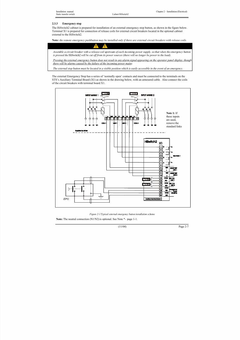
The external Emergency Stop has a series of ‘normally open’ contacts and must be connected to the terminals on the
STS’s Auxiliary Terminal Board (X1) as shown in the drawing below, with an armoured cable. Also connect the coils
of the circuit breakers with terminal board X1.
Figure 2-1 Typical external emergency button installation scheme
Note: The neutral connection (N1/N2) is optional. See Note *- page 1-1.
EPO
Note 1: If
these inputs
are used,
remove the
standard links
8/11/2019 HiSwitch 2
http://slidepdf.com/reader/full/hiswitch-2 24/112
Chapter 2 – Installation (Electrical) Installation manual
Liebert HiSwitch2 Static transfer switch
Page 2-8 (11/04)
2.3.4 Power supply
The HiSwitch2 is supplied with redundant power supplies that are designed to operate from a voltage range of 200V to
415V. The unit is set at the factory to match the nameplate voltage. Field adjustments are not necessary. If the unit
needs to operate at a voltage other than what is listed on the nameplate, contact Liebert Global Services or the local
Liebert representative.
Note
Ensure that the wiring for the control transformers matches the input voltage for the unit.
Improper wiring could result in blown fuses.

8/11/2019 HiSwitch 2
http://slidepdf.com/reader/full/hiswitch-2 25/112
Installation manual Chapter 3 – Optional equipment
Static transfer switch Liebert HiSwitch2 Installation notes
(11/04) Page 3-1
3 Chapter 3 – Optional equipment – Installation notes
3.1.1 Introduction
The configuration of a system incorporating the HiSwitch2 depends on the specific needs of the installation under
consideration.
An installation consists of a number of items of equipment, devices and optional additional boards. The options may be
prepared for installation either in the factory or directly by the customer.
HiSwitch2 is a member of a family of constant power control products, and is supported by an extensive customer
service network.
Brief notes on installation of available options are provided below.
Installers must be thoroughly familiar with the product. More detailed information on installation procedures is
provided in the Technical Assistance commissioning manual.
Options:
The following options are available for the HiSwitch2:
• Remote Source Selection board
• Key Lockout Switch
• Redundant Output Breaker• Seismic Floor Anchors
Communications options:
• Programmable Relay Board (PRB)
• Input Contact Isolator (ICI) Board
• Comms Board w/SiteScan and Modem Interface
• Internal Modem
• Network Interface Card (NIC)
WARNING
All options must be installed by Liebert global services or Liebert factory-authorized service
provided by a Liebert distributor. The option area and customer control cable area contain hazardous
voltages if any of the input sources are on, even when the unit is in bypass. Turn all power sources off
before installing customer control cables to any option
3.1.2 Remote Source Selection
An optional Remote Source Selection board may be installed in your HiSwitch2. This board is installed in the same bay
as the communications options.
The Remote Source Selection allows the preferred input source to be chosen from a remote location.
A user supplied normally open dry contact allows the user to remotely select a source to be the preferred source in thesame process as the local source transfer selection.
The unit’s preferred source selection and Remote Source Selection are active at the same time, with the HiSwitch2
following the last request for a preferred source change, regardless of whether it was from the local or Remote Source
Selection controls.
See Chapter 9 - Enabling Remote Source Selection for instructions on enabling the Remote Source Selection.
See Figures in Chapter 6 for the location of the Remote Source Selection option.
Figure below shows the wiring details.
8/11/2019 HiSwitch 2
http://slidepdf.com/reader/full/hiswitch-2 26/112
Chapter 3 – Optional equipment Installation manual
Installation notes Liebert HiSwitch2 Static transfer switch
Page 3-2 (11/04)
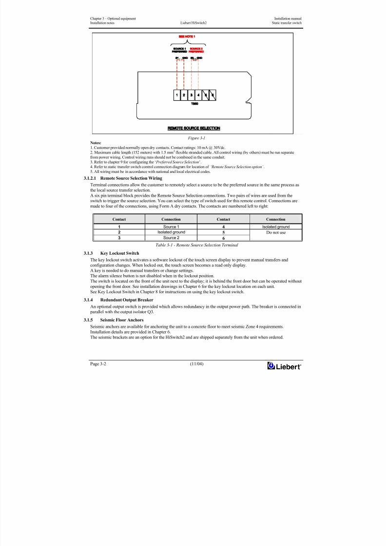
Figure 3-1
Notes:
1. Customer provided normally open dry contacts. Contact ratings: 10 mA @ 30Vdc.
2. Maximum cable length (152 meters) with 1.5 mm2 flexible stranded cable. All control wiring (by others) must be run separate
from power wiring. Control wiring runs should not be combined in the same conduit.
3. Refer to chapter 9 for configuring the ‘ Preferred Source Selection’.
4. Refer to static transfer switch control connection diagram for location of ‘Remote Source Selection option’ .
5. All wiring must be in accordance with national and local electrical codes.
3.1.2.1 Remote Source Selection Wiring
Terminal connections allow the customer to remotely select a source to be the preferred source in the same process as
the local source transfer selection.
A six pin terminal block provides the Remote Source Selection connections. Two pairs of wires are used from the
switch to trigger the source selection. You can select the type of switch used for this remote control. Connections aremade to four of the connections, using Form A dry contacts. The contacts are numbered left to right:
Contact Connection Contact Connection
1 Source 1 4 Isolated ground
2 Isolated ground 5
3 Source 2 6
Do not use
Table 3-1 - Remote Source Selection Terminal
3.1.3 Key Lockout Switch
The key lockout switch activates a software lockout of the touch screen display to prevent manual transfers and
configuration changes. When locked out, the touch screen becomes a read only display.
A key is needed to do manual transfers or change settings.The alarm silence button is not disabled when in the lockout position.
The switch is located on the front of the unit next to the display; it is behind the front door but can be operated without
opening the front door. See installation drawings in Chapter 6 for the key lockout location on each unit.
See Key Lockout Switch in Chapter 8 for instructions on using the key lockout switch.
3.1.4 Redundant Output Breaker
An optional output switch is provided which allows redundancy in the output power path. The breaker is connected in
parallel with the output isolator Q3.
3.1.5 Seismic Floor Anchors
Seismic anchors are available for anchoring the unit to a concrete floor to meet seismic Zone 4 requirements.
Installation details are provided in Chapter 6.
The seismic brackets are an option for the HiSwitch2 and are shipped separately from the unit when ordered.

8/11/2019 HiSwitch 2
http://slidepdf.com/reader/full/hiswitch-2 27/112
Installation manual Chapter 3 – Optional equipment
Static transfer switch Liebert HiSwitch2 Installation notes
(11/04) Page 3-3
3.1.6 Programmable Relay Board
The Programmable Relay Board (PRB) provides a means to trigger an external device when an event occurs in the
HiSwitch2. Each PRB has 8 channels. Each channel has two sets of Form-C dry contacts, rated 1 Amp @ 30 VDC or
250 mAmp @ 125 VAC.
Any alarm/event can be programmed to any channel or channels. Up to ten (10) events can be programmed to a relay.
If multiple events are grouped to one relay, group the events logically to simplify troubleshooting when an event is
triggered. The same alarm/event can be programmed to more than one channel. Up to two Programmable Relay Boardscan be installed in the HiSwitch2 for a total of 16 channels. Programming is performed through the touch screen
display.
See Configuring the Programmable Relay Board Settings in Chapter 11 for default settings and instructions for
reconfiguring the relays. See figures in Chapter 6 for the location of the PRB. Figure below shows the wiring details.
Table 8 provides the PRB pinout.
Figure 3-2
Notes:
1. Customer control wiring connection points are terminal blocks 1 through 15.
2. Programmable relay board option includes 8 signal channels with (2) form-c dry contacts per channel. See table below.3. Refer to chapter 11 for configuring the programmable relay board option.
4. All control wiring (by others) must be run separate from power wiring. Control wiring runs should not be combined in the same
conduit.
5. Refer to static transfer switch control connection diagram for location of program relay board option.
6. Contact ratings: 1 A @ 30Vdc, 200 mA @125Vac.
7. Maximum cable length (152 meters) with 1.5 mm2 flexible stranded cable.
8. All wiring must be in accordance with national and local electrical codes.
PROGRAMMABLE RELAY BOARD
J71
J72
J73J74

8/11/2019 HiSwitch 2
http://slidepdf.com/reader/full/hiswitch-2 28/112
Chapter 3 – Optional equipment Installation manual
Installation notes Liebert HiSwitch2 Static transfer switch
Page 3-4 (11/04)
3.1.7 Input Contact Isolator Board
The Input Contact Isolator Board (ICI) provides an HiSwitch2 module interface for up to eight external user alarm or
message inputs to be routed through the static transfer switch’s alarm network. The eight contacts are normally open
dry contacts. When a contact closes, an event is triggered.
The Input Contact Isolator options are configured through the Input Contact Isolator dialog box, which is accessed from
the Comm Option dialog box on the touch screen display. You also can program the alarm messages through this
dialog box. See Configuring the Input Contact Isolator Settings in Chapter 11 for instructions on configuring theconnections.
See figures in Chapter 6 for the location of the ICI. Figure below shows the wiring details.
Figure 3-3
Notes:
1. Customer control wiring connection points are terminal blocks 1 through 16 (See table J51).
2. Customer provided normally open dry contacts for user alarm messages.
3. Refer to chapter 11 for configuring the ‘input contact isolator board option’.
4. All control wiring (by others) must be run separate from power wiring. control wiring runs should not be combined in the same
conduit.
5. Refer to static transfer switch control connection diagram for location of ‘input contact isolator board option’ .6. Signal voltage: 100 mA @ 12Vdc.
7. Maximum cable length (152 meters) with # 1.5 mm2 flexible stranded cable.
8. All wiring must be in accordance with national and local electrical codes.
2
3
1
PIN NO.
TABLE (J51)
INPUTCONTACT
1
234
6
5
4
910
78
56
1112
7
8 1516
1413
J51
8/11/2019 HiSwitch 2
http://slidepdf.com/reader/full/hiswitch-2 29/112
Installation manual Chapter 3 – Optional equipment
Static transfer switch Liebert HiSwitch2 Installation notes
(11/04) Page 3-5
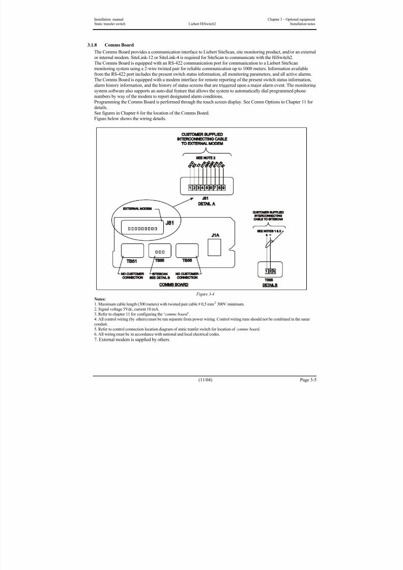
3.1.8 Comms Board
The Comms Board provides a communication interface to Liebert SiteScan, site monitoring product, and/or an external
or internal modem. SiteLink-12 or SiteLink-4 is required for SiteScan to communicate with the HiSwitch2.
The Comms Board is equipped with an RS-422 communication port for communication to a Liebert SiteScan
monitoring system using a 2-wire twisted pair for reliable communication up to 1000 meters. Information availablefrom the RS-422 port includes the present switch status information, all monitoring parameters, and all active alarms.
The Comms Board is equipped with a modem interface for remote reporting of the present switch status information,
alarm history information, and the history of status screens that are triggered upon a major alarm event. The monitoring
system software also supports an auto-dial feature that allows the system to automatically dial programmed phone
numbers by way of the modem to report designated alarm conditions.
Programming the Comms Board is performed through the touch screen display. See Comm Options in Chapter 11 for
details.
See figures in Chapter 6 for the location of the Comms Board.
Figure below shows the wiring details.
Figure 3-4
Notes:
1. Maximum cable length (300 meters) with twisted pair cable # 0,5 mm2 300V minimum.
2. Signal voltage 5Vdc, current 10 mA.
3. Refer to chapter 11 for configuring the ‘comms board ’.
4. All control wiring (by others) must be run separate from power wiring. Control wiring runs should not be combined in the same
conduit.
5. Refer to control connection location diagram of static tranfer switch for location of comms board .
6. All wiring must be in accordance with national and local electrical codes.
7. External modem is supplied by others.
8/11/2019 HiSwitch 2
http://slidepdf.com/reader/full/hiswitch-2 30/112
Chapter 3 – Optional equipment Installation manual
Installation notes Liebert HiSwitch2 Static transfer switch
Page 3-6 (11/04)
This page is left blank intentionally

8/11/2019 HiSwitch 2
http://slidepdf.com/reader/full/hiswitch-2 31/112
Installation manual Chapter 4 – Communication System
Static transfer switch Liebert HiSwitch2 Installation notes
(11/04) Page 4-1
4 Chapter 4 – Communication System
4.1 Introduction
HiSwitch2 enables to use the communication system to send all the most relevant information related to its operating
condition (in real time), its alarm history and its event history, depending on the customer's specific requirements. If
appropriate optional boards are installed, it is also possible to remotely display the most relevant alarms or user-definedones.
Supervision can be carried out from a local or remote location.
The HiSwitch2 monitoring system offers several choices for communications. They are:
RS-232 terminal port (std)
OPTIONS: Internal modem
Network Interface Card (NIC)
Input Contact Isolator (ICI) Board
Programmable Relay Board (PRB)
Comms Board

8/11/2019 HiSwitch 2
http://slidepdf.com/reader/full/hiswitch-2 32/112

8/11/2019 HiSwitch 2
http://slidepdf.com/reader/full/hiswitch-2 33/112
Installation manual Chapter 4 – Communication System
Static transfer switch Liebert HiSwitch2 Installation notes
(11/04) Page 4-3
RS-232 Interface Parameters:
The service terminal interface parameters are the following settings and cannot be changed.
Parameter Settings
Interface RS-232 Using EIA Voltage Levels
Baud Rate 9600
Parity None
Number of Data Bits 8
Number of Stop Bits 1
Hardware Flow Control Off
Terminator <CR> <LF>
Handshaking Not supported
Structure Full duplex
Local Echo Off
Table 4-3
4.2.2 Connecting and Using a Terminal
An RS-232 connection can be used to connect the HiSwitch2 to either a terminal or a PC running terminal emulation
software. If you are unsure of the cable pin out, see Terminal Port in previous section.
1. Connect the terminal to the HiSwitch2 by plugging the cable from the terminal into the RS-232 port.
This connection can be made at any time.
2. After making the connection, verify the communications link by pressing <ENTER> on the terminal keyboard.
The interface communications system responds as indicated below:
Repeating command -->
Illegal command!<?> or <HELP?> displays the RS-232 command set<?> <command> or <HELP?> <command> displays specific help for the commandSVTP-Control >The SVTP-Control > prompt indicates that RS-232 communications are established.
• If you receive no response or prompt, verify that the connector is properly plugged into the port and the PC or
terminal serial interface is working properly.
3. Enter the desired commands, as listed in Table below:
For additional help type <?> <command> or <HELP?> <command>
Refer to the corresponding menu options in the Chapter 11 for more details about the commands.
Some terminal commands require a password to function. Use the PWD command and a valid password to gain access.

8/11/2019 HiSwitch 2
http://slidepdf.com/reader/full/hiswitch-2 34/112
Chapter 4 –Communication System Installation manual
Installation notes Liebert HiSwitch2 Static transfer switch
Page 4-4 (11/04)
Keys Function ? Displays this help menu or specific help with a command AA? Displays active alarms AF? Displays active faults CEL Clears the event log
CHL Clears the history logsDATE? Displays current system date
DATE Sets system date
EL? Displays the entire event log
HELP? Displays this help menu or specific help with a command
HLn? Displays the history log #n, if frozen
LOGOUT Logs user out of unprotected mode
PS? Displays the preferred source
PS n Sets the preferred source to #n
PWD Allows users to access protected commands
QUIT Modem only. Ends the session and hangs up the modem.
SH Silences the horn
SPT? Displays all current setpoints
Keys Function SPTx Displays current setpoints for group x. See Configuring the HiSwitch2 via the Terminal for a
description of groups.
SR? Displays status reports
TIME? Displays current system time
TIME Sets system time
UPMDR? Displays metering data
VER? Displays firmware versions
Table 4-4 – Terminal/ Modem Commands
4.2.3 Configuring the HiSwitch2 via the Terminal
The SPT command is used to configure the systems setpoints. The SVT syntax for the setpoints consists for four
parameters:
SPT [group] [item] [value]where the parameters are:
• SPT — is the terminal command that is used to configure setpoints.
• group — the group under the setpoint command which contains the desired settings.
• item — the item number within the selected group.
• value — the desired value for this item.
Only the specific options words listed in this section use a hexadecimal value. Other settings, depending on what they
are, use other input types. For example, System ID uses a text string, nominal voltages and currents use standard
numeric integers, and modem baud rate uses an enumeration where 0 = 2400, 1 = 9600, & 2 = 19200 bps.
Note
Spaces are placed between each parameter, but not between characters or numbers in a parameter. Using an
underline here to represent a space, an example of a the syntax is: SPT_2_6_0081. 0081 is the value parameter.
This section provides instructions for setting these parameters, with an example of building an SPT command for
System and User settings.
4.2.3.1 Groups Parameter
The setpoints are grouped for ease of configuration. For example, Event Masks are group 4 and System Settings are
group 2. The numbers shown below are entered for the group parameter. For example, start of a System Settings
command is SPT 2.
The group parameters are:
1 = System Ratings
2 = System Settings
3 = User Settings
4 = Event Mask SettingsFor example, the start of a System Settings command is SPT 2, where SPT is the system setpoints command and 2 is
the group parameter for System Settings.
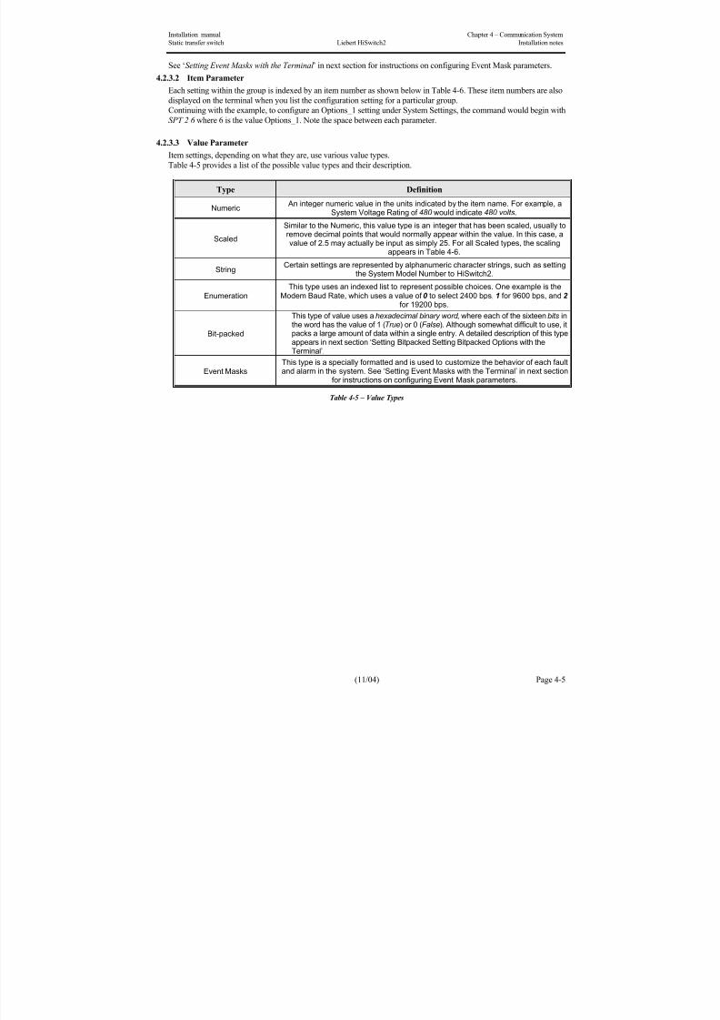
8/11/2019 HiSwitch 2
http://slidepdf.com/reader/full/hiswitch-2 35/112
Installation manual Chapter 4 – Communication System
Static transfer switch Liebert HiSwitch2 Installation notes
(11/04) Page 4-5
See ‘Setting Event Masks with the Terminal ’ in next section for instructions on configuring Event Mask parameters.
4.2.3.2 Item Parameter
Each setting within the group is indexed by an item number as shown below in Table 4-6. These item numbers are also
displayed on the terminal when you list the configuration setting for a particular group.
Continuing with the example, to configure an Options_1 setting under System Settings, the command would begin with
SPT 2 6 where 6 is the value Options_1. Note the space between each parameter.
4.2.3.3 Value Parameter
Item settings, depending on what they are, use various value types.
Table 4-5 provides a list of the possible value types and their description.
Type Definition
Numeric An integer numeric value in the units indicated by the item name. For example, a
System Voltage Rating of 480 would indicate 480 volts.
Scaled
Similar to the Numeric, this value type is an integer that has been scaled, usually toremove decimal points that would normally appear within the value. In this case, avalue of 2.5 may actually be input as simply 25. For all Scaled types, the scaling
appears in Table 4-6.
StringCertain settings are represented by alphanumeric character strings, such as setting
the System Model Number to HiSwitch2.
Enumeration
This type uses an indexed list to represent possible choices. One example is theModem Baud Rate, which uses a value of 0 to select 2400 bps, 1 for 9600 bps, and 2
for 19200 bps.
Bit-packed
This type of value uses a hexadecimal binary word , where each of the sixteen bits inthe word has the value of 1 (True) or 0 (False). Although somewhat difficult to use, itpacks a large amount of data within a single entry. A detailed description of this typeappears in next section ‘Setting Bitpacked Setting Bitpacked Options with theTerminal’.
Event MasksThis type is a specially formatted and is used to customize the behavior of each faultand alarm in the system. See ‘Setting Event Masks with the Terminal’ in next section
for instructions on configuring Event Mask parameters.
Table 4-5 – Value Types
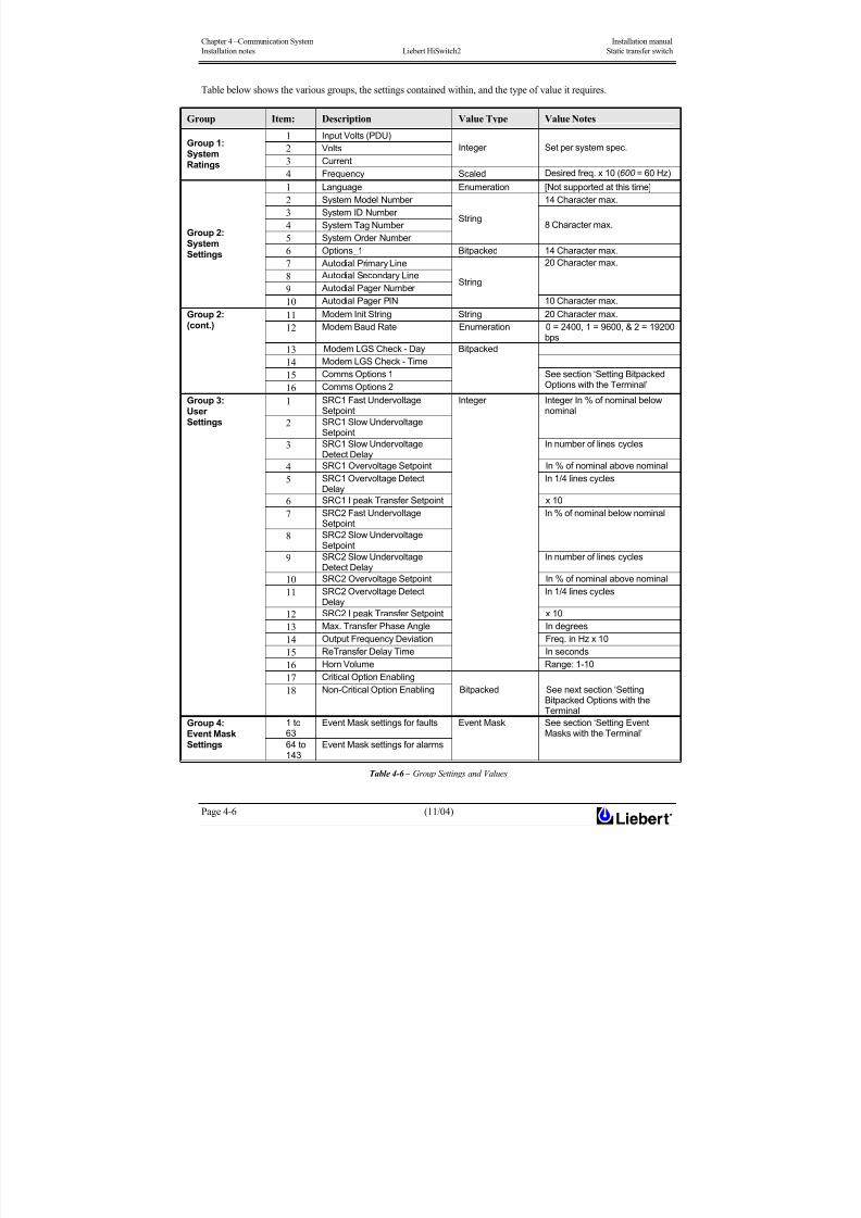
8/11/2019 HiSwitch 2
http://slidepdf.com/reader/full/hiswitch-2 36/112
Chapter 4 –Communication System Installation manual
Installation notes Liebert HiSwitch2 Static transfer switch
Page 4-6 (11/04)
Table below shows the various groups, the settings contained within, and the type of value it requires.
Group Item: Description Value Type Value Notes
1 Input Volts (PDU)
2 Volts 3 Current
Integer Set per system spec. Group 1:
SystemRatings
4 Frequency Scaled Desired freq. x 10 (600 = 60 Hz)
1 Language Enumeration [Not supported at this time]
2 System Model Number 14 Character max.
3 System ID Number
4 System Tag Number
5 System Order Number
String 8 Character max.
6 Options_1 Bitpacked 14 Character max.
7 Autodial Primary Line
8 Autodial Secondary Line
9 Autodial Pager Number
20 Character max.
Group 2:SystemSettings
10 Autodial Pager PIN
String
10 Character max. 11 Modem Init String String 20 Character max.
12 Modem Baud Rate Enumeration 0 = 2400, 1 = 9600, & 2 = 19200bps
13 Modem LGS Check - Day
14 Modem LGS Check - Time
15 Comms Options 1
Group 2:(cont.)
16 Comms Options 2
Bitpacked
See section ‘Setting BitpackedOptions with the Terminal’
1 SRC1 Fast UndervoltageSetpoint
2 SRC1 Slow UndervoltageSetpoint
Integer In % of nominal belownominal
3 SRC1 Slow Undervoltage
Detect Delay
In number of lines cycles
4 SRC1 Overvoltage Setpoint In % of nominal above nominal
5 SRC1 Overvoltage DetectDelay
In 1/4 lines cycles
6 SRC1 I peak Transfer Setpoint x 10
7 SRC2 Fast UndervoltageSetpoint
8 SRC2 Slow UndervoltageSetpoint
In % of nominal below nominal
9 SRC2 Slow UndervoltageDetect Delay
In number of lines cycles
10 SRC2 Overvoltage Setpoint In % of nominal above nominal
11 SRC2 Overvoltage Detect
Delay
In 1/4 lines cycles
12 SRC2 I peak Transfer Setpoint x 10
13 Max. Transfer Phase Angle In degrees
14 Output Frequency Deviation Freq. in Hz x 10
15 ReTransfer Delay Time In seconds
16 Horn Volume
Integer
Range: 1-10
17 Critical Option Enabling
Group 3:UserSettings
18 Non-Critical Option Enabling Bitpacked See next section ‘SettingBitpacked Options with theTerminal’
1 to63
Event Mask settings for faultsGroup 4:Event MaskSettings 64 to
143
Event Mask settings for alarms
Event Mask See section ‘Setting EventMasks with the Terminal’
Table 4-6 – Group Settings and Values
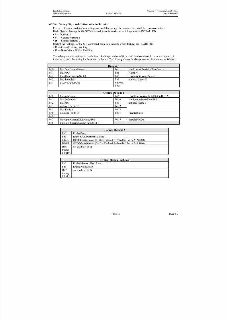
8/11/2019 HiSwitch 2
http://slidepdf.com/reader/full/hiswitch-2 37/112
Installation manual Chapter 4 – Communication System
Static transfer switch Liebert HiSwitch2 Installation notes
(11/04) Page 4-7
4.2.3.4 Setting Bitpacked Options with the Terminal
Five sets of options and features settings are available through the terminal to control the system operation.
Under System Settings for the SPT command, these items denote which options are INSTALLED:
• 6 — Options_1
• 14 — Comms Options 1
• 15 — Comms Options 2
Under User Settings, for the SPT command, these items denote which features are ENABLED:
• 17 — Critical Option Enabling
• 18 — Non-Critical Option Enabling
The value parameter settings are in the form of a bit-packed word (in hexidecimal notation). In other words, each bit
indicates a particular setting for the option or feature. The bit assignments for the options and features are as follows:
Options_1
bit0 HasDualOutputBreaker bit5 HasExternalPrecisionTimeSource
bit1 HasPDU bit6 HasSFA
bit2 Has4PoleTransferSwitch bit7 HasRemoteSourceSelect
bit3 HasShuntTrip bit4 asWyeOutputXfmr
bit8through
bit15
not used (set to 0)
Comms Options 1
bit0 HasIntModem bit9 HasOpenCommsDigitalOutputBrd_2
bit1 HasExtModem bit10 HasRemoteStatusPanelBrd_1
bit2 HasNIC bit11
bit3 not used (set to 0) bit12
bit4 HasSiteScan bit13
not used (set to 0)
bit5
bit6
not used (set to 0) bit14 EnableDialIn
bit7 HasOpenCommsDigitalInputBrd bit15 EnableDialOut bit8 HasOpenCommsDigitalOutputBrd_1
Comms Options 2
bit0 EnablePager
bit1 EnableOCDINormallyClosed
bit2-3 OCDO1Assignment (0=User Defined, 1=Standard Set or 2=AS400)
Bit4-5 OCDO2Assignment (0=User Defined, 1=Standard Set or 2=AS400)
Bit6
throug
h bit15
not used (set to 0)
Critical Option Enabling
bit0 EnableManual_IPeakReset
bit1 EnableAutoRestart
Bit2
throug
h bit15
not used (set to 0)
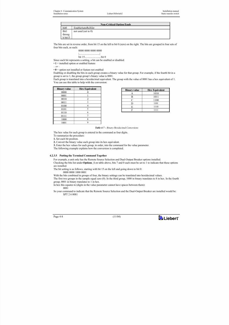
8/11/2019 HiSwitch 2
http://slidepdf.com/reader/full/hiswitch-2 38/112
Chapter 4 –Communication System Installation manual
Installation notes Liebert HiSwitch2 Static transfer switch
Page 4-8 (11/04)
Non-Critical Option Enab
bit0 EnableAutoReXfer
Bit1
throug
h bit15
not used (set to 0)
The bits are set in reverse order, from bit 15 on the left to bit 0 (zero) on the right. The bits are grouped in four sets of
four bits each, as such:
0000 0000 0000 0000
|................................|
bit 15.........................bit 0
Since each bit represents a setting, a bit can be enabled or disabled:
• 1 = installed option or enabled feature
– or –
• 0 = option not installed or feature not enabled
Enabling or disabling the bits in each group creates a binary value for that group. For example, if the fourth bit in a
group is set to 1, the group group’s binary value is 0001.
Each group is translated into a hexidecimal equivalent. The group with the value of 0001 has a hex equivalent of 1.You can use this table to help with the conversion:
Binary value Hex Equivalent
0000 0
0001 1
0010 2
0011 3
0100 4
0101 5
0110 6
0111 7
10008
1001 9
Table 4-7 – Binary-Hexidecimal Conversions
The hex value for each group is entered in the command as four digits.
To summarize the procedure:
1. Set each bit position.
2. Convert the binary value each group into its hex equivalent.
3. Enter the hex values for each group, in order, into the command for the value parameter.
The following example explains how the conversion is completed.
4.2.3.5 Putting the Terminal Command Together
For example, a unit only has the Remote Source Selection and Dual-Output Breaker options installed.Checking the bits list under Options_1 on table above, bits 7 and 0 each must be set to 1 to indicate that these options
are installed.
The bit setting is as follows, starting with bit 15 on the left and going down to bit 0:
0000 0000 1000 0001
With the bits combined in groups of four, the binary settings can be translated into hexidecimal values.
The first two groups in the sample equal zero (0). In the third group, 1000 in binary translates to 8 in hex. In the fourth
group, 0001 in binary translates to 1 in hex.
In hex this equates to (digits in the value parameter cannot have spaces between them):
0081
So your command to indicate that the Remote Source Selection and the Dual-Output Breaker are installed would be:
SPT 2 6 0081
Binary value Hex Equivalent
A 1010
B 1011
C 1100
D 1101
E 1110
F 1111

8/11/2019 HiSwitch 2
http://slidepdf.com/reader/full/hiswitch-2 39/112
Installation manual Chapter 4 – Communication System
Static transfer switch Liebert HiSwitch2 Installation notes
(11/04) Page 4-9
4.2.4 Setting Event Masks with the Terminal
The event masks can be customized via a terminal. The command SPT4?<ENTER> displays all faults and alarms,
along with their associated event masks. A plus sign (+) means that particular event mask is enabled, while a minus
sign (-) means that mask is disabled.
Refer to ‘Event Mask’ in Chapter 11 for more information on event masks and their associated flags.
Unlike the System and User Settings, mask values are set by designated letters, not hex values.
However, as with other RS-232 interface settings, four parameters are passed. See ‘Configuring the HiSwitch2 via theTerminal’ in this section for more details about the parameters.
The syntax for configuring event masks is:
SPT 4 ID ±D±L±S±E±A
• SPT — is the terminal command used to configure setpoints.
• 4 — setting (group parameter) for event masks, under System Settings.
• ID — event ID. The ID is the item parameter for this command. The ID numbers for each event are listed with the
events in Table 10-1 in Chapter 10.
• D,L,S,E,A — the event masks: Dial, Latch, Summary, Event log, and Audible. The masks are the value parameter for
the command.
Each mask type must be preceded by a plus sign (+) to enable it, or a minus sign (-) to disable it.
Note NO spaces are placed between each mask listed above.
Only the mask that is passed (enabled) is applied when the event occurs.
Note that the Summary and Event Log event masks are only configurable for the LED units.
To set the event masks for a particular event:
1. Enter the command. Examples and descriptions are provided below.
2. Press ENTER.
After the new settings are entered, the new results for that event ID are displayed.
4.2.4.1 Examples of Event Mask Settings
• To latch event #001, S1 SCR SHORT, use SPT 4 1 +L.
• To disable event #128, CONFIG MODIFIED, from sounding the horn, use SPT 4 100 -A.
• To enable event #012, OUT VOLT SENSE FAIL, to Dial and go into the Event Log, use SPT 4 12 +D+E.
• To disable all masks for event #120, INPUT CONTACT #1, use SPT 4 120 -D-L-S-E-A.
To breakdown this syntax for the last example:
• SPT — SVT command
• 4 — group parameter, identifying System Setting group under which the Event Mask settings reside.
• 120 — item parameter. In this command, that is the event ID.
• -D-L-S-E-A — value parameter. In this case, the minus sign (-) disables all masks for the INPUT CONTACT #1
event.
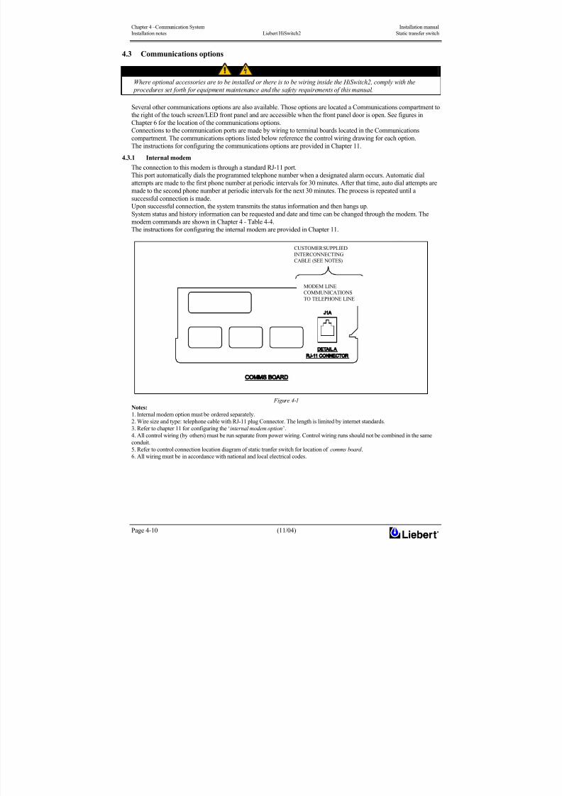
8/11/2019 HiSwitch 2
http://slidepdf.com/reader/full/hiswitch-2 40/112
Chapter 4 –Communication System Installation manual
Installation notes Liebert HiSwitch2 Static transfer switch
Page 4-10 (11/04)
4.3 Communications options
WARNING
Where optional accessories are to be installed or there is to be wiring inside the HiSwitch2, comply with the
procedures set forth for equipment maintenance and the safety requirements of this manual.
Several other communications options are also available. Those options are located a Communications compartment to
the right of the touch screen/LED front panel and are accessible when the front panel door is open. See figures in
Chapter 6 for the location of the communications options.
Connections to the communication ports are made by wiring to terminal boards located in the Communications
compartment. The communications options listed below reference the control wiring drawing for each option.
The instructions for configuring the communications options are provided in Chapter 11.
4.3.1 Internal modem
The connection to this modem is through a standard RJ-11 port.
This port automatically dials the programmed telephone number when a designated alarm occurs. Automatic dial
attempts are made to the first phone number at periodic intervals for 30 minutes. After that time, auto dial attempts are
made to the second phone number at periodic intervals for the next 30 minutes. The process is repeated until a
successful connection is made.Upon successful connection, the system transmits the status information and then hangs up.
System status and history information can be requested and date and time can be changed through the modem. The
modem commands are shown in Chapter 4 - Table 4-4.
The instructions for configuring the internal modem are provided in Chapter 11.
Figure 4-1
Notes:
1. Internal modem option must be ordered separately.
2. Wire size and type: telephone cable with RJ-11 plug Connector. The length is limited by internet standards.
3. Refer to chapter 11 for configuring the ‘internal modem option’.
4. All control wiring (by others) must be run separate from power wiring. Control wiring runs should not be combined in the same
conduit.
5. Refer to control connection location diagram of static tranfer switch for location of comms board .
6. All wiring must be in accordance with national and local electrical codes.
CUSTOMER SUPPLIED
INTERCONNECTING
CABLE (SEE NOTES)
MODEM LINE
COMMUNICATIONSTO TELEPHONE LINE

8/11/2019 HiSwitch 2
http://slidepdf.com/reader/full/hiswitch-2 41/112

8/11/2019 HiSwitch 2
http://slidepdf.com/reader/full/hiswitch-2 42/112

8/11/2019 HiSwitch 2
http://slidepdf.com/reader/full/hiswitch-2 43/112
Installation manual Chapter 5 – Technical specifications
Static transfer switch Liebert HiSwitch2
(11/04) Page 5-1
5 Chapter 5 – Technical SpecificationsThe tables below describe the typical features of static transfer switches (HiSwitch2).
5.1 Conformity and Standards
The static transfer switch is designed in accordance with the following standards:
Description Year Reference standards
General and safety requirements for
UPS used in operator access areas2002
EN 62040-1-1
IEC 62040-1-1
Emissions requirements 1995 EN 50091-2
Method of specifying the performance
and test requirements2001
EN 62040-3 identical to
IEC 62040-3 (1999)
Safety of information technology
equipment 2001 EN 60950
ISO 9001 Quality Certification — CCEE marked
5.2 Environmental Conditions
STSes are designed to resist the following environmental conditions without failures or compromised
operation:
ENVIRONMENTAL
CHARACTERISTICSUNIT
Nominal current A 100-1000
Operating temperature °C 0 to 40
Relative humidity — ≤ 95% not condensing
Installation altitude ≤1200m asl
Storage and transport temperature °C -40 ÷ +80
Operating Altitude above sea level
without deratingm
Up to 1200
(Above 1200 m output current is derated by 18% per 1000
m)
Audible noise dBA≤
55 dBA at 1.5 m with audible alarm off
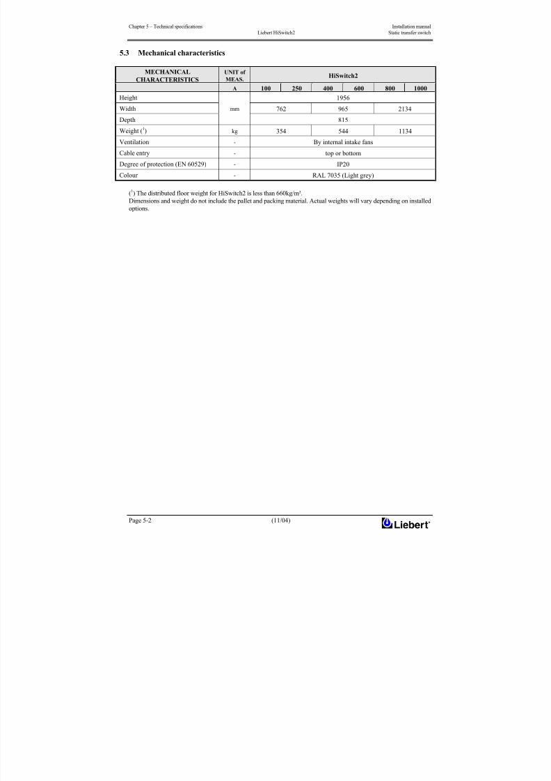
8/11/2019 HiSwitch 2
http://slidepdf.com/reader/full/hiswitch-2 44/112
Chapter 5 – Technical specifications Installation manual
Liebert HiSwitch2 Static transfer switch
Page 5-2 (11/04)
5.3 Mechanical characteristics
MECHANICAL
CHARACTERISTICS
UNIT of
MEAS.HiSwitch2
A 100 250 400 600 800 1000
Height 1956
Width 762 965 2134
Depth
mm
815
Weight (1) kg 354 544 1134
Ventilation - By internal intake fans
Cable entry - top or bottom
Degree of protection (EN 60529) - IP20
Colour - RAL 7035 (Light grey)
(1) The distributed floor weight for HiSwitch2 is less than 660kg/m².Dimensions and weight do not include the pallet and packing material. Actual weights will vary depending on installed
options.

8/11/2019 HiSwitch 2
http://slidepdf.com/reader/full/hiswitch-2 45/112
Installation manual Chapter 5 – Technical specifications
Static transfer switch Liebert HiSwitch2
(11/04) Page 5-3
5.4 Electrical Characteristics (Inputs)
INPUTS
UNIT of
MEAS.Nominal current A 100 1000
Nominal mains voltage Vac200, 208, 220, 240, 380, 400 or 415 (L-L) 50 Hz
from 200 to 415 (L-L) 60 Hz
Power supplyThree phase a.c. (3 or 4 wire-plus-ground).
The HiSwitch2 is designed to accept an input neutral from each source.
Mains voltage variation tolerance % The voltage shall be within ± 10 % of the nominal voltage.
Frequency Hz50 or 60
(factory setting)
Frequency tolerance Hzdefault ± 0.5
From 0.1 to 3.0 selectable every 0.1 Hz
5.5 Electrical Characteristics (Output)
OUTPUT DATA
UNIT of
MEAS.
Nominal current A 100 1000
Nominal voltage V AC200, 208, 220, 240, 380, 400 or 415 (L-L) 50 Hz
from 200 to 415 (L-L) 60 Hz
Power supplyThree phase a.c. (3 or 4 wire-plus-ground).
Nominal output voltage shall be same as input voltage.
Frequency Hz50 or 60
(factory setting)
Frequency tolerance Hzdefault ± 0.5
From 0.1 to 3.0 selectable every 0.1 Hz
System Current Ratings A 100 250 400 600 800 1000
125 % for 30 minutes 100A÷400A
125 % for 10 minutes 600A÷1000A
150 % for 2 minutesOverload Capability A
500 % for 0.25 sec.
Yield at nominal current > 99 %
Transfer mode Non short-circuiting switching (Break before Make)
Notes:
= Factory set for 400 Vac The HiSwitch2 is supplied with redundant power supplies that are designed to operate
from a voltage range of 200V to 415V.
= These ratings are based upon continuous switch current rating. These ratings are for all voltages and frequencies.All units are 100% continuous current rated.

8/11/2019 HiSwitch 2
http://slidepdf.com/reader/full/hiswitch-2 46/112
Chapter 5 – Technical specifications Installation manual
Liebert HiSwitch2 Static transfer switch
Page 5-4 (11/04)
5.6 General characteristics
100 1000 A
Switching:
Manual and automatic
Preferential mains may be selected
Retransfer may be set to Automatic/manual
Inhibition of transfer may be set for overload in output
Transfer time: ¼ cycle (5 ms)
3 pole configurations
Size of neutral: 2 In (if used)
SCR failure detection: open or short circuit (standard alarm only)
Accessible from front for maintenance work
Ventilation control device
Redundant fans
Operator display Led display panel or option LCD touch screen display panel
Parameters monitored
Voltage and current (input/output);
frequency for both power sources
apparent and active power in output,
phase difference in input,
number of transfers
Load Power Factor
Range0.75 to 1.0, leading or lagging
Load Crest Factor Up to 3.5
Source Voltage
DistortionUp to 10% THD with notches and ringing transients
Unit Voltage Unit Amps Withstand Capability
208-240V 100÷1000A 100kA
100-250A 65kA
400-600A 100kA
Unit Short Circuit
Withstand Capability
380-415V
800-1000A 65kA
Input Surge Suppression
The HiSwitch2 is equipped with transient voltage surge suppression on each input for maximum surge suppression.
The surge suppression is capable of protecting the HiSwitch2 from operating outside of tolerances due to surges as
defined by IEC 1000-4-5 (1.2/50uS surge, 2kV CM and 1kV DM) as required under EN 50091-2.
Response Time
A dual level fast/slow transfer threshold is used for under voltage detection to allow the HiSwitch2 to be compatible
with UPSs and generators. The voltage thresholds and the slow transfer delay time is user-adjustable. The fast transfer
delay time is less than 4 ms.
The over voltage detection uses a single threshold, with programmable level and delay time.
See Chapter 11 ‘User Settings’ for instructions on configuring these settings.
Environmental RequirementsSee ‘Location Considerations’ in Chapter 1 for details concerning environmental requirements for the HiSwitch2.

8/11/2019 HiSwitch 2
http://slidepdf.com/reader/full/hiswitch-2 47/112
Installation manual Chapter 6 – Installation drawing
Static transfer switch Liebert HiSwitch2
(11/04) Page 6-1
6 Chapter 6 – Installation drawings
6.1 Introduction
The drawings below illustrate the principal mechanical and electrical characteristics of the HiSwitch2 and of its various
optional cabinets.
In these drawings you will find all information of use for positioning the equipment, determining cable entry, making
electrical power and auxiliary connections, determining the position of isolators, determining the physical location of
various optional equipment, etc.
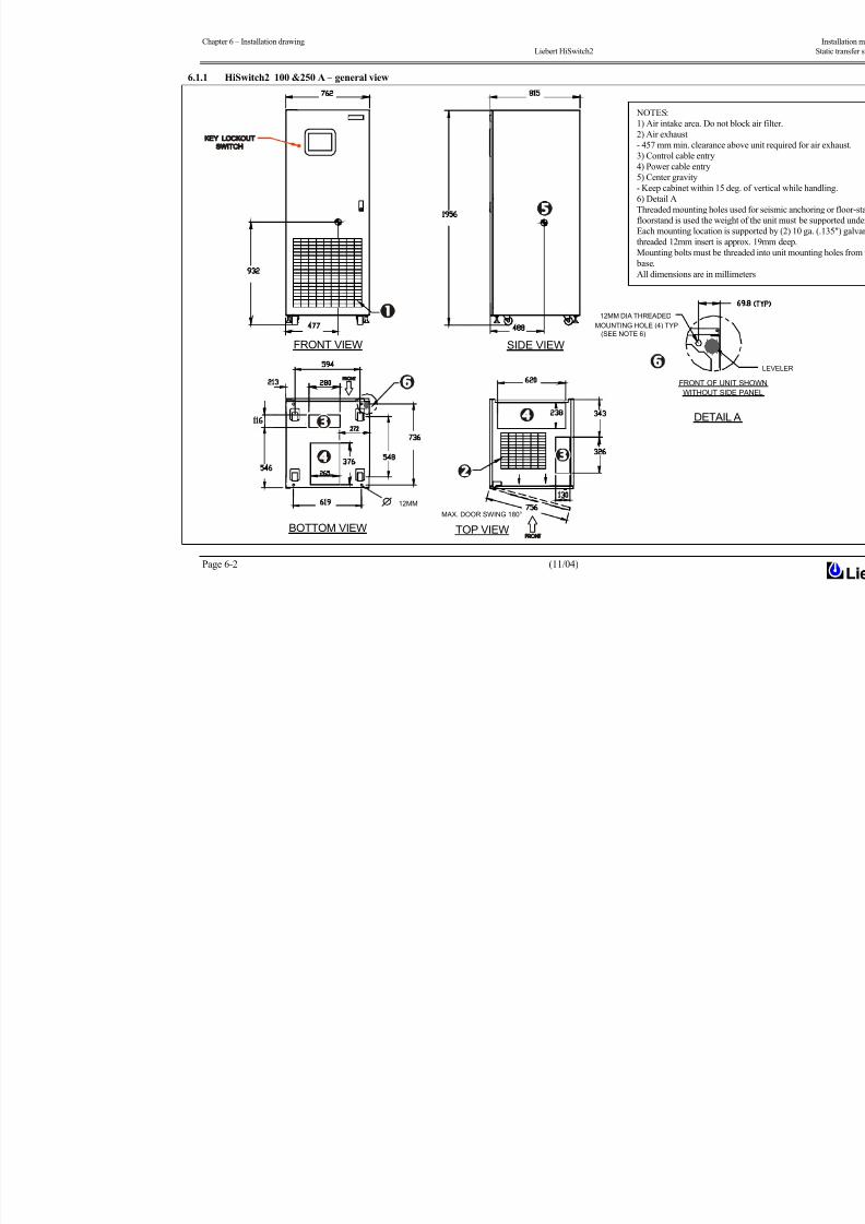
8/11/2019 HiSwitch 2
http://slidepdf.com/reader/full/hiswitch-2 48/112
Chapter 6 – Installation drawing
Liebert HiSwitch2
Page 6-2 (11/04)
6.1.1 HiSwitch2 100 &250 A – general view
NOTES:
1) Air intake area. Do not bl
2) Air exhaust
- 457 mm min. clearance ab
3) Control cable entry
4) Power cable entry
5) Center gravity
- Keep cabinet within 15 deg
6) Detail A
Threaded mounting holes us
floorstand is used the weigh
Each mounting location is su
threaded 12mm insert is app
Mounting bolts must be thre
base.
All dimensions are in millim
SIDE VIEW
TOP VIEWBOTTOM VIEW
FRONT VIEW
MAX. DOOR SWING 180°
12MM
DETAIL A
WITHOUT SIDE
FRONT OF UNIT
(SEE NOTE 6)
12MM DIA THREADED
MOUNTING HOLE (4) TYP
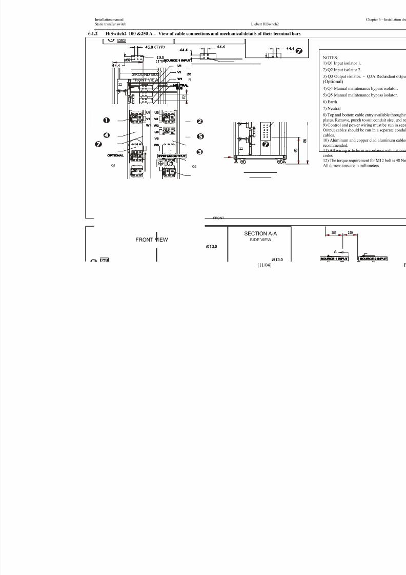
8/11/2019 HiSwitch 2
http://slidepdf.com/reader/full/hiswitch-2 49/112
Installation manual
Static transfer switch Liebert HiSwitch2
(11/04)
6.1.2 HiSwitch2 100 &250 A – View of cable connections and mechanical details of their terminal bars
NOTES:
1) Q1 Input i
2) Q2 Input i3) Q3 Output
(Optional)
4) Q4 Manua
5) Q5 Manua
6) Earth
7) Neutral
8) Top and bo
plates. Remov
9) Control an
Output cables
cables.
10) Aluminumrecommended
11) All wiring
codes.
12) The torqu
All dimension
GROUND
BUS
Q3
GROUND BUS
FRONT VIEW
RIGHT SIDE VIEW
NEUTRAL BUS
RIGHT SIDE VIEW
INPUT/OUTPUT BUS
BUS
FRONT VIEW(WITH FRONT PANELS REMOVED)
SECTION A-A
FRONT
NEUTRAL
Q3A
Q4
Q1
Q5
Q2
SIDE VIEW

8/11/2019 HiSwitch 2
http://slidepdf.com/reader/full/hiswitch-2 50/112
Chapter 6 – Installation drawing
Liebert HiSwitch2
Page 6-4 (11/04)
6.1.3 HiSwitch2 400 &600 A – general view
NOTES:
1) Air intake area. Do n
2) Air exhaust
- 457 mm min. clearanc
3) Control cable entry
4) Power cable entry
5) Center gravity
- Keep cabinet within 15
6) Detail A
Threaded mounting hole
floorstand is used the we
Each mounting location
threaded 12mm insert is
Mounting bolts must be
base.
All dimensions are in m
DETAIL A
WITHOUT SIDE PAN
FRONT OF UNIT SHO
MOUNTING HOLE (4) TYP(SEE NOTES 6)
12MM DIA THREADED
KEY LOCKOUT SWITCH
FRONT VIEW SIDE VIEW
BOTTOM VIEW
TOP VIEWFRONT
MAX. DOOR SWING 180° (TYP)
12MM

8/11/2019 HiSwitch 2
http://slidepdf.com/reader/full/hiswitch-2 51/112
Installation manual
Static transfer switch Liebert HiSwitch2
(11/04)
6.1.4 HiSwitch2 400 &600 A – View of cable connections and mechanical details of their terminal bars
NOTES:
1) Q1 Input i2) Q2 Input i
3) Q3 Output
(Optional)
4) Q4 Manua
5) Q5 Manua
6) Earth
7) Neutral
8) Top and bo
plates. Remov
9) Control an
Output cables
cables.10) Aluminum
recommended
11) All wiring
codes.
12) The torqu
All dimension
Q2
NEUTRALBUS
Q5
Q1
GROUND BUS
FRONT VIEW
RIGHT SIDE VIEW
NEUTRAL BUS
RIGHT SIDE VIEW
INPUT/OUTPUT BUS
(WITH FRONT PANELS REMOVED)
FRONT VIEW
SIDE VIEW
SECTION A-A
Q3
Q4
BUS
GROUND
FRONT
NEUTRAL BUS
Q3A

8/11/2019 HiSwitch 2
http://slidepdf.com/reader/full/hiswitch-2 52/112
Chapter 6 – Installation drawing
Liebert HiSwitch2
Page 6-6 (11/04)
6.1.5 HiSwitch2 800 &1000 A – general view
NOTES:
1) Air intake area. Do not
2) Air exhaust
- 457 mm min. clearance a
3) Control cable entry
4) Power cable entry5) Center gravity
- Keep cabinet within 15 d
6) Detail A
Threaded mounting holes
floorstand is used the weig
Each mounting location is
threaded 12mm insert is ap
Mounting bolts must be th
base.
All dimensions are in mill
FRONT VIEW
CABINET
SIDE VIEW
FRONT
FRONT
KEYLOCKOUT
SWITCH
TOP VIEWBOTTOM VIEW MAX. DOOR SWING 180° (TYP)12MM
BREAKER
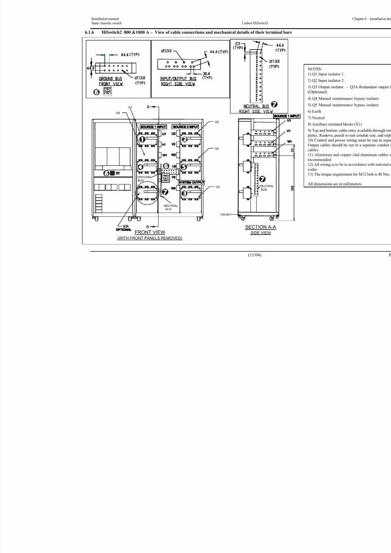
8/11/2019 HiSwitch 2
http://slidepdf.com/reader/full/hiswitch-2 53/112
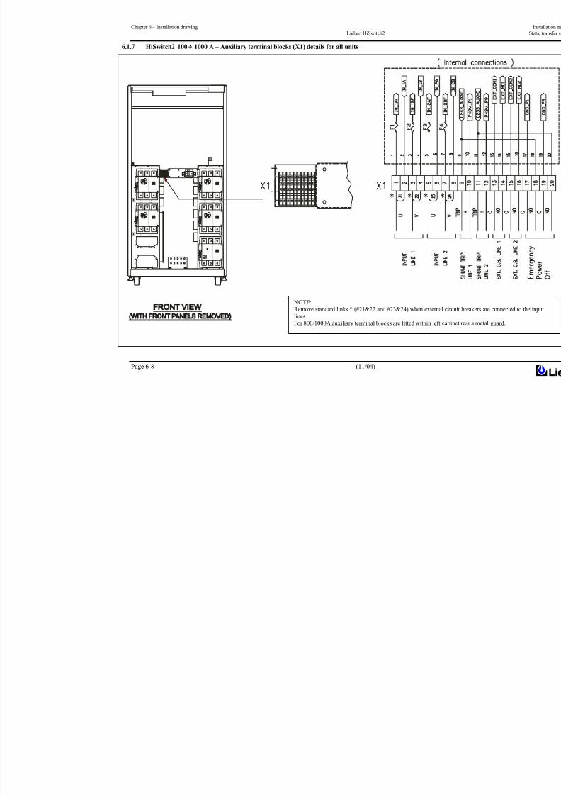
8/11/2019 HiSwitch 2
http://slidepdf.com/reader/full/hiswitch-2 54/112
Chapter 6 – Installation drawing
Liebert HiSwitch2
Page 6-8 (11/04)
6.1.7 HiSwitch2 100 1000 A – Auxiliary terminal blocks (X1) details for all units
NOTE:
Remove standard links * (#21&22 and #23&24) when external circuit breake
lines.
For 800/1000A auxiliary terminal blocks are fitted within left cabinet rear a m
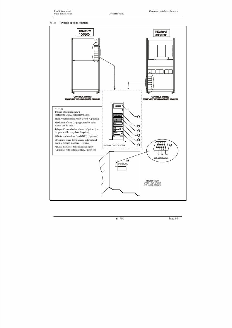
8/11/2019 HiSwitch 2
http://slidepdf.com/reader/full/hiswitch-2 55/112
Installation manual Chapter 6 – Installation drawings
Static transfer switch Liebert HiSwitch2
(11/04) Page 6-9
6.1.8 Typical options location
OPTION LOCATION DETAIL
FRONT VIEWUPPER HALF OF UNIT
WITH DOOR OPENED
1 2 3 4 5
6 7 8 9
TXD RXD
DB9 CONNECTOR
GND
LED PANEL (std)LCD DISPLAY (opt)
NOTES:
Typical options are shown.
1) Remote Source select (Optional)
2&3) Programmable Relay Board (Optional)
Maximum of two (2) programmable relay
boards can be used.
4) Input Contact Isolator board (Optional) or
programmable relay board (option)
5) Network Interface Card (NIC) (Optional)
6) Comms board for Sitescan, external and
internal modem interface (Optional)
7) LED display or touch screen display
(Optional) with a standard RS232 port (8)

8/11/2019 HiSwitch 2
http://slidepdf.com/reader/full/hiswitch-2 56/112
Chapter 6 – Installation drawings Installation manual
Liebert HiSwitch2 Static transfer switch
Page 6-10 (11/04)
6.1.9 Electrical connections in the HiSwitch2
Note 1: (*) Remove standard links (*) when external circuit breakers are connected to the input lines.
Note 2: The neutral connection (N1/N2) is optional. See Note *- page 1-1.

8/11/2019 HiSwitch 2
http://slidepdf.com/reader/full/hiswitch-2 57/112
Installation manual Chapter 6 – Installation drawings
Static transfer switch Liebert HiSwitch2
(11/04) Page 6-11
6.1.10 Location of keys in HiSwitch2 power switch locks
Type Description of function
Single lock
10(X) and 20(Y)
• To turn switch, turn key clockwise.
• To remove key, set switch in the OFF position and turn key anti-clockwise.
• You can release the lock when the key has been removed from the lock (along with
common key 30Z) of the Bypass Switch requiring maintenance work.
Double lock
• To turn on the Bypass Switch requiring maintenance, insert both keys (30Z and either 10X
or 20Y) and turn them clockwise.
• To remove a key, set the switch to the OFF position and turn the key to be removed anti-
clockwise.
OUTPUT
BOLT
BOLT
BOLT
BOLT
10X
20Y
30Z
20Y
10X
30Z
Keys supplied
inserted in locks
8/11/2019 HiSwitch 2
http://slidepdf.com/reader/full/hiswitch-2 58/112
Chapter 6 – Installation drawings Installation manual
Liebert HiSwitch2 Static transfer switch
Page 6-12 (11/04)
This page is left blank intentionally
8/11/2019 HiSwitch 2
http://slidepdf.com/reader/full/hiswitch-2 59/112
User’s Manual Chapter 7 – General Description
Static transfer switch Liebert HiSwitch2 Principles of operation
(11/04) Page 7-1
Part II User’s Manual
7 Chapter 7 – General Description
7.1 IntroductionThe HiSwitch2 contains all the equipment necessary to prevent an interruption in power flow to the AC load, should
your primary source fail.
7.1.1 System Description
A HiSwitch2 provides an automatic, seamless transfer between input power sources to an output load. The HiSwitch2
monitors the input sources, to ensure each source is operating within set parameters, as well as ensure that each source
is within acceptable tolerances for a transfer between sources to be completed.
The HiSwitch2 contains two static transfer switches in one enclosure to allow the unit to transfer its load between the
two input sources without disruption to the output for longer than 1/4 cycle.
If a problem is detected with a primary (Preferred) input source and defined trigger points are reached, the HiSwitch2
automatically switches the input to the other (Alternate) input source. The HiSwitch2 continues to monitor both sources
and can automatically transfer the load back to the preferred source, if so configured, when that source returns to
acceptable operating parameters.The system control logic automatically monitors the input sources and power output to ensure that they are operating
within acceptable tolerances. The system logic manages the transfer between sources.
All control and logic components are mounted separate from the power components. The HiSwitch2 is designed to
minimize the exposure of hazardous voltages to allow safe servicing of the unit while the load is energized.
The HiSwitch2 front panel can be equipped with either a LED display or a Color Graphical Display on LCD touch
screen (Option).
On LED Display units, the RS-232 interface is used for configuration and status and event log monitoring.
In units not equipped with the touch screen, LEDs provide the user with the ability to monitor the HiSwitch2 and
quickly assess problems.
The Color Graphical Display provides a menu-driven operator interface, and a display of system information, status
information, a one-line diagram (Mimic) of the HiSwitch2, active alarms, and alarm history information.
The menu selections provide control of the preferred source, manual transfer initiation. Buttons provide for audiblealarm silence and reset.
Through the touch screen, specific voltage, current and environmental parameters can be configured to trigger events
that can sound an alarm, write to a history log and either transfer sources or inhibit a transfer.
Preferred input source selection, alarm reset and alarm silencing are done through buttons on the touch screen, or push
buttons with the LED display.
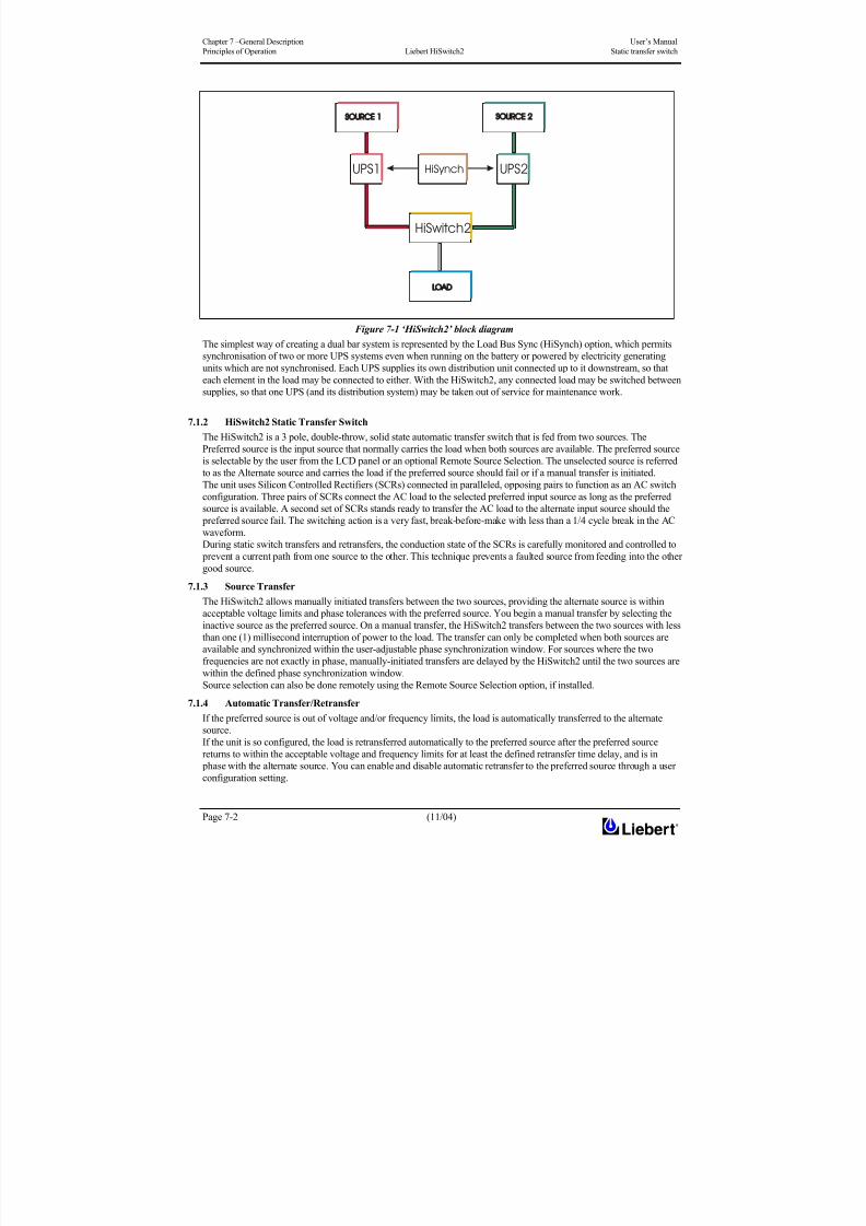
8/11/2019 HiSwitch 2
http://slidepdf.com/reader/full/hiswitch-2 60/112

8/11/2019 HiSwitch 2
http://slidepdf.com/reader/full/hiswitch-2 61/112
User’s Manual Chapter 7 – General Description
Static transfer switch Liebert HiSwitch2 Principles of operation
(11/04) Page 7-3
7.1.4.1 Automatic Retransfer Inhibited
If the system makes five transfers from the preferred source to the alternate source in a five minute period, automatic
retransfers back to the preferred source is disabled.
To clear this alarm condition, you must assign the alternate source as the preferred source.
Also, the UV detection thresholds may need adjustment. See Chapter 11 ‘Source Set Points’ for instructions on setting
the UV detection.
This alarm also is cleared if the unit transfers to the preferred source due to an alternate source AC volt failure (i.e., anemergency transfer.).
7.1.5 Emergency Transfer
To ensure that power remains connected to the load, the HiSwitch2 automatically performs an emergency transfer from
one input source to the other when an outage occurs on the existing source.
The automatic transfer takes place if the other source’s voltage is within acceptable limits, and regardless of the phase
difference between the two sources.
Emergency transfers occur with a loss of power on the output of less than 4 ms.
Emergency transfers from the alternate source to the preferred source are not affected by the Auto Retransfer
Enabled/Disabled or Retransfer Delay user settings.
7.1.6 Load Current Transfer Inhibit
The HiSwitch2 senses the load current. If the load current exceeds the preset level deemed to represent a load inrush orfault condition, the unit’s logic disables manual and automatic transfers, even if the selected source’s input voltage is
outside the acceptable limits. This event triggers an I-Peak alarm. If so configured, the Load Current Transfer Inhibit is
automatically reset after the current and voltage return to within normal parameters. This reset provides continued
protection against a source failure. The Load Current Transfer Inhibit also can be programmed to require a manual
reset. See Chapter 11 ‘Source Set Points’ for details.
7.1.7 SCR Failure
The HiSwitch2 continuously monitors the status of the SCR switching devices for proper operation. In the event of a
shorted SCR on the input source powering the load, the HiSwitch2 automatically triggers an alarm and trips open the
coil of the external input switch. Because the power breakers inside the HiSwitch2 are not automatic, customer must
install external circuit breakers with release coils for isolating the input lines. Refer to figure 2-1.
In the event of an open SCR, the switch automatically triggers an alarm and transfers the load to the other source. All
open and shorted SCR alarm conditions are latched and require the system to be repaired and reset to restore normaloperation.
7.1.8 On/Off Sequence
The HiSwitch2 contains no master On/Off push button control. When connected to the input sources, the unit’s logic
power comes on automatically. The touch screen display (if so equipped) is active as long as at least one input source is
energized and the Control Power Disconnect (located inside the static switch) is on.
7.1.9 Redundancy
Redundancy within the HiSwitch2 prevents one component from being a single point of failure, should a problem
occur. Redundant circuits and components are used to eliminate single points of failure.
Since the HiSwitch2 has two input sources, no single component failure can cause a loss of power to the load.
Redundant power supplies are provided which feed a DC dual-bus used throughout the unit to prevent any single-point
power supply failure modes.Three separate redundant control logic modules are built into the system. Each contains the logic necessary to run the
HiSwitch2, and control all transfers.
Redundant fans are provided if a primary fan fails. The redundant fans turn on to prevent overheating inside of the unit.
Should the front panel interface fail, either touch screen or LEDs, the control logic continues to operate and the unit
would transfer should a problem be detected on the preferred source. Information on the monitoring parameters would
be available through the remote communication options, if available, or the DB9 (RS-232) connector located next to the
LCD display behind the front door.
7.1.10 Emergency stop button
The HiSwitch2 cabinet has no internal emergency stop button.
The ‘normally open’ contacts on the Emergency Stop button outside the HiSwitch2 cabinet must be included in a
specific electric circuit in order to start an external action (such as tripping of an external circuit breaker located on each
of the power sources) to permit complete isolation of the static transfer switch under certain emergency conditions.
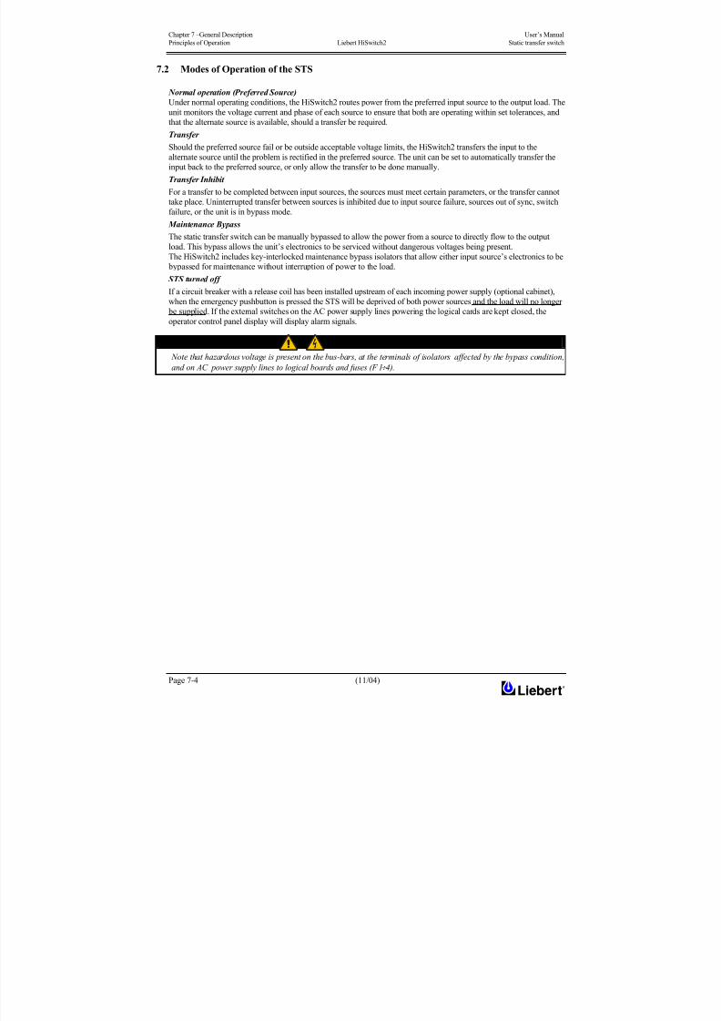
8/11/2019 HiSwitch 2
http://slidepdf.com/reader/full/hiswitch-2 62/112
Chapter 7 –General Description User’s Manual
Principles of Operation Liebert HiSwitch2 Static transfer switch
Page 7-4 (11/04)
7.2 Modes of Operation of the STS
Normal operation (Preferred Source)
Under normal operating conditions, the HiSwitch2 routes power from the preferred input source to the output load. The
unit monitors the voltage current and phase of each source to ensure that both are operating within set tolerances, and
that the alternate source is available, should a transfer be required.Transfer
Should the preferred source fail or be outside acceptable voltage limits, the HiSwitch2 transfers the input to the
alternate source until the problem is rectified in the preferred source. The unit can be set to automatically transfer the
input back to the preferred source, or only allow the transfer to be done manually.
Transfer Inhibit
For a transfer to be completed between input sources, the sources must meet certain parameters, or the transfer cannot
take place. Uninterrupted transfer between sources is inhibited due to input source failure, sources out of sync, switch
failure, or the unit is in bypass mode.
Maintenance Bypass
The static transfer switch can be manually bypassed to allow the power from a source to directly flow to the output
load. This bypass allows the unit’s electronics to be serviced without dangerous voltages being present.
The HiSwitch2 includes key-interlocked maintenance bypass isolators that allow either input source’s electronics to be
bypassed for maintenance without interruption of power to the load.
STS turned off
If a circuit breaker with a release coil has been installed upstream of each incoming power supply (optional cabinet),
when the emergency pushbutton is pressed the STS will be deprived of both power sources and the load will no longer
be supplied. If the external switches on the AC power supply lines powering the logical cards are kept closed, the
operator control panel display will display alarm signals.
WARNING
Note that hazardous voltage is present on the bus-bars, at the terminals of isolators affected by the bypass condition,
and on AC power supply lines to logical boards and fuses (F 1÷ 4).

8/11/2019 HiSwitch 2
http://slidepdf.com/reader/full/hiswitch-2 63/112

8/11/2019 HiSwitch 2
http://slidepdf.com/reader/full/hiswitch-2 64/112
Chapter 7 –General Description User’s Manual
Principles of Operation Liebert HiSwitch2 Static transfer switch
Page 7-6 (11/04)
7.2.2 Typical HiSwitch2 configuration in a dual-bus power supply system
The example in figure 7-3 illustrates ‘dual bus’ wiring. The load with a single input is supplied by a static transfer
switch, which takes the power required from the output of a UPS system. The two UPS systems are synchronised with
the ‘HiSynch’ option.
Figure 7-3 Typical HiSwitch2 configuration in a dual-bus power supply system
HISWITCH2
HISWITCH2

8/11/2019 HiSwitch 2
http://slidepdf.com/reader/full/hiswitch-2 65/112
User’s Manual Chapter 8– Operating the Led front panel
Static transfer switch Liebert HiSwitch2
(11/04) Page 8-1
8 Chapter 8 – Operating the Led front panel
8.1 Introduction
The HiSwitch2 front panel can be equipped with either a LED display or a Color Graphical Display on LCD touch
screen (Option).
The LED front panel allows you to monitor the unit and alert you when a problem occurs.The Color Graphical Display unit is designed to provide all of the information required or to configure and monitor the
unit’s operation.
Both units can be accessed from a terminal, or a PC running terminal emulation software, that is attached to the unit.
Through the RS-232 access, you can monitor and configure the unit, plus remotely select a preferred source. See
Chapter 4 - Using the RS-232 Port for instructions on using the RS-232 interface.
The LED front panel can be replaced with the Color Graphical Display, if desired. Instructions for using the LCD are in
Chapter 11.
8.2 LEDs and Buttons and Key Lockout Switch
The LED Display unit is monitored and controlled through a series of LEDs and buttons and a standard key lockout
switch. This section includes illustrations of the LEDs, buttons and key lockout switch, plus tables providing definitions
of these components.
8.2.1 Front Panel Controls
The front panel contains the LEDs to monitor the HiSwitch2, plus selection buttons to chose the preferred source.
Table 8-1 defines the LEDs and Table 8-2 defines the push-buttons on the unit. Figure below provides a breakdown of
the front panel.
8.2.2 Event Controls
When an alarm is triggered, a red LED is lit in the control panel. A pair of buttons allows you to turn off the horn and
reset the alarm.
Figure 8-1 LED front panel
1 SW_PREF1
2 SW_PREF2
3 ALRMRST
4 NOAUD5 ALRM
8/11/2019 HiSwitch 2
http://slidepdf.com/reader/full/hiswitch-2 66/112
Chapter 8– Operating the Led front panel User’s Manual
Liebert HiSwitch2 Static transfer switch
Page 8-2 (11/04)
8.2.3 LED Definitions
The following table defines what item that these LEDs monitor:
LED Item Monitored Action
1 IN1A Source 1 input present
A green LED is lit if the Source 1 input power is present. This LED
only indicates that power is present to the power supply; it does notindicate if the power is within the programmed tolerances of the
unit.
2 IN2A Source 2 input present
A green LED is lit if the Source 2 input power is present. This LED
only indicates that power is present to the power supply; it does not
indicate if the power is within the programmed tolerances of the
unit.
3 CB1 (Q1) Isolator 1A green LED is lit if Q1 (Input isolator 1) is closed, indicating
power is flowing to the static transfer switch from Source 1.
4 CB2 (Q2) Isolator 2A green LED is lit if Q2 (Input isolator 2) is closed, indicating
power is flowing to the static transfer switch from Source 2.
5 IN1B Source 1 parameters A green LED is lit if Source 1 power is within the programmedtolerance for all phases.
6 IN2B Source 2 parameters A green LED is lit if Source 2 power is within the programmed
tolerance for all phases.
7 STS1 Source 1 SCRs A green LED is lit when the SCRs for Source 1 are closed.
8 STS2 Source 2 SCRs A green LED is lit when the SCRs for Source 2 are closed.
9 LED_PREF1 Source 1 as the preferred
source
A green LED is lit if the button has been pushed to set Source 1 as
the preferred source.
10 LED_PREF2 Source 2 as the preferred
source
A green LED is lit if the button has been pushed to set Source 2 as
the preferred source.
11 NOXF Transfer inhibited
A yellow (amber) LED is lit when source transfers are inhibited
(locked out) by a hardware condition. Connect a PC terminal to the
HiSwitch2 to locate the exact cause.
See Chapter 4 for PC terminal commands.
12 CB3 (Q3) Isolator 3 A green LED is lit if the output switch is closed.
13 CB3A (Q3A) Isolator 3AA green LED is lit if the output switch is closed. Q3A is installed on
units with dual output isolators.
14 CB4 (Q4) Isolator 4 A yellow LED is lit if the Source 1 bypass switch is closed.
15 CB5 (Q5) Isolator 5 A yellow LED is lit if the Source 2 bypass switch is closed.
16 OUT Power present to
output load
A green LED is lit to indicate that power is present on the output
load.
17 ALRM Alarms
A red LED is lit when an alarm condition is present in the
HiSwitch2.
Connect a PC terminal to the HiSwitch2 to locate the exact cause.
See Chapter 4 for PC terminal commands.
Table 8-1 Table for LEDs definitions .

8/11/2019 HiSwitch 2
http://slidepdf.com/reader/full/hiswitch-2 67/112
User’s Manual Chapter 8– Operating the Led front panel
Static transfer switch Liebert HiSwitch2
(11/04) Page 8-3
Figure 8-2 Front panel LEDs and buttons
8.2.4 Button Definitions
Button Definition Action
SW_PREF1 Source 1 Preferred Push this button to select Source 1 as the preferred source.
SW_PREF2 Source 2 Preferred Push this button to select Source 2 as the preferred source.
ALRMRST Alarm reset
Push this button simultaneously with the NOAUD button to reset an alarm
condition. An alarm can only be reset if the hardware condition permits a
reset.
NOAUD Silence
Push this button to turn off the horn that is sounded for an alarm. This
button does not reset an alarm condition, unless pushed simultaneously with
the ALRMRST button.
Note: A standard key lockout switch is already installed.
Table 8-2 Table for Button definitions.
Key:
1(IN1A)
(CB1)1 (IN1B)
(STS1)
(SW_PREF1)
(LED_PREF1)
(CB3)
3 (OUT)
(CB4)
4
2(IN2A)
(CB2)
2 (IN2B) (STS2)
(SW_PREF2)
(LED_PREF2)
(CB5)
5
(CB3a)
3a
(NOXF)
KEY:1 = Input Source 1
2 = Input Source 2
3 = Output
3a = Output, dual
source
4 = Input source 1
Bypass
5 = Input source 2
Bypass
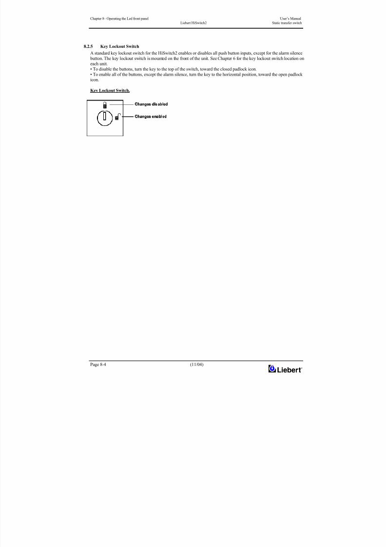
8/11/2019 HiSwitch 2
http://slidepdf.com/reader/full/hiswitch-2 68/112
Chapter 8– Operating the Led front panel User’s Manual
Liebert HiSwitch2 Static transfer switch
Page 8-4 (11/04)
8.2.5 Key Lockout Switch
A standard key lockout switch for the HiSwitch2 enables or disables all push button inputs, except for the alarm silence
button. The key lockout switch is mounted on the front of the unit. See Chapter 6 for the key lockout switch location on
each unit.
• To disable the buttons, turn the key to the top of the switch, toward the closed padlock icon.• To enable all of the buttons, except the alarm silence, turn the key to the horizontal position, toward the open padlock
icon.
Key Lockout Switch.
8/11/2019 HiSwitch 2
http://slidepdf.com/reader/full/hiswitch-2 69/112
8/11/2019 HiSwitch 2
http://slidepdf.com/reader/full/hiswitch-2 70/112
Chapter 9 – Operating Procedures User’s Manual
Liebert HiSwitch2 Static transfer switch
Page 9-2 (11/04)
9.2 Operating instructions
9.2.1 Introduction
The following ‘start-up procedures’ display regular HiSwitch2 start-up procedures after the completion of
commissioning. These instructions must be reconsidered on the basis of:
special or custom modifications made to the equipment, considerations involving the load, special conditions involving
the installation environment or corporate policy requiring modifications to standard equipment start-up procedures.
This section discusses the system turn-on, shut-down and bypass procedures for LED-based HiSwitch2.
Note: These instructions ( ) only refer to the LCD touch screen display (Option).
9.2.2 Normal System Turn-On
This section provides instructions to turn on your HiSwitch2. The LEDs provide the basic information required to
ensure proper operation. To monitor metering data, use a PC terminal.
WARNING
Ensure that the following notice is followed before proceeding with point 1 of the Start-Up procedures:
Close the incoming isolating devices of the input line 1 and 2 that supply the logic boards (refer to table 2-3 ofChapter 2).
1. Ensure that all the isolators of HiSwitch2 are open. Close the incoming external switches connected to the two
inputs of HiSwitch2. Apply power to both HiSwitch2 inputs. The LED display panel is on and working correctly
only when at least one of the two inputs is present.
2. Check that the green LEDs for each source are lit (IN 1A and IN 2A).
( ) The touch screen control panel should become active and operate properly when at least one of the inputs is
energized is closed.
3. Verify that nominal input voltages are applied to both inputs (Source 1 and Source 2).
Check that the green LEDs (IN 1B and IN 2B) monitoring the sources are lit indicating the sources are within
acceptable tolerances.
( ) The input voltages, selected preferred source, breaker and switch status, and alarms are indicated on the Mimic
screen.
Note: Operations involving the input isolators are permitted only after turning the corresponding key
4. Close Q1.
The green LED (CB1) monitoring Q1 turns on.
( ) Verify that Source 1 voltages are nominal and Q1 breaker status is correctly indicated on the Monitor/Mimic
screen.
5. Close Q2.
The green LED (CB2) for Q2 turns on.
( ) Verify that Source 2 voltages are nominal and Q2 isolator status is correctly indicated on the Monitor/Mimic
screen.
6. Verify that the preferred source LED (green) (LED_PREFx) is lit for the source that you want the switch to be
using.
7. Verify that the green LED for the corresponding SCR (STS1 or HiSwitch2) is lit, indicating that the SCR is closed.
( ) Verify that boxes for the preferred source and corresponding static transfer switch are highlighted on the Mimic
screen, indicating which side of the Static Transfer Switch is on.
8. Close Output Isolator Q3 (and Q3A in a redundant output configuration).
9. Verify the Q3 (CB3) LED is lit, indicating that Q3 is closed and the output and load are energized.
• In a redundant output configuration, verify the Q3A (CB3A) LED is lit, indicating that Q3A is closed and the output
and load are energized.
( ) Verify Q3, the Output box, and the Load box are highlighted, indicating that Q3 is closed and the Output and
Load are energized.
10. Press the Alarm Reset (ALRMRST) and Silence (NOAUD) buttons simultaneously to reset any previous alarms.
( ) Press the RESET button on the touch screen to reset any previous alarms.
11. Verify that no red or yellow (amber) LEDs are lit indicating an active alarm, transfer is inhibited or a bypass circuit
isolator is closed.
( ) Verify in the Event Display and the Mimic that there are no active alarms.

8/11/2019 HiSwitch 2
http://slidepdf.com/reader/full/hiswitch-2 71/112
User’s Manual Chapter 9 – Operating Procedures
Static transfer switch Liebert HiSwitch2
(11/04) Page 9-3
If the alarm LED remains lit, check the PC terminal to identify the alarm. Refer to Alarm and Faults on Chapter 10 for a
description of the alarms and possible causes. All active alarm conditions should be corrected before proceeding.
12. Turn on the load equipment following the load equipment manufacturer’s recommendations.
NOTE 1: For redundant output switch units, Q3 descriptions apply to Q3 and Q3A.NOTE 2: If your HiSwitch2 is connected to a PDU with a Wye configuration, enable the Wye Output Transformer
before starting the system. This configuration can be done from a PC terminal. Refer to ‘Using the RS-232 Port’ on
Chapter 4 for instructions.
9.2.3 Manual Transfer / Preferred Source Selection (for LED Display panel)
The preferred source buttons allow you to change the preferred source. Transfers are only permitted when the voltage
and current are within their proper operating range and the sources are synchronized. Transfer is inhibited if the
deviation exceeds the parameter set in the Source Set Points.
NOTE
If one source will be de-energized for an extended period (hours or days), set the unit to bypass mode for the
remaining source. Without using bypass, if a failure occurs in the switch components for remaining source, the HiSwitch2 does not have a second source to switch to and the load would not receive power. See ‘Maintenance
Bypass’ for bypass instructions.
To manually select the preferred source:
1. Ensure that the Transfer Inhibit (NOXF) LED is not lit.
If the Transfer Inhibit LED is lit:
• Check to see if the red alarm LED (ALRM) is lit.
• If the alarm LED is lit, check the alarm messages on a PC terminal.
• Correct alarm conditions before attempting a source transfer.
NOTE 2: When the remote source selection option (Remote Control) is activated, a change of state (Remote Preferred
Source Selection) may initiate a transfer if the appropriate contacts are closed. See Figure 3-1.2. Verify that the LEDs are lit for both sources, indicating power is present and within acceptable tolerances.
3. Verify that the LEDs for the SCRs (STS1 and HiSwitch2) are lit.
4. Verify that the input isolators Q1 and Q2 are closed.
• Verify that their respective LEDs are lit.
5. Push the Preferred Source button for the desired source. See Figure 8-2.
The Preferred Source (LED_PREFx) LED turns on for that source.
When conditions are correct, the switch transfers the load to the alternate source by selecting the alternate source as the
preferred source.
This source is now monitored as the preferred source throughout the various configurations set up through the PC
terminal.
6. Check the LEDs to verify that the correct source is designated as the preferred source and that the input source
changes to the desired source and the output (OUT) LED remains lit.
If your system contains the LCD touch screen display (option) instead of the LED front panel, refer to following
section.
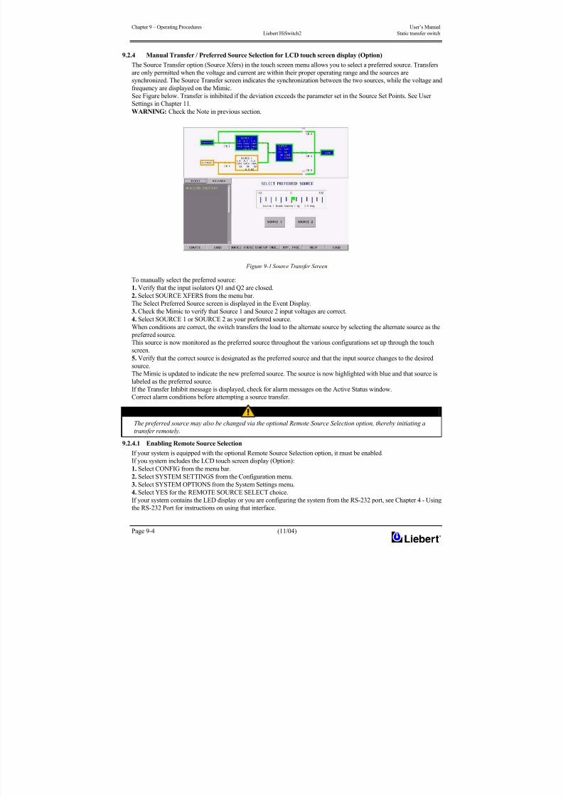
8/11/2019 HiSwitch 2
http://slidepdf.com/reader/full/hiswitch-2 72/112
Chapter 9 – Operating Procedures User’s Manual
Liebert HiSwitch2 Static transfer switch
Page 9-4 (11/04)
9.2.4 Manual Transfer / Preferred Source Selection for LCD touch screen display (Option)
The Source Transfer option (Source Xfers) in the touch screen menu allows you to select a preferred source. Transfers
are only permitted when the voltage and current are within their proper operating range and the sources are
synchronized. The Source Transfer screen indicates the synchronization between the two sources, while the voltage and
frequency are displayed on the Mimic.
See Figure below. Transfer is inhibited if the deviation exceeds the parameter set in the Source Set Points. See UserSettings in Chapter 11.
WARNING: Check the Note in previous section.
Figure 9-1 Source Transfer Screen
To manually select the preferred source:
1. Verify that the input isolators Q1 and Q2 are closed.
2. Select SOURCE XFERS from the menu bar.The Select Preferred Source screen is displayed in the Event Display.
3. Check the Mimic to verify that Source 1 and Source 2 input voltages are correct.
4. Select SOURCE 1 or SOURCE 2 as your preferred source.
When conditions are correct, the switch transfers the load to the alternate source by selecting the alternate source as the
preferred source.
This source is now monitored as the preferred source throughout the various configurations set up through the touch
screen.
5. Verify that the correct source is designated as the preferred source and that the input source changes to the desired
source.
The Mimic is updated to indicate the new preferred source. The source is now highlighted with blue and that source is
labeled as the preferred source.
If the Transfer Inhibit message is displayed, check for alarm messages on the Active Status window.
Correct alarm conditions before attempting a source transfer.
NOTE
The preferred source may also be changed via the optional Remote Source Selection option, thereby initiating a
transfer remotely.
9.2.4.1 Enabling Remote Source Selection
If your system is equipped with the optional Remote Source Selection option, it must be enabled.
If you system includes the LCD touch screen display (Option):
1. Select CONFIG from the menu bar.
2. Select SYSTEM SETTINGS from the Configuration menu.
3. Select SYSTEM OPTIONS from the System Settings menu.
4. Select YES for the REMOTE SOURCE SELECT choice.If your system contains the LED display or you are configuring the system from the RS-232 port, see Chapter 4 - Using
the RS-232 Port for instructions on using that interface.
8/11/2019 HiSwitch 2
http://slidepdf.com/reader/full/hiswitch-2 73/112

8/11/2019 HiSwitch 2
http://slidepdf.com/reader/full/hiswitch-2 74/112
Chapter 9 – Operating Procedures User’s Manual
Liebert HiSwitch2 Static transfer switch
Page 9-6 (11/04)
For convenience, instructions for the bypass procedure can be displayed on the touch screen by selecting the BYP.
PROC option from the menu bar.
The Mimic is used to verify the status of the unit during the bypass procedures. In the unlikely event that the Color
Graphical Display is not available, open the front door and look through the slots in the control door. If you can see
green LEDs on the gate driver board through that slot, then the unit is connected to the source referenced on the label
below that slot. See Figure below.
Figure 9-2 Gate board viewing slot locations
If the LCD display is not available, you can still use the following bypass procedures, ignore the steps to check the
display, and check the LEDs .
Note: These instructions ( ) only refer to the LCD touch screen display (Option).
Bypass Procedures for Source 1
Note: If you wish to bypass the Source 1 static transfer switch but Source 2 is presently active, you must first transfer to
Source 1. See Manual Transfer / Preferred Source Selection in previous section.
If transfer to Source 2 is not desired:
1. Follow the instructions to transfer the load to Source 1, if it is not the currently used source.
( ) Verify Source 1 is supplying power via the Mimic.
• If the LCD Display is not available, check the gate driver board LEDs through the slots in the control panel. SeeFigure 9-2.
2. Remove the interlock key from Q5 and place it in Q4 interlock.
3. Open the alternate source input isolator Q2.
The Q2 LED is turned off.
4. Rotate and remove the interlock key.
5. Insert the key into the Q4 bypass isolator interlock.
6. Rotate interlock keys in the Q4 bypass isolator interlock to retract the interlock.
7. Close bypass isolator Q4.
The LED for Q4 turns on.
( ) Verify the breaker status on the Mimic screen. 8. Open source input isolator Q1.
9. Rotate the interlock key and remove it to lockout the isolator.
The LED for Q1 turns off.( ) Secure the key, per your site’s lockout/tagout procedure.
10. Open the output isolators Q3 and Q3A (if supplied) to remove power from static switch.
TOUCH SCREEN
Viewing Slot for the
Source 2 Gate
Drive Board
Viewing Slot for the
Source 1 Gate
Drive Board
Green leds ON the gate
driver board are
viewable through
this slot indicate that
the STS is on Source
1
Green leds ON the gate driver
board are viewable
through this slot indicate
that the STS is on Source
2
8/11/2019 HiSwitch 2
http://slidepdf.com/reader/full/hiswitch-2 75/112
User’s Manual Chapter 9 – Operating Procedures
Static transfer switch Liebert HiSwitch2
(11/04) Page 9-7
The LEDs for Q3 and Q3A (if supplied) turn off.
11. Verify that the output (OUT) LED is lit.
Power is now flowing directly from the source to the load, without passing through the static transfer switch.
To return to the normal mode:
1. Verify that the LEDs for Source 1 are on, indicating that the source is supplying power and is operating within
acceptable tolerances.
2. Remove the key from Q5 and insert it in the Q1 isolator interlock.
3. Rotate key to retract interlock.
4. Close source input isolator Q1.
The LED for Q1 turns on.
( ) Verify the Source 1 and Q1 isolator status on the Mimic screen. 5. Close the output isolators Q3 and Q3A (if supplied).
The LEDs for Q3 and Q3A are lit.
( ) Verify Q3 and Q3A isolator status and STS SOURCE 1 and OUTPUT boxes are highlighted on the Mimic
screen. 6. Open bypass isolator Q4. Rotate keys in Q4 interlock to extend interlock.
The LED for Q4 is turned off.
7. Remove the proper key from Q4 interlock and insert it into Q2 isolator interlock.
8. Rotate the key to retract Q2 isolator interlock.
9. Close source input isolator Q2.
The LED for Q2 is turned on.
( ) Verify the STS SOURCE 2 box and Q2 isolator status on the Mimic screen.
• If the LCD display is not available, check the gate driver board LEDs through the slots in the control panel. See
Figure 9-2.
10. Verify that the output LED is lit.
Bypass Procedures for Source 2
Note: If you wish to bypass the Source 2 static transfer switch but Source 1 is presently active, you must first transfer toSource 2. See Manual Transfer / Preferred Source Selection in previous section.
If transfer to Source 1 is not desired:
1. Follow the instructions to transfer the load to Source 2, if it is not the currently used source.
( ) Verify Source 2 is supplying power via the Mimic.
• If the LCD Display is not available, check the gate driver board LEDs through the slots in the control panel. See
Figure 9-2.
2. Remove the interlock key from Q4 and place it in Q5 interlock.
The LED for Q1 is turned off.
3. Open the alternate source input isolator Q1.
4. Rotate and remove the interlock key.5. Insert the key into the Q5 bypass isolator interlock and rotate the interlock keys in Q5 bypass isolator interlock to
retract the interlock.
6. Close bypass isolator Q5.
The LED for Q5 is turned on.
( ) Verify the isolator status on the Mimic screen.
7. Open source input isolator Q2.
The LED for Q2 is turned off.
8. Rotate the interlock key and remove it to lockout the isolator.
( ) Secure the key, per your site’s lockout/tagout procedure.
9. Open output isolators Q3 and Q3A (if supplied) to remove power from static switch.
The LEDs for Q3 and Q3A (if supplied) turn off.
10. Verify that the output LED is lit.
Power is now flowing directly from the source to the load, without passing through the static transfer switch.
8/11/2019 HiSwitch 2
http://slidepdf.com/reader/full/hiswitch-2 76/112
Chapter 9 – Operating Procedures User’s Manual
Liebert HiSwitch2 Static transfer switch
Page 9-8 (11/04)
To return to the normal mode:
1. Verify that the LEDs for Source 2 are on, indicating that the source is supplying power and is operating within
acceptable tolerances.
2. Insert key in the Q2 isolator interlock.
3. Rotate key to retract interlock.4. Close source input isolator Q2.
The LED for Q2 is turned on.
( ) Verify Source 2 and Q2 isolator status is supplying power via the Mimic.
5. Close output isolators Q3 and Q3A (if supplied).
The LEDs for Q3 and Q3A (if supplied) turn on.
( ) Verify Q3 and Q3A isolator status and STS SOURCE 2 and OUTPUT boxes are highlighted on the Mimic
screen. 6. Open bypass isolator Q5.
The LED for Q5 is turned off.
7. Rotate keys in Q5 interlock to extend interlock.
8. Remove the proper key from Q5 interlock and insert it in Q1 isolator interlock.
9. Rotate key to retract Q1 isolator interlock.
10. Close source input isolator Q1.
The LED for Q1 is turned on.
( ) Verify the STS SOURCE 1 box and Q1 isolator status on the Mimic screen.
• If the LCD display is not available, check the gate driver board LEDs through the slots in the control panel. See
Figure 9-2.
11. Verify that the output LED is lit.
9.2.6 Normal System Shutdown
The HiSwitch2 can be shut down from either the static switch mode or the bypass mode.
Shutdown in Static Transfer Switch Mode
When the Static Transfer Switch is operating on static transfer switch mode (not maintenance bypass mode):1. Turn off the load equipment per manufacturer’s recommendations.
2. Open Q3 to turn off the static switch output.
• Open Q3A if the static transfer switch is a redundant output configuration.
The LEDs for Q3 and Q3A (if supplied) and the output (OUT) are turned off.
3. Open the input isolators Q1 and Q2.
The LEDs for Q1 and Q2 are turned off.
4. To completely de-energize the unit, turn OFF the power to both inputs to the HiSwitch2.
Shutdown in Maintenance Bypass Mode
When the Static Transfer Switch is operating on bypass:
1. Turn off the load equipment per manufacturer’s recommendations.
2. Open the bypass isolators (Q4 or Q5) to turn off the static transfer switch output.
The LED for the bypass isolators is turned off.
The output (OUT) LED is turned off.
3. To completely de-energize the unit, turn OFF the power to both inputs to the HiSwitch2.
WARNING
To fully isolate the unit, open all external power switches on HiSwitch2 input sources; if this is not done, hazardous voltage
will persist inside the unit (also open knife switches on AC power supply lines powering the logical boards (LINE IN 1-2)).
Post danger signs to prevent inadvertent operations.
8/11/2019 HiSwitch 2
http://slidepdf.com/reader/full/hiswitch-2 77/112
User’s Manual Chapter 10 – Alarm and faults
Static transfer switch Liebert HiSwitch2
(11/04) Page 10-1
10 Chapter 10 – Alarm and faults
10.1 Messages on the display panel
Alarms and faults are events that are triggered when the operation of the static transfer switch falls outside of the
defined parameters. These events can also be triggered by: user actions, such as changing configurations, clearing logs,etc.; failed components such as a fan failure, an SCR that is open or closed, etc.; and system status, such as open circuit
breakers, load on alternate source, etc.
These events can provide a warning or trigger the system to make a change, such as switch sources or the recording of a
history log.
The HiSwitch2 monitoring system detects and annunciates a comprehensive set of fault and alarm conditions.
Faults and alarm messages are can be viewed on the LCD touch screen or via the RS-232 port.
On the LCD touch screen, the events are shown in the Status Display panel in the lower left corner of the touch screen
and written to the Event log. You can touch a message to view a definition of an event and a tip for troubleshooting.
See Touch Screen Display in Chapter 11 for more information on the touch screen.
If you are monitoring the system through the RS-232 port, see Terminal Commands in Chapter 4 for the commands to
view event logs, and alarm and fault lists.
Event actions can be triggered by the settings configured from the Event Masks. See Chapter 11 Event Mask for moreinformation.
Faults — A fault indicates that a component of the HiSwitch2 has failed or has been damaged. In the Event Display,
faults are indicated in red.
Alarms — An alarm is an event caused by a significant abnormal system condition. In the Event Display, alarms are
indicated in yellow. The setpoints for many of the alarms are configurable through the User Settings. Many alarms clear
themselves when the condition is resolved. If an alarm event mask is set to latch, the alarm messages remain active until
the alarm condition has been corrected and the RESET button is pushed. See Event Mask for more information on
latching.
When the system is furnished with an optional internal or external modem and a telephone line is connected to the
modem, the system can be programmed to automatically dial out upon occurrence of any of certain designated alarms.
The auto-dial feature can be configured for alarms using the Event Mask option in the touch screen. See Configuring
the Modem in Chapter 11 for instructions on for setting up your modem.
No alarm signal appears on the operator display panel when the external emergency button is pressed.
10.2 Event mask
The HiSwitch2 gathers, processes and reports faults and alarms, collectively referred to below as events.
The Event Mask dialog box allows you to set the system’s response for specific alarms and faults that are generated.
The following mask types are available for each event:
• Latch — If a latch is enabled for the selected event, that event remains active even if the originating event condition
clears. A latched event may only be cleared by pushing the RESET button (ALRMRST on the LED units).
• Dial Out — If the selected event is triggered, the system automatically calls the specified telephone numbers through
the modem. For example, a page could be sent or an event could be sent to an external terminal, via the modem. SeeChapter 3 for more information on configuring communications options.
• Event Log — The selected event is date/time stamped and recorded to the Event Log when the event is triggered.
• Audible — If the selected event is triggered, an audible beeper or horn is sounded by the HiSwitch2.
The beeper continues while this event is active or latched, or until the SILENCE button (NOAUD on the LED units) is
pushed. This button must be pushed with the ALRMRST button on the LED units.
See Event Masks in Chapter 11 for instructions on setting the mask type via the touch screen display.
See the Setting Event Masks with the Terminal in Chapter 4 for instructions on configuration using the RS-232 port.

8/11/2019 HiSwitch 2
http://slidepdf.com/reader/full/hiswitch-2 78/112
Chapter 10 – Alarm and faults User’s Manual
Liebert HiSwitch2 Static transfer switch
Page 10-2 (11/04)
10.3 Event and History Logs
The system tracks events through the Events Log and tracks significant events through the History Logs. These logs
allow you to quickly spot trends or diagnose problems that the unit may have had. Both logs are written in nonvolatile
memory.
The logs can be accessed from the touch screen menu or the RS-232 port. See Logs in Chapter 11 for more instructions
on viewing the logs from the touch screen. See Terminal Commands in Chapter 4 for the RS-232 interface commandsused to access the logs.
10.3.1 Event Log
The events are tracked in sequence of occurrence. The sequence of occurrence is identified by date, time and frame
number. The last 512 events are stored in a nonvolatile memory and can be viewed from the Event Log.
Event logs wrap, meaning when the log is full, the oldest event is deleted when a new event is written to the log.
The Event Log tracks:
• # — the sequence number in which the event occurred since the log was last cleared.
• Message — the event that occurred, such as Ambient Over temp., Source 1 Fail, etc.
• Type — either a Fault or Alarm. See Alarm and Faults in this chapter for further details on these events.
• ID — the event identifier.
• Date and Time — when the event occurred.
• Faults — the number of fault events logged.• Alarms — the number of alarm events logged.
• User Alarms — the number of alarm events logged that were triggered by user-created alarms, such as those alarms
created with the Input Contact Isolator settings.
• Total — the sum of all the events currently logged.
10.3.2 History Log
When a designated major alarm occurs, the History Status buffer is frozen, capturing 64 sequential frames before and
after the alarm condition. When the History Status buffer is frozen, a History Log is created.
Two History Logs are available to track major alarms. This log includes the triggering event plus the surrounding
events, and the system voltages, currents, frequency, power, source selection and breaker positions at the time of the
event. The History Log displays the 64 sequential frames, in 4-millisecond intervals, of the Present Status screens
surrounding the event.
If you are viewing the log from the touch screen, the Mimic and the Event Display show the data that was present as thealarm was triggered. The data is displayed as frames are played.
The History Log allows you to replay the events leading up to the alarm and the events right after the alarm to see the
status of the switch at that time and diagnose the cause of the alarm. The History Log is triggered when certain events
are tripped that have the Freeze option enabled.
You can run through the frames sequentially. The sequence of the events is identified by date, time, and frame number.
The History Log frames are stored in a nonvolatile memory buffer that is continuously overwritten until a designated
fault condition occurs. When the fault occurs to trigger a freeze, the History Log stores the next 23 frames, then freezes
until it is reset. The History Log then keeps 40 frames before the fault, the frame where the fault occurred, plus the next
23 frames.
The History Log should not be reset until the fault condition that caused the buffer to freeze is reviewed and
investigated by a qualified service technician. After the alarm condition has been corrected, the History Log can be
cleared.
The History Log has the following fields:• Replay Rate — indicates how long it takes for the replay to play. Use the UP and DOWN buttons to set the time.
• Status — the status of the HiSwitch2 at the point of the current frame in the replay. The History log has three statuses:
Frozen, Not Frozen and Retrieving Data, please stand by.
• Critical Event — The event which triggered this log to be written. The event is indicated in red on the bar graph.
• Frame Number — the current frame in the replay. A negative number indicates the replay is at a point before the
triggering event occurred.
10.4 Alarm Notes
The I-PK on Source 1 and I-PK on Source 2 alarms inhibit automatic transfer due to an overload or load fault. These
alarms can be set for either auto or manual alarm reset.
In the auto reset mode, the alarm is reset as soon as the load current and source voltage return to normal, and transfers
are no longer inhibited. In manual mode, the alarm remains active and transfers are inhibited until the conditions return
to normal and the user manually presses the RESET button (ALRMRST button on LED units). In either case, the causeof the Source 1 or Source 2 Ipeak overload should be investigated and resolved (such as by reducing the overload
condition or clearing the output fault) before returning the switch to normal operation.
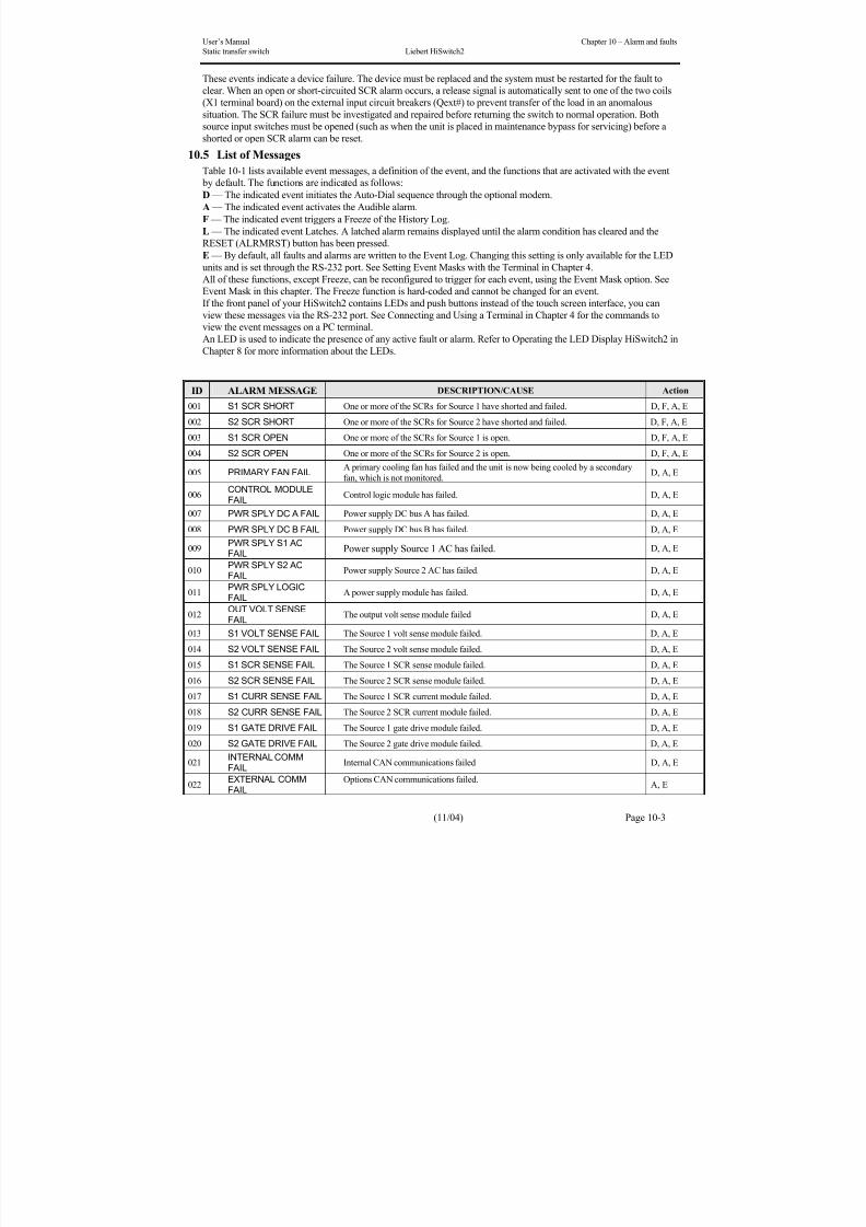
8/11/2019 HiSwitch 2
http://slidepdf.com/reader/full/hiswitch-2 79/112
User’s Manual Chapter 10 – Alarm and faults
Static transfer switch Liebert HiSwitch2
(11/04) Page 10-3
These events indicate a device failure. The device must be replaced and the system must be restarted for the fault to
clear. When an open or short-circuited SCR alarm occurs, a release signal is automatically sent to one of the two coils
(X1 terminal board) on the external input circuit breakers (Qext#) to prevent transfer of the load in an anomalous
situation. The SCR failure must be investigated and repaired before returning the switch to normal operation. Both
source input switches must be opened (such as when the unit is placed in maintenance bypass for servicing) before a
shorted or open SCR alarm can be reset.
10.5 List of Messages
Table 10-1 lists available event messages, a definition of the event, and the functions that are activated with the event
by default. The functions are indicated as follows:
D — The indicated event initiates the Auto-Dial sequence through the optional modem.
A — The indicated event activates the Audible alarm.
F — The indicated event triggers a Freeze of the History Log.
L — The indicated event Latches. A latched alarm remains displayed until the alarm condition has cleared and the
RESET (ALRMRST) button has been pressed.
E — By default, all faults and alarms are written to the Event Log. Changing this setting is only available for the LED
units and is set through the RS-232 port. See Setting Event Masks with the Terminal in Chapter 4.
All of these functions, except Freeze, can be reconfigured to trigger for each event, using the Event Mask option. See
Event Mask in this chapter. The Freeze function is hard-coded and cannot be changed for an event.
If the front panel of your HiSwitch2 contains LEDs and push buttons instead of the touch screen interface, you canview these messages via the RS-232 port. See Connecting and Using a Terminal in Chapter 4 for the commands to
view the event messages on a PC terminal.
An LED is used to indicate the presence of any active fault or alarm. Refer to Operating the LED Display HiSwitch2 in
Chapter 8 for more information about the LEDs.
ID ALARM MESSAGE DESCRIPTION/CAUSE Action
001 S1 SCR SHORT One or more of the SCRs for Source 1 have shorted and failed. D, F, A, E
002 S2 SCR SHORT One or more of the SCRs for Source 2 have shorted and failed. D, F, A, E
003 S1 SCR OPEN One or more of the SCRs for Source 1 is open. D, F, A, E
004 S2 SCR OPEN One or more of the SCRs for Source 2 is open. D, F, A, E
005 PRIMARY FAN FAIL A primary cooling fan has failed and the unit is now being cooled by a secondary
fan, which is not monitored. D, A, E
006CONTROL MODULEFAIL
Control logic module has failed. D, A, E
007 PWR SPLY DC A FAIL Power supply DC bus A has failed. D, A, E
008 PWR SPLY DC B FAIL Power supply DC bus B has failed. D, A, E
009PWR SPLY S1 ACFAIL
Power supply Source 1 AC has failed. D, A, E
010PWR SPLY S2 ACFAIL
Power supply Source 2 AC has failed. D, A, E
011PWR SPLY LOGICFAIL
A power supply module has failed. D, A, E
012 OUT VOLT SENSEFAIL
The output volt sense module failed D, A, E
013 S1 VOLT SENSE FAIL The Source 1 volt sense module failed. D, A, E
014 S2 VOLT SENSE FAIL The Source 2 volt sense module failed. D, A, E
015 S1 SCR SENSE FAIL The Source 1 SCR sense module failed. D, A, E
016 S2 SCR SENSE FAIL The Source 2 SCR sense module failed. D, A, E
017 S1 CURR SENSE FAIL The Source 1 SCR current module failed. D, A, E
018 S2 CURR SENSE FAIL The Source 2 SCR current module failed. D, A, E
019 S1 GATE DRIVE FAIL The Source 1 gate drive module failed. D, A, E
020 S2 GATE DRIVE FAIL The Source 2 gate drive module failed. D, A, E
021 INTERNAL COMMFAIL
Internal CAN communications failed D, A, E
022EXTERNAL COMMFAIL
Options CAN communications failed.A, E

8/11/2019 HiSwitch 2
http://slidepdf.com/reader/full/hiswitch-2 80/112
Chapter 10 – Alarm and faults User’s Manual
Liebert HiSwitch2 Static transfer switch
Page 10-4 (11/04)
ID ALARM MESSAGE DESCRIPTION/CAUSE Action
023CB1 SHUNT TRIPFAIL
Q1 shunt trip failed.A, E
024CB2 SHUNT TRIPFAIL
Q2 shunt trip failed. D, A, E
064HEATSINK
OVERTEMPHeatsink has exceeded the recommended temperature. A, E
067 S1 UV Source 1 under voltage, fast detection. A, E
068 S1 UV (RMS) Source 1 under voltage, slow detection. L, A, E
069 S1 OV Source 1 over voltage A, E
070 S1 OF/UV Source 1 over frequency/under frequency A, E
071 S1 FAIL Source 1 failure A, E
072 S2 UV Source 2 under voltage, fast detection. A, E
073 S2 UV (RMS) Source 2 under voltage, slow detection. A, E
074 S2 OV Source 2 over voltage A, E
075 S2 OF/UV Source 2 over frequency/under frequency A, E
076 S2 FAIL Source 2 failure A, E
077 S1 OVERCURRENT Source 1 over current A, E
078 S2 OVERCURRENT Source 2 over current A, E
079 S1 I-PEAK I-PK on Source 1 A, F, E
080 S2 I-PEAK I-PK on Source 2 A, F, E
081SOURCES OUT OFSYNC
Source 1 and Source 2 are out of synchronization. A, E
082LOAD ON ALTSOURCE
The output load is running on the alternate source. A, E
083 AUTO REXFERINHIBIT
Automatic retransfer is inhibited. A, E
084 CB1 (S1) OPEN Source 1, Isolator 1 (Q1) is open. A, E 085 CB2 (S2) OPEN Source 2, Isolator 2 (Q2) is open. A, E
086CB4 (S1 BYP)CLOSED
Source 1 on bypass, Isolator 4 (Q4) is closed. A, E
087CB5 (S2 BYP)CLOSED
Source 2 on bypass, Isolator 5 (Q5) is closed. A, E
088 CB3 (OUTPUT) OPEN Output Isolator (Q3) is open. A, E
089CB3A (OUTPUT)OPEN
Output Isolator (Q3A) is open. A, E
090S1 PHASE ROTERROR
Source 1 phase rotation error. A, E
091S2 PHASE ROTERROR
Source 2 phase rotation error. A, E
092 TRANSFERINHIBITED
Transfer inhibited. A, E
093 OUTPUT UV Output is under voltage. D, F, A, E
120
121
122
123
124
125
126
127
INPUT CONTACT #1INPUT CONTACT #2INPUT CONTACT #3INPUT CONTACT #4INPUT CONTACT #5INPUT CONTACT #6INPUT CONTACT #7INPUT CONTACT #8
Input Contact # x is an optional alarm input. The alarm name can be programmed
with an alarm name from the Input Contactor Isolator settings option under the
Comm Options.
See Configuring the Input Contact Isolator Settings in Chapter 11. The alarm is
sent to Monitor DSP. The LCD logs the alarm with the programmed name. Monitor
DSP logs it with the generic name, which is how it is reported to the SVT query.
A, E
128 CONFIG MODIFIED A set point configuration has changed. A, E
129PASSWORD
CHANGED The password for touch screen access has been modified and saved. A, E
130TIMEREPROGRAMMED
The system’s time has been reset and saved A, E
131 DATE The system’s date has been reset and saved. A, E
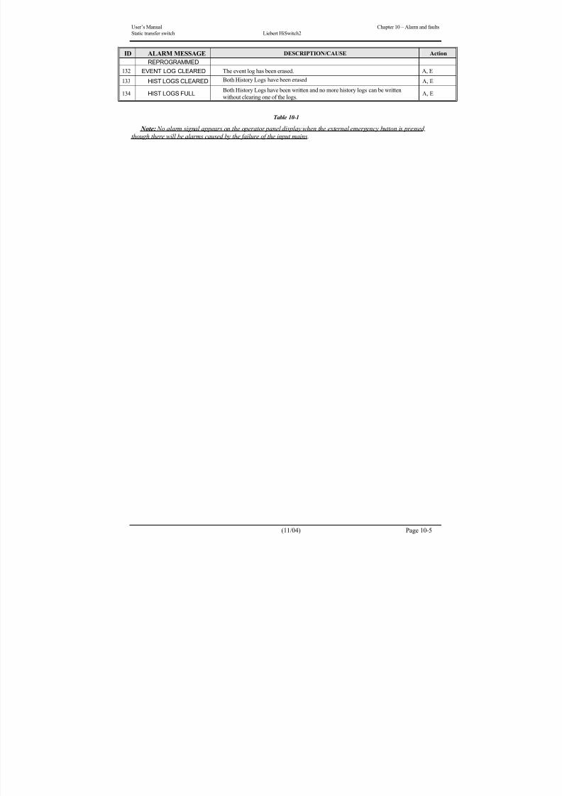
8/11/2019 HiSwitch 2
http://slidepdf.com/reader/full/hiswitch-2 81/112
User’s Manual Chapter 10 – Alarm and faults
Static transfer switch Liebert HiSwitch2
(11/04) Page 10-5
ID ALARM MESSAGE DESCRIPTION/CAUSE Action
REPROGRAMMED
132 EVENT LOG CLEARED The event log has been erased. A, E
133 HIST LOGS CLEARED Both History Logs have been erased A, E
134 HIST LOGS FULL Both History Logs have been written and no more history logs can be written
without clearing one of the logs.
A, E
Table 10-1
Note: No alarm signal appears on the operator panel display when the external emergency button is pressed,
though there will be alarms caused by the failure of the input mains.

8/11/2019 HiSwitch 2
http://slidepdf.com/reader/full/hiswitch-2 82/112
Chapter 11 – Touch Screen Display User’s Manual
Liebert HiSwitch2 Static transfer switch
Page 10-6 (11/04)
This page is left blank intentionally

8/11/2019 HiSwitch 2
http://slidepdf.com/reader/full/hiswitch-2 83/112
User’s Manual Chapter 11 – Touch Screen Display
Static transfer switch Liebert HiSwitch2
(11/04) Page 11-1
11 Chapter 11 – Touch Screen Interface (Option)The HiSwitch2 can be configured with an optional Color Graphical LCD touch screen display that allows you to
quickly check the status of the unit and identify problems.
LCD touch screen display, through the front of the HiSwitch2, provides a graphical (Mimic) display of the switch’s
operation, plus system information including system parameters, alarms and faults.The LCD provides a color, back-lit touch screen as a user interface. In addition to the Mimic and the system
parameters, the screen provides a series of menus to allow you to configure the HiSwitch2, including the control of the
preferred source, auto/manual retransfer selection, alarm notification, and other system setpoints. The touch screen also
provides buttons to reset alarms and turn off audible alarms, such as a horn. A password and a standard keylock are
provided for security.
Figure 11-1 Touch Screen Display panel
11.1 Display Overview
The HiSwitch2 Color Graphical Display provides three areas of information, plus buttons and a series of menu choices.
The Color Graphical Display contains the following features:
• Mimic — a graphical diagram of the status of the unit.
• Event controls — allow you to reset alarms and turn off audible alarms.
• Event Display — displays any active alarm or fault condition, in real-time.• Menus — provide choices and configuration settings in dialog boxes or information in the display panel.
• Display panel — provides additional information, depending on the menu choice that was last selected. This
information includes event help text, and startup and bypass procedures.
Figure 11-2 Touch Screen Display
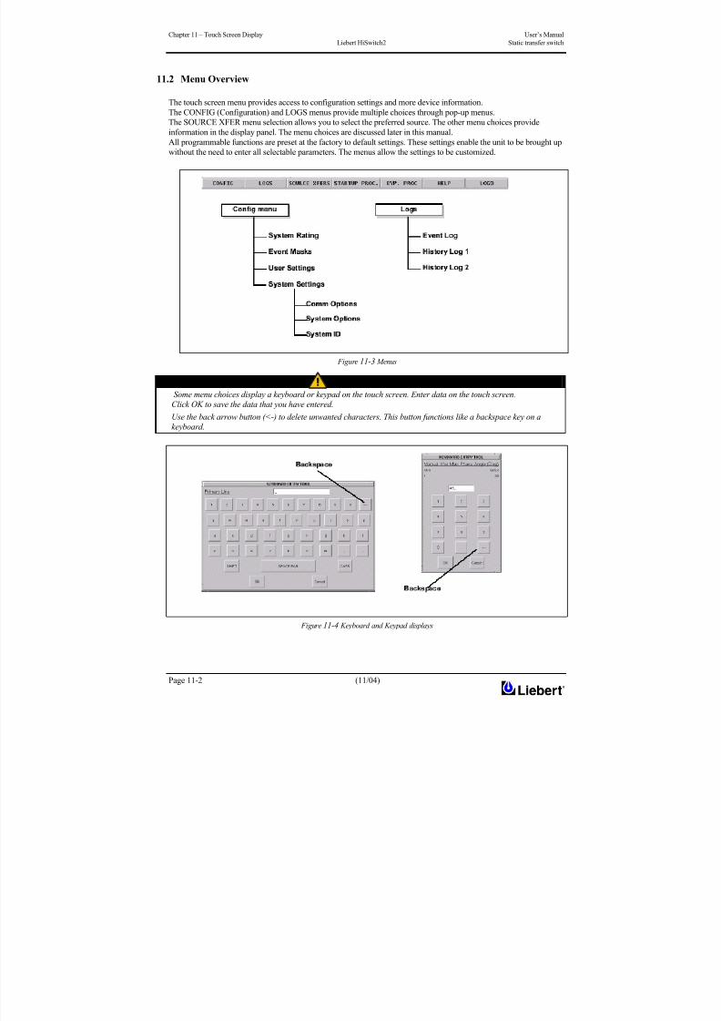
8/11/2019 HiSwitch 2
http://slidepdf.com/reader/full/hiswitch-2 84/112
Chapter 11 – Touch Screen Display User’s Manual
Liebert HiSwitch2 Static transfer switch
Page 11-2 (11/04)
11.2 Menu Overview
The touch screen menu provides access to configuration settings and more device information.
The CONFIG (Configuration) and LOGS menus provide multiple choices through pop-up menus.
The SOURCE XFER menu selection allows you to select the preferred source. The other menu choices provideinformation in the display panel. The menu choices are discussed later in this manual.
All programmable functions are preset at the factory to default settings. These settings enable the unit to be brought up
without the need to enter all selectable parameters. The menus allow the settings to be customized.
Figure 11-3 Menus
NOTE Some menu choices display a keyboard or keypad on the touch screen. Enter data on the touch screen.
Click OK to save the data that you have entered.
Use the back arrow button (<-) to delete unwanted characters. This button functions like a backspace key on a
keyboard.
Figure 11-4 Keyboard and Keypad displays

8/11/2019 HiSwitch 2
http://slidepdf.com/reader/full/hiswitch-2 85/112
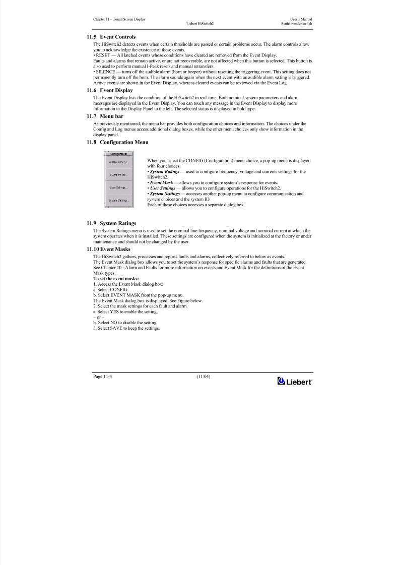
8/11/2019 HiSwitch 2
http://slidepdf.com/reader/full/hiswitch-2 86/112
Chapter 11 – Touch Screen Display User’s Manual
Liebert HiSwitch2 Static transfer switch
Page 11-4 (11/04)
11.5 Event Controls
The HiSwitch2 detects events when certain thresholds are passed or certain problems occur. The alarm controls allow
you to acknowledge the existence of these events.
• RESET — All latched events whose conditions have cleared are removed from the Event Display.
Faults and alarms that remain active, or are not recoverable, are not affected when this button is selected. This button is
also used to perform manual I-Peak resets and manual retransfers.
• SILENCE — turns off the audible alarm (horn or beeper) without resetting the triggering event. This setting does not
permanently turn off the horn. The alarm sounds again when the next event with an audible alarm setting is triggered.
Active events are shown in the Event Display, whereas cleared events can be reviewed via the Event Log.
11.6 Event Display
The Event Display lists the condition of the HiSwitch2 in real-time. Both nominal system parameters and alarm
messages are displayed in the Event Display. You can touch any message in the Event Display to display more
information in the Display Panel to the left. The selected status is displayed in bold type.
11.7 Menu bar
As previously mentioned, the menu bar provides both configuration choices and information. The choices under the
Config and Log menus access additional dialog boxes, while the other menu choices only show information in the
display panel.
11.8 Configuration Menu
When you select the CONFIG (Configuration) menu choice, a pop-up menu is displayed
with four choices.
• System Ratings — used to configure frequency, voltage and currents settings for the
HiSwitch2.
• Event Mask — allows you to configure system’s response for events.
• User Settings — allows you to configure operations for the HiSwitch2.
• System Settings — accesses another pop-up menu to configure communication and
system choices and the system ID.
Each of these choices accesses a separate dialog box.
11.9 System Ratings
The System Ratings menu is used to set the nominal line frequency, nominal voltage and nominal current at which the
system operates when it is installed. These settings are configured when the system is initialized at the factory or under
maintenance and should not be changed by the user.
11.10 Event Masks
The HiSwitch2 gathers, processes and reports faults and alarms, collectively referred to below as events.
The Event Mask dialog box allows you to set the system’s response for specific alarms and faults that are generated.
See Chapter 10 - Alarm and Faults for more information on events and Event Mask for the definitions of the Event
Mask types.
To set the event masks:1. Access the Event Mask dialog box:
a. Select CONFIG.
b. Select EVENT MASK from the pop-up menu.
The Event Mask dialog box is displayed. See Figure below.
2. Select the mask settings for each fault and alarm.
a. Select YES to enable the setting,
– or –
b. Select NO to disable the setting.
3. Select SAVE to keep the settings.

8/11/2019 HiSwitch 2
http://slidepdf.com/reader/full/hiswitch-2 87/112
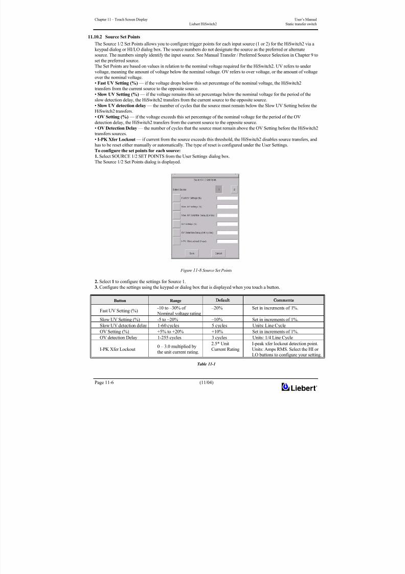
8/11/2019 HiSwitch 2
http://slidepdf.com/reader/full/hiswitch-2 88/112
Chapter 11 – Touch Screen Display User’s Manual
Liebert HiSwitch2 Static transfer switch
Page 11-6 (11/04)
11.10.2 Source Set Points
The Source 1/2 Set Points allows you to configure trigger points for each input source (1 or 2) for the HiSwitch2 via a
keypad dialog or HI/LO dialog box. The source numbers do not designate the source as the preferred or alternate
source. The numbers simply identify the input source. See Manual Transfer / Preferred Source Selection in Chapter 9 to
set the preferred source.
The Set Points are based on values in relation to the nominal voltage required for the HiSwitch2. UV refers to under
voltage, meaning the amount of voltage below the nominal voltage. OV refers to over voltage, or the amount of voltageover the nominal voltage.
• Fast UV Setting (%) — if the voltage drops below this set percentage of the nominal voltage, the HiSwitch2
transfers from the current source to the opposite source.
• Slow UV Setting (%) — if the voltage remains this set percentage below the nominal voltage for the period of the
slow detection delay, the HiSwitch2 transfers from the current source to the opposite source.
• Slow UV detection delay — the number of cycles that the source must remain below the Slow UV Setting before the
HiSwitch2 transfers.
• OV Setting (%) — if the voltage exceeds this set percentage of the nominal voltage for the period of the OV
detection delay, the HiSwitch2 transfers from the current source to the opposite source.
• OV Detection Delay — the number of cycles that the source must remain above the OV Setting before the HiSwitch2
transfers sources.
• I-PK Xfer Lockout — if current from the source exceeds this threshold, the HiSwitch2 disables source transfers, andhas to be reset either manually or automatically. The type of reset is configured under the User Settings.
To configure the set points for each source:
1. Select SOURCE 1/2 SET POINTS from the User Settings dialog box.
The Source 1/2 Set Points dialog is displayed.
Figure 11-8 Source Set Points
2. Select 1 to configure the settings for Source 1.3. Configure the settings using the keypad or dialog box that is displayed when you touch a button.
Button RangeDefault omments
Fast UV Setting (%)-10 to –30% of
Nominal voltage rating
–20% Set in increments of 1%.
Slow UV Setting (%) -5 to –20% –10% Set in increments of 1%.
Slow UV detection delay 1-60 cycles 5 cycles Units: Line Cycle
OV Setting (%) +5% to +20% +10% Set in increments of 1%.
OV detection Delay 1-255 cycles 3 cycles Units: 1/4 Line Cycle
I-PK Xfer Lockout0 – 3.0 multiplied by
the unit current rating.
2.5* Unit
Current Rating
I-peak xfer lockout detection point.
Units: Amps RMS. Select the HI or
LO buttons to configure your setting.
Table 11-1
8/11/2019 HiSwitch 2
http://slidepdf.com/reader/full/hiswitch-2 89/112
User’s Manual Chapter 11 – Touch Screen Display
Static transfer switch Liebert HiSwitch2
(11/04) Page 11-7
4. Select 2 for Source 2.
5. Configure the settings, as described in step 3.
6. Select SAVE to keep the settings for both sources.
The Set Points dialog is closed and the User Settings dialog is displayed.
7. Select MANUAL MAX XFER PHASE ANGLE.A keypad is displayed.
This setting configures the maximum allowed phase difference between the sources and applies to all manual transfers
as well as any auto retransfer.
a. Configure this setting with a range of +/- 1-30 degrees.
The default setting is +/-15 degrees and the resolution is 1 deg.
b. Select OK to save the setting.
The setting is now displayed in the adjacent field in the User Settings dialog box.
8. Select FREQUENCY TRIP POINT.
A keypad is displayed.
This choice verifies that the source is running at the proper frequency. This choice sets the frequency deviation in the
frequency that triggers the frequency trip point alarm. The frequency deviation setting is the allowable frequency
variation from nominal (50.0 or 60.0 Hz) before activating the frequency deviation alarm. The frequency setting applies
to both input sources.
a. Configure this setting with a range of 0.1 – 3.0 Hz
The default setting is 0.5 and the resolution is 0.1.
b. Select OK to save the setting.
9. Select RETRANSFER DELAY.
A keypad is displayed.
With the secondary source being used, this setting sets the length of time the switch waits until attempting to transfer
back to the preferred source.
a. Configure this setting with a range of 1 to 60 seconds.
The default setting is three (3) seconds and the resolution is 1 second.
b. Select OK to save the setting.
The setting is now displayed in the adjacent field in the User Settings dialog box.
10. Select AUDIO LEVEL.A dialog box is displayed with HI and LO settings.
This choice sets the loudness of the horn or beeper that is sounded for audible alarms.
a. Configure this setting with a range of 1–10 (ten).
The default setting is 5. The settings have an increment of 1 (one).
b. Select OK to save the setting.
The setting is now displayed in the adjacent field in the User Settings dialog box.
You can select TEST to briefly sound the alarm to judge its volume.
11. Select DISPLAY BRIGHTNESS.
A dialog box is displayed with HI and LO settings.
This choice sets the brightness for the touch screen.
a. Configure the Contrast and Brightness settings with a range of 1 – 10 (ten).
b. Select OK to save the settings.
12. Set the AUTO REXFER ENABLE choice.The auto retransfer enable setting determines whether the switch automatically returns the preferred source after that
source is restored.
• Select YES to enable the automatic transfer.
• Select NO to disable the automatic transfer. The setting requires transfers be done manually.
13. Set the AUTO RESTART ENABLE choice.
This setting determines whether the HiSwitch2 can be started automatically when power is restored after it has been
lost.
• Select YES to enable the automatic restart.
• Select NO to disable the automatic restart. This setting requires a manual restart of the HiSwitch2.
14. Select a setting for the I-PEAK RESET.
• Select AUTO to configure the static transfer switch to automatically reset when a fault clears and the voltage and
current are normal.
• Select MAN to require a manual reset of the static transfer switch when fault clears and the voltage and current are
normal.

8/11/2019 HiSwitch 2
http://slidepdf.com/reader/full/hiswitch-2 90/112
Chapter 11 – Touch Screen Display User’s Manual
Liebert HiSwitch2 Static transfer switch
Page 11-8 (11/04)
CAUTION
RISK OF EQUIPMENT DAMAGE AND PERSONNEL INJURY.
USE OF AUTO RESTART IS SITE SPECIFIC. DO NOT ENABLE AUTO RESTART UNLESS THE INFRASTRUCTURE IS DESIGNED FOR UNATTENDED OPERATION AND THERE IS NO CHANCE OF EQUIPMENT OR PERSONNEL
HARM BY AUTOMATIC RE-ENERGIZING OF THE SYSTEM.
CONSULT WITH YOUR LIEBERT'S CUSTOMER SERVICE DEPARTMENT AS TO WHETHER AUTO RESTART
SHOULD BE ENABLED.
11.10.3 System Settings
The System Settings choice under the Config menu displays another pop-up menu with three choices:
• Comm Options
• System Options
• System ID
To access the System Settings menu:
1. Select CONFIG from the menu bar.2. Select SYSTEM SETTINGS from the Config menu.
11.10.4 Comm Options
The Comm Options dialog box allows you to configure the communications settings for the HiSwitch2.
• Select COMM OPTIONS from the System Settings Menu.
The Comm Options dialog box is displayed. See Figure below.
• An option can be enabled by selecting YES.
• An option can be disabled by selecting NO.
• An option can be configured by selecting the adjacent option button to display a separate configuration dialog box.
The instructions for configuring the communications options are provided in this section.
Figure 11-9 Comm Options Dialog Box
11.10.5 Configuring the Modem
The Modem dialog box allows you to configure the optional, internal modem or an external modem that is connected to
the static transfer switch. Only one modem can be utilized by the HiSwitch2.
The dialog box contains a series of choices that access either a keypad or a secondary dialog to configure settings. Auto
dial can also be configured for the modem to be triggered by events, as set up in the Event Mask choices.
Designated major alarms activate the auto dial modem sequence. Automatic dial attempts are made to the first number
three times, at 30 seconds between attempts. If connection is not established in that time period, the system
automatically rolls over to the second number. Auto dial attempts are made again three more times at 30 seconds
between attempts. The process is repeated until a successful connection is made. Upon successful connection, the

8/11/2019 HiSwitch 2
http://slidepdf.com/reader/full/hiswitch-2 91/112
User’s Manual Chapter 11 – Touch Screen Display
Static transfer switch Liebert HiSwitch2
(11/04) Page 11-9
system transmits a present status data, including all active alarm messages. After transmission, the modem
automatically hangs up and returns to the auto-answer mode.
To configure the modem:
1. Select MODEM from the Comm Options menu.
The Modem dialog box is displayed.
Figure 11-10 Modem Dialog Box
2. Select the type of modem that the HiSwitch2 will be using:
• Select INT if the HiSwitch2 will be communicating via an internal modem.
• Select EXT if the HiSwitch2 will be communicating via an external modem.
3. Select the PRIMARY LINE choice to enter the primary telephone number for the modem to dial when an alarm is
triggered.
4. Enter the number in the keypad dialog box.
5. Select OK to save the telephone number. The number is displayed in the field adjacent to the Primary Line choice.
6. Select the SECONDARY LINE choice to enter the secondary telephone number for the modem to dial when an
alarm is triggered.
7. Enter the number in the keypad dialog box.
8. Select OK to save the telephone number. The number is displayed in the field adjacent to the Secondary Line choice.
9. Select INIT. STRING to configure the initialization string.
This string configures the parameters of the modem.
• This setting only needs to be configured if an external modem is used. Check your modem’s documentation for
this setting.
• The string for the internal modem set by the manufacturer and does not need to be changed.
10. Select BAUD RATE to display a dialog with the baud rate choices:
• For an external modem, select from 2400 bps, 9600 bps or 19200 bps.
• An internal modem only supports 2400 bps.11. Configure the MODEM HEALTH CHECK.
The Health Check verifies that the modem is working properly. This setting allows you to enable the check and set
when it is run.
a. Select the button to display the Modem Health Check dialog box, from which you can access further dialogs to
set the time and days that the check is run.
b. Select SAVE to keep the settings.
The Health Check dialog box is closed and the Modem dialog box is again active.
c. Select YES in the Modem dialog box to activate the Modem Health Check.
If you select NO, the Modem Health Check is not run.
12. Configure AUTO DIAL IN.
Auto Dial In allows a user to dial into the HiSwitch2 through the modem to check status and access the system via a
hyperterminal connection.
a. Select YES to activate the dial in feature.
b. Select NO to deactivate the dial in feature.
13. Configure AUTO DIAL OUT.

8/11/2019 HiSwitch 2
http://slidepdf.com/reader/full/hiswitch-2 92/112
Chapter 11 – Touch Screen Display User’s Manual
Liebert HiSwitch2 Static transfer switch
Page 11-10 (11/04)
Auto Dial Out allows the HiSwitch2 to automatically dial out to a system to notify a user of an event or status.
a. Select YES to activate the dial out feature.
b. Select NO to deactivate the dial out feature.
14. Select SAVE to keep the modem configuration settings.
15. Select YES in the Comm Options dialog box to activate the settings.
You are returned to the Comm Options dialog box.
11.10.6 Configuring Pager Support
Pager support will be implemented in an upcoming update of the system. This support will trigger the system to call a
pager when specified events occur. This menu choice will allow you to enter the telephone number and PIN for the
pager that you want the system to call.
11.10.7 Configuring the Input Contact Isolator (ICI) settings
The Input Contact Isolator (ICI) is an optional, eight-channel input board for up to eight external user alarm or message
inputs to be routed to the static transfer switch’s alarm network.
The contact is set to either be normally open or normally closed. When a contact closes or opens, an event is triggered.
See Chapter 3 - Input Contact Isolator Board for more information on the ICI.
The Input Contact Isolator options are configured through the Input Contact Isolator dialog box, which is accessed from
the Comm Options dialog box. The Input Contact Isolator dialog box contains eight choices to match the eight channel
input board. You can label each button to identify the event associated with the contact. When the dialog box isaccessed, each button flashes to display the Input Contact Isolator number and the user entered label. This label also
appears in the Display Panel when an event related to an Input Isolator Connector is triggered.
The Input Contact Isolator dialog box allows you to:
• Label the input contact assignments for your setup.
• Set the delay for an external event triggering an alarm.
• Review the isolator contact assignments, once the labels are entered.
The delay allows you to set the number of seconds which a condition needs to persist to trigger an alarm.
These input alarms can also be configured to activate a programmable relay output, which is discussed in Configuring
the Programmable Relay Board Settings in Chapter 3.
To configure the Input Contact Isolator relays:
1. Select INPUT CONTACT ISOLATOR from the Comm Options menu.
The Input Contact Isolator dialog box is displayed.
Figure 11-11 Input contact isolator dialog box
2. Select INPUT CONTACT 1.
A keyboard is displayed to allow you to enter the name of the alarm.
3. Enter the name of the alarm set for that input. For example, a fan problem could be indicated by naming the button
FAN.4. Select OK on the keyboard to keep your label.
5. Select DELAY.
A keypad is displayed prompting you for a delay time, in seconds, for a condition to exist before the alarm is triggered.
8/11/2019 HiSwitch 2
http://slidepdf.com/reader/full/hiswitch-2 93/112
User’s Manual Chapter 11 – Touch Screen Display
Static transfer switch Liebert HiSwitch2
(11/04) Page 11-11
6. Enter the delay value. The range for the values are from 0 (zero) to 99.9 seconds.
7. Select OK on the keypad to keep your setting.
The value you entered is displayed in the field adjacent to the corresponding input contact.
8. Repeat steps 2 to 7 for each input contact.
9. Select SAVE after you have configured all input contacts.
Be sure to select Save even if you have accessed this dialog only to change a setting.
10. Enter the settings in Input Contact Isolator Settings Record at the biginning of this manual.
NOTE
This information is not saved if control power is removed.
11. Select OK in the Comm Options dialog box to activate the settings.
11.10.8 Configuring the Programmable Relay Board Settings
The HiSwitch2 can contain up to two Programmable Relay Boards (PRB) that can trigger an external device when an
event occurs in the static transfer switch. For example, if Source 1 fails, an external light flashes.
See Chapter 3 - Programmable Relay Board for more information on the PRBs.
The Programmable Relay Board dialog box with two options: STANDARD SET and USER DEFINED SET. TheSTANDARD SET are the factory-configured settings.
The STANDARD SET for the Programmable Relay Board settings are:
Relay SettingDefinition
1 SOURCE 1 FAIL Source 1 failure
2 SOURCE 2 FAIL Source 2 failure
3 BYPASS CB4 CLOSED Switch (Q4) is closed, Source 1 is bypassed.
4 BYPASS CB5 CLOSED Switch (Q5) is closed, Source 2 is bypassed.
5 TRANSFER INHIBITA transfer between Source 1 and Source 2 is being
restrained.
6 OUT OF SYNCThe phase difference between sources 1 and 2 exceeds the
allowable threshold for transfer7 EQUIP OVER TEMP
The ambient temperature of the HiSwitch2 exceeds the
recommended threshold for operation.
8 blank No setting.
Table 11-2 Standard Settings for Programmable Relays
The USER DEFINED SET allows you to assign faults and alarms to each contact on the relay boards.
Utilizing the USER DEFINED SET, you can also select Input Contact Isolators to associate with a programmable relay.
In addition individual events, three other assignment choices are available:
• SELECT ALL sends a summary event to the selected relay whenever any event occurs. If this setting is selected
for a relay, no other event needs to be assigned for that relay.
• ON SOURCE 1 or ON SOURCE 2 can be assigned to a relay to send a notification when that source is being used by the load.
Once configured, the static transfer switch continuously checks the status of the items defined for each contact and
updates the state of the relay.
To configure your programmable relay boards for user defined settings:
1. Select PROG. RELAY BOARD # x from the Comm Options dialog box, where x is the corresponding board
number.
The Prog. Relay Board dialog box is displayed.

8/11/2019 HiSwitch 2
http://slidepdf.com/reader/full/hiswitch-2 94/112
Chapter 11 – Touch Screen Display User’s Manual
Liebert HiSwitch2 Static transfer switch
Page 11-12 (11/04)
Figure 11-12 Programmable Relay board dialog box
2. Select your configuration settings.
• Select STANDARD SET to use the settings configured at the factory. See Go to step 4.• Select USER DEFINED SET to configure your own settings. Go to step 3.
NOTE
If you enter a user defined settings, this information is not saved if control power is removed.
Record the settings in Programmable Relay Board Settings Record at the biginning of this manual.
3. To define your relay board settings:
a. Select a Programming Relay.
b. Select an event you want associated with the relay. That fault is placed in the Relay column.
You can associate up to ten (10) events with one relay. If you do so, you should group the events logically to simplify
troubleshooting when an event is triggered.
4. Select SAVE to keep the settings.5. Select OK for the applicable Programmable Options Board option in the Comm Options dialog box to activate the
settings.
11.10.9 Configuring the Network Interface Card
An optional Liebert OpenComms Network Interface Card (NIC) can be installed in the HiSwitch2 to provide Ethernet
connectivity via an RJ-45 port.
Ethernet cabling is the responsibility of the customer. Category 5 cabling is required.
See Chapter 3 - Network Interface Card (NIC) for more information on the NIC.
See the OpenComms Network Interface Card Installation and Users Guide for configuration instructions for the card.
If the optional OpenComm NIC is installed in the HiSwitch2:• Select YES for the Network Interface Card option in the Comm Options dialog box to activate the card.
11.10.10 SiteScan ConfigurationAn optional RS-422 port, contained in the Comms Board, can be installed in the static transfer switch to provide
communications with Liebert’s SiteScan. SiteScan is Liebert’s system monitoring software that allows you to utilize a
PC to monitor the static transfer switch’s status and check alarms. See Chapter 3 - Comms Board for more information
on this board.
If the HiSwitch2 will be connected to SiteScan:• Select YES for the SiteScan choice in the Comm Options dialog box to activate the card.
11.10.11 Saving Your Communications Configurations
To save you communications configuration settings:
1. When you have completed the Comm Options configurations, ensure you have selected YES for all the settings that
you want activated.
2. Select SAVE to keep the settings.
Whenever you make modifications to the any of the Comm Options, select SAVE to keep the changes.
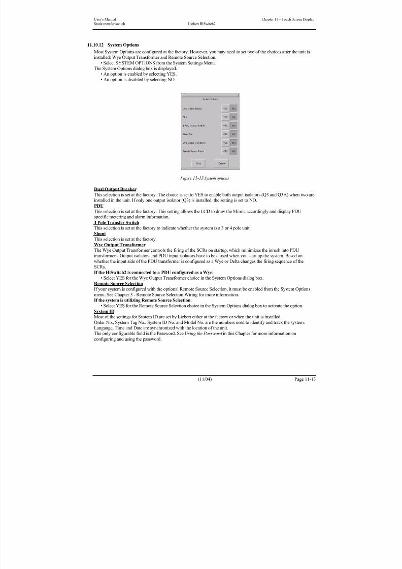
8/11/2019 HiSwitch 2
http://slidepdf.com/reader/full/hiswitch-2 95/112
User’s Manual Chapter 11 – Touch Screen Display
Static transfer switch Liebert HiSwitch2
(11/04) Page 11-13
11.10.12 System Options
Most System Options are configured at the factory. However, you may need to set two of the choices after the unit is
installed: Wye Output Transformer and Remote Source Selection.
• Select SYSTEM OPTIONS from the System Settings Menu.
The System Options dialog box is displayed.• An option is enabled by selecting YES.
• An option is disabled by selecting NO.
Figure 11-13 System options
Dual Output Breaker
This selection is set at the factory. The choice is set to YES to enable both output isolators (Q3 and Q3A) when two are
installed in the unit. If only one output isolator (Q3) is installed, the setting is set to NO.
PDU
This selection is set at the factory. This setting allows the LCD to draw the Mimic accordingly and display PDUspecific metering and alarm information.
4 Pole Transfer Switch
This selection is set at the factory to indicate whether the system is a 3 or 4 pole unit.
ShuntThis selection is set at the factory.
Wye Output TransformerThe Wye Output Transformer controls the firing of the SCRs on startup, which minimizes the inrush into PDU
transformers. Output isolators and PDU input isolators have to be closed when you start up the system. Based on
whether the input side of the PDU transformer is configured as a Wye or Delta changes the firing sequence of the
SCRs.
If the HiSwitch2 is connected to a PDU configured as a Wye:
• Select YES for the Wye Output Transformer choice in the System Options dialog box.
Remote Source Selection
If your system is configured with the optional Remote Source Selection, it must be enabled from the System Options
menu. See Chapter 3 - Remote Source Selection Wiring for more information.
If the system is utilizing Remote Source Selection:• Select YES for the Remote Source Selection choice in the System Options dialog box to activate the option.
System IDMost of the settings for System ID are set by Liebert either at the factory or when the unit is installed.
Order No., System Tag No., System ID No. and Model No. are the numbers used to identify and track the system.
Language, Time and Date are synchronized with the location of the unit.
The only configurable field is the Password. See Using the Password in this Chapter for more information on
configuring and using the password.
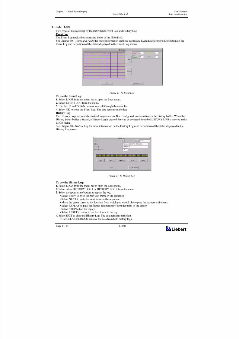
8/11/2019 HiSwitch 2
http://slidepdf.com/reader/full/hiswitch-2 96/112
Chapter 11 – Touch Screen Display User’s Manual
Liebert HiSwitch2 Static transfer switch
Page 11-14 (11/04)
11.10.13 Logs
Two types of logs are kept by the HiSwitch2: Event Log and History Log.
Event Log
The Event Log tracks the alarms and faults of the HiSwitch2.
See Chapter 10 - Alarm and Faults for more information on these events and Event Log for more information on theEvent Log and definitions of the fields displayed in the Event Log screen.
Figure 11-14 Event Log
To use the Event Log:
1. Select LOGS from the menu bar to open the Logs menu.
2. Select EVENT LOG from the menu.
3. Use the UP and DOWN buttons to scroll through the event list.
4. Select OK to close the Event Log. The data remains in the log.
History Log
Two History Logs are available to track major alarms. If so configured, an alarm freezes the history buffer. When the
History Status buffer is frozen, a History Log is created that can be accessed from the HISTORY LOG x choices in the
LOGS menu.
See Chapter 10 - History Log for more information on the History Logs and definitions of the fields displayed in theHistory Log screen.
Figure 11-15 History Log
To use the History Log:
1. Select LOGS from the menu bar to open the Logs menu.
2. Select either HISTORY LOG 1 or HISTORY LOG 2 from the menu.
3. Select the appropriate buttons to replay the log:
• Select PREV to go to the previous frame in the sequence.
• Select NEXT to go to the next frame in the sequence.
• Move the green cursor to the location from which you would like to play the sequence of events.
• Select REPLAY to play the frames automatically from the point of the cursor.
• Select STOP to halt the replay.• Select RESET to return to the first frame in the log.
4. Select EXIT to close the History Log. The data remains in the log.
• Use CLEAR HLOGS to remove the data from both history logs.

8/11/2019 HiSwitch 2
http://slidepdf.com/reader/full/hiswitch-2 97/112
User’s Manual Chapter 11 – Touch Screen Display
Static transfer switch Liebert HiSwitch2
(11/04) Page 11-15
NOTE
Event and History Logs are protected by security. The password or a disabled key lockout is required on such
equipped units to clear these logs.
11.10.14 Source Transfers
The Source Transfer choice (SOURCE XFERS) allows you to manually select a preferred source.
To switch the primary source, refer to the instructions in Manual Transfer / Preferred Source Selection in Chapter 9.
11.10.15 Startup Procedure
You can access instructions for starting the HiSwitch2 from the menu bar.
• From the menu bar, select STARTUP PROC.
These instructions are also provided in Chapter 9 - Normal System Turn-On for Color Graphical display units and for
LED Display units.
11.10.16 Bypass Procedure
You can access instructions for bypassing the static transfer switch from the menu bar.
• From the menu bar, select BYP. PROC.
The instructions are provided in the display panel.
Bypass procedures are also discussed in Chapter 9 - Maintenance Bypass for Color Graphical display units and for
LED Display units.
11.10.17 Help
You can select an event in the Event Display to display more information about that event in the Display Panel. This
same help is also available in next section - Event Message Help Text .
11.10.18 Logo
The Logo menu choice shows the Liebert and Emerson logo in the Display panel.
11.11 Cleaning the LCD Touch Screen
If the touch screen requires cleaning, use a pre-moistened towelette designed for cleaning CRTs, or dampen a soft, non-
abrasive cloth with a very mild cleaning solution.Do not spray the cleaner directly onto the touch screen, as drips may run down into the screen and damage the
equipment.
Close all menus and dialog boxes before cleaning the touch screen.
11.12 Operating instructions for the Touch Screen Interface After the initial equipment start-up, the following operating guidelines can be used for equipment operation.
All programmable functions are preset at the factory to enable the unit to be brought up without the need to enter all
selectable parameters.
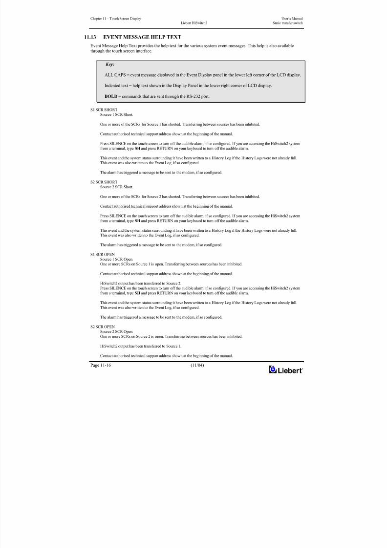
8/11/2019 HiSwitch 2
http://slidepdf.com/reader/full/hiswitch-2 98/112
Chapter 11 – Touch Screen Display User’s Manual
Liebert HiSwitch2 Static transfer switch
Page 11-16 (11/04)
11.13 EVENT MESSAGE HELP TEXT
Event Message Help Text provides the help text for the various system event messages. This help is also available
through the touch screen interface.
S1 SCR SHORT
Source 1 SCR Short.
One or more of the SCRs for Source 1 has shorted. Transferring between sources has been inhibited.
Contact authorised technical support address shown at the beginning of the manual.
Press SILENCE on the touch screen to turn off the audible alarm, if so configured. If you are accessing the HiSwitch2 system
from a terminal, type SH and press RETURN on your keyboard to turn off the audible alarm.
This event and the system status surrounding it have been written to a History Log if the History Logs were not already full.
This event was also written to the Event Log, if so configured.
The alarm has triggered a message to be sent to the modem, if so configured.
S2 SCR SHORT
Source 2 SCR Short.
One or more of the SCRs for Source 2 has shorted. Transferring between sources has been inhibited.
Contact authorised technical support address shown at the beginning of the manual.
Press SILENCE on the touch screen to turn off the audible alarm, if so configured. If you are accessing the HiSwitch2 system
from a terminal, type SH and press RETURN on your keyboard to turn off the audible alarm.
This event and the system status surrounding it have been written to a History Log if the History Logs were not already full.
This event was also written to the Event Log, if so configured.
The alarm has triggered a message to be sent to the modem, if so configured.
S1 SCR OPEN
Source 1 SCR Open.
One or more SCRs on Source 1 is open. Transferring between sources has been inhibited.
Contact authorised technical support address shown at the beginning of the manual.
HiSwitch2 output has been transferred to Source 2.
Press SILENCE on the touch screen to turn off the audible alarm, if so configured. If you are accessing the HiSwitch2 system
from a terminal, type SH and press RETURN on your keyboard to turn off the audible alarm.
This event and the system status surrounding it have been written to a History Log if the History Logs were not already full.
This event was also written to the Event Log, if so configured.
The alarm has triggered a message to be sent to the modem, if so configured.
S2 SCR OPEN
Source 2 SCR Open.
One or more SCRs on Source 2 is open. Transferring between sources has been inhibited.
HiSwitch2 output has been transferred to Source 1.
Contact authorised technical support address shown at the beginning of the manual.
Key:
ALL CAPS = event message displayed in the Event Display panel in the lower left corner of the LCD display.
Indented text = help text shown in the Display Panel in the lower right corner of LCD display.
BOLD = commands that are sent through the RS-232 port.

8/11/2019 HiSwitch 2
http://slidepdf.com/reader/full/hiswitch-2 99/112
User’s Manual Chapter 11 – Touch Screen Display
Static transfer switch Liebert HiSwitch2
(11/04) Page 11-17
Press SILENCE on the touch screen to turn off the audible alarm, if so configured. If you are accessing the HiSwitch2 system
from a terminal, type SH and press RETURN on your keyboard to turn off the audible alarm.
This event and the system status surrounding it have been written to a History Log if the History Logs were not already full.
This event was also written to the Event Log, if so configured.
The alarm has triggered a message to be sent to the modem, if so configured.
PRIMARY FAN FAIL
Primary Fan Failure
One of the primary cooling fans for the HiSwitch2 has failed. The alternate fans are now running. The alternate fans are not
monitored.
Contact authorised technical support address shown at the beginning of the manual.
Press SILENCE on the touch screen to turn off the audible alarm, if so configured. If you are accessing the HiSwitch2 system
from a terminal, type SH and press RETURN on your keyboard to turn off the audible alarm.
This event was written to the Event Log, if so configured.
The alarm has triggered a message to be sent to the modem, if so configured.
CONTROL MODULE FAIL
Control logic module has failed.
One of the control modules on the control board has failed.
Contact authorised technical support address shown at the beginning of the manual.
Press SILENCE on the touch screen to turn off the audible alarm, if so configured. If you are accessing the HiSwitch2 system
from a terminal, type SH and press RETURN on your keyboard to turn off the audible alarm.
This event was written to the Event Log, if so configured.
The alarm has triggered a message to be sent to the modem, if so configured.
If configured to be a latching alarm, press RESET on the display. If you are accessing the unit from a terminal, type CA and
press RETURN on your keyboard.
PWR SPLY DC A FAIL
Power Supply DC Bus A Failed
The primary power supply is no longer providing DC power to the control board and the touch screen.
Contact authorised technical support address shown at the beginning of the manual.
Press SILENCE on the touch screen to turn off the audible alarm, if so configured. If you are accessing the HiSwitch2 systemfrom a terminal, type SH and press RETURN on your keyboard to turn off the audible alarm.
This event was written to the Event Log, if so configured.
The alarm has triggered a message to be sent to the modem, if so configured.
If configured to be a latching alarm, press RESET on the display. If you are accessing the unit from a terminal, type CA and
press RETURN on your keyboard.
PWR SPLY DC B FAIL
Power Supply DC Bus B Failed
The secondary power supply is no longer providing DC power to the control board and CAN options.
Contact authorised technical support address shown at the beginning of the manual.
Press SILENCE on the touch screen to turn off the audible alarm, if so configured. If you are accessing the HiSwitch2 system
from a terminal, type SH and press RETURN on your keyboard to turn off the audible alarm.
This event was written to the Event Log, if so configured.The alarm has triggered a message to be sent to the modem, if so configured.
If configured to be a latching alarm, press RESET on the display. If you are accessing the unit from a terminal, type CA and
press RETURN on your keyboard.
PWR SPLY S1 AC FAIL
Power Supply Source 1 AC Failed
The AC input power to the power supplies from Source 1 has failed. The power supplies are now operating on AC power from
Source 2. The AC input from Source 1 is still good.
Contact authorised technical support address shown at the beginning of the manual.
Press SILENCE on the touch screen to turn off the audible alarm, if so configured. If you are accessing the HiSwitch2 system
from a terminal, type SH and press RETURN on your keyboard to turn off the audible alarm.
This event was written to the Event Log, if so configured.
The alarm has triggered a message to be sent to the modem, if so configured.
If configured to be a latching alarm, press RESET on the display. If you are accessing the unit from a terminal, type CA and press RETURN on your keyboard.

8/11/2019 HiSwitch 2
http://slidepdf.com/reader/full/hiswitch-2 100/112
Chapter 11 – Touch Screen Display User’s Manual
Liebert HiSwitch2 Static transfer switch
Page 11-18 (11/04)
PWR SPLY S2 AC FAIL
Power Supply Source 2 AC Failed
The AC input power to the power supplies from Source 2 has failed. The power supplies are now operating on AC power from
Source 1. The AC input from Source 2 is still good.
Contact authorised technical support address shown at the beginning of the manual.
Press SILENCE on the touch screen to turn off the audible alarm, if so configured. If you are accessing the HiSwitch2 systemfrom a terminal, type SH and press RETURN on your keyboard to turn off the audible alarm.
This event was written to the Event Log, if so configured.
The alarm has triggered a message to be sent to the modem, if so configured.
If configured to be a latching alarm, press RESET on the display. If you are accessing the unit from a terminal, type CA and
press RETURN on your keyboard.
PWR SPLY LOGIC FAIL
Power Supply Module Failed
The power supply logic module contained in the primary power supply has failed.
Contact authorised technical support address shown at the beginning of the manual.
Press SILENCE on the touch screen to turn off the audible alarm, if so configured. If you are accessing the HiSwitch2 system
from a terminal, type SH and press RETURN on your keyboard to turn off the audible alarm.
This event was written to the Event Log, is so configured.
The alarm has triggered a message to be sent to the modem, if so configured.If configured to be a latching alarm, press RESET on the display. If you are accessing the unit from a terminal, type CA and
press RETURN on your keyboard.
OUT VOLT SENSE FAIL
Output Voltage Sense Module Failed
The module contained on the snubber monitoring the output voltage has failed.
Press SILENCE on the touch screen to turn off the audible alarm, if so configured. If you are accessing the HiSwitch2 system
from a terminal, type SH and press RETURN on your keyboard to turn off the audible alarm.
Contact authorised technical support address shown at the beginning of the manual.
This event was written to the Event Log, if so configured.
The alarm has triggered a message to be sent to the modem, if so configured.
If configured to be a latching alarm, press RESET on the display. If you are accessing the unit from a terminal, type CA and
press RETURN on your keyboard.
S1 VOLT SENSE FAIL
Source 1 Voltage Sense Module Failed
The module contained on the snubber monitoring the input voltage from Source 1 has failed.
Press SILENCE on the touch screen to turn off the audible alarm, if so configured. If you are accessing the HiSwitch2 system
from a terminal, type SH and press RETURN on your keyboard to turn off the audible alarm.
Contact authorised technical support address shown at the beginning of the manual.
This event was written to the Event Log, if so configured.
The alarm has triggered a message to be sent to the modem, if so configured.
If configured to be a latching alarm, press RESET on the display. If you are accessing the unit from a terminal, type CA and
press RETURN on your keyboard.
S2 VOLT SENSE FAIL
Source 2 Voltage Sense Module FailedThe module contained on the snubber monitoring the input voltage from Source 2 has failed.
Press SILENCE on the touch screen to turn off the audible alarm, if so configured. If you are accessing the HiSwitch2 system
from a terminal, type SH and press RETURN on your keyboard to turn off the audible alarm.
Contact authorised technical support address shown at the beginning of the manual.
This event was written to the Event Log, if so configured.
The alarm has triggered a message to be sent to the modem, if so configured.
If configured to be a latching alarm, press RESET on the display. If you are accessing the HiSwitch2 system from a terminal,
type CA and press RETURN on your keyboard.
S1 SCR SENSE FAIL
Source 1 SCR Sense Module Failed
The module contained on the snubber monitoring the SCRs for Source 1 has failed.
Press SILENCE on the touch screen to turn off the audible alarm, if so configured. If you are accessing the HiSwitch2 system
from a terminal, type SH and press RETURN on your keyboard to turn off the audible alarm.
Contact authorised technical support address shown at the beginning of the manual.
This event was written to the Event Log, if so configured.
8/11/2019 HiSwitch 2
http://slidepdf.com/reader/full/hiswitch-2 101/112
User’s Manual Chapter 11 – Touch Screen Display
Static transfer switch Liebert HiSwitch2
(11/04) Page 11-19
The alarm has triggered a message to be sent to the modem, if so configured.
If configured to be a latching alarm, press RESET on the display. If you are accessing the HiSwitch2 system from a terminal,
type CA and press RETURN on your keyboard.
S2 SCR SENSE FAIL
Source 2 SCR Sense Module Failed
The module contained on the snubber monitoring the SCRs for Source 2 has failed.
Press SILENCE on the touch screen to turn off the audible alarm, if so configured. If you are accessing the HiSwitch2 systemfrom a terminal, type SH and press RETURN on your keyboard to turn off the audible alarm.
Contact authorised technical support address shown at the beginning of the manual.
This event was written to the Event Log, if so configured.
The alarm has triggered a message to be sent to the modem, if so configured.
If configured to be a latching alarm, press RESET on the display. If you are accessing the HiSwitch2 system from a terminal,
type CA and press RETURN on your keyboard.
S1 CURR SENSE FAIL
Source 1 Current Sense Failure
The module monitoring the current from Source 1 has failed. This module is contained on the left side gate driver board.
Press SILENCE on the touch screen to turn off the audible alarm, if so configured. If you are accessing the HiSwitch2 system
from a terminal, type SH and press RETURN on your keyboard to turn off the audible alarm.
This event was written to the Events Log, is so configured.The alarm has triggered a message to be sent to the modem, if so configured.
If configured to be a latching alarm, press RESET on the display. If you are accessing the HiSwitch2 system from a terminal,
type CA and press RETURN on your keyboard.
S2 CURR SENSE FAIL
Source 2 Current Sense Failure
The module monitoring the current from Source 2 has failed. This module is contained on the right side gate driver board.
Press SILENCE on the touch screen to turn off the audible alarm, if so configured. If you are accessing the HiSwitch2 system
from a terminal, type SH and press RETURN on your keyboard to turn off the audible alarm.
This event was written to the Events Log, is so configured.
The alarm has triggered a message to be sent to the modem, if so configured.
If configured to be a latching alarm, press RESET on the display. If you are accessing the HiSwitch2 system from a terminal,
type CA and press RETURN on your keyboard.
S1 GATE DRIVE FAIL
Source 1 Gate Drive Failure
The gate drive module for an SCR for Source 1 has failed. This module is contained on the right side gate driver board.
Press SILENCE on the touch screen to turn off the audible alarm, if so configured. If you are accessing the HiSwitch2 system
from a terminal, type SH and press RETURN on your keyboard to turn off the audible alarm.
Contact authorised technical support address shown at the beginning of the manual.
This event was written to the Event Log, if so configured.
The alarm has triggered a message to be sent to the modem, if so configured.
If configured to be a latching alarm, press RESET on the display. If you are accessing the HiSwitch2 system from a terminal,
type CA and press RETURN on your keyboard.
S2 GATE DRIVE FAIL
Source 1 Gate Drive Failure
The gate drive module for an SCR for Source 2 has failed. This module is contained on the left side gate driver board.Press SILENCE on the touch screen to turn off the audible alarm, if so configured. If you are accessing the HiSwitch2 system
from a terminal, type SH and press RETURN on your keyboard to turn off the audible alarm.
Contact authorised technical support address shown at the beginning of the manual.
This event was written to the Event Log, if so configured.
The alarm has triggered a message to be sent to the modem, if so configured.
If configured to be a latching alarm, press RESET on the display. If you are accessing the unit from a terminal, type CA and
press RETURN on your keyboard.
INTERNAL COMM FAIL
Internal CAN Communications Failed
Communications have failed in the CAN bus between the control board and the touch screen control.
Press SILENCE on the touch screen to turn off the audible alarm, if so configured. If you are accessing the HiSwitch2 system
from a terminal, type SH and press RETURN on your keyboard to turn off the audible alarm.
Contact authorised technical support address shown at the beginning of the manual.
This event was written to the Event Log, if so configured.
The alarm has triggered a message to be sent to the modem, if so configured.
8/11/2019 HiSwitch 2
http://slidepdf.com/reader/full/hiswitch-2 102/112
Chapter 11 – Touch Screen Display User’s Manual
Liebert HiSwitch2 Static transfer switch
Page 11-20 (11/04)
If configured to be a latching alarm, press RESET on the display. If you are accessing the unit from a terminal, type CA and
press RETURN on your keyboard.
EXTERNAL COMM FAIL
External Communications Failed
Communications have failed between the control board and the CAN options.
Press SILENCE on the touch screen to turn off the audible alarm, if so configured. If you are accessing the unit from a
terminal, type SH and press RETURNRETURN on your keyboard to turn off the audible alarm.
Contact authorised technical support address shown at the beginning of the manual.
This event was written to the Event Log, if so configured.
The alarm has triggered a message to be sent to the modem, if so configured.
If configured to be a latching alarm, press RESET on the display. If you are accessing the unit from a terminal, type CA and
press RETURN on your keyboard.
CB1 SHUNT TRIP FAIL
Switch 1 Shunt Trip Failure
Switch 1 failed to trip open when the control issued a command for the Switch to trip.
Press SILENCE on the touch screen to turn off the audible alarm, if so configured. If you are accessing the HiSwitch2 system
from a terminal, type SH and press RETURN on your keyboard to turn off the audible alarm.
Contact authorised technical support address shown at the beginning of the manual.
This event was written to the Event Log, if so configured.
The alarm has triggered a message to be sent to the modem, if so configured.
If configured to be a latching alarm, press RESET on the display. If you are accessing the unit from a terminal, type CA and
press RETURN on your keyboard.
CB2 SHUNT TRIP FAIL
Switch 2 Shunt Trip Failure
Switch 2 failed to trip open when the control issued a command for the Switch to trip.
Press SILENCE on the touch screen to turn off the audible alarm, if so configured. If you are accessing the HiSwitch2 system
from a terminal, type SH and press RETURN on your keyboard to turn off the audible alarm.
Contact authorised technical support address shown at the beginning of the manual.
This event was written to the Event Log, if so configured.
The alarm has triggered a message to be sent to the modem, if so configured.
If configured to be a latching alarm, press RESET on the display. If you are accessing the unit from a terminal, type CA and press RETURN on your keyboard.
HEAT SINK OVERTEMP
Heat Sink Over Temperature
The system heat sink temperature has exceeded the design limits.
Take immediate steps to cool the unit. Remove obstructions from the air inlet in the front of the unit. Remove and replace the
air filter behind the front door. A standard furnace filter can be used.
Press SILENCE on the touch screen to turn off the audible alarm, if so configured. If you are accessing the HiSwitch2 system
from a terminal, type SH and press RETURN on your keyboard to turn off the audible alarm.
This event was written to the Event Log, if so configured.
The alarm has triggered a message to be sent to the modem, if so configured.
S1 UV
Source 1 Under Voltage (fast detection).The input voltage from Source 1 dropped below a set percentage of the nominal voltage, as set in the Fast UV set point under
the User Settings. An S1 Fail alarm was also issued and source transfer has been inhibited.
The load of the HiSwitch2 has been transferred to Source 2.
Press SILENCE on the touch screen to turn off the audible alarm, if so configured. If you are accessing the HiSwitch2 system
from a terminal, type SH and press RETURN on your keyboard to turn off the audible alarm.
This event was written to the Event Log, if so configured.
The alarm has triggered a message to be sent to the modem, if so configured.
If configured to be a latching alarm, press RESET on the display. If you are accessing the unit from a terminal, type CA and
press RETURN on your keyboard.
S1 UV (RMS)
Source 1 Under Voltage (slow detection).
The input voltage from Source 1 remained below a set percentage of the nominal voltage for a designated period, as set in the
Slow UV Setting and Slow UV Detection Delay set points configured under the User Settings. An S1 Fail alarm was alsoissued and source transfer has been inhibited.
The load of the HiSwitch2 has been transferred to Source 2.
8/11/2019 HiSwitch 2
http://slidepdf.com/reader/full/hiswitch-2 103/112
User’s Manual Chapter 11 – Touch Screen Display
Static transfer switch Liebert HiSwitch2
(11/04) Page 11-21
Press SILENCE on the touch screen to turn off the audible alarm, if so configured. If you are accessing the HiSwitch2 system
from a terminal, type SH and press RETURN on your keyboard to turn off the audible alarm.
The alarm is latched and must be reset after the voltage returns to the nominal voltage. If the Reset option is not configured for
AUTO (automatic reset), then the reset action must be done manually. When the voltage is within acceptable parameters, touch
the RESET button on the touch screen. If you are accessing the unit from a terminal, type CA and press RETURN on your
keyboard.
This event was written to the Event Log, if so configured.
The alarm has triggered a message to be sent to the modem, if so configured.
S1 OV
Source 1 Over Voltage.
The input voltage from Source 1 exceeded a set percentage of the nominal voltage, as set in the OV Setting and OV Detection
Delay set points configured under the User Settings. An S1 Fail alarm was also issued and source transfer has been inhibited.
The load of the HiSwitch2 has been transferred to Source 2.
Press SILENCE on the touch screen to turn off the audible alarm, if so configured. If you are accessing the HiSwitch2 system
from a terminal, type SH and press RETURN on your keyboard to turn off the audible alarm.
This event was written to the Event Log, if so configured.
The alarm has triggered a message to be sent to the modem, if so configured.
If configured to be a latching alarm, press RESET on the display. If you are accessing the unit from a terminal, type CA and
press RETURN on your keyboard.
S1 OF/UFSource 1 Over Frequency/Under Frequency
The frequency for Source 1 is running outside the acceptable operating range, as set in the Frequency Trip Point under User
Settings. An S1 Fail alarm was also issued and source transfer has been inhibited.
Press SILENCE on the touch screen to turn off the audible alarm, if so configured. If you are accessing the HiSwitch2 system
from a terminal, type SH and press RETURN on your keyboard to turn off the audible alarm.
This event was written to the Event Log, if so configured.
The alarm has triggered a message to be sent to the modem, if so configured.
If configured to be a latching alarm, press RESET on the display. If you are accessing the unit from a terminal, type CA and
press RETURN on your keyboard.
S1 FAIL
Source 1 Failure
Source 1 has failed due to under voltage (UV), over voltage (OV), or running over or under frequency (OF/UF). This alarm is a
companion to S1 UV, S1 UV (RMS), S1 OV and S1 OF/UF.The load of the HiSwitch2 has been transferred to Source 2.
Press SILENCE on the touch screen to turn off the audible alarm, if so configured. If you are accessing the HiSwitch2 system
from a terminal, type SH and press RETURN on your keyboard to turn off the audible alarm.
This event has been written to the Event Log, if so configured.
The alarm has triggered a message to be sent to the modem, if so configured.
If configured to be a latching alarm, press RESET on the display. If you are accessing the unit from a terminal, type CA and
press RETURN on your keyboard.
S2 UV
Source 2 Under Voltage (fast detection).
The input voltage from Source 2 dropped below a set percentage of the nominal voltage, as set in the Fast UV set point under
the User Settings. An S2 Fail alarm was also issued and source transfer has been inhibited.
The load of the HiSwitch2 has been transferred to Source 1.
Press SILENCE on the touch screen to turn off the audible alarm, if so configured. If you are accessing the HiSwitch2 systemfrom a terminal, type SH and press RETURN on your keyboard to turn off the audible alarm.
This event was written to the Event Log, if so configured.
The alarm has triggered a message to be sent to the modem, if so configured.
If configured to be a latching alarm, press RESET on the display. If you are accessing the unit from a terminal, type CA and
press RETURN on your keyboard.
S2 UV (RMS)
Source 2 Under Voltage (slow detection).
The input voltage from Source 2 remained below a set percentage of the nominal voltage for a designated period, as set in the
Slow UV Setting and Slow UV Detection Delay set points configured under the User Settings. An S2 Fail alarm was also
issued and source transfer has been inhibited.
The load of the HiSwitch2 has been transferred to Source 1. Press SILENCE on the touch screen to turn off the audible alarm, if so configured. If you are accessing the HiSwitch2 system
from a terminal, type SH and press RETURN on your keyboard to turn off the audible alarm.The alarm is latched and must be reset after the voltage returns to the nominal voltage. If the Reset option is not configured for
AUTO (automatic reset), then the reset action must be done manually. When the voltage is within acceptable parameters, touch

8/11/2019 HiSwitch 2
http://slidepdf.com/reader/full/hiswitch-2 104/112
Chapter 11 – Touch Screen Display User’s Manual
Liebert HiSwitch2 Static transfer switch
Page 11-22 (11/04)
the RESET button on the touch screen. If you are accessing the unit from a terminal, type CA and press RETURN on your
keyboard.
This event was written to the Event Log, if so configured. S2 OV
Source 2 Over Voltage.
The input voltage from Source 2 exceeded a set percentage of the nominal voltage, as set in the OV Setting and OV Detection
Delay set points configured under the User Settings. An S2 Fail alarm was also issued and source transfer has been inhibited.
The load of the HiSwitch2 has been transferred to Source 1.Press SILENCE on the touch screen to turn off the audible alarm, if so configured. If you are accessing the HiSwitch2 system
from a terminal, type SH and press RETURN on your keyboard to turn off the audible alarm.
This event was written to the Event Log, if so configured.
The alarm has triggered a message to be sent to the modem, if so configured.
If configured to be a latching alarm, press RESET on the display. If you are accessing the unit from a terminal, type CA and
press RETURN on your keyboard.
S2 UF/OF
Source 2 Under Frequency/Over Frequency
The frequency for Source 2 is running outside the acceptable operating range, as set in the Frequency Trip Point under User
Settings. An S2 Fail alarm was also issued and source transfer has been inhibited.
Press SILENCE on the touch screen to turn off the audible alarm, if so configured. If you are accessing the HiSwitch2 system
from a terminal, type SH and press RETURN on your keyboard to turn off the audible alarm.
This event was written to the Event Log, if so configured.The alarm has triggered a message to be sent to the modem, if so configured.
If configured to be a latching alarm, press RESET on the display. If you are accessing the unit from a terminal, type CA and
press RETURN on your keyboard.
S2 FAIL
Source 2 Failure
Source 2 has failed due to under voltage (UV), over voltage (OV), or running with an over or under frequency (OF/UF).
This alarm is a companion to S2 UV, S2 UV (RMS), S2 OV and S2 OF/UF.
The load of the HiSwitch2 has been transferred to Source 1.
Press SILENCE on the touch screen to turn off the audible alarm, if so configured. If you are accessing the HiSwitch2 system
from a terminal, type SH and press RETURN on your keyboard to turn off the audible alarm.
This event was written to the Event Log, if so configured.
The alarm has triggered a message to be sent to the modem, if so configured.
If configured to be a latching alarm, press RESET on the display. If you are accessing the unit from a terminal, type CA and press RETURN on your keyboard.
S1 OVERCURRENT
Source 1 Overcurrent
HiSwitch2 is running on Source 1 and an overload condition has occurred on one or more phases.
NOTE
The overload setpoint is a single fixed number--101%. An overload condition is detected when the measured load current is
equal to or greater than the setpoint.
Press SILENCE on the touch screen to turn off the audible alarm, if so configured. If you are accessing the HiSwitch2 system
from a terminal, type SH and press RETURN on your keyboard to turn off the audible alarm.
This event was written to the Event Log, if so configured.
The alarm has triggered a message to be sent to the modem, if so configured.
If configured to be a latching alarm, press RESET on the display. If you are accessing the unit from a terminal, type CA and
press RETURN on your keyboard.
S2 OVERCURRENT
Source 1 Overcurrent
HiSwitch2 is running on Source 2 and an overload condition has occurred on one or more phases.
NOTE
The overload setpoint is a single fixed number--101%. An overload condition is detected when the measured load current is
equal to or greater than the setpoint.
Press SILENCE on the touch screen to turn off the audible alarm, if so configured. If you are accessing the HiSwitch2 system
from a terminal, type SH and press RETURN on your keyboard to turn off the audible alarm.
This event was written to the Event Log, if so configured.
The alarm has triggered a message to be sent to the modem, if so configured.

8/11/2019 HiSwitch 2
http://slidepdf.com/reader/full/hiswitch-2 105/112
User’s Manual Chapter 11 – Touch Screen Display
Static transfer switch Liebert HiSwitch2
(11/04) Page 11-23
If configured to be a latching alarm, press RESET on the display. If you are accessing the unit from a terminal, type CA and
press RETURN on your keyboard.
S1 I-PEAK
Current Peak on Source 1
The peak current from Source 1 has exceeded the set point as defined in the I-PK Xfer Lockout setting under User Settings.
Transferring to Source 2 has been inhibited.
Press SILENCE on the touch screen to turn off the audible alarm, if so configured. If you are accessing the HiSwitch2 systemfrom a terminal, type SH and press RETURN on your keyboard to turn off the audible alarm.
This event and the system status surrounding it have been written to a History Log if the History Logs were not already full.
This event was also written to the Event Log, if so configured.
If this alarm is configured to automatically reset under the set points for User Settings, the alarm clears itself when the I-Peak
condition clears.
If this alarm is set for manual reset mode, the alarm continues to show as active after the current returns to nominal, still
inhibiting transfers. You will need to manually reset the alarm. If configured to be a latching alarm, press RESET on the
display. If you are accessing the unit from a terminal, type CA and press RETURN on your keyboard.
The alarm has triggered a message to be sent to the modem, if so configured.
S2 I-PEAK
Current Peak on Source 2
The peak current from Source 2 has exceeded the set point as defined in the I-PK Xfer Lockout setting under User Settings.Transferring to Source 1 has been inhibited.
Press SILENCE on the touch screen to turn off the audible alarm, if so configured. If you are accessing the HiSwitch2 system
from a terminal, type SH and press RETURN on your keyboard to turn off the audible alarm.
This event and the system status surrounding it have been written to a History Log if the History Logs were not already full.
This event was also written to the Event Log, if so configured.
If this alarm is configured to automatically reset under the set points for User Settings, the alarm clears itself when the I-Peak
condition clears.
If this alarm is set for manual reset mode, the alarm continues to show as active after the current returns to nominal, still
inhibiting transfers. You will need to manually reset the alarm. If configured to be a latching alarm, press RESET on the
display. If you are accessing the unit from a terminal, type CA and press RETURN on your keyboard.
The alarm has triggered a message to be sent to the modem, if so configured.
SOURCES OUT OF SYNC
Sources out of synchronization.The phase difference between Source 1 and Source 2 has exceeded the deviation as set for MANUAL MAX XFER PHASE
ANGLE under User Settings.
A manual transfer cannot take place while the sources are not synchronized.
Press SILENCE on the touch screen to turn off the audible alarm, if so configured. If you are accessing the HiSwitch2 system
from a terminal, type SH and press RETURN on your keyboard to turn off the audible alarm.
The event was written to the Event Log, if so configured.
The alarm has triggered a message to be sent to the modem, if so configured.
If configured to be a latching alarm, press RESET on the display. If you are accessing the unit from a terminal, type CA and
press RETURN on your keyboard.
LOAD ON ALT SOURCE
HiSwitch2 load on the alternate source.
The static transfer switch is running on the alternate power source. Check the Event Log to determine the reason for the transfer
from the preferred source.Another event has caused the system to transfer to the alternate source. The system returns the load to the preferred source
either automatically or manually, depending on how the system is configured.
In automatic reset mode, the HiSwitch2 automatically retransfers to the preferred source after the causal condition clears.
In manual reset mode, the system remains on the alternate source after the causal event clears until you select RESET from the
touchscreen, or enter CA (Clear Alarms) from a service terminal.
Pressing the RESET button to returns the unit to the preferred source. Ensure that the condition that triggered the
switch has been rectified before returning to the preferred source.
Press SILENCE on the touch screen to turn off the audible alarm, if so configured. If you are accessing the HiSwitch2 system
from a terminal, type SH and press RETURN on your keyboard to turn off the audible alarm.
This event was written to the Event Log, if so configured.
The alarm has triggered a message to be sent to the modem, if so configured.
8/11/2019 HiSwitch 2
http://slidepdf.com/reader/full/hiswitch-2 106/112
8/11/2019 HiSwitch 2
http://slidepdf.com/reader/full/hiswitch-2 107/112
User’s Manual Chapter 11 – Touch Screen Display
Static transfer switch Liebert HiSwitch2
(11/04) Page 11-25
CB3A (OUTPUT) OPEN
Q3A Output Isolator (Optional) is Open
Q3A is not closed. This Switch is assigned to the output load. The power flow to the load cannot flow through the static
transfer switch. Press SILENCE on the touch screen to turn off the audible alarm, if so configured. If you are accessing the HiSwitch2 system
from a terminal, type SH and press RETURN on your keyboard to turn off the audible alarm.
This event was written to the Event Log, if so configured.
The alarm has triggered a message to be sent to the modem, if so configured.If configured to be a latching alarm, press RESET on the display. If you are accessing the unit from a terminal, type CA and
press RETURN on your keyboard.
S1 PHASE ROT ERROR
Source 1 Phase Rotation Error
A phase rotation error condition exists on Source 1. Check the phase sequence (U-V-W or ABC) of Source 1.
Transferring to Source 1 has been inhibited.
Press SILENCE on the touch screen to turn off the audible alarm, if so configured. If you are accessing the HiSwitch2 system
from a terminal, type SH and press RETURN on your keyboard to turn off the audible alarm.
This event was written to the Event Log, if so configured.
The alarm has triggered a message to be sent to the modem, if so configured.
If configured to be a latching alarm, press RESET on the display. If you are accessing the unit from a terminal, type CA and
press RETURN on your keyboard.
S2 PHASE ROT ERROR
Source 2 Phase Rotation Error
A phase rotation error condition exists on Source 2. Check the phase sequence (U-V-W or ABC) of Source 2.
Transferring to Source 2 has been inhibited.
Press SILENCE on the touch screen to turn off the audible alarm, if so configured. If you are accessing the HiSwitch2 system
from a terminal, type SH and press RETURN on your keyboard to turn off the audible alarm.
This event was written to the Event Log, if so configured.
The alarm has triggered a message to be sent to the modem, if so configured.
If configured to be a latching alarm, press RESET on the display. If you are accessing the unit from a terminal, type CA and
press RETURN on your keyboard.
TRANSFER INHIBITED
Transfer Inhibited
Uninterrupted transfer between sources is inhibited due to input source failure, sources out of sync, switch failure, or the unit isin bypass mode.
Check the Event Log for the event or events that may have caused the alarm.
Press SILENCE on the touch screen to turn off the audible alarm, if so configured. If you are accessing the HiSwitch2 system
from a terminal, type SH and press RETURN on your keyboard to turn off the audible alarm.
This event was written to the Event Log, if so configured.
The alarm has triggered a message to be sent to the modem, if so configured. If configured to be a latching alarm, press RESET on the display. If you are accessing the unit from a terminal, type CA and
press RETURN on your keyboard.
OUTPUT UV
Output Undervoltage
The voltage being supplied to the load has dropped below the acceptable nominal voltage. Check the input voltage from both
sources.
This event and the system status surrounding it have been written to a History Log if the History Logs were not already full.This event was also written to the Event Log, if so configured.
Press SILENCE on the touch screen to turn off the audible alarm, if so configured. If you are accessing the HiSwitch2 system
from a terminal, type SH and press RETURN on your keyboard to turn off the audible alarm.
The alarm has triggered a message to be sent to the modem, if so configured.
If configured to be a latching alarm, press RESET on the display. If you are accessing the unit from a terminal, type CA and
press RETURN on your keyboard.
8/11/2019 HiSwitch 2
http://slidepdf.com/reader/full/hiswitch-2 108/112
Chapter 11 – Touch Screen Display User’s Manual
Liebert HiSwitch2 Static transfer switch
Page 11-26 (11/04)
INPUT CONTACT #1
Input Contact Isolator #1
Occurrence of the indicated external event has been detected by Input Contact Isolator #1 of the Open Comms Digital Input
option board.
INPUT CONTACT #2
Input Contact Isolator #2Occurrence of the indicated external event has been detected by Input Contact Isolator #2 of the Open Comms Digital Input
option board.
INPUT CONTACT #3
Input Contact Isolator #3
Occurrence of the indicated external event has been detected by Input Contact Isolator #3 of the Open Comms Digital Input
option board.
INPUT CONTACT #4
Input Contact Isolator #4
Occurrence of the indicated external event has been detected by Input Contact Isolator #4 of the Open Comms Digital Input
option board.
INPUT CONTACT #5Input Contact Isolator #5
Occurrence of the indicated external event has been detected by Input Contact Isolator #5 of the Open Comms Digital Input
option board.
INPUT CONTACT #6
Input Contact Isolator #6
Occurrence of the indicated external event has been detected by Input Contact Isolator #6 of the Open Comms Digital Input
option board.
INPUT CONTACT #7
Input Contact Isolator #7
Occurrence of the indicated external event has been detected by Input Contact Isolator #7 of the Open Comms Digital Input
option board.
INPUT CONTACT #8
Input Contact Isolator #8
Occurrence of the indicated external event has been detected by Input Contact Isolator #8 of the Open Comms Digital Input
option board.
Press SILENCE on the touch screen to turn off the audible alarm, if so configured. If you are accessing the HiSwitch2 system
from a terminal, type SH and press RETURN on your keyboard to turn off the audible alarm.
The event, with its assigned name, was written to the Event Log, if so configured.
The alarm has triggered a message to be sent to the modem, if so configured.
If configured to be a latching alarm, press RESET on the display. If you are accessing the unit from a terminal, type CA and
press RETURN on your keyboard.
CONFIG MODIFIED
Configuration ModifiedA set point has been updated and saved.
Press SILENCE on the touch screen to turn off the audible alarm, if so configured. If you are accessing the HiSwitch2 system
from a terminal, type SH and press RETURN on your keyboard to turn off the audible alarm.
The event was written to the Event Log, if so configured.
The alarm has triggered a message to be sent to the modem, if so configured.
If configured to be a latching alarm, press RESET on the display. If you are accessing the unit from a terminal, type CA and
press RETURN on your keyboard.
PASSWORD CHANGED
Access Password Changed
The password for accessing the HMI (touch screen) options has been updated and saved.
Press SILENCE on the touch screen to turn off the audible alarm, if so configured. If you are accessing the HiSwitch2 system
from a terminal, type SH and press RETURN on your keyboard to turn off the audible alarm.
The alarm has triggered a message to be sent to the modem, if so configured.The event was written to the Event Log, if so configured. If configured to be a latching alarm, press RESET on the display. If you are accessing the unit from a terminal, type CA and
press RETURN on your keyboard.

8/11/2019 HiSwitch 2
http://slidepdf.com/reader/full/hiswitch-2 109/112
User’s Manual Chapter 11 – Touch Screen Display
Static transfer switch Liebert HiSwitch2
(11/04) Page 11-27
TIME REPROGRAMMED
System Time Reprogrammed
The system’s time setting has been updated and saved.
Press SILENCE on the touch screen to turn off the audible alarm, if so configured. If you are accessing the HiSwitch2 system
from a terminal, type SH and press RETURN on your keyboard to turn off the audible alarm.
The event was written to the Event Log, if so configured.
The alarm has triggered a message to be sent to the modem, if so configured.
If configured to be a latching alarm, press RESET on the display. If you are accessing the unit from a terminal, type CA and press RETURN on your keyboard.
DATE REPROGRAMMED
System Date Reprogrammed
The system’s date setting has been updated and saved.
Press SILENCE on the touch screen to turn off the audible alarm, if so configured. If you are accessing the HiSwitch2 system
from a terminal, type SH and press RETURN on your keyboard to turn off the audible alarm.
The event was written to the Event Log, if so configured.
The alarm has triggered a message to be sent to the modem, if so configured.
If configured to be a latching alarm, press RESET on the display. If you are accessing the unit from a terminal, type CA and
press RETURN on your keyboard.
EVENT LOG CLEARED
Event Log ClearedAll past alarms and faults are no longer recorded in the system’s event log.
Press SILENCE on the touch screen to turn off the audible alarm, if so configured. If you are accessing the HiSwitch2 system
from a terminal, type SH and press RETURN on your keyboard to turn off the audible alarm.
This event was written to the Event Log, if so configured.
The alarm has triggered a message to be sent to the modem, if so configured.
If configured to be a latching alarm, press RESET on the display. If you are accessing the unit from a terminal, type CA and
press RETURN on your keyboard.
HIST LOGS CLEARED
History Logs Cleared
Both History Logs have been erased and the logs are now available to record future events.
Press SILENCE on the touch screen to turn off the audible alarm, if so configured. If you are accessing the HiSwitch2 system
from a terminal, type SH and press RETURN on your keyboard to turn off the audible alarm.
The event was written to the Event Log, if so configured.The alarm has triggered a message to be sent to the modem, if so configured.
If configured to be a latching alarm, press RESET on the display. If you are accessing the unit from a terminal, type CA and
press RETURN on your keyboard.
HIST LOGS FULL
History Logs Full
The history buffer has reached its capacity for both history logs. No further history logs can be written until the logs are
cleared. The History Logs were frozen by the occurrence of two designated faults or alarms.
Both history logs have been frozen by significant events. These logs contain valuable diagnostic data regarding those events
which may be useful if service is required. Once the logs have been analyzed and the causes for freezing them have been
resolved, the history logs should be cleared to make them available for capturing future events.
To clear the History Logs, select the CLEAR HLOG button under the LOGS > HISTORY LOG 1 or LOGS > HISTORY LOG
2 menus to clear the History Status buffer after the alarms have been resolved.
If you are accessing the unit from a terminal, type CHL and press RETURN to clear the History Logs.Press SILENCE on the touch screen to turn off the audible alarm, if so configured. If you are accessing the HiSwitch2 system
from a terminal, type SH and press RETURN on your keyboard to turn off the audible alarm.
The event was written to the Event Log, if so configured.
The alarm has triggered a message to be sent to the modem, if so configured.
If configured to be a latching alarm, press RESET on the display. If you are accessing the unit from a terminal, type CA and
press RETURN on your keyboard.

8/11/2019 HiSwitch 2
http://slidepdf.com/reader/full/hiswitch-2 110/112
8/11/2019 HiSwitch 2
http://slidepdf.com/reader/full/hiswitch-2 111/112
Liebert HiSwitch2 User Manual
Static transfer switch
(11/04)
NOTES:
_______________________________________________________________________________
_______________________________________________________________________________
_______________________________________________________________________________
_______________________________________________________________________________ _______________________________________________________________________________
_______________________________________________________________________________
_______________________________________________________________________________
_______________________________________________________________________________
_______________________________________________________________________________
_______________________________________________________________________________
_______________________________________________________________________________
_______________________________________________________________________________
_______________________________________________________________________________
_______________________________________________________________________________
_______________________________________________________________________________
_______________________________________________________________________________
_______________________________________________________________________________
_______________________________________________________________________________
_______________________________________________________________________________
_______________________________________________________________________________
_______________________________________________________________________________
_______________________________________________________________________________
_______________________________________________________________________________
_______________________________________________________________________________
8/11/2019 HiSwitch 2
http://slidepdf.com/reader/full/hiswitch-2 112/112
Liebert HIROSS Headquarters
Via Leonardo da Vinci, 835028 - Piove di Sacco (PD)- Italy
tel. +39 049 9719111 fax +39 049 5841257www.liebert-hiross.com - [email protected]
High Performance Air Conditioning
Via Leonardo da Vinci, 8
35028 - Piove di Sacco (PD)tel. +39 049 9719111 fax +39 049 5841257
Uninterruptible Power Supply (UPS)Via Gioacchino Rossini, 6
20098 - San Giuliano Milanese (MI)tel. +39 02 98250 1 fax +39 02 98250337
Liebert HIROSS Services
Via Leonardo da Vinci, 8
35028 - Piove di Sacco (PD)- Italytel. +39 049 9719111 fax +39 049 9719045
www.liebert-hiross.com
Liebert HIROSS in Europe
Emerson Network Power GesmbH - Austria
Handelskai 102-112 - 1200 Wientel. +43 1 331890 fax +43 1 331892450
Emerson Network Power NV - Belgium
Interleuvenlaan 50B-3001 LEUVEN
tel. +32 16 380222 fax. +31 16 380227
Liebert HIROSS - Czech Republic
Na Pricce 72/6 – 14200 Praha 4
tel. +42 02 41727954 fax +42 02 41718717
Emerson Network Power S.A. - France
124 Avenue Gallieni - 93170 Bagnolet
tel. +33 1 43600177 fax +33 1 43607007
Emerson Network Power GmbH- GermanyLiebigstrasse 9 - 85551 Kirchheim
tel. +49 89 9050070 fax +49 89 90500710
Emerson Network Power Kft. - Hungary
1146 BudapestErzsébet királyné útja 1/c
tel. + 36 1 273 3890 fax. +36 1 422 0621, +36 1 273 3897
Liebert HIROSS Italia S.r.L. - Italy
Via Gioacchino Rossini, 620098 - San Giuliano Milanese - Milano
M a n u a l R e f e r e n c e n u m b e r : 6 3 1 0 0 5 2 I - B (
1 1 / 0 4 )