Hiromi Yasuda Multitransformable Leaf-Out Origami With Bistable … · 2019-04-28 · unfolding...
6
Hiromi Yasuda Aeronautics and Astronautics, University of Washington, Seattle, WA 98195-2400 e-mail: [email protected] Zhisong Chen Aeronautics and Astronautics, University of Washington, Seattle, WA 98195-2400 e-mail: [email protected] Jinkyu Yang 1 Mem. ASME Assistant Professor Aeronautics and Astronautics, University of Washington, Seattle, WA 98195-2400 e-mail: [email protected] Multitransformable Leaf-Out Origami With Bistable Behavior We study the kinematics of leaf-out origami and explore its potential usage as multitrans- formable structures without the necessity of deforming the origami’s facets or modifying its crease patterns. Specifically, by changing folding/unfolding schemes, we obtain vari- ous geometrical configurations of the leaf-out origami based on the same structure. We model the folding/unfolding motions of the leaf-out origami by introducing linear torsion springs along the crease lines, and we calculate the potential energy during the shape transformation. As a result, we find that the leaf-out structure exhibits distinctive values of potential energy depending on its folded stage, and it can take multiple paths of poten- tial energy during the transformation process. We also observe that the leaf-out structure can show bistability, enabling negative stiffness and snap-through mechanisms. These unique features can be exploited to use the leaf-out origami for engineering applications, such as space structures and architectures. [DOI: 10.1115/1.4031809] 1 Introduction Origami is an art of paper folding, but it is not uncommon to witness origami crease patterns from nature. A well-known exam- ple is the Miura-ori origami pattern observed in tree leaves [1–3]. Interestingly, the Miura-ori is known as a rigid foldable origami, in which each surface does not bend or warp during folding/ unfolding motions and deformation takes place only along the crease lines. From a kinematic standpoint, this is of tremendous advantage, since the Miura-ori does not need to dispense energy to elastic deformation of its facets ideally, thereby minimizing the effort required to deploy or fold the entire structure. By utilizing the Miura-ori leaf pattern as a building block, pre- vious researchers explored the possibility of designing and fabri- cating leaf-like origami structures. Such biomimetic leaf patterns can be categorized into two: leaf-in and leaf-out, depending on whether the crease line angles are directed inward or outward [2,4] (Fig. 1). While the leaf-in patterns have been extensively investigated, the leaf-out architecture has been relatively unex- plored. De Focatiis and Guest studied folding patterns of the leaf- out origami in comparison to the leaf-in origami [2]. Interestingly, the leaf-out origami exhibits a rigid foldable characteristic, such that its unfolding and folding motion does not rely on the elastic- ity of the materials. In contrast, the leaf-in structure—a counter- part of the leaf-out origami—suffers from elastic deformation of facets during folding/unfolding motions [2,4]. This is because the crease lines of the leaf-in pattern meet the boundary of unit cell patterns (see Fig. 1(b)), resulting in additional constraints and thereby interfering with the rigid origami condition. Inspired by biomimetic and other esthetic origami patterns, researchers have sought after the opportunities to use origami for engineering applications, e.g., deployable space and biological structures [5]. These engineering systems exploit unique advan- tages of origami, such as lightweight, deployability, and tunability [6–11]. Among these mechanical features is versatile stability, which makes origami an attractive medium from quasi-static and dynamic perspectives. For example, Hanna et al. examined numerically and analytically the bistable behavior of the water- bomb base with a single vertex [12]. They also conducted experi- ments to validate its unique force–deflection relationship. Waitukaitis et al. studied the degree-four vertex, which is composed of four rigid panels, showing multistability of origami [13]. Such multistability of origami structures enables us to design reconfigurable mechanical systems, which can vary structural properties such as stiffness. In a similar vein, programmable sheets were also developed based on origami, so that they can transform into different shapes by programming fold/unfold sequences [14]. In this paper, we investigate the bistability of the leaf-out origami and analytically demonstrate that they can exhibit multiple geomet- rical configurations without modifying crease patterns. While previ- ous studies focused on a square assembly of the leaf-out pattern (i.e., the total number of unit cells n cell ¼ 4), we show in this study that we can create a family of leaf-out structures by employing dif- ferent numbers of unit cells. Figure 2 shows the examples of n cell ¼ 3, 4, and 5. This study will address the kinematics of such a family of leaf-out origami, defining their geometrical parameters and characterizing their unique folding/unfolding motions. To show the multitransformable nature of the leaf-out origami, we explore two different deployment schemes: uniform and symmetric deployments. We then investigate the bistability of the leaf-out ori- gami by analyzing the deployment schemes in terms of potential energy. Specifically, we model the folding/unfolding motions of the leaf-out origami by introducing linear torsion springs along the crease lines, and we calculate the potential energy during the shape transformation. As a result, we find that the leaf-out structure exhibits distinctive values of potential energy depending on its folded stage. Using two different folding schemes, we show that the leaf-out ori- gami can take different paths of potential energy during the transfor- mation process. We also observe that the leaf-out structure can show bistability for certain folding schemes. This enables negative stiffness and snap-through mechanisms, which can be exploited for impact Fig. 1 Leaflike origami pattern composed of four unit cells (shaded): (a) leaf-out pattern and (b) leaf-in pattern 1 Corresponding author. Manuscript received July 7, 2015; final manuscript received September 29, 2015; published online March 7, 2016. Assoc. Editor: Larry L. Howell. Journal of Mechanisms and Robotics JUNE 2016, Vol. 8 / 031013-1 Copyright V C 2016 by ASME Downloaded From: http://mechanismsrobotics.asmedigitalcollection.asme.org/ on 03/28/2016 Terms of Use: http://www.asme.org/about-asme/terms-of-use
Transcript of Hiromi Yasuda Multitransformable Leaf-Out Origami With Bistable … · 2019-04-28 · unfolding...

Hiromi YasudaAeronautics and Astronautics,
University of Washington,
Seattle, WA 98195-2400
e-mail: [email protected]
Zhisong ChenAeronautics and Astronautics,
University of Washington,
Seattle, WA 98195-2400
e-mail: [email protected]
Jinkyu Yang1
Mem. ASME
Assistant Professor
Aeronautics and Astronautics,
University of Washington,
Seattle, WA 98195-2400
e-mail: [email protected]
Multitransformable Leaf-OutOrigami With Bistable BehaviorWe study the kinematics of leaf-out origami and explore its potential usage as multitrans-formable structures without the necessity of deforming the origami’s facets or modifyingits crease patterns. Specifically, by changing folding/unfolding schemes, we obtain vari-ous geometrical configurations of the leaf-out origami based on the same structure. Wemodel the folding/unfolding motions of the leaf-out origami by introducing linear torsionsprings along the crease lines, and we calculate the potential energy during the shapetransformation. As a result, we find that the leaf-out structure exhibits distinctive valuesof potential energy depending on its folded stage, and it can take multiple paths of poten-tial energy during the transformation process. We also observe that the leaf-out structurecan show bistability, enabling negative stiffness and snap-through mechanisms. Theseunique features can be exploited to use the leaf-out origami for engineering applications,such as space structures and architectures. [DOI: 10.1115/1.4031809]
1 Introduction
Origami is an art of paper folding, but it is not uncommon towitness origami crease patterns from nature. A well-known exam-ple is the Miura-ori origami pattern observed in tree leaves [1–3].Interestingly, the Miura-ori is known as a rigid foldable origami,in which each surface does not bend or warp during folding/unfolding motions and deformation takes place only along thecrease lines. From a kinematic standpoint, this is of tremendousadvantage, since the Miura-ori does not need to dispense energyto elastic deformation of its facets ideally, thereby minimizing theeffort required to deploy or fold the entire structure.
By utilizing the Miura-ori leaf pattern as a building block, pre-vious researchers explored the possibility of designing and fabri-cating leaf-like origami structures. Such biomimetic leaf patternscan be categorized into two: leaf-in and leaf-out, depending onwhether the crease line angles are directed inward or outward[2,4] (Fig. 1). While the leaf-in patterns have been extensivelyinvestigated, the leaf-out architecture has been relatively unex-plored. De Focatiis and Guest studied folding patterns of the leaf-out origami in comparison to the leaf-in origami [2]. Interestingly,the leaf-out origami exhibits a rigid foldable characteristic, suchthat its unfolding and folding motion does not rely on the elastic-ity of the materials. In contrast, the leaf-in structure—a counter-part of the leaf-out origami—suffers from elastic deformation offacets during folding/unfolding motions [2,4]. This is because thecrease lines of the leaf-in pattern meet the boundary of unit cellpatterns (see Fig. 1(b)), resulting in additional constraints andthereby interfering with the rigid origami condition.
Inspired by biomimetic and other esthetic origami patterns,researchers have sought after the opportunities to use origami forengineering applications, e.g., deployable space and biologicalstructures [5]. These engineering systems exploit unique advan-tages of origami, such as lightweight, deployability, and tunability[6–11]. Among these mechanical features is versatile stability,which makes origami an attractive medium from quasi-static anddynamic perspectives. For example, Hanna et al. examinednumerically and analytically the bistable behavior of the water-bomb base with a single vertex [12]. They also conducted experi-ments to validate its unique force–deflection relationship.Waitukaitis et al. studied the degree-four vertex, which is
composed of four rigid panels, showing multistability of origami[13]. Such multistability of origami structures enables us to designreconfigurable mechanical systems, which can vary structuralproperties such as stiffness. In a similar vein, programmablesheets were also developed based on origami, so that they cantransform into different shapes by programming fold/unfoldsequences [14].
In this paper, we investigate the bistability of the leaf-out origamiand analytically demonstrate that they can exhibit multiple geomet-rical configurations without modifying crease patterns. While previ-ous studies focused on a square assembly of the leaf-out pattern(i.e., the total number of unit cells ncell¼ 4), we show in this studythat we can create a family of leaf-out structures by employing dif-ferent numbers of unit cells. Figure 2 shows the examples ofncell¼ 3, 4, and 5. This study will address the kinematics of such afamily of leaf-out origami, defining their geometrical parametersand characterizing their unique folding/unfolding motions.
To show the multitransformable nature of the leaf-out origami, weexplore two different deployment schemes: uniform and symmetricdeployments. We then investigate the bistability of the leaf-out ori-gami by analyzing the deployment schemes in terms of potentialenergy. Specifically, we model the folding/unfolding motions of theleaf-out origami by introducing linear torsion springs along thecrease lines, and we calculate the potential energy during the shapetransformation. As a result, we find that the leaf-out structure exhibitsdistinctive values of potential energy depending on its folded stage.Using two different folding schemes, we show that the leaf-out ori-gami can take different paths of potential energy during the transfor-mation process. We also observe that the leaf-out structure can showbistability for certain folding schemes. This enables negative stiffnessand snap-through mechanisms, which can be exploited for impact
Fig. 1 Leaflike origami pattern composed of four unit cells(shaded): (a) leaf-out pattern and (b) leaf-in pattern
1Corresponding author.Manuscript received July 7, 2015; final manuscript received September 29, 2015;
published online March 7, 2016. Assoc. Editor: Larry L. Howell.
Journal of Mechanisms and Robotics JUNE 2016, Vol. 8 / 031013-1Copyright VC 2016 by ASME
Downloaded From: http://mechanismsrobotics.asmedigitalcollection.asme.org/ on 03/28/2016 Terms of Use: http://www.asme.org/about-asme/terms-of-use
mitigation purposes. Since the multiple configuration and bistablecharacteristics of the leaf-out origami do not require modifications ofgeometric parameters during deployment, there is a great potential ofconstructing stiff and transformable structures via origami, whichcan be useful for designing novel space structures and architectures.
2 Modeling
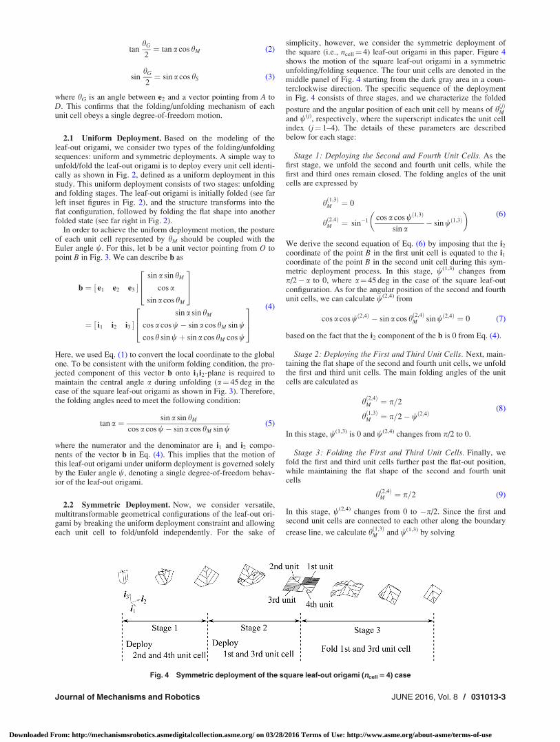
We first examine the geometry of the leaf-out origami.Figure 3(a) shows the flat sheet of the leaf-out origami with creasepatterns. The structure is composed of the Miura-ori unit cellshown as a shaded area in the figure. This unit cell is characterizedby a central angle (a), length of the diagonal line (L), and numberof the layer (N) as shown in Fig. 3(a). We define three differenttypes of crease lines: crease line along diagonal lines (maincreases), crease lines intersecting the main crease lines with anglea (subcreases), and crease lines between adjacent unit cells(boundary creases). The unit cell is repeated throughout the entireleaf-out origami such that the diagonal lines of each unit cell meetat the center point O.
Figure 3(b) shows a configuration during folding/unfolding. Tocharacterize the folding/unfolding motion of the structure, weintroduce a global coordinate (i1; i2; i3) and local coordinate(e1; e2; e3) where ii; ei 2 R3�1 (i¼ 1, 2, and 3) are base vectors ofthe global and local coordinates, respectively. Here, the localcoordinate is defined in each unit cell such that the direction of e2
-axis is aligned with OA as shown in Fig. 3(b). The local e1-axiscoincides with the global i1-axis. We express a rotational (i.e.,folding) motion of the unit cell around the e1-axis by using theEuler angle (w) as follows:
½ e1 e2 e3 � ¼ i1 i2 i3� � 1 0 0
0 cos w �sin w0 sin w cos w
24
35 (1)
In addition to the Euler angle, we define folding angles hM
and hS as angles along the main crease and subcrease lines, respec-tively (see Fig. 3(c), note that hS is a half angle between two adja-cent edge lines.). Since the unit cells follow the Miura-ori pattern,the two folding angles hM and hS are related as follows [15]:
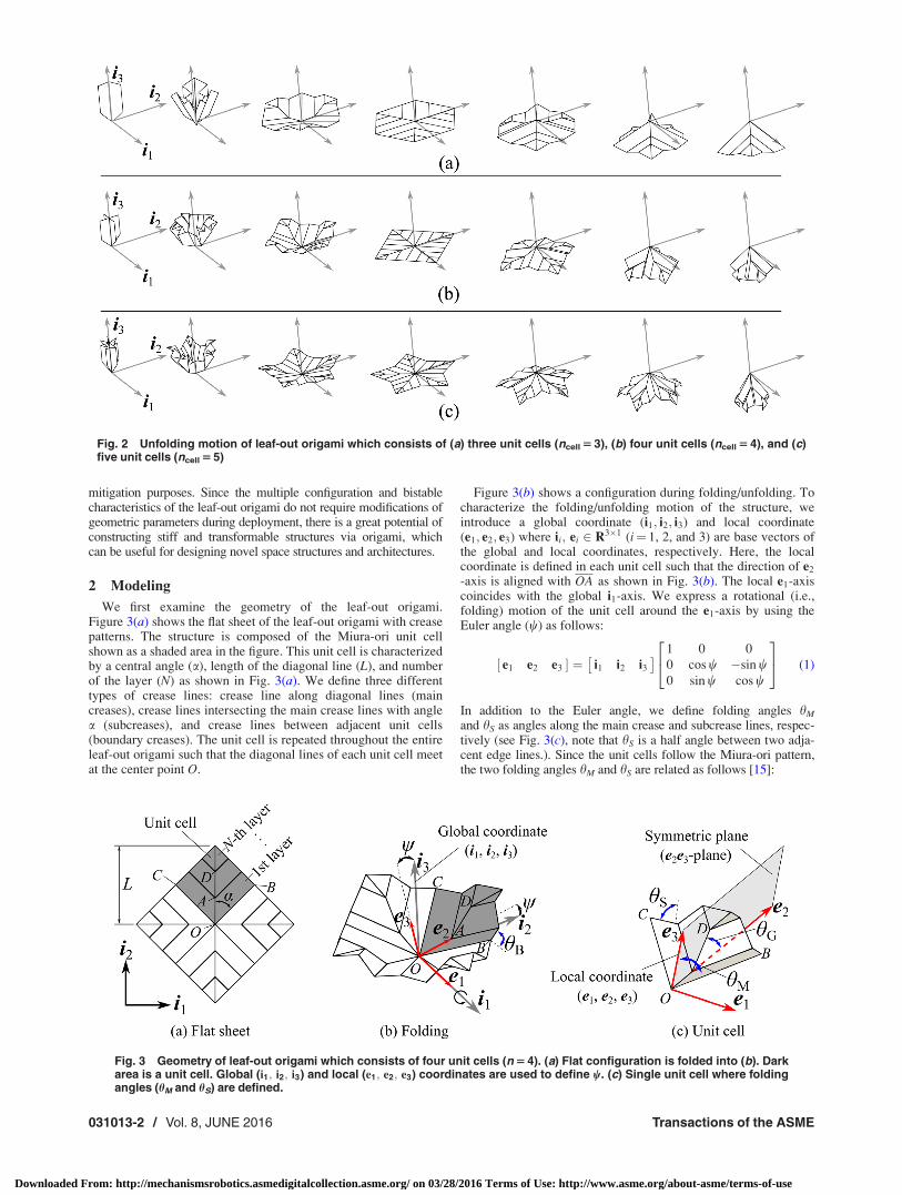
Fig. 2 Unfolding motion of leaf-out origami which consists of (a) three unit cells (ncell 5 3), (b) four unit cells (ncell 5 4), and (c)five unit cells (ncell 5 5)
Fig. 3 Geometry of leaf-out origami which consists of four unit cells (n 5 4). (a) Flat configuration is folded into (b). Darkarea is a unit cell. Global (i1; i2; i3) and local (e1; e2; e3) coordinates are used to define w. (c) Single unit cell where foldingangles (hM and hS) are defined.
031013-2 / Vol. 8, JUNE 2016 Transactions of the ASME
Downloaded From: http://mechanismsrobotics.asmedigitalcollection.asme.org/ on 03/28/2016 Terms of Use: http://www.asme.org/about-asme/terms-of-use
tanhG
2¼ tan a cos hM (2)
sinhG
2¼ sin a cos hS (3)
where hG is an angle between e2 and a vector pointing from A toD. This confirms that the folding/unfolding mechanism of eachunit cell obeys a single degree-of-freedom motion.
2.1 Uniform Deployment. Based on the modeling of theleaf-out origami, we consider two types of the folding/unfoldingsequences: uniform and symmetric deployments. A simple way tounfold/fold the leaf-out origami is to deploy every unit cell identi-cally as shown in Fig. 2, defined as a uniform deployment in thisstudy. This uniform deployment consists of two stages: unfoldingand folding stages. The leaf-out origami is initially folded (see farleft inset figures in Fig. 2), and the structure transforms into theflat configuration, followed by folding the flat shape into anotherfolded state (see far right in Fig. 2).
In order to achieve the uniform deployment motion, the postureof each unit cell represented by hM should be coupled with theEuler angle w. For this, let b be a unit vector pointing from O topoint B in Fig. 3. We can describe b as
b ¼ ½ e1 e2 e3 �sin a sin hM
cos a
sin a cos hM
264
375
¼ ½ i1 i2 i3 �sin a sin hM
cos a cos w� sin a cos hM sin w
cos h sin wþ sin a cos hM cos w
264
375
(4)
Here, we used Eq. (1) to convert the local coordinate to the globalone. To be consistent with the uniform folding condition, the pro-jected component of this vector b onto i1i2-plane is required tomaintain the central angle a during unfolding (a¼ 45 deg in thecase of the square leaf-out origami as shown in Fig. 3). Therefore,the folding angles need to meet the following condition:
tan a ¼ sin a sin hM
cos a cos w� sin a cos hM sin w(5)
where the numerator and the denominator are i1 and i2 compo-nents of the vector b in Eq. (4). This implies that the motion ofthis leaf-out origami under uniform deployment is governed solelyby the Euler angle w, denoting a single degree-of-freedom behav-ior of the leaf-out origami.
2.2 Symmetric Deployment. Now, we consider versatile,multitransformable geometrical configurations of the leaf-out ori-gami by breaking the uniform deployment constraint and allowingeach unit cell to fold/unfold independently. For the sake of
simplicity, however, we consider the symmetric deployment ofthe square (i.e., ncell¼ 4) leaf-out origami in this paper. Figure 4shows the motion of the square leaf-out origami in a symmetricunfolding/folding sequence. The four unit cells are denoted in themiddle panel of Fig. 4 starting from the dark gray area in a coun-terclockwise direction. The specific sequence of the deploymentin Fig. 4 consists of three stages, and we characterize the folded
posture and the angular position of each unit cell by means of hðjÞMand w(j), respectively, where the superscript indicates the unit cellindex (j¼ 1–4). The details of these parameters are describedbelow for each stage:
Stage 1: Deploying the Second and Fourth Unit Cells. As thefirst stage, we unfold the second and fourth unit cells, while thefirst and third ones remain closed. The folding angles of the unitcells are expressed by
h 1;3ð ÞM ¼ 0
h 2;4ð ÞM ¼ sin�1 cos a cos w 1;3ð Þ
sin a� sin w 1;3ð Þ
� �(6)
We derive the second equation of Eq. (6) by imposing that the i2coordinate of the point B in the first unit cell is equated to the i1coordinate of the point B in the second unit cell during this sym-metric deployment process. In this stage, w(1,3) changes fromp/2� a to 0, where a¼ 45 deg in the case of the square leaf-outconfiguration. As for the angular position of the second and fourthunit cells, we can calculate w(2,4) from
cos a cos wð2;4Þ � sin a cos hð2;4ÞM sin wð2;4Þ ¼ 0 (7)
based on the fact that the i2 component of the b is 0 from Eq. (4).
Stage 2: Deploying the First and Third Unit Cells. Next, main-taining the flat shape of the second and fourth unit cells, we unfoldthe first and third unit cells. The main folding angles of the unitcells are calculated as
hð2;4ÞM ¼ p=2
hð1;3ÞM ¼ p=2� wð2;4Þ(8)
In this stage, w(1,3) is 0 and w(2,4) changes from p/2 to 0.
Stage 3: Folding the First and Third Unit Cells. Finally, wefold the first and third unit cells further past the flat-out position,while maintaining the flat shape of the second and fourth unitcells
hð2;4ÞM ¼ p=2 (9)
In this stage, w(2,4) changes from 0 to �p/2. Since the first andsecond unit cells are connected to each other along the boundary
crease line, we calculate hð1;3ÞM and w(1,3) by solving
Fig. 4 Symmetric deployment of the square leaf-out origami (ncell 5 4) case
Journal of Mechanisms and Robotics JUNE 2016, Vol. 8 / 031013-3
Downloaded From: http://mechanismsrobotics.asmedigitalcollection.asme.org/ on 03/28/2016 Terms of Use: http://www.asme.org/about-asme/terms-of-use
bð2;4Þ ¼ cð1;3Þ (10)
where c denotes a vector pointing from O to C (i.e., OC), whichcan be obtained in a way similar to the expression b (Eq. (4))
c ¼ ½ e1 e2 e3 ��sin a sin hM
cos a
sin a cos hM
264
375
¼ ½ i1 i2 i3 ��sin a sin hM
cos a cos w� sin a cos hM sin w
cos h sin wþ sin a cos hM cos w
264
375
(11)
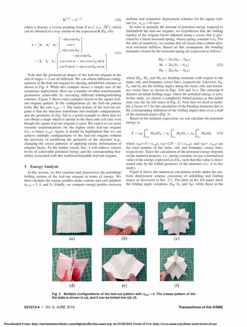
Note that the geometrical shapes of the leaf-out origami at theend of stages 1–3 are all different. We can obtain different config-urations of the leaf-out origami by altering unfold/fold schemes asshown in Fig. 4. While this example shows a simple case of thesymmetric deployment, there are a number of other transformablegeometries achievable by executing different folding/unfoldingschemes. Figure 5 shows such examples based on the square leaf-out origami pattern. In the configuration (f), the leaf-out patternlooks like the case ncell¼ 3. The main feature of the leaf-out ori-gami is that the structure transforms into multiple configurations,and the geometry in Fig. 5(f) is a good example to show that wecan obtain a shape which is similar to the three unit cell case eventhough the square leaf-out origami is used. We expect to see moreversatile transformations for the higher order leaf-out origami(i.e., a larger ncell). Again, it should be highlighted that we canachieve multiple configurations of the leaf-out origami withoutthe necessity of modifying the geometry of the structure (e.g.,changing the crease patterns) or applying elastic deformation oforigami facets. To the further extent, Sec. 3 will address variouslevels of achievable potential energy and the corresponding bist-ability associated with this multitransformable leaf-out origami.
3 Energy Analysis
In this section, we first examine and characterize the unfolding/folding motion of the leaf-out origami in terms of energy. Wethen calculate the energy profiles under various unit cell numbers(ncell¼ 3, 4, and 5). Finally, we compare energy profiles between
uniform and symmetric deployment schemes for the square leaf-out (i.e., ncell¼ 4) case.
In order to quantify the amount of potential energy required tofold/unfold the leaf-out origami, we hypothesize that the foldingrigidity of the origami facets adjoined along a crease line is gov-erned by a linear torsional spring, whose spring constant is kh. Forthe sake of simplicity, we assume that all crease lines exhibit iden-tical torsional stiffness. Based on this assumption, the bendingmoments created by the torsional spring are expressed as follows:
MM ¼ 2khðhM � hM;0ÞMS ¼ 2khðhS � hS;0ÞMB ¼ 2khðhB � hB;0Þ
(12)
where MM, MS, and MB are bending moments with respect to themain, sub, and boundary crease lines, respectively. Likewise, hM,hS, and hB are the folding angles along the main, sub, and bound-ary crease lines as shown in Figs. 3(b) and 3(c). The subscript 0denotes an initial folding stage, where the potential energy is zero.In this study, we choose a completely folded posture as this initialstate (see the far left states in Fig. 2). Note that we need to multi-ply a factor of 2 for the calculation of the bending moments due tothe corresponding definition of the folding angles that cover a halfof the torsional angles (Fig. 3).
Based on the moment expression, we can calculate the potentialenergy as
E ¼ nM
ðhM
hM;0
MMdhM þ nS
ðhS
hS;0
MSdhS þ nB
ðhB
hB;0
MBdhB (13)
where nM(¼N� ncell), nS(¼(2N� 2)� ncell), and nB(¼ ncell) arethe total number of the main, sub, and boundary crease lines,respectively. Since the calculation of the potential energy dependson the material property, i.e., spring constant, we use a normalizedvalue of the energy expressed as E/kh, such that this value is deter-mined only by the folded geometry of the structure (i.e., w in thisstudy).
Figure 6 shows the numerical calculation results under the uni-form deployment scheme consisting of unfolding and foldingstages as discussed in Sec. 2.1. The plots in the left panel showthe folding angle variations (hM, hS, and hB), while those in the
Fig. 5 Multiple configurations of the leaf-out pattern with ncell 5 4. The crease pattern of theflat state is shown in (a), and it can be folded into (b)–(f).
031013-4 / Vol. 8, JUNE 2016 Transactions of the ASME
Downloaded From: http://mechanismsrobotics.asmedigitalcollection.asme.org/ on 03/28/2016 Terms of Use: http://www.asme.org/about-asme/terms-of-use
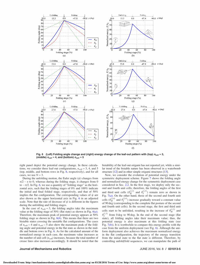
right panel depict the potential energy change. In these calcula-tions, we consider three leaf-out configurations, ncell¼ 3, 4, and 5(top, middle, and bottom rows in Fig. 6, respectively), and for allcases, we use N¼ 3.
During the unfolding motion, the Euler angle (w) changes fromp/2� a to 0, whereas during the folding stage, it changes from 0to �p/2. In Fig. 6, we use a quantity of “folding stage” as the hori-zontal axis, such that the folding stages of 0% and 100% indicatethe initial and final folded stage, respectively, and that of 50%implies the flat configuration. The corresponding values of w arealso shown as the upper horizontal axis in Fig. 6 in an adjustedscale. Note that the rate of decrease of w is different in the figuresduring the unfolding and folding stages.
In the case of ncell¼ 3, the folding angles take the maximumvalue at the folding stage of 50% (flat state) as shown in Fig. 6(a).Therefore, the maximum peak of potential energy appears at 50%folding stage as shown in Fig. 6(b). This means that there are twobistable states crossing the unstable flat configurations. The casesof ncell¼ 4 and ncell¼ 5 also show the maximum peak of the fold-ing angle and potential energy in the flat state as shown in the mid-dle and bottom rows in Fig. 6. As for the calculated amount of thenormalized energy in each case, the maximum value increases asthe number of unit cell (ncell) increases, because the total number ofcrease lines also increases accordingly. It should be noted that the
bistability of the leaf-out origami has not reported yet, while a simi-lar trend of the bistable nature has been observed in a waterbombstructure [12] and in other simple origami structures [13].
Now, we consider the evolution of potential energy under thesymmetric deployment scheme. Figure 7 shows the folding angleand normalized energy change for the symmetric deployment caseconsidered in Sec. 2.2. In the first stage, we deploy only the sec-ond and fourth unit cells; therefore, the folding angles of the first
and third unit cells (hð1;3ÞM and hð1;3ÞS ) remain zero as shown inFig. 7(a). On the other hand, those of the second and fourth unit
cells (hð2;4ÞM and hð2;4ÞS ) increase gradually toward a constant valueof 90 deg (corresponding to the complete flat posture of the secondand fourth unit cells). In the second stage, the first and third unit
cells start to be unfolded, resulting in the increase of hð1;3ÞM and
hð1;3ÞS from 0 deg to 90 deg. In the end of the second stage (flatstate), all folding angles take their maximum value; thus, thepotential energy is also maximum at this folding state (seeFig. 7(b)). It is worthwhile to compare this energy profile with thecase from the uniform deployment (see Fig. 6). Although the uni-form deployment also achieves the maximum normalized energyin the flat configuration, the trajectory of the energy transitionfrom the initial state to the flat state is different. Therefore, bycontrolling unfold/fold sequences, we can manipulate the path of
Fig. 6 (Left) Folding angle change and (right) energy change of the leaf-out pattern with (top) ncell 5 3,(middle) ncell 5 4, and (bottom) ncell 5 5
Journal of Mechanisms and Robotics JUNE 2016, Vol. 8 / 031013-5
Downloaded From: http://mechanismsrobotics.asmedigitalcollection.asme.org/ on 03/28/2016 Terms of Use: http://www.asme.org/about-asme/terms-of-use
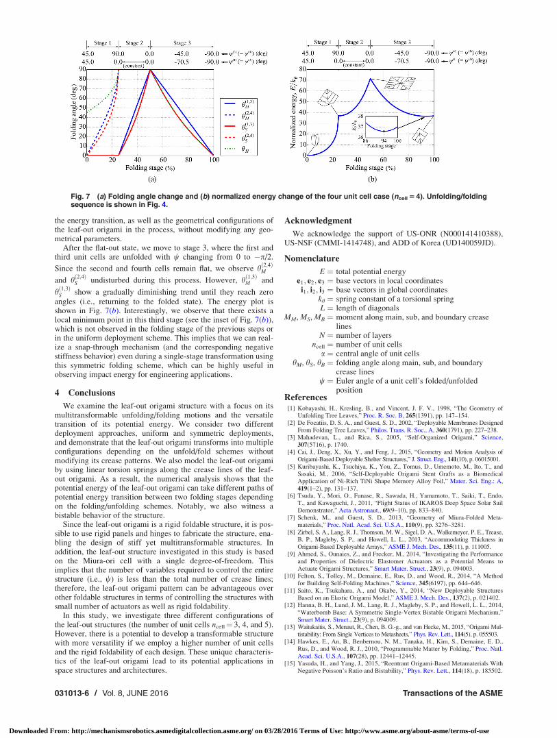
the energy transition, as well as the geometrical configurations ofthe leaf-out origami in the process, without modifying any geo-metrical parameters.
After the flat-out state, we move to stage 3, where the first andthird unit cells are unfolded with w changing from 0 to �p/2.
Since the second and fourth cells remain flat, we observe hð2;4ÞM
and hð2;4ÞS undisturbed during this process. However, hð1;3ÞM and
hð1;3ÞS show a gradually diminishing trend until they reach zeroangles (i.e., returning to the folded state). The energy plot isshown in Fig. 7(b). Interestingly, we observe that there exists alocal minimum point in this third stage (see the inset of Fig. 7(b)),which is not observed in the folding stage of the previous steps orin the uniform deployment scheme. This implies that we can real-ize a snap-through mechanism (and the corresponding negativestiffness behavior) even during a single-stage transformation usingthis symmetric folding scheme, which can be highly useful inobserving impact energy for engineering applications.
4 Conclusions
We examine the leaf-out origami structure with a focus on itsmultitransformable unfolding/folding motions and the versatiletransition of its potential energy. We consider two differentdeployment approaches, uniform and symmetric deployments,and demonstrate that the leaf-out origami transforms into multipleconfigurations depending on the unfold/fold schemes withoutmodifying its crease patterns. We also model the leaf-out origamiby using linear torsion springs along the crease lines of the leaf-out origami. As a result, the numerical analysis shows that thepotential energy of the leaf-out origami can take different paths ofpotential energy transition between two folding stages dependingon the folding/unfolding schemes. Notably, we also witness abistable behavior of the structure.
Since the leaf-out origami is a rigid foldable structure, it is pos-sible to use rigid panels and hinges to fabricate the structure, ena-bling the design of stiff yet multitransformable structures. Inaddition, the leaf-out structure investigated in this study is basedon the Miura-ori cell with a single degree-of-freedom. Thisimplies that the number of variables required to control the entirestructure (i.e., w) is less than the total number of crease lines;therefore, the leaf-out origami pattern can be advantageous overother foldable structures in terms of controlling the structures withsmall number of actuators as well as rigid foldability.
In this study, we investigate three different configurations ofthe leaf-out structures (the number of unit cells ncell¼ 3, 4, and 5).However, there is a potential to develop a transformable structurewith more versatility if we employ a higher number of unit cellsand the rigid foldability of each design. These unique characteris-tics of the leaf-out origami lead to its potential applications inspace structures and architectures.
Acknowledgment
We acknowledge the support of US-ONR (N000141410388),US-NSF (CMMI-1414748), and ADD of Korea (UD140059JD).
Nomenclature
E ¼ total potential energye1; e2; e3 ¼ base vectors in local coordinatesi1; i2; i3 ¼ base vectors in global coordinates
kh ¼ spring constant of a torsional springL ¼ length of diagonals
MM, MS, MB ¼ moment along main, sub, and boundary creaselines
N ¼ number of layersncell ¼ number of unit cells
a ¼ central angle of unit cellshM, hS, hB ¼ folding angle along main, sub, and boundary
crease linesw ¼ Euler angle of a unit cell’s folded/unfolded
positionReferences
[1] Kobayashi, H., Kresling, B., and Vincent, J. F. V., 1998, “The Geometry ofUnfolding Tree Leaves,” Proc. R. Soc. B, 265(1391), pp. 147–154.
[2] De Focatiis, D. S. A., and Guest, S. D., 2002, “Deployable Membranes DesignedFrom Folding Tree Leaves,” Philos. Trans. R. Soc., A, 360(1791), pp. 227–238.
[3] Mahadevan, L., and Rica, S., 2005, “Self-Organized Origami,” Science,307(5716), p. 1740.
[4] Cai, J., Deng, X., Xu, Y., and Feng, J., 2015, “Geometry and Motion Analysis ofOrigami-Based Deployable Shelter Structures,” J. Struct. Eng., 141(10), p. 06015001.
[5] Kuribayashi, K., Tsuchiya, K., You, Z., Tomus, D., Umemoto, M., Ito, T., andSasaki, M., 2006, “Self-Deployable Origami Stent Grafts as a BiomedicalApplication of Ni-Rich TiNi Shape Memory Alloy Foil,” Mater. Sci. Eng.: A,419(1–2), pp. 131–137.
[6] Tsuda, Y., Mori, O., Funase, R., Sawada, H., Yamamoto, T., Saiki, T., Endo,T., and Kawaguchi, J., 2011, “Flight Status of IKAROS Deep Space Solar SailDemonstrator,” Acta Astronaut., 69(9–10), pp. 833–840.
[7] Schenk, M., and Guest, S. D., 2013, “Geometry of Miura-Folded Meta-materials,” Proc. Natl. Acad. Sci. U.S.A., 110(9), pp. 3276–3281.
[8] Zirbel, S. A., Lang, R. J., Thomson, M. W., Sigel, D. A., Walkemeyer, P. E., Trease,B. P., Magleby, S. P., and Howell, L. L., 2013, “Accommodating Thickness inOrigami-Based Deployable Arrays,” ASME J. Mech. Des., 135(11), p. 111005.
[9] Ahmed, S., Ounaies, Z., and Frecker, M., 2014, “Investigating the Performanceand Properties of Dielectric Elastomer Actuators as a Potential Means toActuate Origami Structures,” Smart Mater. Struct., 23(9), p. 094003.
[10] Felton, S., Tolley, M., Demaine, E., Rus, D., and Wood, R., 2014, “A Methodfor Building Self-Folding Machines,” Science, 345(6197), pp. 644–646.
[11] Saito, K., Tsukahara, A., and Okabe, Y., 2014, “New Deployable StructuresBased on an Elastic Origami Model,” ASME J. Mech. Des., 137(2), p. 021402.
[12] Hanna, B. H., Lund, J. M., Lang, R. J., Magleby, S. P., and Howell, L. L., 2014,“Waterbomb Base: A Symmetric Single-Vertex Bistable Origami Mechanism,”Smart Mater. Struct., 23(9), p. 094009.
[13] Waitukaitis, S., Menaut, R., Chen, B. G.-g., and van Hecke, M., 2015, “Origami Mul-tistability: From Single Vertices to Metasheets,” Phys. Rev. Lett., 114(5), p. 055503.
[14] Hawkes, E., An, B., Benbernou, N. M., Tanaka, H., Kim, S., Demaine, E. D.,Rus, D., and Wood, R. J., 2010, “Programmable Matter by Folding,” Proc. Natl.Acad. Sci. U.S.A., 107(28), pp. 12441–12445.
[15] Yasuda, H., and Yang, J., 2015, “Reentrant Origami-Based Metamaterials WithNegative Poisson’s Ratio and Bistability,” Phys. Rev. Lett., 114(18), p. 185502.
Fig. 7 (a) Folding angle change and (b) normalized energy change of the four unit cell case (ncell 5 4). Unfolding/foldingsequence is shown in Fig. 4.
031013-6 / Vol. 8, JUNE 2016 Transactions of the ASME
Downloaded From: http://mechanismsrobotics.asmedigitalcollection.asme.org/ on 03/28/2016 Terms of Use: http://www.asme.org/about-asme/terms-of-use


![DB [04.2013] Hiromi](https://static.fdocuments.us/doc/165x107/552c29084a7959f07c8b466f/db-042013-hiromi.jpg)