HIRA 2 VPOS - alberici.it
40
1 Hira 2 VPOS Mini, Midi, Maxi standard display Operator’s Manual Rev. 2.01 EN HIRA 2 VPOS Operator’s Manual Progettazione e produzione di sistemi di pagamento e accessori per macchine Gaming, Vending e Car-Wash Design and manufacture of payment systems and accessories for the Industries of Gaming, Vending and CarWash
Transcript of HIRA 2 VPOS - alberici.it

1
Hira 2 VPOS Mini, Midi, Maxi standard display
Operator’s Manual
Rev. 2.01 EN
HIRA 2 VPOS
Operator’s Manual
Progettazione e produzione di sistemi di pagamento e accessori per macchine Gaming, Vending e Car-Wash Design
and manufacture of payment systems and accessories for the Industries of Gaming, Vending and CarWash

2
This manual has been drafted with the utmost care. Nevertheless, it is not possible to guarantee at all
times the absolute correspondence of the descriptions contained therein with the actual
characteristics of the product.
Alberici S.p.A. declines any and all responsibility towards the User with reference to damages,
losses, or claims of third parties, resulting from the use of the product or caused by incorrect
interpretations of this manual.
Alberici S.p.A. reserves the right to modify, without prior notice and in any way, any part of this
manual and the technical specifications of this product, as part of the continuous pursuit of
improvement of its products.
NOTICE

3
CONTENTS
1. Package content: .......................................................................................................................... 4
2. Components description ............................................................................................................... 4
3. Product description ...................................................................................................................... 5
4. Warning ........................................................................................................................................ 5
5. Installation .................................................................................................................................... 6
6. Operation ...................................................................................................................................... 9
7. System configuration…………………………………………………………………………..11
8. Messages……………………………………………………………………………………….22
9. Cleaning of the Note Validator .................................................................................................. 24
11. Disposal of the product ............................................................................................................... 25
12. Terms of Guarantee .................................................................................................................... 25
13. Customer Service ........................................................................................................................ 25
STORICO REVISIONI
Revisione n° Data Modifica Note
Creazione 1.00 30.12.14 Creazione FW v. 1.14 (scheda CMS Full)
Rev. 1.01 18.02.15 Funzioni abilitazione/disabilitazione e erogazione via GSM. FW v. 1.16
Rev. 1.02 10.03.15 Aumentato timeout visualizzazione valore svuotato. Inserito 1’ Timeout di uscita in menu svuotamento
FW v. 1.18
Rev. 1.03 27.06.15 Abbassato timeout cancellazione automatica credito residuo FW v. 1.19
Rev. 1.04 29.04.16 Inserito lettore ACS FW v. 1.23
Rev. 2.00 07.03.19 Uniformato manuale con edizione italiana FW v. 1.26
Rev. 2.01 04.06.20 Integrazione VPOS Touch Nayax FW v. 1.38.04NL - ARM v. 1.03

4
Dear Customer,
we would like to thank you and congratulate for your choice. We trust that you will appreciate the
quality and performance of the HIRA TWO automatic Change Machine.
This machine operates by cctalk protocol, the well-established serial communication mode that
provides security and precision.
1. Package content
The package contains:
1. the Alberici HIRA 2 / Hira 2 Maxi Change machine
2. 1 pair of keys
3. the power cable (see inside of money box)
4. the instruction manual (this manual)
This product has been packed with the utmost care. In the case that you receive it damaged or
incomplete, please notify immediately your findings to the Carrier.
2. Components description
E
A
I
P L
G
M
F
POS. COD. DESCRIZIONE
A A-CM0249 Power Switching box RD-125
B SH-5L21 CMS ARM Full ChangeOne p.c. board
C AA-0177 Hub pcb for Peripheral units
D K-02C-020070 2 x HopperOne S11 ccTalk STD
E AA-0309
AA-0315 AA-0333
SECTOR 100 capacity extension (HIRA 2 Mini)
SECTOR 300 capacity extension (HIRA 2 Midi)
SECTOR 100 capacity extension (HIRA 2 Maxi)
F
LB-LU01-0004
or else: LB-MU02-0004
BillyOne ccTalk note validator
or else: OryOne ccTalk (stackered) note validator
G PL-MK21-ET6H Halo quick-fix square 21 RGB pushbutton
H AM-1509 Flat key lock L=21mm keyed different
I AM-1305, else HR1-011A-P00
Plastic “A” coinbox, or else Metal coin box
L GE-66SU AL66S coin acceptor
M IM-N000-0L10 PP coin entry slot
(N) C-140102 VPOS Touch Nayax 3G EU-Marshall
(O’) A-CM0059 Interface pcb for VPOS Touch Nayax
(O”) A-CM0068 Interface pcb for WL Valina POS
(P) CH-BC01-0001 ACS RFID Card/Key reader
Please read carefully this handbook, to obtain the most from your machine.
O’/ O”
N
C
D
A
5
3. Product description
3.1 General data
Technical specs: HIRA 2
Size:
Weight:
Voltage:
Nominal power:
Operation temperature:
Installation:
Coin capacity:
Components:
Power supply unit
Control board
Note validator
Pay-out Hopper
Coin acceptor
POS Terminal (option)
RFID reader (option)
Remote audit (option)
See page 6
Mini: 30 Kg (50 with floor-stand) - Midi: 39 Kg (59 Kg with floor-stand) – Maxi:35
Kg (55 with floor-stand)
230 Vac - 50 Hz
340 W max
0°C ÷ +50°C
Desktop or on floor-stand or wall-mount, indoor Mini: 4000 - Midi: 5600 - Maxi: 7200
Power switching 340W
CMS ARM Full ChangeOne p.c. board,with DISPLAY LCD 2x16
BILLYONE, or else: ORYONE (with stacker)
2 x HopperOne S11 or AH4 (also together)
AL66S cctalk
VPOS Touch Nayax, or preset for Worldline Valina
ACS RFID Card/Key reader
Alberici Hermes GPS/GSM/GPRS (*)
Notice: Euro is the preset currency. If you require a different currency, please request your
currency before placing your order. (*) The system requires that the B-to-B Alberici SIM card is inserted into the Hermes module SIM slot, and
that a subscription is entered into the ARGO Portal, in order to control the machine via the Internet.
3.2 Available functions - Change of notes and coins into 1 or 2 denomination coins/tokens, at User’s choice
- Change of notes and coins into 1 denomination tokens, with cash change returned
- Purchase of tokens by POS transaction
- Control of accounts via display (by on-board keys)
- Programmable via menu (by on-board keys)
- Change of display language by external “LANGUAGE/SEL+” pushbutton, at User’s choice.
4. Warning
- Comply with the instructions in this manual
- Switch power off before any maintenance operation
- Use only within the recommended temperature/humidity range
- Do not expose the machine (and especially the mote acceptor front plate) to direct
sun light or to incandescent light (> 3000 Lux)
- When in presence of car exhaust gas or smoke, clean and check the components (the note acceptor
in particular) regularly and frequently.
- Do not favour contact with dusts or chemical moisture or sprays, water or other liquids
- Install indoor
- Wipe clean by a dry piece of cloth (or slightly wet with alcohol)
- Do not use thinners or organic solvents
- The note acceptor could reject (or get jammed by) stained notes, or worn out, wet, wrinkled, torn,
dog-eared, oil-smeared, with sticking tape or similarly affected.
- Clean monthly the sensors of the note acceptor. Remove paper dust that has accumulated on the
drive wheels, by a clean piece of cloth or a cotton swab. Do not use alcohol nor solvents or scrapers.
!

6
5. Installation PAY ATTENTION: IT IS ESSENTIAL TO FASTEN THE MACHINE TO A
SOLID WALL BY USING RELIABLE EXPANSION BOLTS.
IT IS RECOMMENDED THAT YOU MAKE USE OF THE WALL-MOUNT
SLAB (ref. HRP-021A-V06 for HIRA 2 Mini, HRM-AM15-V06 for HIRA 2
Midi, HRS-015A-V06 for HIRA 2 Maxi) .
All measures in mm
Put the Change Machine in place and fasten it
to the wall by expansion bolts through the “x”
holes in the rear side of the cabinet. Keep the
on-off switch accessible. In addition, the
machine can be secured to the floor: the large
holes at the foot allow securing the machine
by a binding chain.
The fastening slab allows to easily securing
the machine to the wall. Once fixed the slab
to the wall, the machine can be either fastened
to it by screws (“Z” holes), or just hung upon
the slab’s hooks, so as to remove it at ease.
!
Mini
Maxi Midi
7
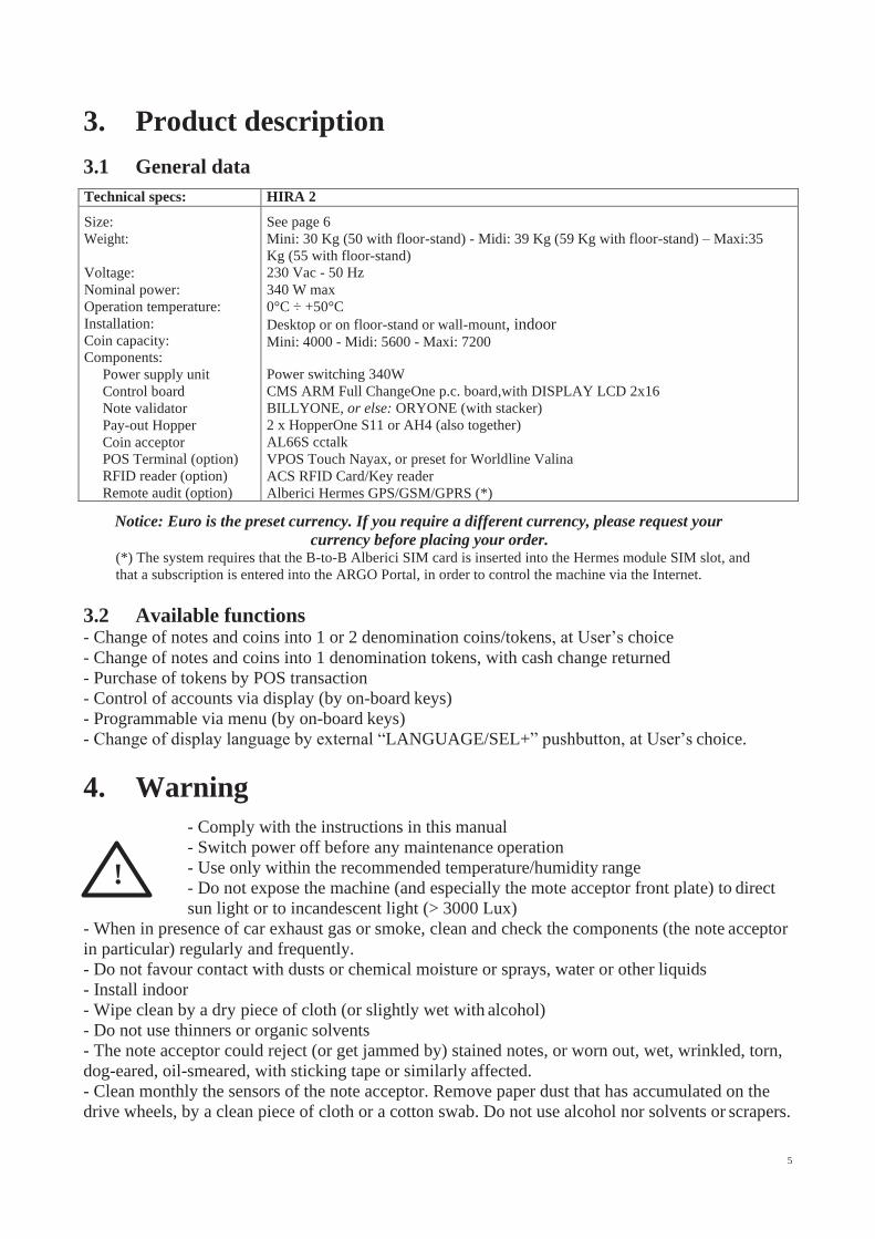
WALL-MOUNT SLABS:
HRS-015A-V06 for HIRA 2 Maxi
430
Prepare the tunnel for the
power cable in the wall
(corresponding to “Y”
Hole in the slab).
Fasten the slab to the
wall by sturdy expansion
bolts, through the 6
“X” ( 12 mm) holes.
Connect the cable to its socket behind the
machine, and hang the latter on the 4 “W”
supporting hooks.
Fix the machine to the slab by M8 screws
through the three “Z” threaded holes, if you
do not plan to often remove and re−hang
the machine up to its ”y” hooks.
HRM-AM15-V06 FOR HIRA 2 MIDI
430
Prepare the tunnel for the
power cable in the wall
(corresponding to “Y”
Hole in the slab).
Fasten the slab to the
wall by sturdy expansion
bolts, through the 6
“X” ( 12 mm) holes.
Connect the cable to its
socket behind the machine,
and hang the latter on the 4
“W” supporting hooks.
Fix the machine to the slab by M8 screws
through the two “Z” threaded holes, if you
do not plan to often remove and re−hang
the machine up to its ”y” hooks.
12
12
13
5
13
5
45
43
0
43
0
45
45
45
40
40
45
45
70
70
70
22
0
25
0
22
0
25
0
70
62
5
76
0

HRP-021A-V06 FOR HIRA 2 MINI
430
Prepare the tunnel for the
power cable in the wall
(corresponding to “Y”
Hole in the slab).
Fasten the slab to the
wall by sturdy expansion
bolts, through the 6
“X” ( 12 mm) holes.
Connect the cable to its socket behind the
machine, and hang the latter on the 4 “W”
supporting hooks.
Fix the machine to the slab by M8 screws
through the two “Z” threaded holes, if you
do not plan to often remove and re−hang
the machine up to its ”y” hooks.
PREPARATION FOR USE:
PAY ATTENTION: FILL THE HOPPERS ONLY WHEN THE MACHINE IS OFF
Open the door and locate extensions capacity on top of the hopper.
Unlock the latch A (white slide) of the cover and slide
the latter fully out towards the outside, until is positioned
as a pilot chute: pour into the hopper the coins or tokens to
be dispensed as change.
Unlock again the latch A and slide the cover back
to “closed” position.
Close the door of the machine.
Plug the power cable in, and turn the main switch on.
Component check and self-setting shall start automatically. At the end, a message will inform that
the machine is ready for operation, showing what coin(s) (tokens) value(s) will be paid in exchange
for notes and coins introduced, as well as a welcome wording.
This message takes shifts with:
As soon as the control board enables the note acceptor, the latter’s front slot flashes once in blue
colour for each enabled note, or once in red for each disabled note. For instance, if the 5, 10, 20
Euro notes are enabled, and the 50 and 100 Euro notes are disabled, the front slot will flash 3 times
in blue colour and 2 (twice) in red.
The machine is now ready to operate.
12
140
CHANGES TO
2,00 € - 1,00 €
CHANGEONE
Promo message
12
0
50
45
40
60
45 70
18
0
47
0

6. Operation
Three buttons are available: “1” and “2” (“SEL-“ and “SEL+”) allow the User to choose the coin
(or token) value he wants back as change; third button allows the user to choose the language he
wants on the display (English, French, German, Italian and Dutch are available. Ask before placing
order for other languages options). The machine offers two different modes of operation, depending
on whether the operation mode is set to AUTOMATIC MODE or to MANUAL MODE.
6.1 MANUAL MODE
6.1.1 CASH: when inserted money reaches the lowest value of token or coin, the button(s) will lit up
green . Press the button corresponding to the change (token) desired. If the machine is set to
Tokens+Change, it will be possible to choose the desired number of tokens.
If the machine is set to Tokens or to Tokens+Change, and the Bonus has been set, introduce money
until the searched amount is reached, then press the OK button.
6.1.2 POS: POS operation is available if the machine menu has been set up to deliver Tokens only.
If the machine is set for dispensing Coins, POS operation will be automatically disabled. POS will
be available only if the machine is equipped with single-coin Hoppers; the configuration menu in
machines equipped with multi-coin Hopper Discrimjnator shall make the POS option unavailable.
The display prompts to touch the “SEL“ button if purchase by credit/debit card is desired:
Press the “SEL“ button, the display will show:
- Lean your RFID ChipCard against the POS Terminal: you will be invited to select how many
tokens must be purchased: touch the “SEL” buttons as many times as necessary to obtain the
desired quantity. Then confirm by the OK button.
SEL+ … SEL - > OK
- You will now be prompted to choose the value of the tokens that
must be purchased (that is, which denomination; that is, from which
hopper): make your choice, ex. 1€ Token:
- then press the “OK” button, so that the machine
will dispense the selected number of tokens:
and the bank network will deduct the equivalent amount from your account.
Please notice: if, within 30 seconds after having pressed the SEL- button, the User has
not continued the payment steps, the system returns to stand-by.
6.2 AUTOMATIC MODE
6.2.1 CASH: when a note or coin is inserted, the credited amount is displayed, and the control board
starts the pay-out by the hopper(s). The machine combines the coins contained in the hoppers. If the
machine is set to Tokens+Change, all the tokens that can be bought by the inserted sum will be
dispensed, with the back change in addition. At the end of the payout cycle, the display will show
both the inserted amount as well as the amount paid out.
6.2.1.A PAY-OUT TABLE ENABLED AND PROGRAMMED: when a note or coin is inserted, the
display shows the credited amount, and the machine shall automatically pay-out according to the
combination that the Operator has pre-programmed for the amount inserted (see section 7.3.5 B
DISPENSING MODE SETUP). By enabling such pay-out table from the menu settings, the User will only
be able to get the tokens and/or coins that can be bought by the inserted money, according to the combination
preset by the Operator. See the setting flow-chart in section 7.3.5 B.
Press SEL to
start CARD mode
INSTRUCTIONS ON
THE POS SCREEN
Select
Token 1
Credit 3,00€
Tokens paid 3
Choose Value
Token > 1,00€
Select
Token 3

6.2.2 POS: POS payments shall only allow to obtain tokens. If the machine is set for dispensing
coins, POS operation will be automatically disabled. POS will be available only if the machine is
equipped with single-coin Hopper; in machines equipped with multi-coin Hopper Discriminator
the configuration menu shall make the POS option unavailable. Operation takes place as described
in section 6.1.2 POS above, with the provision that the User will be able to choose only among the
payment levels preset by the Operator.
Please notice: if, within 30 seconds after having pressed the SEL- button, the User has
not continued the payment steps, the system returns to stand-by.
WARNING: If there are not enough coins/tokens in the hopper to fulfil the whole payout request, the remaining credit
shall be displayed and retained in memory. Switch off the machine, fill the hoppers, and switch on again: the
remaining credit shall be paid out.
An alternative option is to set the Remaining Credit Menu (see section 7.3.14) so as to cancel the remaining credit -
and at the same time record it in the Accounts menu - by switching the machine off and on again.
6.3 RECHARGE OF CARD / KEY
When equipped with the ACS Card/Key reader (see 7.3.5D), the Money Changer can operate as
recharger of credit for User Card/Keys. These can then be used to purchase services or goods
from nearby self-service dispensers or distributor kiosks, provided that the ACS readers in such
kiosks have been initialized with the same PIN as the one in the Change Machine. When the User
Card/Key is in the Hira ACS reader, and money is introduced, the display will prompt for
pressing any green-lit button to load the credit onto the Card/Key.
6.4 OPERATIONS WITH RFID CARD/KEYS
If the machine is equipped with the ACS Reader for the RFID Card/Keys, it is possible to use such
Card/Keys to obtain or perform useful functions, according to which type of Card/Key is inserted.
6.4.1 Operation with User Card/Key
When inserting a compatible RFID User Card/Key (must be
initialized with the same password as the RFID reader - see
section 7.3.5D SET UP CASHLESS), the available credit gets
shown, and a pushbutton will lit up and flash green.
If more credit must be loaded, insert coins and/or notes
until the desired value is attained, then wait until the
storing message (“Data are being stored”) disappears,
then remove the Card/Key now loaded with new credit.
The Card/Key can now be used to buy services/products
from machines equipped with ACS reader provided that such
ACS readers too have been initialized with the same password as the RFID reader of the machine.
6.4.2 Operation with Service or Master Card/Key (see also section 7.3.5D)
Insert the Service Card/Key (white) or the Master Card/Key (black) in the ACS reader to get access
to the Service Menu (no need to open the machine). The Service menu allows to: 1) initialize the
User Card/Keys, as well as to 2) check the Accounts Data. By the Service Card/Key, operators can
reset the Partial Accounts. By the Master Card/Key, the operator can reset all Accounts data and can
also - if the machine is connected to the printer - print out the Account records (see steps at foot next page).
Please note that the RFID Keys must be first initialized to get enabled for use (see section 7.3.5D).
Press green button
to load credit
Available Credit:
NN,nn

PRINT ACCOUNTS: when the machine is connected to the printer, it is possible to get a strip reporting records of the
accounts. Proceed as follows:
1. Insert Master (Black) Card/Key.
2. Display shows “Account Records”: hold the greenlit (Language) pushbutton pressed until display shows “Partials
in” (depending on board version, it can show other descriptions).
3. Navigate the Accounts menu until finding “Print Accounts” (depending on board version), or else go straight to 4.
4. Press OK Pushbutton: its light will flash yellow as long as the printing goes on.
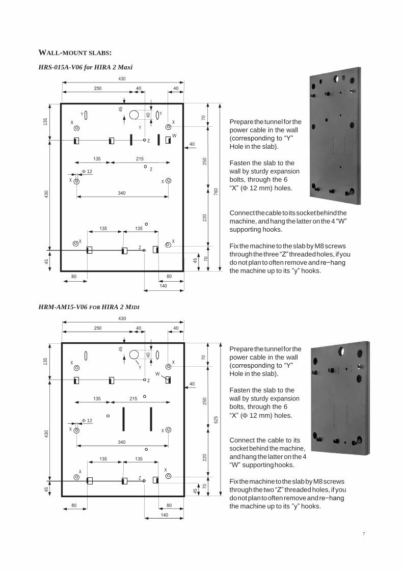
7. System configuration 7.1 Default configuration
The HIRA 2 Maxi is preset by default as follows (unless requested for different setup):
Control Board Parameters Pay-out mode = AUTOMATIC
Bonus = DISABLED
Level sensors = DISABLED
Hopper S11 Parameters Hoppers no. 1 / 2 (*) = € 2.00 = ENABLED
BILLY/ORY ONE Validator [ccTalk] Parameters € 5.00 - …. - € 100.00 = ENABLED AL66 S
[ccTalk]coin acceptor Parameters € 0.05 - € 0.10 - € 0.20 = DISABLED
€ 0.50 - € 1.00 - € 2.00 = ENABLED (*) The Hopper 1 (primary) is placed at the left side (watching the
machine from the front); Hopper 2 (secondary) is placed at the right side.
Set Dip-switches in HP1 to address 3 (all DS to OFF)
Set Dip-switches in HP2 to 4 (no. 1=ON, nos. 2= 3=OFF).
Restore default configuration
If any variation is made, it will be possible to restore the default configuration as follows:
enter the initial menu, scroll by UP and DOWN keys and choose RESTORE DEFAULT CONFIGURATION
then press OK; the message DEFAULT CONFIG. RESTORED will be displayed.
NOTICE: the RESTORE DEFAULT CONFIGURATION command resets the default PIN code (0000) .
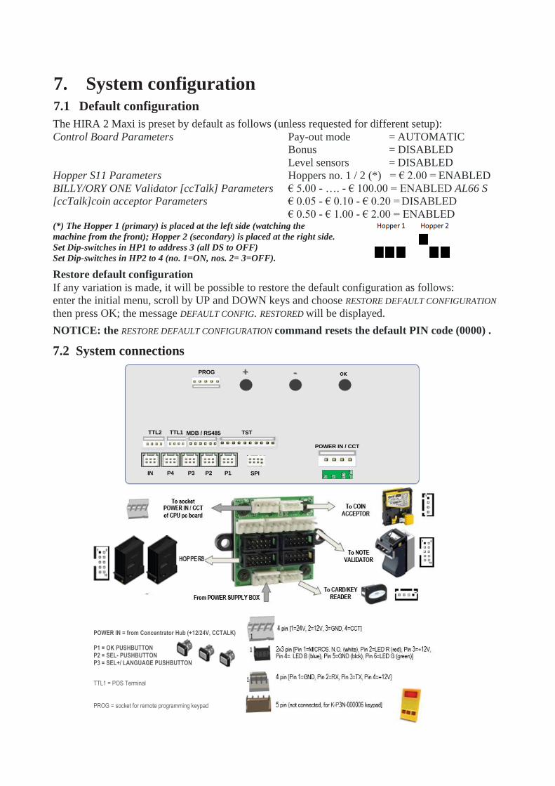
7.2 System connections
IN P4 P3 P2 P1
POWER IN / CCT
TST
MDB / RS485
TTL1
TTL2
PROG
SPI
POWER IN = from Concentrator Hub (+12/24V, CCTALK) P1 = OK PUSHBUTTON P2 = SEL- PUSHBUTTON P3 = SEL+/ LANGUAGE PUSHBUTTON
TTL1 = POS Terminal PROG = socket for remote programming keypad
BONUS
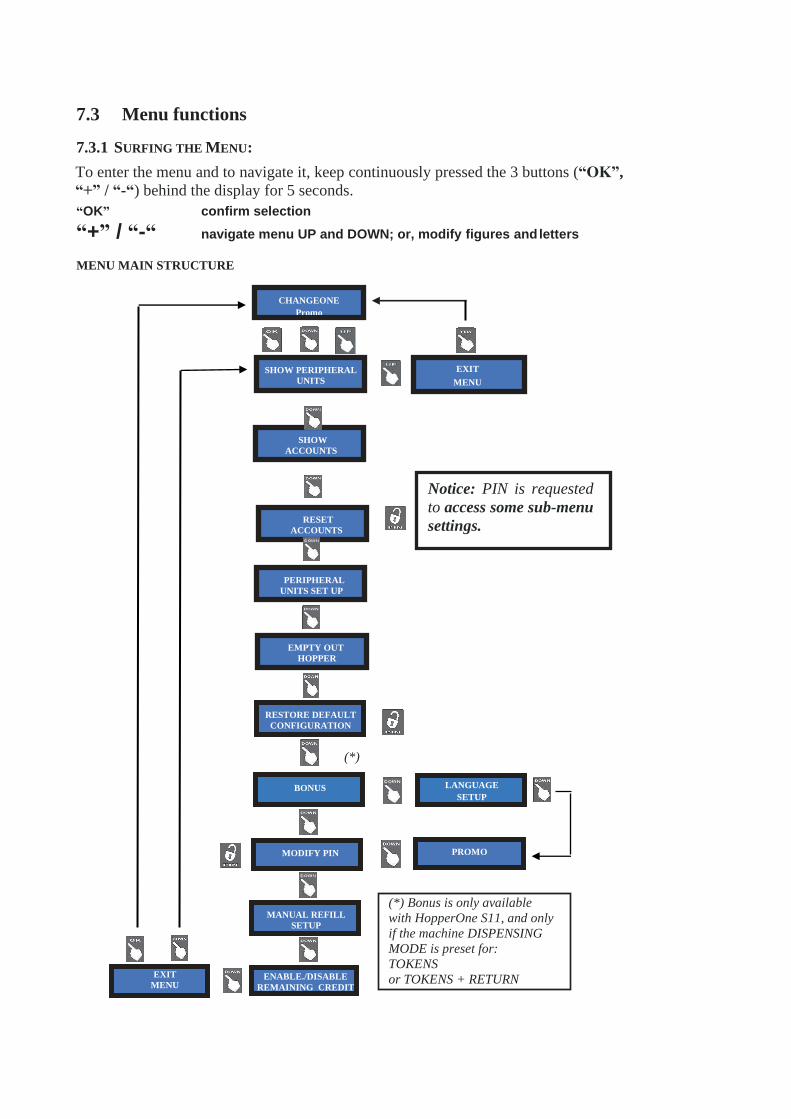
7.3 Menu functions
7.3.1 SURFING THE MENU:
To enter the menu and to navigate it, keep continuously pressed the 3 buttons (“OK”,
“+” / “-“) behind the display for 5 seconds.
“OK” confirm selection
“+” / “-“ navigate menu UP and DOWN; or, modify figures and letters
MENU MAIN STRUCTURE
CHANGEONE
Promo
SHOW PERIPHERAL
UNITS
EXIT
MENU
PERIPHERAL
UNITS SET UP
EXIT
MENU ENABLE./DISABLE
REMAINING CREDIT
RESTORE DEFAULT
CONFIGURATION
RESET
ACCOUNTS
Notice: PIN is requested
to access some sub-menu
settings.
SHOW
ACCOUNTS
MANUAL REFILL
SETUP
EMPTY OUT
HOPPER
(*) Bonus is only available
with HopperOne S11, and only
if the machine DISPENSING
MODE is preset for:
TOKENS
or TOKENS + RETURN
CHANGE
MODIFY PIN PROMO
LANGUAGE
SETUP
(*)
All Totals
cancelled
Enter PIN
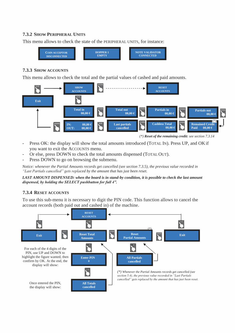
7.3.2 SHOW PERIPHERAL UNITS
This menu allows to check the state of the PERIPHERAL UNITS, for instance:
7.3.3 SHOW ACCOUNTS
This menu allows to check the total and the partial values of cashed and paid amounts.
(*) Reset of the remaining credit: see section 7.3.14
- Press OK: the display will show the total amounts introduced (TOTAL IN). Press UP, and OK if
you want to exit the ACCOUNTS menu.
- Or else, press DOWN to check the total amounts dispensed (TOTAL OUT).
- Press DOWN to go on browsing the submenu.
Notice: whenever the Partial Amounts records get cancelled (see section 7.3.5), the previous value recorded in
“Last Partials cancelled” gets replaced by the amount that has just been reset.
LAST AMOUNT DISPENSED: when the board is in stand-by condition, it is possible to check the last amount
dispensed, by holding the SELECT pushbutton for full 4”.
7.3.4 RESET ACCOUNTS
To use this sub-menu it is necessary to digit the PIN code. This function allows to cancel the
account records (both paid out and cashed in) of the machine.
For each of the 4 digits of the
PIN, use UP and DOWN to
highlight the figure wanted, then
confirm by OK. At the end, the
display will show:
Once entered the PIN,
the display will show:
(*) Whenever the Partial Amounts records get cancelled (see
section 5.4), the previous value recorded in “Last Partials
cancelled” gets replaced by the amount that has just been reset.
Exit
(*)
Reset
Partial Amounts
COIN ACCEPTOR
DISCONNECTED
HOPPER 1
EMPTY
NOTE VALIDATOR
CONNECTED
SHOW
ACCOUNTS
RESET
ACCOUNTS
RESET
ACCOUNTS
(*) Remained Credit
Paid 00,00 € 00,00 €
00,00 €
IN:
OUT:
All Partials
cancelled
Exit Reset Total
Amounts Exit
Cashless Total
00,00 € Last partials
cancelled
Partials out
00,00 €
Partials in
00,00 €
Total out
00,00 €
Total in
00,00 €

Set up Hopper 1 :
2,00 €
7.3.5 SETTING THE PERIPHERAL UNITS
This menu allows to set up the denominations accepted by the note validator and by the coin
acceptor, as well as the value of the coins/tokens dispensed. It also permits to set the change mode
as either automatic or manual, and to enable/disable the full/void sensors of the hoppers.
(*)
Single-coin hopper, and menu set for COINS Single-coin hopper, and menu set for TOKENS
POS Enable/disable option available, POS
not working even if set to ‘enabled’
POS Enable/disable option available,
Pay-out Table Not available in the Menu Pay-out Table Available in the Menu only in Automatic Mode
Multi-coin hopper, menu set for COINS
POS Enable/disable option not available, POS not working
Pay-out Table Not available in the Menu
PERIPHERAL UNITS
SETUP
EMPTY OUT
HOPPERS
Set up
Cashless
Set up
Dispense mode
Set up
TOKEN + CHANGE
Set up
TOKENS
Set up
COINS
0,50
OK OK OK
< 2,00 > 1,00 OK NO
1,00 < 0,50 > 2,00
OK
2,00 < 1,00> 0,50
NO OK OK
< 2,00 > 1,00 0,50
NO OK OK
Set up
Coin acceptor
Set up
GSM / GPRS
2,00 < 1,00 > 0,50
OK OK OK
< 5 > 10 20 50 100
NO OK OK OK OK
5 < 10 > 20 50 100
NO OK OK OK OK
< 5 > 10 20 50 100
OK OK OK OK OK
Set up
Note validator Exit
5 10 < 20 > 50 100
OK OK OK OK OK
5 < 10 > 20 50 100
OK OK OK OK OK
Set up Hopper 2 :
1,00 €
Dispensing mode
MANUAL
(*) Press OK, then
Down or Up to modify amounts by steps of
0,05€ each, then again
OK to confirm and
move to Hopper 2
Level sensors
enabled
Enable / Disable
POS
Data / Ora
-
>>>>>> Enabling POS
will make COINS option
unavailable!
(***)
Payout Settings
Enabled / Disabled
(**) Press Down/Up to select Pay-out Table or to
discard it, then press OK to confirm. For Pay-out
settings, go to section 7.3.5.B
(***) Press Down/Up to choose POS type (Nayax,
Payter, Valina), then press OK to confirm.
(**)
(*)
Dispensing mode
AUTOMATIC
Enable ?
Yes
Select POS
Nayax / Valina / Payter
Level sensors
disabled

Set up Hopper 1 :
2,00 €
7.3.5.A NOTE VALIDATOR SETUP
All the programmed note values get automatically enabled at the initial check. To modify this
default condition, press OK to get to the first option (ex. 5 €) and highlight it, then press UP or
DOWN to reverse its state. Press OK to shift to the next option (ex. 10 €).
7.3.5.A COIN SELECTOR SETUP
The board automatically detects the presence of the coin selector during initial check. Among the
accepted coins (0.05-to-2 €), the following ones get enabled by default: 0.50 € - 1.00 € - 2.00 €.
To modify this condition, press OK to get to the first option (ex. 2 €) and highlight it, then press UP
or DOWN to reverse its state. Press OK to shift to the next option (ex. 1 €).
7.3.5.B DISPENSING MODE SETUP
Allows to choose whether to dispense COINS or TOKENS or TOKENS+CHANGE, and whether the
DISPENSING MODE will be AUTOMATIC or MANUAL. The values in the hoppers are set by this sub-menu.
It also permits to monitor the level of the coins in the hopper(s) by the electronic sensors.
(*)
Set up
Coin acceptor
2,00 1,00 < 0,50 >
OK NO OK OK OK
< 1,00 > 0,50 2,00
OK
0,50
OK
< 2,00 > 1,00
OK OK 0,50
OK
< 2,00 > 1,00
NO OK
5 < 10 > 20 50 100
OK OK OK OK OK
5 10 < 20 > 50 100
OK OK OK OK OK
Set up
Note validator
5 10 20 50 < 100>
OK OK OK OK OK
<5 > 10 20 50 100
OK OK OK OK OK <5 > 10 20 50 100
NO OK OK OK OK
Set up
Dispense mode
Set up
TOKEN + CHANGE
Set up
TOKENS
Set up
COINS
Set up Hopper 2 :
1,00 €
Dispensing mode
MANUAL 1P
(*) Press OK, then
Down or Up to modify amounts by steps of
0,05€ each, then again
OK to confirm and
move to Hopper 2.
Max. value for tokens
= 12,70 €.
Level sensors
enabled
Enable / Disable
POS
>>>>>> Enabling POS
will make COINS option
unavailable!
(**) Press Down/Up to
choose POS type (Nayax,
Payter, Valina), then
press OK to confirm.
(**) Payout Settings
Enabled / Disabled (***) Press Down/Up to
select Pay-out Table or to
discard it, then press OK
to confirm.
(***)
(*)
Dispensing mode
AUTOMATIC
Enable ?
Yes
Select POS
Nayax / Valina / Payter
Level sensors
disabled <LEV1 HP1 HP2>
0,00€ 0 0
(*****) Setting of the
Pay-out Table: see next page
(*****)
Dispensing mode
MANUAL 2P
(****)MANUAL 1P: choose the
paying hopper by SEL, and
confirm by OK.
2P MANUAL: press the button
of the paying hopper desired
(****)
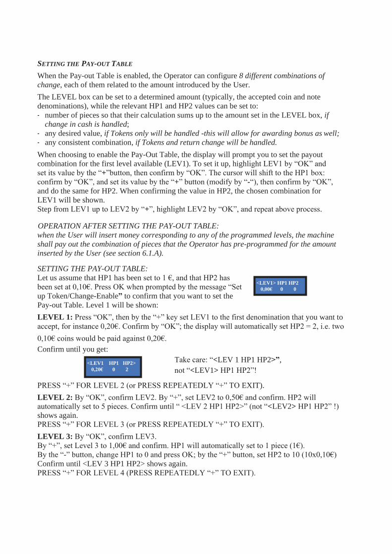
SETTING THE PAY-OUT TABLE
When the Pay-out Table is enabled, the Operator can configure 8 different combinations of
change, each of them related to the amount introduced by the User.
The LEVEL box can be set to a determined amount (typically, the accepted coin and note
denominations), while the relevant HP1 and HP2 values can be set to:
- number of pieces so that their calculation sums up to the amount set in the LEVEL box, if
change in cash is handled;
- any desired value, if Tokens only will be handled -this will allow for awarding bonus as well;
- any consistent combination, if Tokens and return change will be handled.
When choosing to enable the Pay-Out Table, the display will prompt you to set the payout
combination for the first level available (LEV1). To set it up, highlight LEV1 by “OK” and
set its value by the “+”button, then confirm by “OK”. The cursor will shift to the HP1 box:
confirm by “OK”, and set its value by the “+” button (modify by “-“), then confirm by “OK”,
and do the same for HP2. When confirming the value in HP2, the chosen combination for
LEV1 will be shown.
Step from LEV1 up to LEV2 by “+”, highlight LEV2 by “OK”, and repeat above process.
OPERATION AFTER SETTING THE PAY-OUT TABLE:
when the User will insert money corresponding to any of the programmed levels, the machine
shall pay out the combination of pieces that the Operator has pre-programmed for the amount
inserted by the User (see section 6.1.A).
SETTING THE PAY-OUT TABLE:
Let us assume that HP1 has been set to 1 €, and that HP2 has
been set at 0,10€. Press OK when prompted by the message “Set
up Token/Change-Enable” to confirm that you want to set the
Pay-out Table. Level 1 will be shown:
LEVEL 1: Press “OK”, then by the “+” key set LEV1 to the first denomination that you want to
accept, for instance 0,20€. Confirm by “OK”; the display will automatically set HP2 = 2, i.e. two
0,10€ coins would be paid against 0,20€.
Confirm until you get:
Take care: “<LEV 1 HP1 HP2>”,
not “<LEV1> HP1 HP2”! PRESS “+” FOR LEVEL 2 (or PRESS REPEATEDLY “+” TO EXIT).
LEVEL 2: By “OK”, confirm LEV2. By “+”, set LEV2 to 0,50€ and confirm. HP2 will automatically set to 5 pieces. Confirm until “ <LEV 2 HP1 HP2>” (not “<LEV2> HP1 HP2” !)
shows again.
PRESS “+” FOR LEVEL 3 (or PRESS REPEATEDLY “+” TO EXIT).
LEVEL 3: By “OK”, confirm LEV3.
By “+”, set Level 3 to 1,00€ and confirm. HP1 will automatically set to 1 piece (1€).
By the “-” button, change HP1 to 0 and press OK; by the “+” button, set HP2 to 10 (10x0,10€)
Confirm until <LEV 3 HP1 HP2> shows again.
PRESS “+” FOR LEVEL 4 (PRESS REPEATEDLY “+” TO EXIT).
<LEV1> HP1 HP2
0,00€ 0 0
<LEV1 HP1 HP2>
0,20€ 0 2

LEVEL 4: By “OK”, confirm LEV5.
By “+”, set Level 4 to 2,00€ and confirm. HP1 will automatically set to 2 pieces (2 x 1€).
You can set the pay-out table so as dispense any of the following combinations: (A) 2x1€ coins,
or (B) 1x1€ + 10x0,10€ coins, or else (C) 20x0,10€ coins.
Suppose choosing the combination (C): by the “-” button, change HP1 to 1 (1x1€ coins) and
press OK. By the “+” button, set HP2 to 10 (10x0,10€)
Confirm until <LEV 4 HP1 HP2> shows again.
PRESS “+” FOR LEVEL 5 (PRESS REPEATEDLY “+” TO EXIT).
LEVEL 5: By “OK”, confirm LEV4.
By “+”, set Level 5 to 5,00€ and confirm. HP1 will automatically set to 5 pieces (5 x 1€).
You can set the pay-out table so as dispense any of the following combinations: (A) 5x1€ coins,
or (B) 1x1€ + 40x0,10€ coins, or (C) 2x1€ + 30x0,10€ coins, or (E) 3x1 + 20x0,10€ coins, or (F)
4x1 + 10x0,10€ coins, or else (G) 50x0,10€.
Suppose choosing the combination (F): by the “-” button, change HP1 to 4 and press OK; by the
“+” button, set HP2 to 10 (10x0,10€)
Confirm until <LEV 5 HP1 HP2> shows again.
PRESS “+” FOR LEVEL 6 (PRESS REPEATEDLY “+” TO EXIT).
LEVEL 6: By “OK”, confirm LEV6.
By “+”, set Level 6 to 10,00€ and confirm. HP1 will automatically set to 10 pieces (10 x 1€).
You can set the pay-out table so as dispense any of the following combinations: (A) 10x1€ coins,
or (B) 9x1€ + 10x0,10€ coins, or (C) 8x1€ + 20x0,10€ coins, or ….. (N) 5x1 + 50x0,10€ coins,
and so on.
Suppose choosing the combination (B): by the “-” button, change HP1 to 9 and press OK; by the
“+” button, set HP2 to 10 (10x0,10€).
Confirm until <LEV 6 HP1 HP2> shows again. PRESS “+” FOR LEVEL 7 (PRESS REPEATEDLY “+” TO EXIT).
LEVEL 7: By “OK”, confirm LEV7.
By “+”, set Level 7 to 20,00€ and confirm.
You can set the pay-out table so as dispense any of the following combinations: (A) 20x1€ coins,
or (B) 19x1€ + 10x0,10€ coins, or (C) 18x1€ + 20x0,10€ coins, or … (M) 16x1€ + 40x0,10€, or
... (N) 5x1 + 50x0,10€, and so on. Suppose choosing the combination (M): by the “-” button,
change HP1 to 16 and press OK; by the “+” button, set HP2 to 40 (40x0,10€).
Confirm until <LEV 7 HP1 HP2> shows again.
PRESS “+” FOR LEVEL 8, OR PRESS OK UNTIL EXITING.
NOTICE: monitoring of level sensors is disabled by default. This means that the board does not
know when the hopper is empty, so it will send the pay-out command even if there are no coins
available. When the hopper runs out of coins during dispensing or at the end of payment, no
warning will be displayed. If the empty state is detected when powering the unit, this one shall
not accept any money.
If instead the monitoring has been enabled, and there are not enough coins in the hopper, the
display will warn that the hopper is empty. There will usually remain 20 coins approximately, so
as to complete the change payout.
PLEASE PAY ATTENTION: if the machine must be re-configured from token (or token +
return change) dispenser to coin changer, always do reset to DEFAULT
CONFIGURATION and RESET ACCOUNTS. Else, the bonus setting could produce
Accounts inconsistency.

DISPLAY
(*) DISPLAY LAST
EVENT
(*)
DATE AND TIME CASH
WITHDRAWAL
KEYS
WITHDRAWAL
RESTRICTED MENU
Key
initialized!
Antenna
initialized!
Enter PIN
0
7.3.5.C SET UP CASHLESS (only if the ACS reader is built-in)
If the unit is equipped with the ACS reader, it is possible to get access to useful functions:
Operation Master Card/Key
(black) for the
owner
Service Card/Key
(white) for the
manager
Operator
Card/Key
(yellow) 1. Initialize Service and Operator Card/Keys YES YES (only Operator’s) NO
2. Enable white Card/Key to collect money YES (from Menu) NO NO
3. Check Accounts (totals and partials) YES YES (partials only) NO
4. Print Accounts YES NO NO
5. Reset Accounts Data YES YES (partials only) NO
6. Reset of paid residual credit YES YES NO
7. Access to (optional) manual Refill YES YES NO
9. Collect money if Card/Key is enabled YES (max 500€) YES (max. 200 €) NO
The Master Card/Key allows to initialize the Service and the Operator Card/Key from the ACS reader.
Whenever the Master Card/Key or the Service Card/Key gets access to the Accounts menu, the
shown data get automatically downloaded in the Card/Key. Each Card/Key can contain up to 10
downloaded sets. These data sets can be read and stored in the PC via the ACR Programming
Station (K-P4N-000007) and software.
When entering this menu, the display will request to initialize the Card/Key reader (antenna).
Work out one 6 digits PIN code, write it down and keep it in a safe place.
Insert the Master Card/Key and press the OK button: you will be
prompted to enter the PIN code. Insert the 6 digits PIN. To enter each of
the 6 digits, make use of the UP and DOWN buttons. When the desired
character is displayed, confirm it by the OK button.
After entering the 6th character, the display will prompt for confirming the PIN code.
Enter it again: initialization of the Card/Key reader and of the Master
Card/Key will start. When finished, the confirmation message appears:
Insert the Service Card/Key: the machine 4-digit pin code (see section
9.3.13 Change PIN) will be requested; enter it to get the Service Card/Key
initialized. Once the process is complete, the confirmation appears:
To initialize Operator or User Card/Keys, exit the menu, put the Master Card/Key or the Service
Card/Key in the reader, and navigate the menu by “+” until finding RESTRICTED MENU: press OK,
and navigate to INITIALIZE CARD/KEYS, then press OK. Insert the Operator Card/Key and follow
the on-screen instructions:
Insert Operator
Card/Key (yellow)
Wait…… Remove the
initialized Card/Key
7.3.5.C.1 Restricted menu (reserved to owners of Master Card/Key and of Service Card/Key)
When inserting the Master or the Service Card/Key in the reader, the pushbuttons SEL and OK
light up green. By touching SEL, it is possible to navigate Accounts, Restricted Menu, and Exit.
By SEL, navigate to: and press OK. The following functions will be available:
INITIALIZE
(**) (***) ENABLE CASH
(**) Master can create Service and Operator
Keys; Service can create Operator Keys
(***) Reserved to Master only,
enabling Service Key only
Key
initialized! Do not remove the
key
Init. Operator
Key
(*) Reserved to
Master key only
Please wait
…….
Test GSM / GPRS
Module
(*) Insert User Code:
A
Insert User Code:
UC123CUH45
Set
User Code
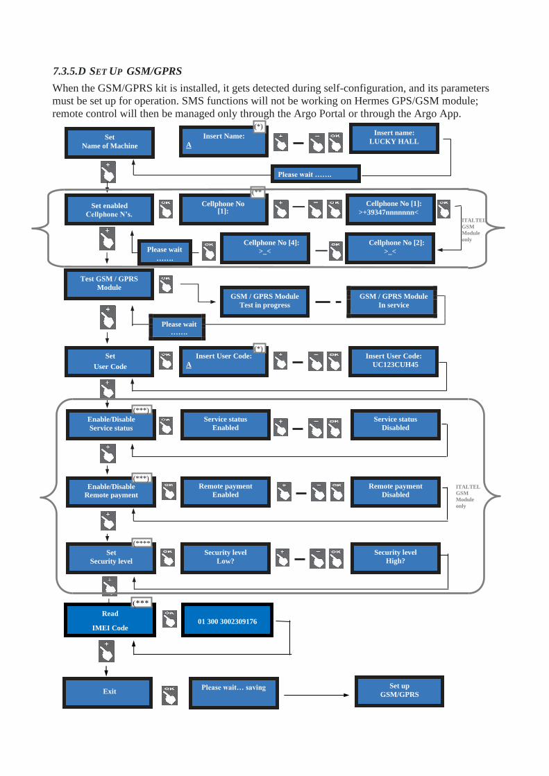
7.3.5.D SET UP GSM/GPRS
When the GSM/GPRS kit is installed, it gets detected during self-configuration, and its parameters
must be set up for operation. SMS functions will not be working on Hermes GPS/GSM module;
remote control will then be managed only through the Argo Portal or through the Argo App.
Set
Name of Machine
(*)
Insert Name:
A
(***)
Enable/Disable
Service status
(***) Enable/Disable
Remote payment
(****
Set
Security level
Security level
High?
Remote payment
Disabled
Service status
Disabled
Security level
Low?
Remote payment
Enabled
Service status
Enabled
(**
Cellphone No [1]:
>_<
Insert name:
LUCKY HALL
Please wait …….
Please wait… saving Set up
GSM/GPRS Exit
Cellphone No [2]:
>_<
Cellphone No [4]:
>_<
Cellphone No [1]:
>+39347nnnnnnn< Set enabled
Cellphone N’s.
GSM / GPRS Module
Test in progress
GSM / GPRS Module
In service
Please wait …….
ITALTEL
GSM
Module
only
ITALTEL
GSM
Module
only
Read
IMEI Code
01 300 3002309176

total
nnn,nn €
total
nnn,nn €
Exit EMPTY
HOPPER 2 EMPTY
HOPPER 1
EMPTY OUT
HOPPERS
LEV EURO PCS
2 10€ 11
LEV EURO PCS
1 2..3..10 € 1
(*) By the buttons + and - , locate the letter/digit, and press the OK button to confirm your choice; the cursor will automatically move to the next character. There are 16 characters in the machine name, and 10 in the User Code. After confirming the last character, the name or the /code you have typed gets automatically saved. In case you have purchased your subscription(s) when buying the machine (or the Hermes GSM module), no need to enter the User Code; it will be already present in the menu. (**) This function is available only in old GSM modules. By buttons + and - , locate the number you want to write, and press OK to confirm it; the cursor will automatically move to the next character. Once confirming the last digit, also confirm the whole number entered: it is proposed to enter the second number, and finally the third. (***) When the Service Status function is enabled, the machine can be put out of service by the relevant button in the ARGO Portal dashboard. Service can be restored by left-clicking on the same button. (****) When the Remote Payment function is active, and the Security Level has been set to Low, it is possible to command the machine to dispense an amount (in €) or a number of tokens (pieces) by the relevant command button in the ARGO Portal dashboard. When the Remote Payment function is active, and the Security Level has been set to High, it is still possible to command the machine to dispense an amount (in €) or a number of tokens (pieces) by the relevant command button in the ARGO Portal dashboard. However in this case, the display will prompt the Operator to enter the password: the Operator must then put his Refill key in the Refill lock (or his RFID key in its Reader),and enter the password by the buttons SEL (select each number) and OK (confirm each number).
7.3.6 EMPTY OUT THE HOPPERS
Use this function to make the selected hopper pay out all the contained coins / tokens. Once emptied
the first hopper, total dispensed amount shall be displayed. Press OK to go on with second hopper.
7.3.7 RESTORE DEFAULT CONFIGURATION
To use this sub-menu it is necessary to digit the PIN code.
WARNING: in case of reset, the system sets back to default configuration. The PIN code will be
reset to the default 0000 setting. Account records shall not be cancelled.
7.3.8 BONUS SET UP
This function will operate only if at least the hopper no. 1 is preset for paying tokens. Take care
to set up all hoppers parameters. Bonus function is disabled by default.
(*)Use Up key to modify
values
(*)
NOTICE: in case of any
mistake, do confirm the
wrong programmed data,
then re-program correctly.
PLEASSE WAIT
……….
Enter PIN 0…
RESTORE DEFAULT
CONFIGURATION
BONUS Bonus
ENABLE?
LEV EURO PCS
0 1€ 1 LEV EURO PCS
1 1€ 1
(*)
LEV EURO PCS
1 10€ 11
LEV EURO PCS
1 11..12.. € 1
LEV EURO PCS
2 10€ 11
LEV EURO PCS
1 10€ 1
Bonus
DISABLE?
Bonus settings
stored

7.3.9 LANGUAGE SETUP
English, French, German, Italian and Dutch are available as default. The Operatore can load other
languages and currencies by using the Alberici Babbel Software - please refer to the relevant
Babbel Software Instructions).
7.3.10 PROMO
It is possible to preset an advertisement on the display. Press OK:
Press again OK, the pointer will highlight the first digit: by UP or DOWN, choose the character that
you want to insert, then confirm by OK. The pointer will highlight the following digit.
Once digit no. 16 has been confirmed, the message gets stored.
7.3.11 MODIFY PIN
The PIN code allows to get access to the discretional menus of the system.
The PIN code is made up by 4 figures (each of them from 0 to 9: 10,000 combinations available).
If the entered PIN is not correct, the User is given another 4 tries before the board gets blocked-up
by its security interlock. The system can be started again by switching it off and on again.
ATTENTION: the default PIN code is 0000
The settings in the following menus can be modified by using the PIN code:
MODIFY PIN - RESET ACCOUNTS - RESTORE DEFAULT CONFIGURATION
To modify the existing PIN, press OK, and digit the old PIN code: to digit each code figure, first
use keys UP and DOWN to set each figure, then confirm it by OK. Once the 4th figure has been
confirmed, confirm by OK the whole old PIN:
To enter the new PIN code, use first the UP and DOWN keys to set each figure, then confirm it by
OK. Once the 4th figure has been confirmed, confirm by OK the whole new PIN.
As every single figure gets confirmed, an asterisk takes its place, so preserving secrecy.
NOTICE: when DEFAULT CONFIGURATION is restored, the PIN code gets reset to 0000.
LANGUAGE
SETUP
Seleziona lingua
ITALIANO
Choose language
ENGLISH
Waehlen Ihre Sprache
DEUTSCH
Digit text
-----------------------
-
New PIN
0
Enter
PIN
0
MODIFY PIN
+ / - + / -
Total filled
Amount: 2500€
Warn at 100
Euro available
+ / - + / -
Warn at 200
€ / Pcs available
Warn at 100
Euro available
MANUAL REFILL
Confirm?....
MANUAL REFILL
Confirm?....
E
M
P
T
Y
H
O
P
P
E
R
S
MANUAL REFILL
SET UP
MANUAL REFILL
SET UP
Reset of R
TURN OFF / ON DELAYED DISABLED ENABLE / DISABLE
REM. CR. RESET
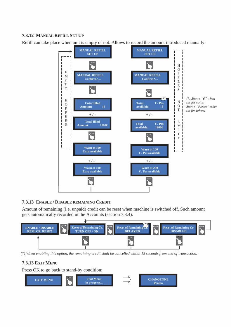
7.3.12 MANUAL REFILL SET UP
Refill can take place when unit is empty or not. Allows to record the amount introduced manually.
(*) Shows “€” when set for coins
Shows “Pieces” when
set for tokens
7.3.13 ENABLE / DISABLE REMAINING CREDIT
Amount of remaining (i.e. unpaid) credit can be reset when machine is switched off. Such amount
gets automatically recorded in the Accounts (section 7.3.4).
emaining Cr. +
(*) Reset of Remaining Cr.
Reset of Remaining Cr.
(*) When enabling this option, the remaining credit shall be cancelled within 15 seconds from end of transaction.
7.3.13 EXIT MENU
Press OK to go back to stand-by condition:
Total
available:
€ / Pcs
1800€
Warn at 100
€ / Pcs available
EXIT MENU Exit Menu
in progress… CHANGEONE
Promo
Enter filled
Amount: 1€
Total
available:
(*) € / Pcs
1€
H
O
P
P
E
R
S
N
O
T
E
M
P
T
Y

8 Messages
Display contrast
Should the contrast between the characters and the background be not convenient, adjust it as follows:
a. disconnect the cable from socket POWER IN/CCT of the pcb, and power up the machine;
b. hold down the “+” and “-“ buttons of the pcb at the same time, and plug the cable into socket
POWER IN/CCT; when the display starts flashing, release both buttons;
c. a prompt (in Italian language) will propose you to set the desired contrast level;
d. press the “+” button to increase the intensity of contrast/brightness. Intensity can be adjusted
between -15 and + 15. Standard values range between -1 and +5
e. once the desired degree of illumination has been reached, press the “ok” button;
f. power off the machine, then power it on again.
8.1 Messages from the display
8.1.1 Faulty operation:
The following warning:
is accompanied by the system check. For instance, the following sliding warnings:
stand for:
the coin acceptor is not connected, the note validator is faulty, and hopper 1 is properly working.
The following error messages can possibly appear:
the mentioned peripheral unit (coin acceptor, or note validator,
or Hopper, and so on is connected and functioning
the mentioned peripheral unit has been disconnected
the mentioned peripheral unit is connected but faulty
the Hopper is empty
The message
the inserted note is not enabled
means that coins have run out during the payout.
Switch power off, fill it up, and switch power on again:
the board will prompt the hopper to complete the payout.
...COIN ACCEPTOR…
.. DISCONNECTED ...
PTOR …. …. NOT
CTED … .… IN ER
TOR… …. HOPPE
ROR …. … CONN
R N° 1… …. HOPPE
TED …. … EMPT
(PERIPH. UNIT) IN ERROR
HOPPE
R
EMPTY
Remaining Credit
1 €
BANKNOTE
DISABLED
(PERIPH. UNIT)
DISCONNECTED
(PERIPH. UNIT)
CONNECTED
CHANGEONE
OUT OF SERVICE
8.1.2 Codice RI (RI Code) - (Control Board is blocked)
When this message appears, keep the 3 buttons behind the display pressed for 5 seconds.
The ‘Code RI’ message means that there has been an event that disabled the EPROM. If and when it
pops up, hold down the 3 OK, UP e DOWN keys at the same time for 5 seconds.
Such operation will reset the machine to its default configuration. It will then be necessary to re-
program the setup according to the needs.
In case that the ‘Code RI’ message pops up again after releasing the 3 keys, it means that the
EPROM has been damaged: it will be necessary to replace the board.
(PERIPH. UNIT)
EMPTY

8.2 Messages from the Note validator
8.2.1 BillyOne / OryOne Validator
During operation, the amount of consecutive red flashes produced by the entry slot indicates the
possible malfunctions (see chart below):
no of red flashes Description
1 Validator is open
2 Jammed banknote
3 Fraud attempt detected
5 Adjust optic sensors
7 Stacker full (OryOne Only)
9 Low power supply
11 Check operation of the encoder + efficiency of the validator motor
12 Check operation of the encoder + efficiency of the stacker motor (OryOne only)
14 ROM error
Solid yellow light Error in ccTalk communication. Check voltage level (12 or 24Vdc). Power the device off and on.
8.2.2 Front bezel flashing blue
When the front bezel flashes blue, it means that either the stacker has been removed, or the
detection sensor has gone faulty.
8.2.3 Fraud-fishing protection
The banknote reader is equipped with a security device that gets activated in the event of fishing
fraud attempts repeated over a period of time.
This device can be set through the dip-switch SW2 (DS-row on the Validator side) to operate in a
"soft" mode (* DS2 = ON) or in "extended" mode (** DS2 = OFF).
(**) Dip-Switch SW2 OFF
Attempt Validator reaction Do as described below
1th Remains in service -
2th Remains in service -
3th > error (3 red flashes) Reset (switch off then on)
4th > error (3 red flashes) Reset (switch off then on)
After the 5th fraud attempt (3 yellow flashes), it is necessary to wait for automatic restore
of service. Take care not to switch the device off.
NOTICE: no error status will be transmitted to the machine, so that the latter does not go out of
service, and will therefore continue to maintain the other functions working.
Any attempt at “fishing” will cause the note to be rejected, without showing any visible
signal.
(*) Dip-Switch SW2 ON
A
A
A
A
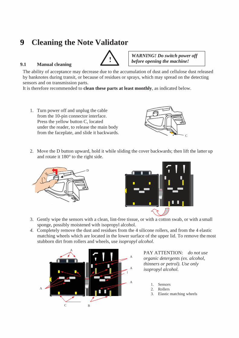
9 Cleaning the Note Validator
9.1 Manual cleaning
The ability of acceptance may decrease due to the accumulation of dust and cellulose dust released
by banknotes during transit, or because of residues or sprays, which may spread on the detecting
sensors and on transmission parts.
It is therefore recommended to clean these parts at least monthly, as indicated below.
1. Turn power off and unplug the cable
from the 10-pin connector interface.
Press the yellow button C, located
under the reader, to release the main body
from the faceplate, and slide it backwards.
2. Move the D button upward, hold it while sliding the cover backwards; then lift the latter up
and rotate it 180° to the right side.
3. Gently wipe the sensors with a clean, lint-free tissue, or with a cotton swab, or with a small
sponge, possibly moistened with isopropyl alcohol.
4. Completely remove the dust and residues from the 4 silicone rollers, and from the 4 elastic
matching wheels which are located in the lower surface of the upper lid. To remove the most
stubborn dirt from rollers and wheels, use isopropyl alcohol.
PAY ATTENTION: do not use
organic detergents (ex. alcohol,
thinners or petrol). Use only
isopropyl alcohol.
1. Sensors A 2. Rollers
3. Elastic matching wheels
C B
D
C
WARNING! Do switch power off
before opening the machine!

9.2 Clearing jammed banknotes
CAUTION! Turn off power before opening its upper lid.
Open the top cover by pressing D, and pull out
the stuck banknote (as well as any other objects
that will hinder the transit).
10. Disposal of the product
11. Terms of Guarantee
The manufacturer will fix malfunctions arising from production faults in this machine or parts of it within 12 months
from the date of sale.
All communications referring to guarantee repairs or replacements must be accompanied by the product serial number
and the copy of the sale invoice.
To obtain your guarantee repair, please send the part to the Dealer where you purchased the machine, together with the
following documents: - copy of the sale invoice
- delivery note stating “returned for guarantee repair”
- detailed report of the problem found and the circumstances in which it occurs.
Before sending the product, please get in touch with your Dealer or with Alberici S.p.a. (+39 051 944300); very
malfunctions can be fixed via a simple phone call, saving you costs and time.
Alberici S.p.a. will verify that warranty is applicable, i.e. that problem is not caused by:
- transport damages
- damages from incorrect installation or wrong configuration
- installation in premises or areas not complying with the prescribed safety requirements - intentional or unwilled tampering
- wrong or careless use or maintenance
- non-compliance with precautions prescribed (see Chapter 4. Caution)
- natural disasters, vandalisms, intentional or unintentional damage
Guarantee is considered automatically expired if outer and inner labels are missing.
Transport costs of repaired products are at the Customer’s charge.
12. Customer Service Alberici S.p.a. will be pleased to offer all the necessary information on use, ordinary maintenance and technical service.
Please call (+39) 051 944300 and specify if your request concerns information on use or technical support.
WARNING! DISPOSE OF ACCORDING TO THE GOVERNING LAW
IN YOUR COUNTRY!
This equipment may not be treated as household waste. Instead, it must be
handed over to the applicable collection point for the recycling of electric
and electronic equipment. By ensuring that this product is disposed of
correctly, you will help to prevent potential negative consequences for the
environment and human health, which could otherwise be caused by
inappropriate waste handling of this product.
For more detailed information about recycling of this product, please
contact the Dealer where you purchased this product.

ATTACHMENT: Spare parts List
HIRA 2 Maxi


HIRA 2 Midi


30
HIRA 2 Mini

31

32
___________________________
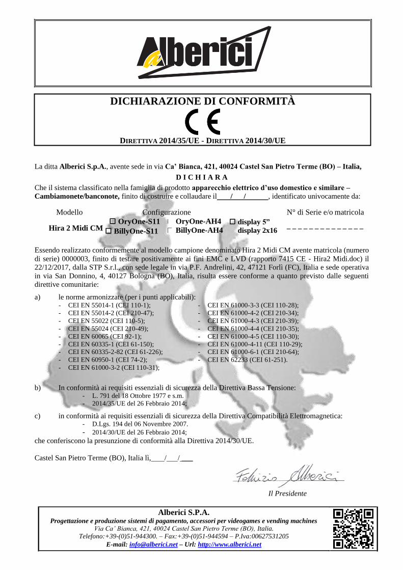
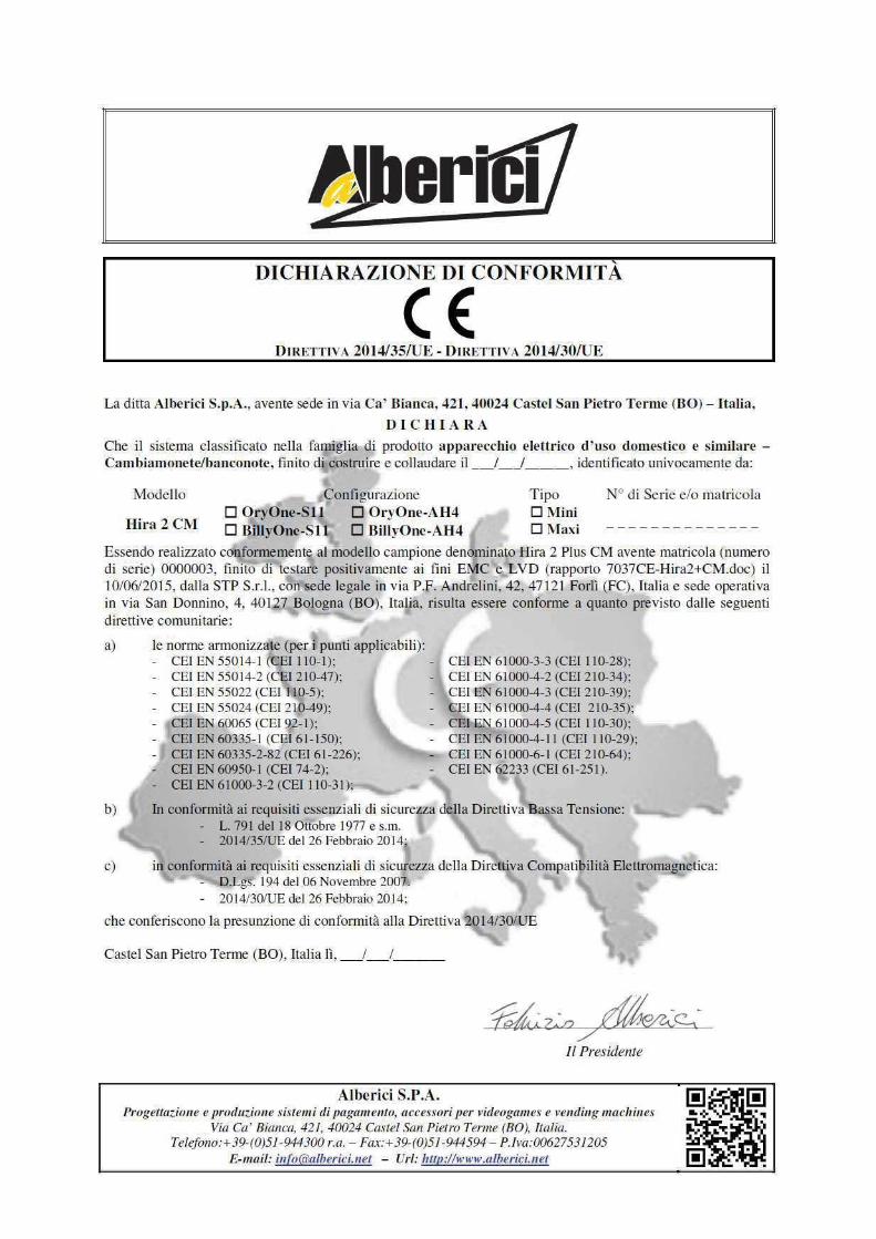
La ditta Alberici S.p.A., avente sede in via Ca’ Bianca, 421, 40024 Castel San Pietro Terme (BO) – Italia,
D I C H I A R A
Che il sistema classificato nella famiglia di prodotto apparecchio elettrico d’uso domestico e similare –
Cambiamonete/banconote, finito di costruire e collaudare il / / , identificato univocamente da:
Modello Configurazione N° di Serie e/o matricola
OryOne-S11
Hira 2 Midi CM BillyOne-S11
OryOne-AH4
BillyOne-AH4 display 5”
display 2x16 _ _ _ _ _ _ _ _ _ _ _ _ _ _
Essendo realizzato conformemente al modello campione denominato Hira 2 Midi CM avente matricola (numero
di serie) 0000003, finito di testare positivamente ai fini EMC e LVD (rapporto 7415 CE - Hira2 Midi.doc) il
22/12/2017, dalla STP S.r.l., con sede legale in via P.F. Andrelini, 42, 47121 Forlì (FC), Italia e sede operativa
in via San Donnino, 4, 40127 Bologna (BO), Italia, risulta essere conforme a quanto previsto dalle seguenti
direttive comunitarie:
a) le norme armonizzate (per i punti applicabili): - CEI EN 55014-1 (CEI 110-1);
- CEI EN 55014-2 (CEI 210-47);
- CEI EN 55022 (CEI 110-5);
- CEI EN 55024 (CEI 210-49);
- CEI EN 60065 (CEI 92-1);
- CEI EN 60335-1 (CEI 61-150); - CEI EN 60335-2-82 (CEI 61-226);
- CEI EN 60950-1 (CEI 74-2);
- CEI EN 61000-3-2 (CEI 110-31);
- CEI EN 61000-3-3 (CEI 110-28);
- CEI EN 61000-4-2 (CEI 210-34);
- CEI EN 61000-4-3 (CEI 210-39);
- CEI EN 61000-4-4 (CEI 210-35);
- CEI EN 61000-4-5 (CEI 110-30);
- CEI EN 61000-4-11 (CEI 110-29); - CEI EN 61000-6-1 (CEI 210-64);
- CEI EN 62233 (CEI 61-251).
b) In conformità ai requisiti essenziali di sicurezza della Direttiva Bassa Tensione: - L. 791 del 18 Ottobre 1977 e s.m.
- 2014/35/UE del 26 Febbraio 2014;
c) in conformità ai requisiti essenziali di sicurezza della Direttiva Compatibilità Elettromagnetica: - D.Lgs. 194 del 06 Novembre 2007.
- 2014/30/UE del 26 Febbraio 2014;
che conferiscono la presunzione di conformità alla Direttiva 2014/30/UE.
Castel San Pietro Terme (BO), Italia lì, / / ___
Il Presidente
DICHIARAZIONE DI CONFORMITÀ
DIRETTIVA 2014/35/UE - DIRETTIVA 2014/30/UE
Alberici S.P.A. Progettazione e produzione sistemi di pagamento, accessori per videogames e vending machines
Via Ca’ Bianca, 421, 40024 Castel San Pietro Terme (BO), Italia.
Telefono:+39-(0)51-944300. – Fax:+39-(0)51-944594 – P.Iva:00627531205
E-mail: [email protected] – Url: http://www.alberici.net

34

36

NOTICE
Alberici S.p.A. reserves the right to make changes to the equipment described and to its technical specifications at any time and without notice, in pursuit of the continual improvement of its products.
37

38