HIPOT Tester 19051/19052/19053/19054 User’s Manual · HIPOT Tester 19051/19052/19053 ... Any...
95
HIPOT Tester 19051/19052/19053/19054 User’s Manual Version 1.5 March 2005 P/N A11 000893
Transcript of HIPOT Tester 19051/19052/19053/19054 User’s Manual · HIPOT Tester 19051/19052/19053 ... Any...

HIPOT Tester
19051/19052/19053/19054
User’s Manual
Version 1.5
March 2005
P/N A11 000893
ii
Legal Notices
The information in this document is subject to change without notice.
Chroma ATE INC. makes no warranty of any kind with regard to this manual, including, but
not limited to, the implied warranties of merchantability and fitness for a particular purpose.
Chroma ATE INC. shall not be held liable for errors contained herein or direct, indirect,
special, incidental or consequential damages in connection with the furnishing, performance,
or use of this material.
CHROMA ATE INC. 66 Hwa-Ya 1 Rd., Hwa-Ya Technical Park, Kuei-Shan Hsiang, Taoyuan Hsien, Taiwan
Copyright Notices. Copyright 2003 Chroma ATE INC., all rights reserved. Reproduction,
adaptation, or translation of this document without prior written permission is prohibited,
except as allowed under the copyright laws.

iii
Warranty
All Chroma instruments are warranted against defects in material and workmanship for a
period of one year after date of shipment. Chroma agrees to repair or replace any
assembly or component found to be defective, under normal use during this period.
Chroma's obligation under this warranty is limited solely to repairing any such instrument,
which in Chroma's sole opinion proves to be defective within the scope of the warranty
when returned to the factory or to an authorized service center. Transportation to the
factory or service center is to be prepaid by purchaser. Shipment should not be made
without prior authorization by Chroma.
This warranty does not apply to any products repaired or altered by persons not authorized
by Chroma, or not in accordance with instructions furnished by Chroma. If the instrument
is defective as a result of misuse, improper repair, or abnormal conditions or operations,
repairs will be billed at cost.
Chroma assumes no responsibility for its product being used in a hazardous or dangerous
manner either alone or in conjunction with other equipment. High voltage used in some
instruments may be dangerous if misused. Special disclaimers apply to these instruments.
Chroma assumes no liability for secondary charges or consequential damages and in any
event, Chroma's liability for breach of warranty under any contract or otherwise, shall not
exceed the purchase price of the specific instrument shipped and against which a claim is
made.
Any recommendations made by Chroma for use of its products are based upon tests
believed to be reliable, but Chroma makes no warranty of the results to be obtained. This
warranty is in lieu of all other warranties, expressed or implied, and no representative or
person is authorized to represent or assume for Chroma any liability in connection with the
sale of our products other than set forth herein.
CHROMA ATE INC.
66 Hwa-Ya 1 Rd, Hwa-Ya Technical Park,
Kuei-Shan Hsiang, Taoyuan Hsien 333, Taiwan
Tel: 886-3-327-9999
Fax: 886-3-327-8898
http://www.chromaate.com
iv
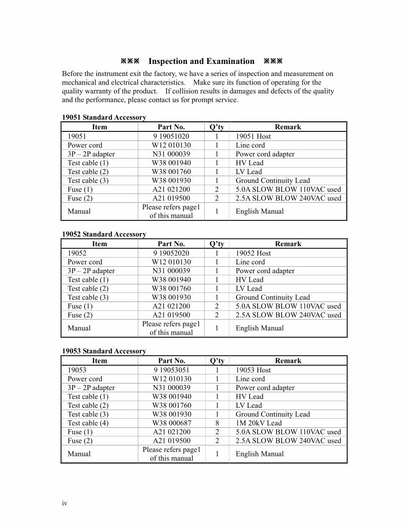
Inspection and Examination
Before the instrument exit the factory, we have a series of inspection and measurement on
mechanical and electrical characteristics. Make sure its function of operating for the
quality warranty of the product. If collision results in damages and defects of the quality
and the performance, please contact us for prompt service.
19051 Standard Accessory
Item Part No. Q’ty Remark
19051 9 19051020 1 19051 Host
Power cord W12 010130 1 Line cord
3P – 2P adapter N31 000039 1 Power cord adapter
Test cable (1) W38 001940 1 HV Lead
Test cable (2) W38 001760 1 LV Lead
Test cable (3) W38 001930 1 Ground Continuity Lead
Fuse (1) A21 021200 2 5.0A SLOW BLOW 110VAC used
Fuse (2) A21 019500 2 2.5A SLOW BLOW 240VAC used
Manual Please refers page1
of this manual 1 English Manual
19052 Standard Accessory
Item Part No. Q’ty Remark
19052 9 19052020 1 19052 Host
Power cord W12 010130 1 Line cord
3P – 2P adapter N31 000039 1 Power cord adapter
Test cable (1) W38 001940 1 HV Lead
Test cable (2) W38 001760 1 LV Lead
Test cable (3) W38 001930 1 Ground Continuity Lead
Fuse (1) A21 021200 2 5.0A SLOW BLOW 110VAC used
Fuse (2) A21 019500 2 2.5A SLOW BLOW 240VAC used
Manual Please refers page1
of this manual 1 English Manual
19053 Standard Accessory
Item Part No. Q’ty Remark
19053 9 19053051 1 19053 Host
Power cord W12 010130 1 Line cord
3P – 2P adapter N31 000039 1 Power cord adapter
Test cable (1) W38 001940 1 HV Lead
Test cable (2) W38 001760 1 LV Lead
Test cable (3) W38 001930 1 Ground Continuity Lead
Test cable (4) W38 000687 8 1M 20kV Lead
Fuse (1) A21 021200 2 5.0A SLOW BLOW 110VAC used
Fuse (2) A21 019500 2 2.5A SLOW BLOW 240VAC used
Manual Please refers page1
of this manual 1 English Manual

v
19054 Standard Accessory
Item Part No. Q’ty Remark
19054 9 19054010 1 19054 Host
Power cord W12 010130 1 Line cord
3P – 2P adapter N31 000039 1 Power cord adapter
Test cable (1) W38 001940 1 HV Lead
Test cable (2) W38 001760 1 LV Lead
Test cable (3) W38 001930 1 Ground Continuity Lead
Test cable (4) W38 000687 4 1M 20kV Lead
Fuse (1) A21 021200 2 5.0A SLOW 110VAC used
Fuse (2) A21 019500 2 2.5A SLOW 240VACused
Manual Please refers page1
of this manual 1 English Manual
Note: When order the accessories, just name item and part no..
Optional Accessory
Item Part No. Q’ty Remark
Print Board 9 19051099 1 19050 series
GP-IB Interface 9 19050899 1 19050 GP-IB Interface
GP-IB link cable 1M Y91 013555 1 For connecting computer control
GP-IB link cable 2M Y91 013556 1 For connecting computer control
RS232 link cable W38 844000 1 1.8M 9F 9M
vi
The Danger of Operating
1. When the instrument is under output voltage, please don’t touch test area or you may
shock hazard and result in death.
Please obey the following items.
Make sure the grounding cable is connected correctly and using the standard power
cord.
Don’t touch the output terminal.
Don’t touch test cable of connecting test termination.
Don’t touch test termination object.
Don’t touch any charge component of connecting output terminal.
As the instrument end the test or turn off output, please don’t touch test unit
immediately.
2. The shock accidents are usually occurred on the following conditions.
The grounding terminal of the instrument doesn’t connect correctly.
Do not use insulation glove for testing.
After test is completed to touch test unit immediately.
3. Remote Control for the instrument: This instrument provided with remote control,
normally using the external signal to control to high voltage output. For safety reasons
and prevent from hazards, please exactly follow instructions below while using remote
control.
Unexpected high voltage output may exist. Make sure if this instrument is under
testing/remote controlling before access to the probes.
When the instrument is under testing/operating, any access to DUT, test cable and
probe output terminal are prohibited, both for the operator/service personnel.
Normally remote control of this instrument is controlled by the high voltage test bar.
However, using of other control circuit is also possible. For safety reasons and
prevent from hazards, please notice that unintentional access to the control test bar
or bridging the control circuit to high voltage terminal and test cables may cause
hazards. Please keep this terminal/control from unintentional bridging/access to
avoid danger.
vii
Storage. Freight. Maintenance. Disposal
Storage When don’t use the device, please pack it properly and store under a good environment.
(The packing is no needed when the device under appropriate environment.)
Freight
Please use the original packing material when move the device. If the packing material is
missing, please use the equivalent buffer material to pack and mark it fragile and waterproof
etc to avoid the device damage during movement. The device belongs to precise
equipment, please uses qualified transportation as possible. And avoid heavy hitting etc to
damage the device.
Maintenance There is no maintenance operation for the general user. (Except for the note in the manual.)
Please contact our company or agent when the device occurred the user judgment abnormal.
Don’t maintain by yourself to avoid occurred unnecessary danger and serious damage to the
device.
Disposal When the device in badly condition and can’t be used or repaired, please discard it
according to your company disposal procedures or local legal procedures. Don’t discard
arbitrary to avoid polluting environment.

viii
Revision History
The following lists the additions, deletions and modifications in this manual at each
revision.
Date Version Revised Sections Sep. 2003 1.0 Modify “Inspection and Examination”
“Notice Items before Use”
“Rear Panel Description”
“Insulation Resistance Mode Resistor Calibration”
Oct. 2003 1.1 Modify “Specifications”
March 2004 1.2 Modify “The Danger of Operating”
“Specifications”
“Notice Items before Use”
“Rear Panel Description”
“Preset Parameter Setting”
Sep. 2004 1.3 Modify “Specifications”
“Notice Items before Use”
“Front Panel Description”
“Rear Panel Description”
“Preset Parameter Setting”
“PROGRAM Setting”
“How to Process Test”
“Remote Command Summary”
“Error Messages”
Dec. 2004 1.4 Modify “Introduction”
“PROGRAM Setting”
“How to Process Test”
“Remote Command Summary”
“Maintenance”
March 2005 1.5 − Add the note description to the displayed menu for switching in
OS Test Procedure section.

HIPOT Tester 19051/19052/19053/19054 User’s Manual
ix
Table of Contents 1. Introduction .................................................................................................................. 1-1
1.1 An Overview of Product.............................................................................. 1-1
1.2 Features....................................................................................................... 1-1
2. Specifications (18°°°°C ∼∼∼∼ 28°°°°C RH ≤≤≤≤ 70%) ................................................................... 2-1
3. Notice Items before Use ................................................................................................ 3-1
4. Panel Description.......................................................................................................... 4-1 4.1 Front Panel.................................................................................................. 4-1
4.2 Rear Panel ................................................................................................... 4-2
4.3 Notice Items and Procedures before Operation ............................................ 4-4
4.4 System Parameter Setting ............................................................................ 4-4 4.4.1 How to Enter System Parameter Setting Menu.......................................................... 4-4 4.4.2 Operation Methods..................................................................................................... 4-5
4.5 Test Parameter and Memory Management of Test Preset Parameter............. 4-5 4.5.1 How to Enter Memory Management Menu ............................................................... 4-5 4.5.2 How to Select a Set of Memory ................................................................................. 4-6 4.5.3 Delete Memory........................................................................................................... 4-6 4.5.4 Read Memory............................................................................................................. 4-7 4.5.5 Store Memory............................................................................................................. 4-7
4.6 Preset Parameter Setting.............................................................................. 4-7 4.6.1 How to Enter Testing Preset Parameter Setting Menu ............................................... 4-7 4.6.2 Operation Methods..................................................................................................... 4-8
4.7 PROGRAM Setting..................................................................................... 4-9 4.7.1 Test Procedure Setting................................................................................................ 4-9 4.7.2 Select Test Mode ...................................................................................................... 4-10 4.7.3 SMART KEY Operation Methods ........................................................................... 4-10 4.7.4 Each Parameter Setting Data Description ................................................................ 4-10
4.8 How to Process Test .................................................................................. 4-12 4.8.1 Offset Value Calibration Confirmation of Test Cable .............................................. 4-12 4.8.2 Connecting DUT Methods ....................................................................................... 4-12 4.8.3 Test Procedure (AC / DC / IR / OS)......................................................................... 4-13 4.8.4 Auto Range............................................................................................................... 4-15
4.9 KEY LOCK Function................................................................................ 4-16 4.9.1 KEY LOCK Setting Method .................................................................................... 4-16 4.9.2 KEY LOCK Release Method ................................................................................... 4-16
4.10 Setting User Password............................................................................... 4-17
4.11 Remote Control ......................................................................................... 4-17
4.12 Output Signal ............................................................................................ 4-19
4.13 Scan Test ................................................................................................... 4-19
5. GPIB Operation Description (Option)......................................................................... 5-1 5.1 Guide .......................................................................................................... 5-1
5.2 Interface Specification................................................................................. 5-1 5.2.1 Adaptable Standard .................................................................................................... 5-1 5.2.2 Interface Capability .................................................................................................... 5-1 5.2.3 Using Code................................................................................................................. 5-1
5.3 GPIB Related Panel Descriptions ................................................................ 5-2 5.3.1 Address Setting .......................................................................................................... 5-2 5.3.2 Remote / Local ........................................................................................................... 5-2
HIPOT Tester 19051/19052/19053/19054 User’s Manual
x
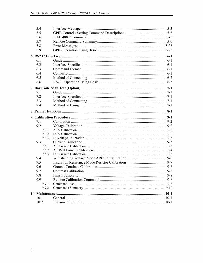
5.4 Interface Message........................................................................................ 5-3
5.5 GPIB Control / Setting Command Descriptions ........................................... 5-3
5.6 IEEE 488.2 Command................................................................................. 5-5
5.7 Remote Command Summary....................................................................... 5-6
5.8 Error Messages.......................................................................................... 5-23
5.9 GPIB Operation Using Basic ..................................................................... 5-25
6. RS232 Interface ............................................................................................................ 6-1 6.1 Guide .......................................................................................................... 6-1
6.2 Interface Specification................................................................................. 6-1
6.3 Command Format........................................................................................ 6-1
6.4 Connector.................................................................................................... 6-1
6.5 Method of Connecting................................................................................. 6-2
6.6 RS232 Operation Using Basic ..................................................................... 6-3
7. Bar Code Scan Test (Option)........................................................................................ 7-1 7.1 Guide .......................................................................................................... 7-1
7.2 Interface Specification................................................................................. 7-1
7.3 Method of Connecting................................................................................. 7-1
7.4 Method of Using ......................................................................................... 7-1
8. Printer Function ........................................................................................................... 8-1
9. Calibration Procedure .................................................................................................. 9-1 9.1 Calibration .................................................................................................. 9-2
9.2 Voltage Calibration...................................................................................... 9-2 9.2.1 ACV Calibration ........................................................................................................ 9-2 9.2.2 DCV Calibration ........................................................................................................ 9-2 9.2.3 IR Voltage Calibration................................................................................................ 9-3
9.3 Current Calibration...................................................................................... 9-3 9.3.1 AC Current Calibration .............................................................................................. 9-3 9.3.2 AC Real Current Calibration...................................................................................... 9-4 9.3.3 DC Current Calibration .............................................................................................. 9-5
9.4 Withstanding Voltage Mode ARCing Calibration......................................... 9-6
9.5 Insulation Resistance Mode Resistor Calibration ......................................... 9-7
9.6 Ground Continue Calibration....................................................................... 9-8
9.7 Contrast Calibration .................................................................................... 9-8
9.8 Finish Calibration........................................................................................ 9-8
9.9 Remote Calibration Command .................................................................... 9-8 9.9.1 Command List ............................................................................................................ 9-8 9.9.2 Commands Summary ............................................................................................... 9-10
10. Maintenance.............................................................................................................. 10-1 10.1 General...................................................................................................... 10-1
10.2 Instrument Return...................................................................................... 10-1
Introduction
1-1
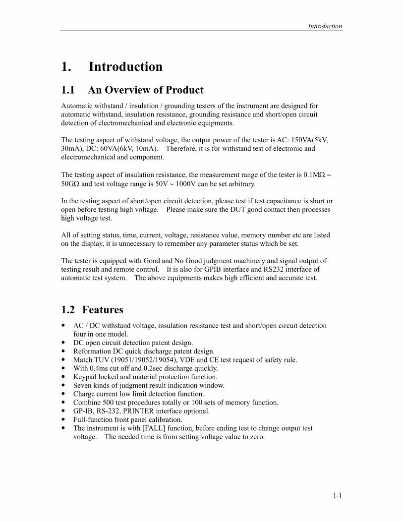
1. Introduction
1.1 An Overview of Product
Automatic withstand / insulation / grounding testers of the instrument are designed for
automatic withstand, insulation resistance, grounding resistance and short/open circuit
detection of electromechanical and electronic equipments.
The testing aspect of withstand voltage, the output power of the tester is AC: 150VA(5kV,
30mA), DC: 60VA(6kV, 10mA). Therefore, it is for withstand test of electronic and
electromechanical and component.
The testing aspect of insulation resistance, the measurement range of the tester is 0.1MΩ ∼
50GΩ and test voltage range is 50V ∼ 1000V can be set arbitrary.
In the testing aspect of short/open circuit detection, please test if test capacitance is short or
open before testing high voltage. Please make sure the DUT good contact then processes
high voltage test.
All of setting status, time, current, voltage, resistance value, memory number etc are listed
on the display, it is unnecessary to remember any parameter status which be set.
The tester is equipped with Good and No Good judgment machinery and signal output of
testing result and remote control. It is also for GPIB interface and RS232 interface of
automatic test system. The above equipments makes high efficient and accurate test.
1.2 Features
AC / DC withstand voltage, insulation resistance test and short/open circuit detection
four in one model.
DC open circuit detection patent design.
Reformation DC quick discharge patent design.
Match TUV (19051/19052/19054), VDE and CE test request of safety rule.
With 0.4ms cut off and 0.2sec discharge quickly.
Keypad locked and material protection function.
Seven kinds of judgment result indication window.
Charge current low limit detection function.
Combine 500 test procedures totally or 100 sets of memory function.
GP-IB, RS-232, PRINTER interface optional.
Full-function front panel calibration.
The instrument is with [FALL] function, before ending test to change output test
voltage. The needed time is from setting voltage value to zero.

Specifications
2-1
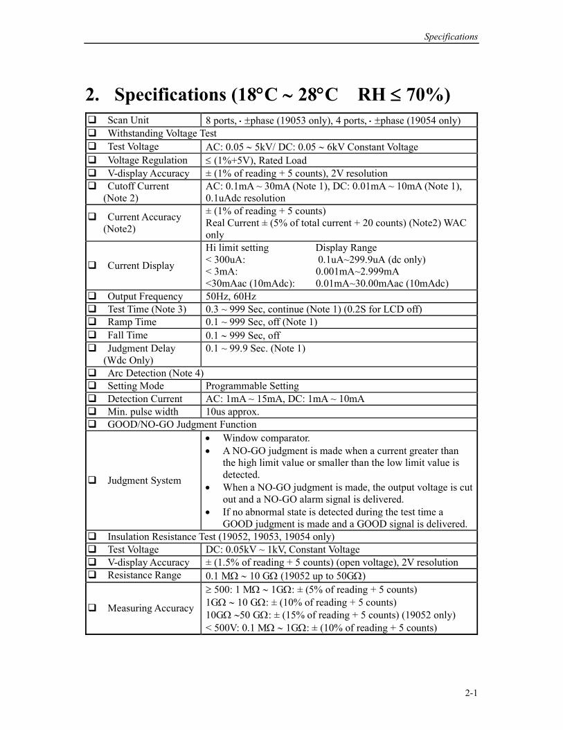
2. Specifications (18°°°°C ∼∼∼∼ 28°°°°C RH ≤≤≤≤ 70%) Scan Unit 8 ports, ⋅⋅⋅⋅ ±phase (19053 only), 4 ports, ⋅⋅⋅⋅ ±phase (19054 only)
Withstanding Voltage Test
Test Voltage AC: 0.05 ∼ 5kV/ DC: 0.05 ∼ 6kV Constant Voltage
Voltage Regulation ≤ (1%+5V), Rated Load
V-display Accuracy ± (1% of reading + 5 counts), 2V resolution
Cutoff Current
(Note 2)
AC: 0.1mA ~ 30mA (Note 1), DC: 0.01mA ~ 10mA (Note 1),
0.1uAdc resolution
Current Accuracy
(Note2)
± (1% of reading + 5 counts)
Real Current ± (5% of total current + 20 counts) (Note2) WAC
only
Current Display
Hi limit setting Display Range
< 300uA: 0.1uA~299.9uA (dc only)
< 3mA: 0.001mA~2.999mA
<30mAac (10mAdc): 0.01mA~30.00mAac (10mAdc)
Output Frequency 50Hz, 60Hz
Test Time (Note 3) 0.3 ~ 999 Sec, continue (Note 1) (0.2S for LCD off)
Ramp Time 0.1 ~ 999 Sec, off (Note 1)
Fall Time 0.1 ∼ 999 Sec, off
Judgment Delay
(Wdc Only)
0.1 ~ 99.9 Sec. (Note 1)
Arc Detection (Note 4)
Setting Mode Programmable Setting
Detection Current AC: 1mA ~ 15mA, DC: 1mA ~ 10mA
Min. pulse width 10us approx.
GOOD/NO-GO Judgment Function
Judgment System
• Window comparator.
• A NO-GO judgment is made when a current greater than
the high limit value or smaller than the low limit value is
detected.
• When a NO-GO judgment is made, the output voltage is cut
out and a NO-GO alarm signal is delivered.
• If no abnormal state is detected during the test time a
GOOD judgment is made and a GOOD signal is delivered.
Insulation Resistance Test (19052, 19053, 19054 only)
Test Voltage DC: 0.05kV ~ 1kV, Constant Voltage
V-display Accuracy ± (1.5% of reading + 5 counts) (open voltage), 2V resolution
Resistance Range 0.1 MΩ ∼ 10 GΩ (19052 up to 50GΩ)
Measuring Accuracy
≥ 500: 1 MΩ ∼ 1GΩ: ± (5% of reading + 5 counts)
1GΩ ∼ 10 GΩ: ± (10% of reading + 5 counts)
10GΩ ∼50 GΩ: ± (15% of reading + 5 counts) (19052 only)
< 500V: 0.1 MΩ ∼ 1GΩ: ± (10% of reading + 5 counts)

HIPOT Tester 19051/19052/19053/19054 User’s Manual
2-2
Secure Protection Function
Fast Output Cut-off 0.4mS typical after NG happen
Fast Discharge 0.2S, Typical
Ground Fault
Interrupt
0.5mA ± 0.25mAac (ON), OFF
Continuity Check 1Ω ± 0.2Ω, ON/OFF
Panel Operation Lock YES
Memory Storage
Memories, Steps 99 steps or 99 groups for total 500 memory locations
GO/NG Judgment Window
Indication, Alarm
GO: (Short Sound)
NG: W-Arc, W-Hi, W-Lo, IR-Lo, IR-Hi, GFI, Continuity-fail
(Long Sound)
Remote Connector
Rear Panel 9 Pin
D-type Connector
Input: Start, Stop, Interrupt (at 11 pin terminal block)
Output: Under test, Pass, Fail
TEST/RESET
Control
Low - active control, (24V open voltage typical).
Input requirements
Input time duration: 20msec. approx.
The above input circuits are not isolated from other internal
circuits.
Options
Interface Card
GP-IB Interface Talk, Listen all function
RS232 (standard
option)
Baud rate: 300 ~ 19200, data bits: 8, stop bit: 1
Ambient Temperature and Relative Humidity
Specifications range 18 to 28°C (64 to 82°F), ≤ 70% RH.
Operable range Maximum relative humidity 80% for temperature up to 31°C
(88°F). Decreasing linearly to 50% relative humidity at 40° C
(104°F)
Storage range -10 to 60°C (-14 to 140°F), ≤ 80% RH.
Power Requirement
Line Voltage AC 100V, 120V, 220V ± 10%, 240V +5 -10%
Frequency 50 or 60 Hz
Power No load: < 100W
Consumption With rated load: 500W max.
Dimension 320W x 105H x 400D mm
Weight 19051, 19052: 14kg approx.
19053, 19054: 15kg approx.
Specifications
2-3
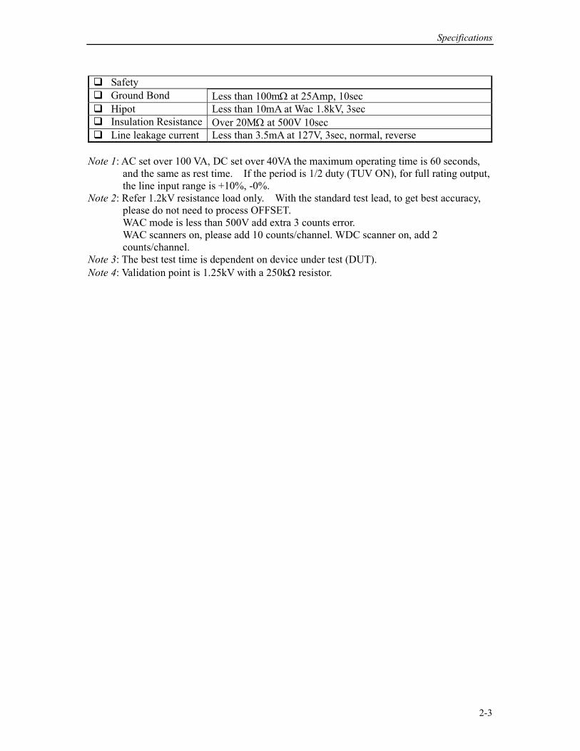
Safety
Ground Bond Less than 100mΩ at 25Amp, 10sec
Hipot Less than 10mA at Wac 1.8kV, 3sec
Insulation Resistance Over 20MΩ at 500V 10sec
Line leakage current Less than 3.5mA at 127V, 3sec, normal, reverse
Note 1: AC set over 100 VA, DC set over 40VA the maximum operating time is 60 seconds,
and the same as rest time. If the period is 1/2 duty (TUV ON), for full rating output,
the line input range is +10%, -0%.
Note 2: Refer 1.2kV resistance load only. With the standard test lead, to get best accuracy,
please do not need to process OFFSET.
WAC mode is less than 500V add extra 3 counts error.
WAC scanners on, please add 10 counts/channel. WDC scanner on, add 2
counts/channel.
Note 3: The best test time is dependent on device under test (DUT).
Note 4: Validation point is 1.25kV with a 250kΩ resistor.

Notice Items before Use
3-1
3. Notice Items before Use The tester is with high voltage output up to 6KV sending to external test. It may occur
injury and death result from error operation. Please peruse notice item of this chapter and
remember to avoid accident.
1. Shock Hazard For preventing shock be occurred. Before using the tester, put on insulation glove firstly
and then running function related to electricity.
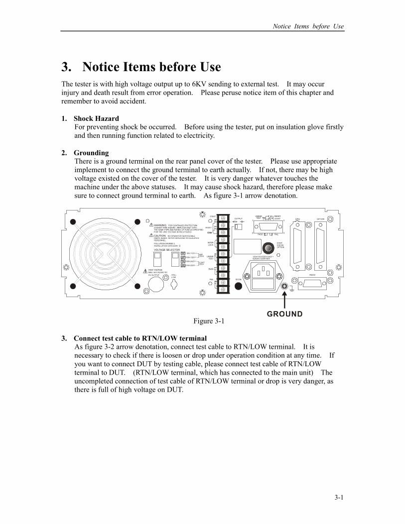
2. Grounding There is a ground terminal on the rear panel cover of the tester. Please use appropriate
implement to connect the ground terminal to earth actually. If not, there may be high
voltage existed on the cover of the tester. It is very danger whatever touches the
machine under the above statuses. It may cause shock hazard, therefore please make
sure to connect ground terminal to earth. As figure 3-1 arrow denotation.
Figure 3-1
3. Connect test cable to RTN/LOW terminal As figure 3-2 arrow denotation, connect test cable to RTN/LOW terminal. It is
necessary to check if there is loosen or drop under operation condition at any time. If
you want to connect DUT by testing cable, please connect test cable of RTN/LOW
terminal to DUT. (RTN/LOW terminal, which has connected to the main unit) The
uncompleted connection of test cable of RTN/LOW terminal or drop is very danger, as
there is full of high voltage on DUT.
HIPOT Tester 19051/19052/19053/19054 User’s Manual
3-2
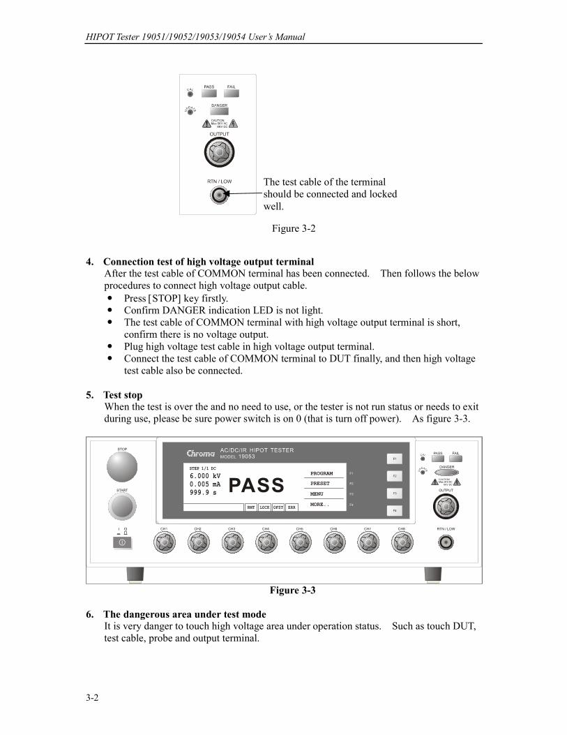
Figure 3-2
The test cable of the terminal
should be connected and locked
well.
4. Connection test of high voltage output terminal After the test cable of COMMON terminal has been connected. Then follows the below
procedures to connect high voltage output cable.
Press [STOP] key firstly.
Confirm DANGER indication LED is not light.
The test cable of COMMON terminal with high voltage output terminal is short,
confirm there is no voltage output.
Plug high voltage test cable in high voltage output terminal.
Connect the test cable of COMMON terminal to DUT finally, and then high voltage
test cable also be connected.
5. Test stop When the test is over the and no need to use, or the tester is not run status or needs to exit
during use, please be sure power switch is on 0 (that is turn off power). As figure 3-3.
Figure 3-3
6. The dangerous area under test mode It is very danger to touch high voltage area under operation status. Such as touch DUT,
test cable, probe and output terminal.
Notice Items before Use
3-3
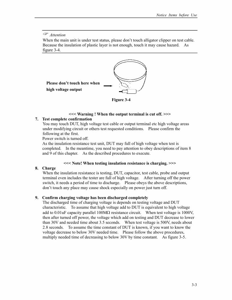
Attention
When the main unit is under test status, please don’t touch alligator clipper on test cable.
Because the insulation of plastic layer is not enough, touch it may cause hazard. As
figure 3-4.
Figure 3-4
Please don’t touch here when
high voltage output
<<< Warning ! When the output terminal is cut off. >>>
7. Test complete confirmation You may touch DUT, high voltage test cable or output terminal etc high voltage areas
under modifying circuit or others test requested conditions. Please confirm the
following at the first.
Power switch is turned off.
As the insulation resistance test unit, DUT may full of high voltage when test is
completed. In the meantime, you need to pay attention to obey descriptions of item 8
and 9 of this chapter. As the described procedures to execute.
<<< Note! When testing insulation resistance is charging. >>>
8. Charge When the insulation resistance is testing, DUT, capacitor, test cable, probe and output
terminal even includes the tester are full of high voltage. After turning off the power
switch, it needs a period of time to discharge. Please obeys the above descriptions,
don’t touch any place may cause shock especially on power just turn off.
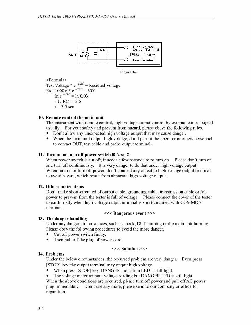
9. Confirm charging voltage has been discharged completely The discharged time of charging voltage is depends on testing voltage and DUT
characteristic. To assume that high voltage add to DUT is equivalent to high voltage
add to 0.01uF capacity parallel 100MΩ resistance circuit. When test voltage is 1000V,
then after turned off power, the voltage which add on testing and DUT decrease to lower
than 30V and needed time about 3.5 seconds. When test voltage is 500V, needs about
2.8 seconds. To assume the time constant of DUT is known, if you want to know the
voltage decrease to below 30V needed time. Please follow the above procedures,
multiply needed time of decreasing to below 30V by time constant. As figure 3-5.
HIPOT Tester 19051/19052/19053/19054 User’s Manual
3-4
1905x
Figure 3-5
<Formula>
Test Voltage * e –t/RC
= Residual Voltage
Ex.: 1000V * e –t/RC
= 30V
ln e –t/RC
= ln 0.03
- t / RC = -3.5
t = 3.5 sec
10. Remote control the main unit The instrument with remote control, high voltage output control by external control signal
usually. For your safety and prevent from hazard, please obeys the following rules.
Don’t allow any unexpected high voltage output that may cause danger.
When the main unit output high voltage, don’t permit the operator or others personnel
to contact DUT, test cable and probe output terminal.
11. Turn on or turn off power switch Note
When power switch is cut off, it needs a few seconds to re-turn on. Please don’t turn on
and turn off continuously. It is very danger to do that under high voltage output.
When turn on or turn off power, don’t connect any object to high voltage output terminal
to avoid hazard, which result from abnormal high voltage output.
12. Others notice items Don’t make short-circuited of output cable, grounding cable, transmission cable or AC
power to prevent from the tester is full of voltage. Please connect the cover of the tester
to earth firstly when high voltage output terminal is short-circuited with COMMON
terminal.
<<< Dangerous event >>>
13. The danger handling Under any danger circumstances, such as shock, DUT burning or the main unit burning.
Please obey the following procedures to avoid the more danger.
Cut off power switch firstly.
Then pull off the plug of power cord.
<<< Solution >>>
14. Problems Under the below circumstances, the occurred problem are very danger. Even press
[STOP] key, the output terminal may output high voltage.
When press [STOP] key, DANGER indication LED is still light.
The voltage meter without voltage reading but DANGER LED is still light.
When the above conditions are occurred, please turn off power and pull off AC power
plug immediately. Don’t use any more, please send to our company or office for
reparation.
Notice Items before Use
3-5
15. DANGER indication LED error
When press [START] key, there is already reading on the voltage meter and DANGER
LED is still not light. In the meantime, the indication LED may be error please turn off
immediately. Please send it to our company or office for reparation.
16. If the tester needs long time using under normal operation. Please notice the
following items. If the high limit setting value is 20.00mA (withstand voltage test), please notice its’
ambient temperature. When the ambient temperature is higher than 40°C, please stop
operation until it cools down to normal temperature.
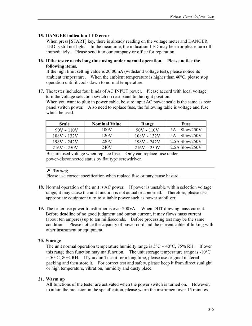
17. The tester includes four kinds of AC INPUT power. Please accord with local voltage
turn the voltage selection switch on rear panel to the right position.
When you want to plug in power cable, be sure input AC power scale is the same as rear
panel switch power. Also need to replace fuse, the following table is voltage and fuse
which be used.
Scale Nominal Value Range Fuse
90V ∼ 110V 100V 90V ∼ 110V 5A Slow/250V
108V ∼ 132V 120V 108V ∼ 132V 5A Slow/250V
198V ∼ 242V 220V 198V ∼ 242V 2.5A Slow/250V
216V ∼ 250V 240V 216V ∼ 250V 2.5A Slow/250V
Be sure used voltage when replace fuse. Only can replace fuse under
power-disconnected status by flat type screwdriver.
Warning
Please use correct specification when replace fuse or may cause hazard.
18. Normal operation of the unit is AC power. If power is unstable within selection voltage
range, it may cause the unit function is not actual or abnormal. Therefore, please use
appropriate equipment turn to suitable power such as power stabilizer.
19. The tester use power transformer is over 200VA. When DUT drawing mass current.
Before deadline of no good judgment and output current, it may flows mass current
(about ten amperes) up to ten milliseconds. Before processing test may be the same
condition. Please notice the capacity of power cord and the current cable of linking with
other instrument or equipment.
20. Storage
The unit normal operation temperature humidity range is 5°C ∼ 40°C, 75% RH. If over
this range then function may malfunction. The unit storage temperature range is -10°C
∼ 50°C, 80% RH. If you don’t use it for a long time, please use original material
packing and then store it. For correct test and safety, please keep it from direct sunlight
or high temperature, vibration, humidity and dusty place.
21. Warm up
All functions of the tester are activated when the power switch is turned on. However,
to attain the precision in the specification, please warm the instrument over 15 minutes.

HIPOT Tester 19051/19052/19053/19054 User’s Manual
3-6
22. Safety symbol
: There is lethal voltage on output terminal. Please peruse all safety
operation notice items.
: There is detailed explanation in the operation manual, please peruse the
descriptions of the manual.
: Protective grounding terminal for preventing electrical shock in case of
leakage to the cover. The terminal must be connected to ground before
operation of equipment.
Warning : Warning sign for preventing a procedure, practice or other conditions which
may result in injury or death of personnel if it is not rightly operated.
Caution : Warning sign for preventing a procedure, practice or other conditions which
may result in the instrument and other DUT abnormal.
Note : Note sign. Refer to the procedure, practice or other conditions, please
peruse particularly.
23. Warning signal of testing
"DANGER – HIGH VOLTAGE TEST IN PROGRESS, UNAUTHORIZED
PERSON KEEP AWAY"

Panel Description
4-1
4. Panel Description
4.1 Front Panel
Front panel includes several function areas which easy to use. This paragraph will introduce
each control and information on LCD to you.
Display Area Function key display area: Under different display menus, there are different function
descriptions. The right side of display has corresponding function keys (F1-F4). If the
description is blank, it means corresponding function is invalid.
State list : This list indicates the setting mode, the range of setting value and displays no
good state of testing result.
RMT : When this area is highlighted, it means the main unit is under Remote status.
That is the main unit controlled by PC through GPIB/RS232 connecting cable.
At the same time, all of keys are malfunction except for [STOP], [Local] and
[MORE..] Keys.
LOCK : When this area is highlighted, it means the main unit is under setting
parameter protected mode. The other mode can’t enter except for
"MEMORY", "TEST" and "KEY LOCK" modes.
OFST : When this area is highlighted, it means the main unit has been zeroed the
leakage current of test cable and test lead currently.
ERR : When this area is highlighted, it means there is unclear error in error queue.
Danger LED : The testing status indication LED. When LED is light, the tester is under
testing status. There is high voltage or mass current on testing terminal.
Don’t touch the testing terminal at the same time.
PASS LED : When this LED is light, it means DUT judge as PASS after testing.
FAIL LED : When this LED is light, it means DUT judge as FAIL after testing and then
cutting off the main unit output immediately. This LED keeps on light
HIPOT Tester 19051/19052/19053/19054 User’s Manual
4-2
until the main unit be pressed [STOP] key.
Key Area Power Switch : The switch provides AC power source which the tester is needed.
STOP Key : Reset key, after pressing this key the main unit return to standby testing
status immediately. That is cutting output and clear all of judgments
simultaneously.
START Key : After pressing this key, the main unit is under testing status. The testing
terminal has output and each judgment function starts simultaneously.
Cal-Enable : Calibration switch. This key is only for calibration before exiting
factory. A non-professional personnel using this function is prohibited
or may cause the product malfunction.
Function Keys: Function key. Under different display menus, there are different
functions. The right side of display has corresponding function
description. If the description is blank, it means corresponding function
key is invalid.
Terminal Area OUTPUT : High electric potential terminal of high voltage output. This terminal is
belong to high electric potential output, usually is high voltage output.
Therefore, this terminal is very dangerous. Don’t touch it when
DANGER LED is light, there is high voltage outputting.
RTN / LOW : The common test terminal. It’s a reference terminal when high voltage
test, it also a low electric potential terminal. This terminal is almost
equal to cover grounding terminal.
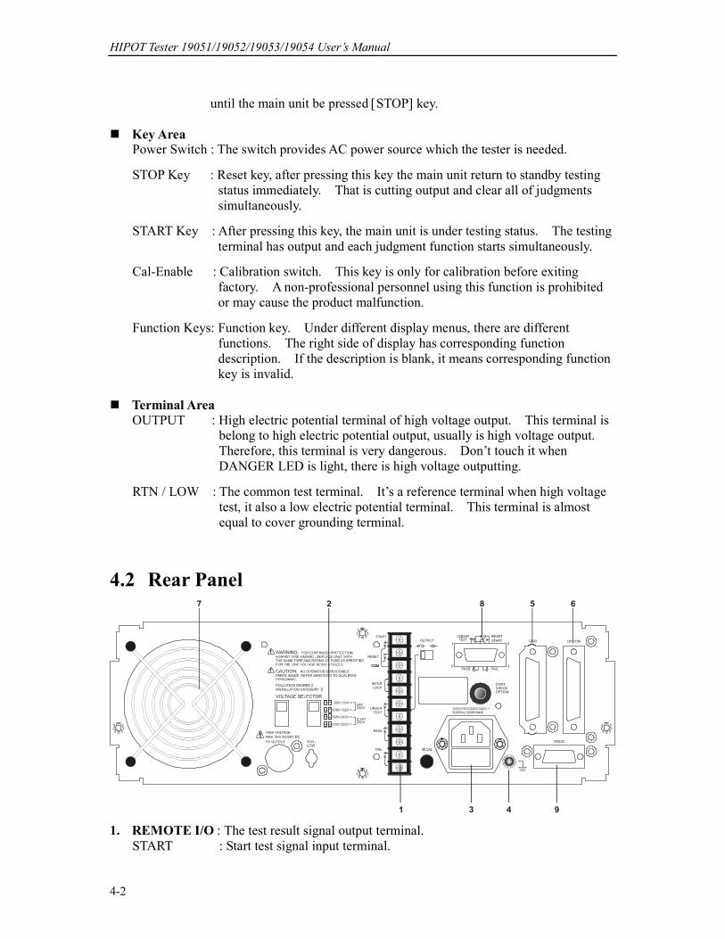
4.2 Rear Panel
1. REMOTE I/O : The test result signal output terminal.
START : Start test signal input terminal.
Panel Description
4-3
STOP : Stop test signal input terminal.
INTER LOCK : Output only when this two terminals are short circuit and high voltage.
UNDER TEST : When the tester is under test status, this output terminal will short circuit.
Control external signal by using this short condition. The junction
specification 115V AC current is lower than 0.3A action time.
This tester is under testing status until STOP is stopped.
PASS : When the tester judge DUT is PASS, this output terminal is short circuit.
Control external signal by using this short circuit condition. The
junction specification 115V AC current is lower than 0.3A.
The action time is 0.2sec ∼ 99.9sec. (Can be set)
FAIL : When the tester judge DUT is FAIL, this output terminal will be short
circuit. Control external signal by using this short condition. The
junction specification 115V AC current is lower than 0.3A.
The action time: From judging FAIL to STOP is stopped.
OUTPUT Switch: When toggles this switch to power symbol, UNDER TEST output
terminal will be short circuited under test status. When toggles this
switch to voltage symbol, UNDER TEST terminal outputs 24V under
test status. This function can be used with 3002B or 3002D and is for
controlling valve.
2. VOLTAGE SELECTOR Input Power Supply Range Switch Changing the tester inputted AC power. Using AC power has four kinds as below.
a. 90 ∼ 110V AC
b. 108 ∼ 132V AC
c. 198 ∼ 242V AC
d. 216 ∼ 250V AC
Switching this power switch by applying AC power and notice the change of fuse.
3. AC LINE: AC power socket and fuse holder.
A tri-cord power and fuse holder. Input AC power, which the tester is needed from AC
power socket. The detailed specification of using fuse please refers "Chapter 3 - Notice
Items Before Using" or descriptions of rear panel in this manual.
4. GROUND: Safety GND terminal. Please use adaptable implement to connect this
grounding terminal actually. If there is no grounding actually, the circuit with GND
terminal or other instruments connecting cable with GND terminal is short circuit. The
cover of tester may exist high voltage. This is very dangerous, anyone touch the tester
under the above status may cause damage. Therefore, it is necessary to connect safety
GND terminal to ground.
5. GPIB INTERFACE (Option)
This socket is for optional GIPB interface (IEEE-488-1978). The detailed descriptions,
please refers "Chapter 5 - Description of GPIB Interface" in this manual.
6. OPTION: This socket is the option PRINTER interface for the tester. The detailed
descriptions please refer chapter 8 of this manual.

HIPOT Tester 19051/19052/19053/19054 User’s Manual
4-4
7. FAN: The temperature control fan.
When the temperature reaches 50°C, fan opens automatically. When the temperature is
lower than 45°C, fan stops automatically.
8. 9 Pin D Connector
All of 9 pin D-Sub connector functions are the same as (1) Remote I/O.
9. RS232 Interface
This socket is the standard RS232 interface for the tester. GPIB and RS232 interface
can’t use simultaneously.
4.3 Notice Items and Procedures before Operation
1. Before plugging AC power cable, please confirm power that use firstly and description of
rear panel is match or not and power switch is OFF status.
2. Before turning on power, please peruse "Chapter 3 - Notice Items Before Using" and
remember it.
3. When turns on power, the tester will self-test. If there is abnormal condition, please
turns off switch and pulls off power cord immediately.
4.4 System Parameter Setting
4.4.1 How to Enter System Parameter Setting Menu
1. Under power on menu, press Function Key MENU the menu as the following:
1. MEMORY UP
2. SYSTEM
3. OPTION DOWN
4. CALIBRATION
5. KEY LOCK SELECT
SELECT FUNC. RMT LOCK OFST ERR EXIT
2. Move the highlighted to "SYSTEM" by Function Key UP, DOWN. Press Function Key
SELECT to enter system parameter setting menu is shown as the following:
Panel Description
4-5
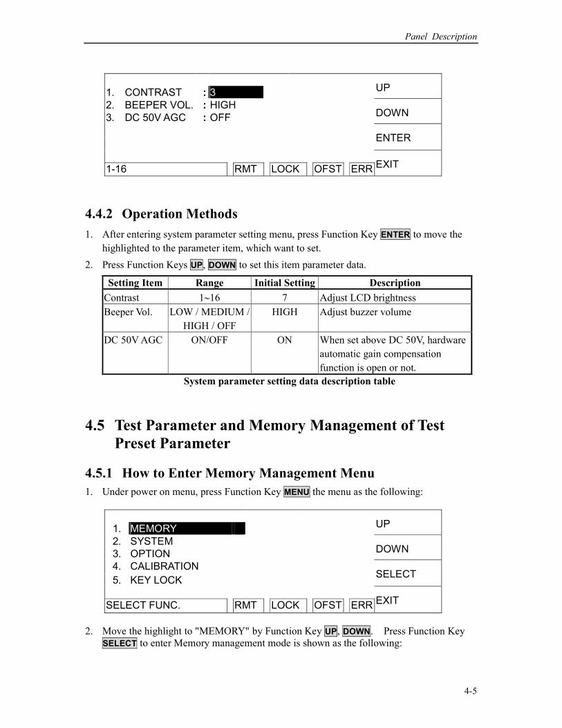
1. CONTRAST : 3 UP
2. BEEPER VOL. : HIGH
3. DC 50V AGC : OFF DOWN
ENTER
1-16 RMT LOCK OFST ERR EXIT
4.4.2 Operation Methods
1. After entering system parameter setting menu, press Function Key ENTER to move the
highlighted to the parameter item, which want to set.
2. Press Function Keys UP, DOWN to set this item parameter data.
Setting Item Range Initial Setting Description
Contrast 1∼16 7 Adjust LCD brightness
Beeper Vol. LOW / MEDIUM /
HIGH / OFF
HIGH Adjust buzzer volume
DC 50V AGC ON/OFF ON When set above DC 50V, hardware
automatic gain compensation
function is open or not.
System parameter setting data description table
4.5 Test Parameter and Memory Management of Test
Preset Parameter
4.5.1 How to Enter Memory Management Menu
1. Under power on menu, press Function Key MENU the menu as the following:
1. MEMORY UP
2. SYSTEM
3. OPTION DOWN
4. CALIBRATION
5. KEY LOCK SELECT
SELECT FUNC. RMT LOCK OFST ERR EXIT
2. Move the highlight to "MEMORY" by Function Key UP, DOWN. Press Function Key
SELECT to enter Memory management mode is shown as the following:

HIPOT Tester 19051/19052/19053/19054 User’s Manual
4-6
1. ( 0 ) STORE
2. ( 0 )
3. ( 0 ) RECALL
4. ( 0 )
5. ( 0 ) DELETE
SELE. MEMORY RMT LOCK OFST ERR EXIT
3. At this time, can read, store or delete this set memory by Function Key.
4. The value within ( ) means this set memory included test procedure number.
4.5.2 How to Select a Set of Memory
1. When the state list shows "SELECT MEMORY", move the highlighted to the memory
which want to manage by Function Key UP, DOWN. Press Function Key SELECT is
shown the following menu:
1. ( 0 ) UP
2. ( 0 )
3. ( 0 ) DOWN
4. ( 0 )
5. ( 0 ) SELECT
SELE. MEMORY RMT LOCK OFST ERR RETURN
2. At this time, follows Function Key instructions to read, store or delete this set of memory.
4.5.3 Delete Memory
If you want to delete test parameter data which be stored in memory, please follows the below
procedures to process.
1. Press Function Key DELETE when status bar shows [SELECT FUNC.].
2. Select the test parameter data of memory, which want to delete by using Function Key UP,
DOWN. Press Function Key DELETE and then show delete confirm window.
3. Press Function Key YES to confirm or press Function Key NO to cancel.
Panel Description
4-7
4.5.4 Read Memory
If there are many sets of test parameter values which be saved in main memory. Follow the
below procedures to recall test parameter.
1. Press Function Key RECALL when status bar shows [SELECT FUNC.].
2. Select the test parameter data of memory, which want to read by using Function Key UP,
DOWN.
3. Press Function Key SELECT and then show confirm window.
4. Press Function Key YES to confirm or press Function Key NO to cancel.
4.5.5 Store Memory
If you want to save test parameter data which be set in the memory. Please follows the
below procedures to process.
1. When status bar shows [SELECT FUNC.], press Function Key STORE.
2. Selecting the memory want to store by using Function Key UP, DOWN. Press Function
Key SELECT, the cursor become underscore blinking cursor.
3. At this time, input the memory name by using Function Key UP, DOWN.
4. By using Function Key ENTER to move the underscore blinking cursor to next character.
5. If press Function Key ENTER twice then will show a read confirmation window.
6. Press Function Key YES to confirm or press Function Key NO to cancel.
(Note: If there is covered data in the memory name, please be careful to confirm before
storing.)
4.6 Preset Parameter Setting
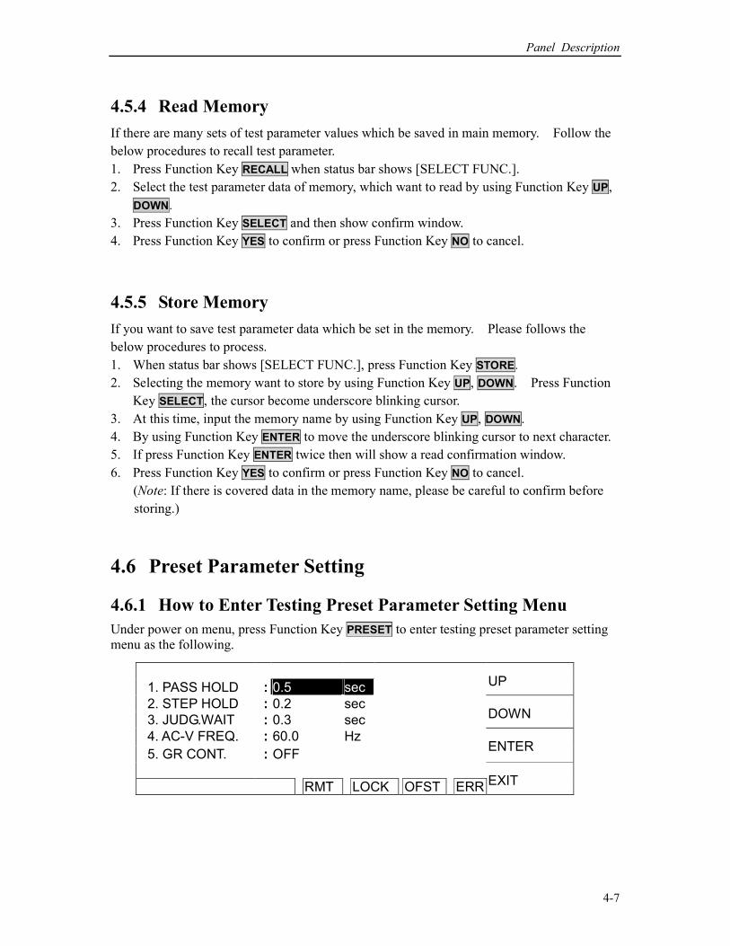
4.6.1 How to Enter Testing Preset Parameter Setting Menu
Under power on menu, press Function Key PRESET to enter testing preset parameter setting
menu as the following.
1. PASS HOLD : 0.5 sec UP
2. STEP HOLD : 0.2 sec
3. JUDG.WAIT : 0.3 sec DOWN
4. AC-V FREQ. : 60.0 Hz
5. GR CONT. : OFF ENTER
RMT LOCK OFST ERR EXIT
HIPOT Tester 19051/19052/19053/19054 User’s Manual
4-8
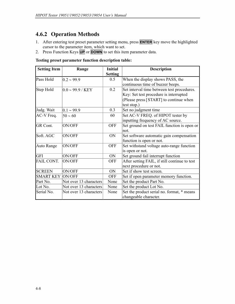
4.6.2 Operation Methods
1. After entering test preset parameter setting menu, press ENTER key move the highlighted
cursor to the parameter item, which want to set.
2. Press Function Keys UP or DOWN to set this item parameter data.
Testing preset parameter function description table:
Setting Item Range Initial
Setting
Description
Pass Hold 0.2 ∼ 99.9 0.5 When the display shows PASS, the
continuous time of buzzer beeps.
Step Hold 0.0 ∼ 99.9 / KEY 0.2 Set interval time between test procedures.
Key: Set test procedure is interrupted
(Please press [START] to continue when
test stop.)
Judg. Wait 0.1 ∼ 99.9 0.3 Set no judgment time
AC-V Freq. 50 ∼ 60 60 Set AC-V FREQ. of HIPOT tester by
inputting frequency of AC source.
GR Cont. ON/OFF OFF Set ground on test FAIL function is open or
not.
Soft. AGC ON/OFF ON Set software automatic gain compensation
function is open or not.
Auto Range ON/OFF OFF Set withstand voltage auto-range function
is open or not.
GFI ON/OFF ON Set ground fail interrupt function
FAIL CONT. ON/OFF OFF After setting FAIL, if still continue to test
next procedure or not.
SCREEN ON/OFF ON Set if show test screen.
SMART KEY ON/OFF OFF Set if open parameter memory function.
Part No. Not over 13 characters None Set the product Part No.
Lot No. Not over 13 characters None Set the product Lot No.
Serial No. Not over 13 characters None Set the product serial no. format, * means
changeable character.
Panel Description
4-9
4.7 PROGRAM Setting
4.7.1 Test Procedure Setting
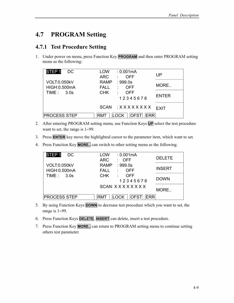
1. Under power on menu, press Function Key PROGRAM and then enter PROGRAM setting
menu as the following:
LOW : 0.001mA STEP 1 DC
ARC : OFF UP
VOLT:0.050kV RAMP : 999.0s
HIGH:0.500mA FALL : OFF MORE..
TIME : 3.0s CHK : OFF ENTER
1 2 3 4 5 6 7 8
SCAN : X X X X X X X X EXIT PROCESS STEP RMT LOCK OFST ERR
2. After entering PROGRAM setting menu, use Function Keys UP select the test procedure
want to set, the range is 1∼99.
3. Press ENTER key move the highlighted cursor to the parameter item, which want to set.
4. Press Function Key MORE.. can switch to other setting menu as the following.
LOW : 0.001mA STEP 1 DC
ARC : OFF DELETE
VOLT:0.050kV RAMP : 999.0s
HIGH:0.500mA FALL : OFF INSERT
TIME : 3.0s CHK : OFF
1 2 3 4 5 6 7 8 DOWN
SCAN: X X X X X X X X
PROCESS STEP RMT LOCK OFST ERR
MORE..
5. By using Function Keys DOWN to decrease test procedure which you want to set, the
range is 1∼99.
6. Press Function Keys DELETE, INSERT can delete, insert a test procedure.
7. Press Function Key MORE.. can return to PROGRAM setting menu to continue setting
others test parameter.

HIPOT Tester 19051/19052/19053/19054 User’s Manual
4-10
4.7.2 Select Test Mode
1. After entering PROGRAM setting menu, press ENTER key to move the highlighted
cursor to the following position.
LOW : 0.001mA STEP 1 DC
ARC : OFF UP
VOLT:0.050kV RAMP : 999.0s
HIGH:0.500mA FALL : OFF DOWN
TIME : 3.0s CHK : OFF
1 2 3 4 5 6 7 8 ENTER
SCAN : X X X X X X X X
SELECT MODE RMT LOCK OFST ERR
EXIT
2. Use Function Key UP, DOWN to select test mode. There are AC / DC / IR / OS test
modes can be selected (19051 only AC / DC / OS). Different test modes have different
test parameters can be set.
4.7.3 SMART KEY Operation Methods
1. When starts SMART KEY function of PRESET parameter in each test, it records the test
parameters. The test parameter includes: withstand test needed voltage, the high limit
value of leakage current, needed test time, the low limit of leakage current, the high limit
of electric arc, needed rise time to setting voltage, the high limit of real leakage current,
scanning selection point. Each parameter can store ten sets of value.
2. After entering PROGRAM setting screen, press ENTER key continuous for one second
then will show S-KEY word on the lower left side of screen. At this time, the
adjustment function of UP and DOWN keys is disabled and read back the previous test
parameter. If want to recover the adjustment function of UP and DOWN keys, press
ENTER key continuous for one second until S-KEY word on the lower left side of screen
is disappeared.
4.7.4 Each Parameter Setting Data Description
The following described parameter setting data of each test mode.
AC withstand voltage test mode
LOW : 0.001mA STEP 1 AC
ARC : OFF UP
VOLT:0.050kV RAMP : 999.0s
HIGH:0.500mA FALL : OFF DOWN
TIME : 3.0s REAL : OFF
1 2 3 4 5 6 7 8 ENTER
SCAN : X X X X X X X X
SELECT MODE RMT LOCK OFST ERR
EXIT
Panel Description
4-11
VOLT : Setting withstand voltage test needed voltage.
HIGH : Setting leakage current high limit value.
TIME : Setting test needed time, input 0 means continuous test.
LOW : Setting leakage current low limit value, input 0 means OFF.
ARC : Setting arc high limit, input 0 means OFF.
RAMP : Step-up setting voltage needed time, input 0 means OFF.
FALL : The needed time is from setting voltage value to zero, 0 means OFF.
REAL : Setting real leakage current high limit value, input 0 means OFF.
SCAN : Setting scan test selection point.
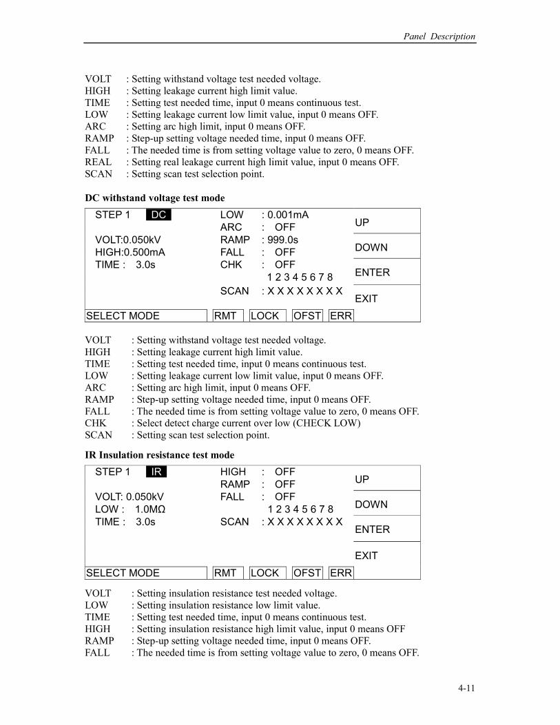
DC withstand voltage test mode
LOW : 0.001mA STEP 1 DC
ARC : OFF UP
VOLT:0.050kV RAMP : 999.0s
HIGH:0.500mA FALL : OFF DOWN
TIME : 3.0s CHK : OFF
1 2 3 4 5 6 7 8 ENTER
SCAN : X X X X X X X X
SELECT MODE RMT LOCK OFST ERR
EXIT
VOLT : Setting withstand voltage test needed voltage.
HIGH : Setting leakage current high limit value.
TIME : Setting test needed time, input 0 means continuous test.
LOW : Setting leakage current low limit value, input 0 means OFF.
ARC : Setting arc high limit, input 0 means OFF.
RAMP : Step-up setting voltage needed time, input 0 means OFF.
FALL : The needed time is from setting voltage value to zero, 0 means OFF.
CHK : Select detect charge current over low (CHECK LOW)
SCAN : Setting scan test selection point.
IR Insulation resistance test mode
HIGH : OFF STEP 1 IR
RAMP : OFF UP
VOLT: 0.050kV FALL : OFF
LOW : 1.0MΩ 1 2 3 4 5 6 7 8 DOWN
TIME : 3.0s SCAN : X X X X X X X X
ENTER
SELECT MODE RMT LOCK OFST ERR
EXIT
VOLT : Setting insulation resistance test needed voltage.
LOW : Setting insulation resistance low limit value.
TIME : Setting test needed time, input 0 means continuous test.
HIGH : Setting insulation resistance high limit value, input 0 means OFF
RAMP : Step-up setting voltage needed time, input 0 means OFF.
FALL : The needed time is from setting voltage value to zero, 0 means OFF.
HIPOT Tester 19051/19052/19053/19054 User’s Manual
4-12
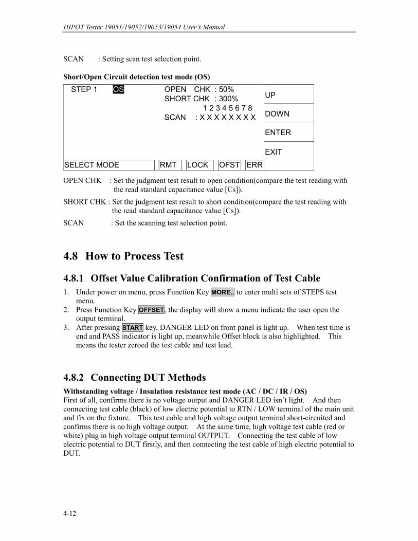
SCAN : Setting scan test selection point.
Short/Open Circuit detection test mode (OS)
OPEN CHK : 50% STEP 1 OS
SHORT CHK : 300% UP
1 2 3 4 5 6 7 8
SCAN : X X X X X X X X DOWN
ENTER
SELECT MODE RMT LOCK OFST ERR
EXIT
OPEN CHK : Set the judgment test result to open condition(compare the test reading with
the read standard capacitance value [Cs]).
SHORT CHK : Set the judgment test result to short condition(compare the test reading with
the read standard capacitance value [Cs]).
SCAN : Set the scanning test selection point.
4.8 How to Process Test
4.8.1 Offset Value Calibration Confirmation of Test Cable
1. Under power on menu, press Function Key MORE.. to enter multi sets of STEPS test
menu.
2. Press Function Key OFFSET, the display will show a menu indicate the user open the
output terminal.
3. After pressing START key, DANGER LED on front panel is light up. When test time is
end and PASS indicator is light up, meanwhile Offset block is also highlighted. This
means the tester zeroed the test cable and test lead.
4.8.2 Connecting DUT Methods
Withstanding voltage / Insulation resistance test mode (AC / DC / IR / OS)
First of all, confirms there is no voltage output and DANGER LED isn’t light. And then
connecting test cable (black) of low electric potential to RTN / LOW terminal of the main unit
and fix on the fixture. This test cable and high voltage output terminal short-circuited and
confirms there is no high voltage output. At the same time, high voltage test cable (red or
white) plug in high voltage output terminal OUTPUT. Connecting the test cable of low
electric potential to DUT firstly, and then connecting the test cable of high electric potential to
DUT.

Panel Description
4-13
4.8.3 Test Procedure (AC / DC / IR / OS)
4.8.3.1 AC / DC / IR Test Procedure
1. Connection is completed correctly by connecting DUT device method.
2. Under power on menu (as the following figure):
STEP 1/2 AC LOW : OFF
ARC : OFF PROGRAM
0.050kV RAMP : OFF
FALL : OFF PRESET
0.500mA REAL : OFF
1 2 3 4 5 6 7 8 MENU
3.0s SCAN : X X X X X X X X
RMT LOCK OFST ERR MORE..
Schema:
STEP 1/2 means there are 2 test procedures in total and now executing the first test
procedure. AC means test mode. "Line 1" means setting voltage value, "Line 2"
means setting current high limit, "Line 3" means test time. The test results are shown on
the status list.
3. Please press STOP key, ready for testing, the status list show "STANDBY".
4. Press START key to start test.
When press this key, start voltage output. At the same time, DANGER LED will be
lighted, the status list shows "UNDER TEST". Warning: Now test status is with output
voltage. "Line 1" will show output voltage output value; "Line 2" will show current
reading. "Line 3" the timer is counting down simultaneously.
5. GOOD judgment
When all of test statuses have been tested and the result shows PASS, then the main unit
is judged as GOOD and cut off output. The rear panel outputs PASS signal, the buzzer
functions simultaneously.
6. No good judgment
If the measurement value is abnormal, the main unit is judged as FAIL and stop to output
immediately. The rear panel outputs FAIL signal, the buzzer functions simultaneously.
Keep on function until STOP key of the main unit be pressed. The test result will show
no good status.
Test result Meaning
HI Measurement current / Resistance value over high limit
LO Measurement current / Resistance value over low limit
ARC Current arc over high limit
CHECK LOW Charging current over low
ADV OVER Voltage / current reading over hardware valid digit.
ADI OVER Current / resistance reading over hardware valid digit.
GR CONT. Grounding on test no good
GFI TRIP Ground fail interrupt
AC REAL HI Real current measurement value over high limit
Under any circumstances only need to press STOP key if you want to stop the test output.
Line 1
Line 2
Line 3
HIPOT Tester 19051/19052/19053/19054 User’s Manual
4-14
4.8.3.2 OS Test Procedure
1. Connection is completed correctly by connecting DUT device method under standby
menu.
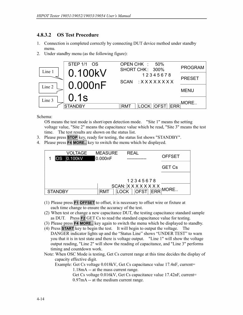
2. Under standby menu (as the following figure):
STEP 1/1 OS OPEN CHK : 50%
SHORT CHK : 300% PROGRAM
0.100kV 1 2 3 4 5 6 7 8
SCAN : X X X X X X X X PRESET
0.000nF
MENU
0.1s
STANDBY RMT LOCK OFST ERR MORE..
Schema:
OS means the test mode is short/open detection mode. "Site 1" means the setting
voltage value, "Site 2" means the capacitance value which be read, "Site 3" means the test
time. The test results are shown on the status list.
3. Please press STOP key, ready for testing, the status list shows "STANDBY".
4. Please press F4 MORE.. key to switch the menu which be displayed.
VOLTAGE MEASURE REAL
1 OS 0.100kV 0.000nF ------------- OFFSET
GET Cs
1 2 3 4 5 6 7 8
SCAN: X X X X X X X X
STANDBY RMT LOCK OFST ERR MORE..
(1) Please press F1 OFFSET to offset, it is necessary to offset wire or fixture at
each time change to ensure the accuracy of the test.
(2) When test or change a new capacitance DUT, the testing capacitance standard sample
as DUT. Press F2 GET Cs to read the standard capacitance value for testing.
(3) Please press F4 MORE.. key again to switch the menu which be displayed to standby.
(4) Press START key to begin the test. It will begin to output the voltage. The
DANGER indicator lights up and the “Status Line” shows “UNDER TEST” to warn
you that it is in test state and there is voltage output. "Line 1" will show the voltage
output reading, "Line 2" will show the reading of capacitance, and "Line 3" performs
timing and countdown work.
Note: When OSC Mode is testing, Get Cs current range at this time decides the display of
capacity effective digit.
Example: Get Cs voltage 0.018kV, Get Cs capacitance value 17.4nF, current=
1.18mA -- at the mass current range.
Get Cs voltage 0.016kV, Get Cs capacitance value 17.42nF, current=
0.97mA -- at the medium current range.
Line 1
Line 2
Line 3
Panel Description
4-15
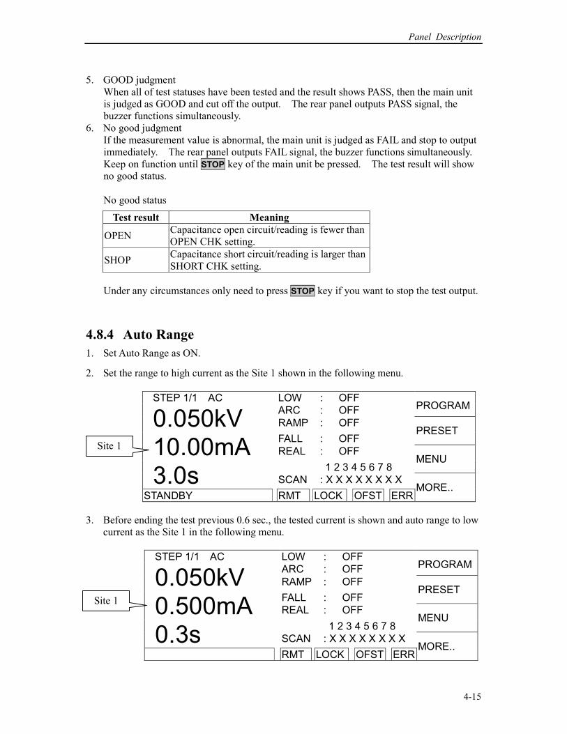
5. GOOD judgment
When all of test statuses have been tested and the result shows PASS, then the main unit
is judged as GOOD and cut off the output. The rear panel outputs PASS signal, the
buzzer functions simultaneously.
6. No good judgment
If the measurement value is abnormal, the main unit is judged as FAIL and stop to output
immediately. The rear panel outputs FAIL signal, the buzzer functions simultaneously.
Keep on function until STOP key of the main unit be pressed. The test result will show
no good status.
No good status
Test result Meaning
OPEN Capacitance open circuit/reading is fewer than
OPEN CHK setting.
SHOP Capacitance short circuit/reading is larger than
SHORT CHK setting.
Under any circumstances only need to press STOP key if you want to stop the test output.
4.8.4 Auto Range
1. Set Auto Range as ON.
2. Set the range to high current as the Site 1 shown in the following menu.
STEP 1/1 AC LOW : OFF
ARC : OFF PROGRAM
0.050kV RAMP : OFF
FALL : OFF PRESET
10.00mA REAL : OFF
1 2 3 4 5 6 7 8 MENU
3.0s SCAN : X X X X X X X X
STANDBY RMT LOCK OFST ERR MORE..
3. Before ending the test previous 0.6 sec., the tested current is shown and auto range to low
current as the Site 1 in the following menu.
STEP 1/1 AC LOW : OFF
ARC : OFF PROGRAM
0.050kV RAMP : OFF
FALL : OFF PRESET
0.500mA REAL : OFF
1 2 3 4 5 6 7 8 MENU
0.3s SCAN : X X X X X X X X
RMT LOCK OFST ERR MORE..
Site 1
Site 1

HIPOT Tester 19051/19052/19053/19054 User’s Manual
4-16
4.9 KEY LOCK Function
4.9.1 KEY LOCK Setting Method
1. Under power on menu, if "LOCK" text block isn’t highlighted then can set KEY LOCK
function.
2. Press Function Key MENU then show the following menu:
1. MEMORY UP
2. SYSTEM
3. OPTION DOWN
4. CALIBRATION
5. KEY LOCK SELECT
SELECT FUNC. RMT LOCK OFST ERR EXIT
3. Move the highlighted to "KEY LOCK " by using Function Keys UP, DOWN. Press
Function Key SELECT to enter KEY LOCK setting menu.
4. Using Function Keys A, B to input PASSWORD (please input AAAA, when
PASSWORD is not set).
5. Press ENTER key will show selection window, "LOCK" text block will show highlighted.
The user can use Function Keys YES, NO to select whether LOCK MEMORY RECALL
function together or not.
6. Press Function Keys EXIT to complete KEY LOCK function.
4.9.2 KEY LOCK Release Method
1. Under power on menu, if "LOCK" text block is highlighted then can release KEY LOCK
function.
2. Press Function Key MENU then show the following menu:
1. MEMORY UP
2. SYSTEM
3. OPTION DOWN
4. CALIBRATION
5. KEY LOCK SELECT
SELECT FUNC. RMT LOCK OFST ERR EXIT
3. Move the highlighted to "KEY LOCK" by using Function Keys UP, DOWN. Press
Function Key SELECT to enter KEY LOCK release menu.
4. Using Function Keys A, B to input PASSWORD (please input AAAA, when
PASSWORD is not set).
5. Press Function Key ENTER key, "LOCK" text block will release the highlighted. It
means KEY LOCK function is released.

Panel Description
4-17
4.10 Setting User Password
1. Under power on menu, press Function Key MENU then show the following menu:
1. MEMORY UP
2. SYSTEM
3. OPTION DOWN
4. CALIBRATION
5. KEY LOCK SELECT
SELECT FUNC. RMT LOCK OFST ERR EXIT
2. Move the highlighted to "CHANGE PASSWORD" by using Function Keys UP, DOWN.
Press Function Key ENTER to enter password input menu.
3. Using Function Keys A, B to input PASSWORD (please input AAAA, when
PASSWORD is not set). Press ENTER key will show "ENTER NEW PASSWORD" window.
4. Using Function Keys A, B to input NEW PASSWORD (not over ten characters), press
ENTER key will shows “ENTER CONFIRM PASSWORD” window.
5. Using Function Keys A, B to input CONFIRM PASSWORD (the same as NEW
PASSWORD), press ENTER key. At the same time, the setting has been done and can
press EXIT to exit.
4.11 Remote Control
This tester has REMOTE socket of remote switch on rear panel. When you want to control
this tester by external signal, plug the control cable in the socket. Please don’t touch high
voltage terminal or it may cause dangerous. Remote control by high voltage test bar usually.
Can use other control circuit instead of high voltage bar. Please notice that is switch of
controlling high voltage output. Be careful that the control cables don’t close high voltage
terminal and test cables to avoid dangerous.
1. If want to control START single and STOP signal can refer to figure 4-5. As this figure
described method connect to REMOTE position on front panel.

HIPOT Tester 19051/19052/19053/19054 User’s Manual
4-18
Figure 4-5 Figure 4-6
2. As figure 4-6, the main unit is under STOP status. NC point is connecting to STOP and
NO point connecting to START.
3. Some logical components such as transistor, FET, coupler. Also can be used to connect
as control circuit as figure 4-7. The connecting signal and circuit as figure 4-7. Only
the circuit includes the following statuses, it can control the main unit.
(1) The signal of LOW flows current is 2mA or less.
(2) The action time of inputting signal should over 20mS.
Figure 4-7
4. The relay switch control as figure 4-5 and photo-coupler control as figure 4-7 are
controlled by component contact. It is effective to avoid error operation system cause by
interference. Although the main unit has a lot of preventions, it is necessary to be
careful that interferences result from setting measurement system.
5. Pin diagram of REMOTE CONTROL as figure 4-8. When you want to control by
external, please remember this pin diagram.
Panel Description
4-19
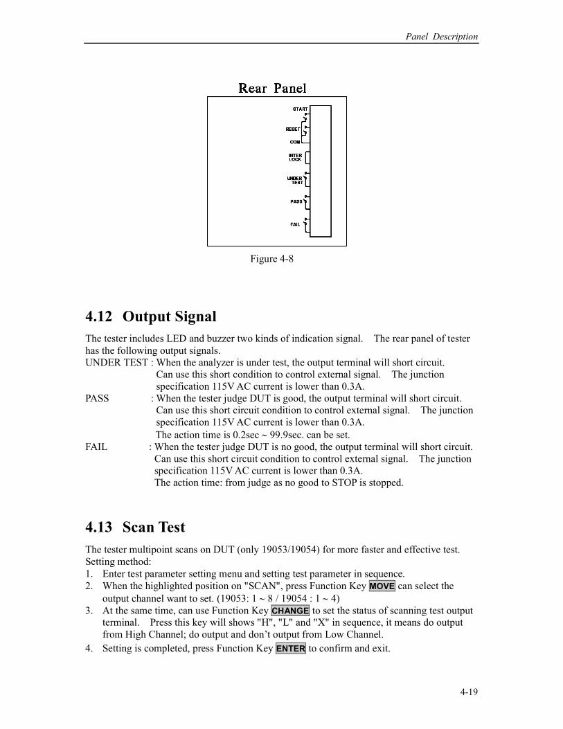
Figure 4-8
4.12 Output Signal
The tester includes LED and buzzer two kinds of indication signal. The rear panel of tester
has the following output signals.
UNDER TEST : When the analyzer is under test, the output terminal will short circuit.
Can use this short condition to control external signal. The junction
specification 115V AC current is lower than 0.3A.
PASS : When the tester judge DUT is good, the output terminal will short circuit.
Can use this short circuit condition to control external signal. The junction
specification 115V AC current is lower than 0.3A.
The action time is 0.2sec ∼ 99.9sec. can be set.
FAIL : When the tester judge DUT is no good, the output terminal will short circuit.
Can use this short circuit condition to control external signal. The junction
specification 115V AC current is lower than 0.3A.
The action time: from judge as no good to STOP is stopped.
4.13 Scan Test
The tester multipoint scans on DUT (only 19053/19054) for more faster and effective test.
Setting method:
1. Enter test parameter setting menu and setting test parameter in sequence.
2. When the highlighted position on "SCAN", press Function Key MOVE can select the
output channel want to set. (19053: 1 ∼ 8 / 19054 : 1 ∼ 4)
3. At the same time, can use Function Key CHANGE to set the status of scanning test output
terminal. Press this key will shows "H", "L" and "X" in sequence, it means do output
from High Channel; do output and don’t output from Low Channel.
4. Setting is completed, press Function Key ENTER to confirm and exit.

GPIB Operation Description (Option)
5-1
5. GPIB Operation Description (Option)
5.1 Guide
The user can use computer by GPIB (IEEE 488-1978) interface to remote control and data
transfer.
5.2 Interface Specification
5.2.1 Adaptable Standard
IEEE488-1978 standard
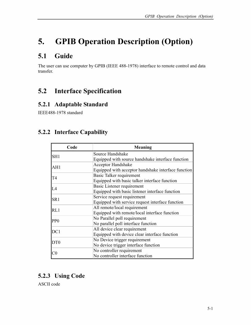
5.2.2 Interface Capability
Code Meaning
SH1 Source Handshake
Equipped with source handshake interface function
AH1 Acceptor Handshake
Equipped with acceptor handshake interface function
T4 Basic Talker requirement
Equipped with basic talker interface function
L4 Basic Listener requirement
Equipped with basic listener interface function
SR1 Service request requirement
Equipped with service request interface function
RL1 All remote/local requirement
Equipped with remote/local interface function
PP0 No Parallel poll requirement
No parallel poll interface function
DC1 All device clear requirement
Equipped with device clear interface function
DT0 No Device trigger requirement
No device trigger interface function
C0 No controller requirement
No controller interface function
5.2.3 Using Code
ASCII code

HIPOT Tester 19051/19052/19053/19054 User’s Manual
5-2
5.3 GPIB Related Panel Descriptions
5.3.1 Address Setting
1. Under power on menu, press Function Key MENU as the following:
1. MEMORY UP
2. SYSTEM
3. OPTION DOWN
4. CALIBRATION
5. KEY LOCK SELECT
SELECT FUNC. RMT LOCK OFST ERR EXIT
2. Move the highlight to "OPTION" by Function Key UP, DOWN. Press Function Key
SELECT to enter OPTION select setting as the following:
1. RS232 UP
2. GPIB
3. SCANNER DOWN
SELECT
RMT LOCK OFST ERR EXIT
3. Move the highlighted to "GPIB" by Function Key UP, DOWN. Press Function Key
SELECT to enter GPIB setting menu as the following:
1. GPIB ADDR. : 3 UP
DOWN
ENTER
RMT LOCK OFST ERR
EXIT
4. Then select GPIB Address by Function Key UP, DOWN.
5. The setting is completed, press Function Key EXIT to exit.
5.3.2 Remote / Local
1. The signal block Remote is highlighted, it means the analyzer is on Remote status.
2. On Remote status can use LOCAL key on panel switch the analyzer to Local status.
3. On Remote status, all of panel keys are malfunction except for Function Key LOCAL

GPIB Operation Description (Option)
5-3
(switch to Local) MENU, MORE.. and STOP (reset instrument) keys.
4. By using LLO [Local lockout] command of GPIB makes LOCAL key is malfunction.
5.4 Interface Message
The analyzer is capable of responding to the following messages
Signal Meaning Response
GTL Go To Local Can switch the analyzer to Local status
SDC Selected Device Clear Restart the analyzer
LLO Local Lockout From LOCAL key switch to Local status is forbidden
IFC Interface Clear Reset GPIB interface
5.5 GPIB Control / Setting Command Descriptions
The analyzer GPIB function composed command string is inputted by ASCII code to attain
functions of remote control and setting. The length of the command string is limited in 1024
characters (include end code) [Command + Parameter] compose a command. Two
commands can be connected by semicolon and end by ending code. The end code are the
following types, the analyzer can distinguish it by self.
End code
LF
CR+LF
EOI
LF+EOI
CR+LF+EOI
Status response command
CLS
ESE <enable value>
ESE?
ESR?
SRE <enable value>
SRE?
STB?
PSC 0|1
PSC?
HIPOT Tester 19051/19052/19053/19054 User’s Manual
5-4
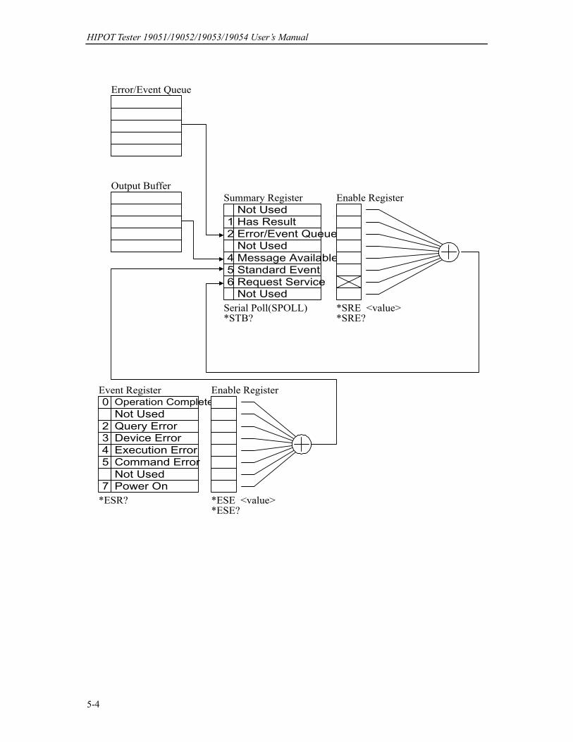
Error/Event Queue
Output Buffer
Summary Register
654
21
Not Used
Error/Event Queue
Not Used
Has Result
Request ServiceStandard Event
Not UsedMessage Available
0
2
7
543
Operation Complete
Power OnNot UsedCommand ErrorExecution ErrorDevice ErrorQuery ErrorNot Used
Enable Register
Serial Poll(SPOLL)*STB?
*SRE <value>*SRE?
*ESE <value>*ESE?
*ESR?
Event Register Enable Register
GPIB Operation Description (Option)
5-5
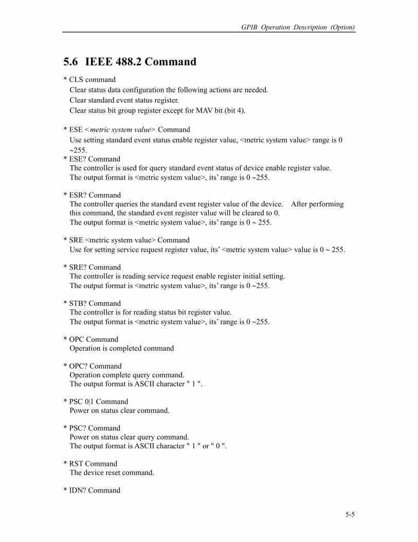
5.6 IEEE 488.2 Command
* CLS command
Clear status data configuration the following actions are needed.
Clear standard event status register.
Clear status bit group register except for MAV bit (bit 4).
* ESE <metric system value> Command
Use setting standard event status enable register value, <metric system value> range is 0
∼255.
* ESE? Command
The controller is used for query standard event status of device enable register value.
The output format is <metric system value>, its’ range is 0 ∼255.
* ESR? Command
The controller queries the standard event register value of the device. After performing
this command, the standard event register value will be cleared to 0.
The output format is <metric system value>, its’ range is 0 ∼ 255.
* SRE <metric system value> Command
Use for setting service request register value, its’ <metric system value> value is 0 ∼ 255.
* SRE? Command
The controller is reading service request enable register initial setting.
The output format is <metric system value>, its’ range is 0 ∼255.
* STB? Command
The controller is for reading status bit register value.
The output format is <metric system value>, its’ range is 0 ∼255.
* OPC Command
Operation is completed command
* OPC? Command
Operation complete query command.
The output format is ASCII character " 1 ".
* PSC 0|1 Command
Power on status clear command.
* PSC? Command
Power on status clear query command.
The output format is ASCII character " 1 " or " 0 ".
* RST Command
The device reset command.
* IDN? Command
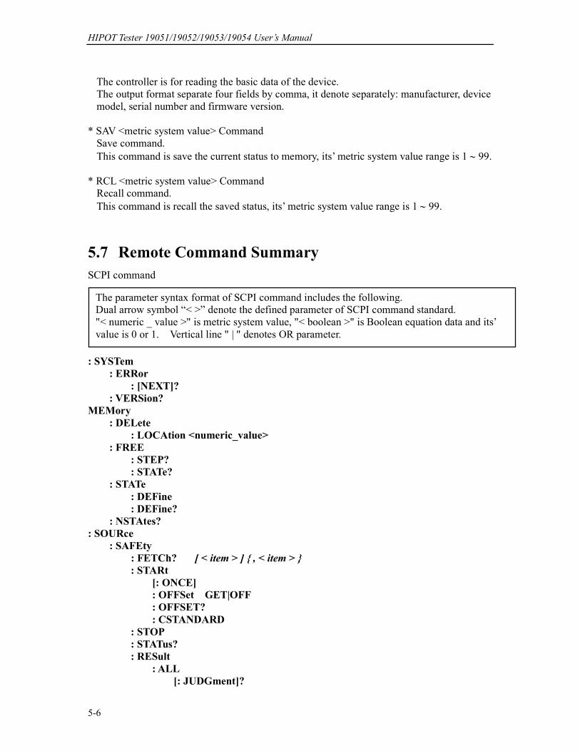
HIPOT Tester 19051/19052/19053/19054 User’s Manual
5-6
The controller is for reading the basic data of the device.
The output format separate four fields by comma, it denote separately: manufacturer, device
model, serial number and firmware version.
* SAV <metric system value> Command
Save command.
This command is save the current status to memory, its’ metric system value range is 1 ∼ 99.
* RCL <metric system value> Command
Recall command.
This command is recall the saved status, its’ metric system value range is 1 ∼ 99.
5.7 Remote Command Summary
SCPI command
: SYSTem
: ERRor
: [NEXT]?
: VERSion?
MEMory
: DELete
: LOCAtion <numeric_value>
: FREE
: STEP?
: STATe?
: STATe
: DEFine
: DEFine?
: NSTAtes?
: SOURce
: SAFEty
: FETCh? [ < item > ] , < item >
: STARt
[: ONCE]
: OFFSet GET|OFF
: OFFSET?
: CSTANDARD
: STOP
: STATus?
: RESult
: ALL
[: JUDGment]?
The parameter syntax format of SCPI command includes the following.
Dual arrow symbol “< >” denote the defined parameter of SCPI command standard.
"< numeric _ value >" is metric system value, "< boolean >" is Boolean equation data and its’
value is 0 or 1. Vertical line " | " denotes OR parameter.
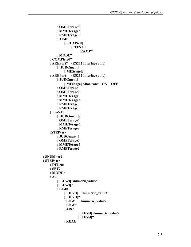
GPIB Operation Description (Option)
5-7
: OMETerage?
: MMETerage?
: RMETerage?
: TIME
[: ELAPsed]
[: TEST]?
: RAMP?
: MODE?
: COMPleted?
: AREPort? (RS232 Interface only)
[: JUDGment]
[:MESsage]?
: AREPort (RS232 Interface only)
[:JUDGment]
[:MESsage] <Boolean> ON OFF : OMETerage
: OMETerage?
: MMETerage
: MMETerage?
: RMETerage
: RMETerage?
[: LAST]
[: JUDGment]?
: OMETerage?
: MMETerage?
: RMETerage?
:STEP<n>
: JUDGment]?
: OMETerage?
: MMETerage?
: RMETerage?
: SNUMber?
: STEP<n>
: DELete
: SET?
: MODE?
: AC
[: LEVel] <numeric value>
[: LEVel]?
: LIMit
[: HIGH] <numeric_value>
[: HIGH]?
: LOW <numeric_value>
: LOW?
: ARC
[: LEVel] <numeric_value>
[: LEVel]?
: REAL
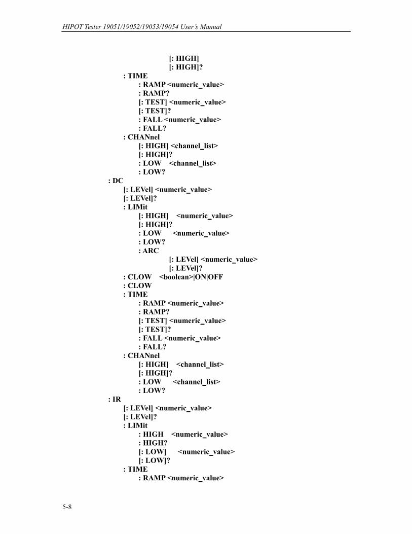
HIPOT Tester 19051/19052/19053/19054 User’s Manual
5-8
[: HIGH]
[: HIGH]?
: TIME
: RAMP <numeric_value>
: RAMP?
[: TEST] <numeric_value>
[: TEST]?
: FALL <numeric_value>
: FALL?
: CHANnel
[: HIGH] <channel_list>
[: HIGH]?
: LOW <channel_list>
: LOW?
: DC
[: LEVel] <numeric_value>
[: LEVel]?
: LIMit
[: HIGH] <numeric_value>
[: HIGH]?
: LOW <numeric_value>
: LOW?
: ARC
[: LEVel] <numeric_value>
[: LEVel]?
: CLOW <boolean>|ON|OFF
: CLOW
: TIME
: RAMP <numeric_value>
: RAMP?
[: TEST] <numeric_value>
[: TEST]?
: FALL <numeric_value>
: FALL?
: CHANnel
[: HIGH] <channel_list>
[: HIGH]?
: LOW <channel_list>
: LOW?
: IR
[: LEVel] <numeric_value>
[: LEVel]?
: LIMit
: HIGH <numeric_value>
: HIGH?
[: LOW] <numeric_value>
[: LOW]?
: TIME
: RAMP <numeric_value>

GPIB Operation Description (Option)
5-9
: RAMP?
[: TEST] <numeric_value>
[: TEST]?
: FALL <numeric_value>
: FALL?
: CHANnel
[: HIGH] <channel_list>
[: HIGH]?
: LOW <channel_list>
: LOW?
: OSC
: LIMit
: OPEN <numeric_value>
: OPEN?
: SHORT <numeric_value>
: SHORT?
: CHANnel
[: HIGH] <channel_list>
[: HIGH]?
: LOW <channel_list>
: LOW?
: PRESet
: TIME
: PASS <numeric_value>
: PASS?
: STEP <numeric_value>|KEY
: STEP?
: JUDGment <numeric_value>
: JUDGment?
: AC
: FREQuncy <numeric_value>
: FREQuery?
: WRANge
[: AUTO] <boolean>|ON|OFF
[: AUTO]?
: AGC
[: SOFTware] <boolean>|ON|OFF
[: SOFTware]?
: GFI
[: SWITCH] <boolean>|ON|OFF
[: SWITCH]?
: FCONtinuity <boolean> |ON|OFF
: FCONtinuity
: GR
: CONTinue <boolean>|ON|OFF
: CONTinue?
: FCONtinuity <boolean> |ON|OFF
: FCONtinuity
: NUMber
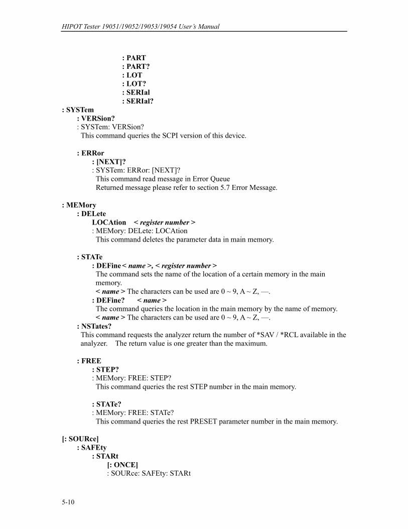
HIPOT Tester 19051/19052/19053/19054 User’s Manual
5-10
: PART
: PART?
: LOT
: LOT?
: SERIal
: SERIal?
: SYSTem
: VERSion? : SYSTem: VERSion?
This command queries the SCPI version of this device.
: ERRor
: [NEXT]? : SYSTem: ERRor: [NEXT]?
This command read message in Error Queue
Returned message please refer to section 5.7 Error Message.
: MEMory
: DELete
LOCAtion < register number > : MEMory: DELete: LOCAtion
This command deletes the parameter data in main memory.
: STATe
: DEFine < name >, < register number > The command sets the name of the location of a certain memory in the main
memory.
< name > The characters can be used are 0 ~ 9, A ~ Z, —.
: DEFine? < name >
The command queries the location in the main memory by the name of memory.
< name > The characters can be used are 0 ~ 9, A ~ Z, —.
: NSTates?
This command requests the analyzer return the number of *SAV / *RCL available in the
analyzer. The return value is one greater than the maximum.
: FREE
: STEP? : MEMory: FREE: STEP?
This command queries the rest STEP number in the main memory.
: STATe? : MEMory: FREE: STATe?
This command queries the rest PRESET parameter number in the main memory.
[: SOURce]
: SAFEty
: STARt
[: ONCE] : SOURce: SAFEty: STARt
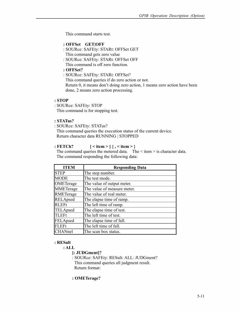
GPIB Operation Description (Option)
5-11
This command starts test.
: OFFSet GET|OFF : SOURce: SAFEty: STARt: OFFSet GET
This command gets zero value
: SOURce: SAFEty: STARt: OFFSet OFF
This command is off zero function.
: OFFSet? : SOURce: SAFEty: STARt: OFFSet?
This command queries if do zero action or not.
Return 0, it means don’t doing zero action, 1 means zero action have been
done, 2 means zero action processing.
: STOP
: SOURce: SAFEty: STOP
This command is for stopping test.
: STATus? : SOURce: SAFEty: STATus?
This command queries the execution status of the current device.
Return character data RUNNING | STOPPED
: FETCh? [ < item > ] , < item > The command queries the metered data. The < item > is character data.
The command responding the following data:
ITEM Responding Data
STEP The step number.
MODE The test mode.
OMETerage The value of output meter.
MMETerage The value of measure meter.
RMETerage The value of real meter.
RELApsed The elapse time of ramp.
RLEFt The left time of ramp.
TELApsed The elapse time of test.
TLEFt The left time of test.
FELApsed The elapse time of fall.
FLEFt The left time of fall.
CHANnel The scan box status.
: RESult
: ALL
[: JUDGment]? : SOURce: SAFEty: RESult: ALL: JUDGment?
This command queries all judgment result.
Return format:
: OMETerage?
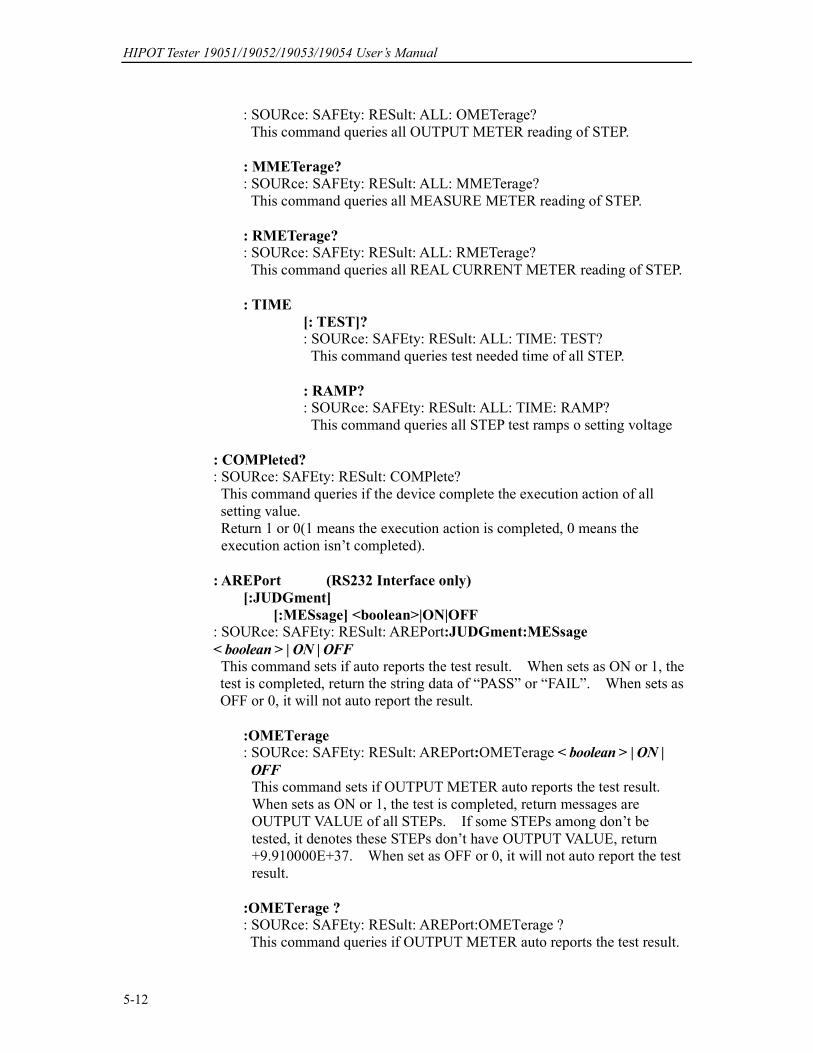
HIPOT Tester 19051/19052/19053/19054 User’s Manual
5-12
: SOURce: SAFEty: RESult: ALL: OMETerage?
This command queries all OUTPUT METER reading of STEP.
: MMETerage?
: SOURce: SAFEty: RESult: ALL: MMETerage?
This command queries all MEASURE METER reading of STEP.
: RMETerage? : SOURce: SAFEty: RESult: ALL: RMETerage?
This command queries all REAL CURRENT METER reading of STEP.
: TIME
[: TEST]? : SOURce: SAFEty: RESult: ALL: TIME: TEST?
This command queries test needed time of all STEP.
: RAMP? : SOURce: SAFEty: RESult: ALL: TIME: RAMP?
This command queries all STEP test ramps o setting voltage
: COMPleted? : SOURce: SAFEty: RESult: COMPlete?
This command queries if the device complete the execution action of all
setting value.
Return 1 or 0(1 means the execution action is completed, 0 means the
execution action isn’t completed).
: AREPort (RS232 Interface only)
[:JUDGment]
[:MESsage] <boolean>|ON|OFF : SOURce: SAFEty: RESult: AREPort:JUDGment:MESsage
< boolean > | ON | OFF
This command sets if auto reports the test result. When sets as ON or 1, the
test is completed, return the string data of “PASS” or “FAIL”. When sets as
OFF or 0, it will not auto report the result.
:OMETerage : SOURce: SAFEty: RESult: AREPort:OMETerage < boolean > | ON |
OFF This command sets if OUTPUT METER auto reports the test result.
When sets as ON or 1, the test is completed, return messages are
OUTPUT VALUE of all STEPs. If some STEPs among don’t be
tested, it denotes these STEPs don’t have OUTPUT VALUE, return
+9.910000E+37. When set as OFF or 0, it will not auto report the test
result.
:OMETerage ? : SOURce: SAFEty: RESult: AREPort:OMETerage ?
This command queries if OUTPUT METER auto reports the test result.

GPIB Operation Description (Option)
5-13
Return 1 or 0 (1 means OUTPUT METER will auto reports the test
result, 0 means OUTPUT METER will not auto reports the test result).
:MMETerage
: SOURce: SAFEty: RESult: AREPort:MMETerage < boolean > | ON |
OFF
This command sets if MEASURE METER auto reports the test result.
When sets as OFF or 1, the test is completed, return messages are
MEASURE VALUE of all STEPs. If some STEPs among don’t be
tested, it denotes these STEPs don’t have MEASURE VALUE, return
+9.910000E+37. When set as OFF or 0, it will not auto report the test
result.
: MMETerage ? : SOURce: SAFEty: RESult: AREPort: MMETerage ?
This command queries if MEASURE METER auto reports the test result.
Return 1 or 0 (1 means MEASURE METER will auto reports the test
result, 0 means MEASURE METER will not auto reports the test result).
:RMETerage : SOURce: SAFEty: RESult: AREPort:RMETerage < boolean > | ON |
OFF This command sets if REAL CURRENT METER auto reports the test
result. When sets as OFF or 1, the test is completed, return messages
are REAL CURRENT VALUE of all STEPs. If some STEPs among
don’t be tested, it denotes these STEPs don’t have REAL CURRENT
VALUE, return +9.910000E+37. When set as OFF or 0, it will not
auto report the test result
:RMETerage ? : SOURce: SAFEty: RESult: AREPort:RMETerage ?
This command queries if REAL CURRENT METER auto reports the
test result. Return 1 or 0 (1 means REAL CURRENT METER will
auto reports the test result, 0 means REAL CURRENT METER will not
auto reports the test result).
[: LAST]?
[: JUDGment]? : SOURce: SAFEty: RESult: LAST: JUDGment?
This command queries the judgment result code of the last STEP.
: OMETerage? : SOURce: SAFEty: RESult: LAST: OMETerage?
This command queries OUTPUT METER reading of the last STEP.
: MMETerage? : SOURce: SAFEty: RESult: LAST: MMETerage?
This command queries MEASURE METER reading of the last STEP.
: RMETerage? : SOURce: SAFEty: RESult: LAST: RMETerage?
This command queries REAL CURRENT METER reading of the last
STEP.

HIPOT Tester 19051/19052/19053/19054 User’s Manual
5-14
: STEP<n>
: JUDGment? : SOURce: SAFEty: RESult: STEP: JUDGment?
This command queries the judgment result code of selected STEP.
: OMETerage? : SOURce: SAFEty: RESult: STEP: OMETerage?
This command queries OUTPUT METER reading of selected STEP.
: MMETerage? : SOURce: SAFEty: RESult: STEP: MMETerage?
This command queries MEASURE METER reading of selected STEP.
: RMETerage? : SOURce: SAFEty: RESult: STEP: RMETerage?
This command queries REAL CURRENT METER reading of selected
STEP.
Common judgment result code list
Judgment Result Code (HEX) Code (metric system)
PASS 0×74 116
USER STOP 0×71 113
CAN NOT TEST 0×72 114
TESTING 0×73 115
STOP 0×70 112
Judgment result no good code list
AC MODE DC MODE IR MODE
Hex Dec Hex Dec Hex Dec
HI 11 17 21 33 31 49
LO 12 18 22 34 32 50
ARC 13 19 23 35 33 ----
IO 14 20 24 36 34 52
CHECK LOW ---- ---- 25 37 ---- ----
ADV OVER 16 22 26 38 36 54
ADI OVER 17 23 27 39 37 55
REAL HIGH 1a 26 ---- ---- ---- ----
GR CONT. 78 120 78 120 78 120
TRIPPED 79 121 79 121 79 121
IO-F 16 27 26 43 ---- ----
: SNUMber? : SOURce: SAFEty: SNUMber?
This command queries how many STEP being set in memory.
: STEP<n>
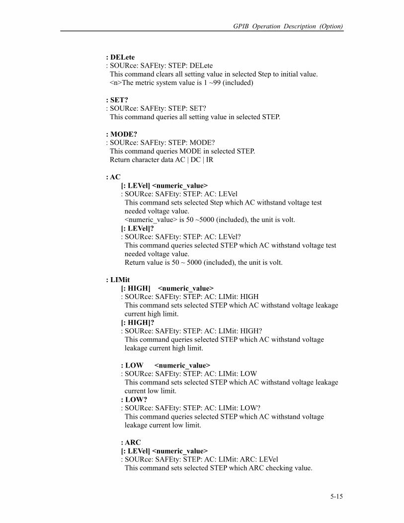
GPIB Operation Description (Option)
5-15
: DELete : SOURce: SAFEty: STEP: DELete
This command clears all setting value in selected Step to initial value.
<n>The metric system value is 1 ~99 (included)
: SET? : SOURce: SAFEty: STEP: SET?
This command queries all setting value in selected STEP.
: MODE? : SOURce: SAFEty: STEP: MODE?
This command queries MODE in selected STEP.
Return character data AC | DC | IR
: AC
[: LEVel] <numeric_value> : SOURce: SAFEty: STEP: AC: LEVel
This command sets selected Step which AC withstand voltage test
needed voltage value.
<numeric_value> is 50 ~5000 (included), the unit is volt.
[: LEVel]? : SOURce: SAFEty: STEP: AC: LEVel?
This command queries selected STEP which AC withstand voltage test
needed voltage value.
Return value is 50 ~ 5000 (included), the unit is volt.
: LIMit
[: HIGH] <numeric_value> : SOURce: SAFEty: STEP: AC: LIMit: HIGH
This command sets selected STEP which AC withstand voltage leakage
current high limit.
[: HIGH]?
: SOURce: SAFEty: STEP: AC: LIMit: HIGH?
This command queries selected STEP which AC withstand voltage
leakage current high limit.
: LOW <numeric_value> : SOURce: SAFEty: STEP: AC: LIMit: LOW
This command sets selected STEP which AC withstand voltage leakage
current low limit.
: LOW? : SOURce: SAFEty: STEP: AC: LIMit: LOW?
This command queries selected STEP which AC withstand voltage
leakage current low limit.
: ARC
[: LEVel] <numeric_value> : SOURce: SAFEty: STEP: AC: LIMit: ARC: LEVel
This command sets selected STEP which ARC checking value.

HIPOT Tester 19051/19052/19053/19054 User’s Manual
5-16
[: LEVel]? : SOURce: SAFEty: STEP: AC: LIMit: ARC: LEVel?
This command queries selected STEP which ARC checking value.
: REAL
[: HIGH] : SOURce: SAFEty: STEP: AC: LIMit: REAL: HIGH
This command sets selected STEP which AC withstand voltage real
current high limit.
[: HIGH]? : SOURce: SAFEty: STEP: AC: LIMit: REAL: HIGH?
This command queries selected STEP which AC withstand voltage real
current high limit.
: TIME
: RAMP <numeric_value> : SOURce: SAFEty: STEP: AC: TIME: RAMP
This command sets selected STEP which test ramps to setting voltage
needed time.
: RAMP? : SOURce: SAFEty: STEP: AC: TIME: RAMP?
This command queries selected STEP which test ramps to setting
voltage needed time.
[: TEST] <numeric_value> : SOURce: SAFEty: STEP: AC: TIME: TEST
This command sets selected STEP which test needed time.
[: TEST]? : SOURce: SAFEty: STEP: AC: TIME: TEST?
This command queries selected STEP which test needed time.
: FALL <numeric value> : SOURce: SAFEty: STEP: AC: TIME: FALL
This command sets selected STEP which voltage value of setting fall to
zero needed time.
: FALL? : SOURce: SAFEty: STEP: AC: TIME: FALL?
This command queries selected STEP which setup voltage value of
falling to zero the needed time.
: CHANnel
[: HIGH] <channel_list>
: SOURce: SAFEty: STEP: AC: CHANnel: HIGH
This command sets selected step the voltage output channels.
[: HIGH]? : SOURce: SAFEty: STEP: AC: CHANnel: HIGH?
This command queries selected step the voltage output channels.
: LOW <channel_list>

GPIB Operation Description (Option)
5-17
: SOURce: SAFEty: STEP: AC: CHANnel: LOW
This command sets selected step the return channels.
: LOW? : SOURce: SAFEty: STEP: AC: CHANnel: LOW?
This command queries selected step the return channels.
: DC
[: LEVel] <numeric_value> : SOURce: SAFEty: STEP: DC: LEVel
This command sets selected STEP which DC withstand voltage test
needed voltage value.
<numeric_value> is 50-6000 (included), the unit is volt.
[: LEVel]? : SOURce: SAFEty: STEP: DC: LEVel?
This command queries selected STEP which DC withstand voltage test
needed voltage value.
Return value is 50-6000(included), the unit is volt.
: LIMit
[: HIGH] <numeric_value> : SOURce: SAFEty: STEP: DC: LIMit: HIGH
This command sets selected STEP which AC withstand voltage leakage
current high limit.
[: HIGH]?
: SOURce: SAFEty: STEP: DC: LIMit: HIGH?
This command queries selected STEP which AC withstand voltage
leakage current high limit.
: LOW <numeric_value> : SOURce: SAFEty: STEP: DC: LIMit: LOW
This command sets selected STEP which AC withstand voltage leakage
current low limit.
: LOW? : SOURce: SAFEty: STEP: DC: LIMit: LOW?
This command queries selected STEP which AC withstand voltage
leakage current low limit.
: ARC
[: LEVel] <numeric_value> : SOURce: SAFEty: STEP: DC: LIMit: ARC: LEVel
This command sets selected STEP which ARC checking value.
[: LEVel]?
: SOURce: SAFEty: STEP: DC: LIMit: ARC: LEVel?
This command queries selected STEP which ARC checking value.
: CLOW <boolern>|ON|OFF : SOURce: SAFEty: STEP: DC: CLOW
This command sets selected STEP detect if charge current over low or
not.

HIPOT Tester 19051/19052/19053/19054 User’s Manual
5-18
: CLOW? : SOURce: SAFEty: STEP: DC: CLOW?
This command queries selected STEP if detect charge current over low
or not.
: TIME
: RAMP <numeric_value> : SOURce: SAFEty: STEP: DC: TIME: RAMP
This command sets selected STEP which test ramps to set voltage
needed time.
: RAMP? : SOURce: SAFEty: STEP: DC: TIME: RAMP?
This command queries selected STEP which test ramps to set
voltage needed time.
[: TEST] <numeric_value> : SOURce: SAFEty: STEP: DC: TIME: TEST
This command sets selected STEP which test needed time.
[: TEST]? : SOURce: SAFEty: STEP: DC: TIME: TEST?
This command queries selected STEP which test needed time.
: FALL <numeric value>
: SOURce: SAFEty: STEP: AC: TIME: FALL
This command sets selected STEP which voltage value of setting
fall to zero needed time.
: FALL? : SOURce: SAFEty: STEP: AC: TIME: FALL?
This command queries selected STEP which setup voltage value
falling to zero needed time.
: CHANnel
[: HIGH] <channel_list> : SOURce: SAFEty: STEP: DC: CHANnel: HIGH
This command sets selected step the voltage output channels.
[: HIGH]? : SOURce: SAFEty: STEP: DC: CHANnel: HIGH?
This command queries selected step the voltage output channels.
: LOW <channel_list> : SOURce: SAFEty: STEP: DC: CHANnel: LOW
This command sets selected step the return channels.
: LOW? : SOURce: SAFEty: STEP: DC: CHANnel: LOW?
This command queries selected step the return channels.
: IR
[: LEVel] <numeric_value>
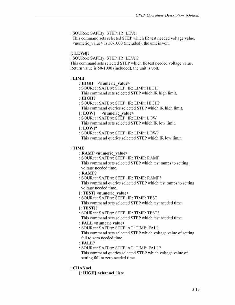
GPIB Operation Description (Option)
5-19
: SOURce: SAFEty: STEP: IR: LEVel
This command sets selected STEP which IR test needed voltage value.
<numeric_value> is 50-1000 (included), the unit is volt.
[: LEVel]?
: SOURce: SAFEty: STEP: IR: LEVel?
This command sets selected STEP which IR test needed voltage value.
Return value is 50-1000 (included), the unit is volt.
: LIMit
: HIGH <numeric_value> : SOURce: SAFEty: STEP: IR: LIMit: HIGH
This command sets selected STEP which IR high limit.
: HIGH?
: SOURce: SAFEty: STEP: IR: LIMit: HIGH?
This command queries selected STEP which IR high limit.
[: LOW] <numeric_value> : SOURce: SAFEty: STEP: IR: LIMit: LOW
This command sets selected STEP which IR low limit.
[: LOW]? : SOURce: SAFEty: STEP: IR: LIMit: LOW?
This command queries selected STEP which IR low limit.
: TIME
: RAMP <numeric_value> : SOURce: SAFEty: STEP: IR: TIME: RAMP
This command sets selected STEP which test ramps to setting
voltage needed time.
: RAMP? : SOURce: SAFEty: STEP: IR: TIME: RAMP?
This command queries selected STEP which test ramps to setting
voltage needed time.
[: TEST] <numeric_value> : SOURce: SAFEty: STEP: IR: TIME: TEST
This command sets selected STEP which test needed time.
[: TEST]? : SOURce: SAFEty: STEP: IR: TIME: TEST?
This command sets selected STEP which test needed time.
: FALL <numeric value> : SOURce: SAFEty: STEP: AC: TIME: FALL
This command sets selected STEP which voltage value of setting
fall to zero needed time.
: FALL? : SOURce: SAFEty: STEP: AC: TIME: FALL?
This command queries selected STEP which voltage value of
setting fall to zero needed time.
: CHANnel
[: HIGH] <channel_list>
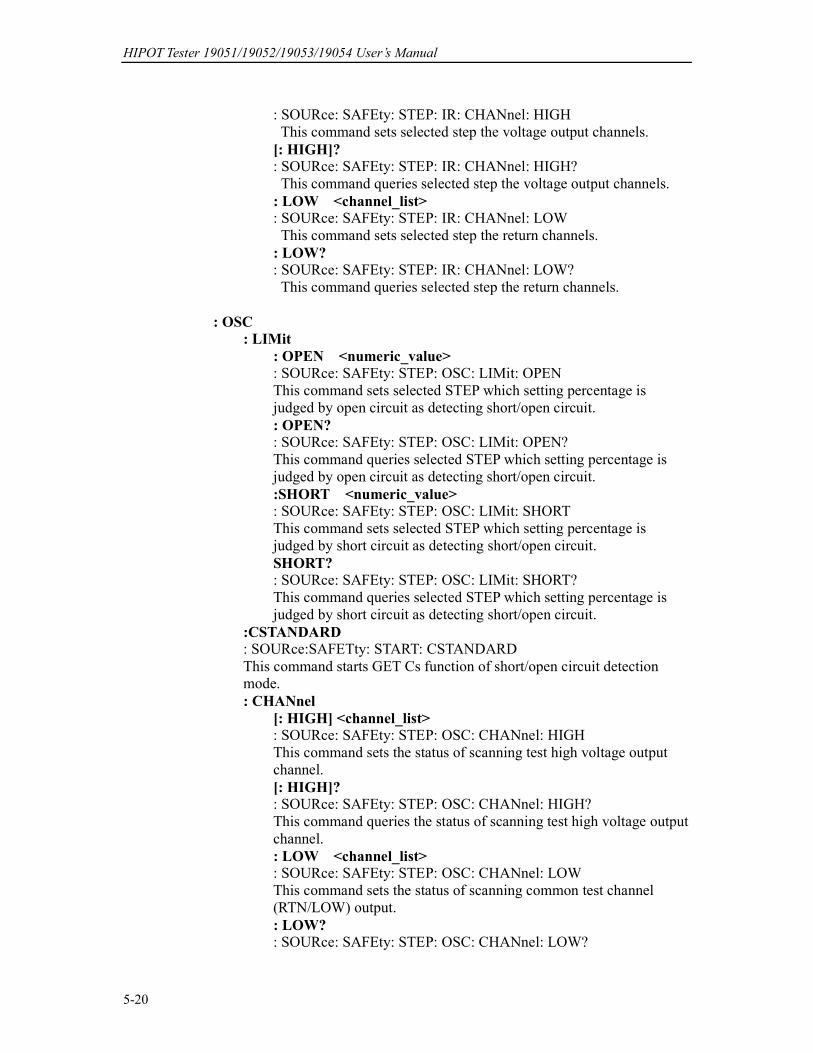
HIPOT Tester 19051/19052/19053/19054 User’s Manual
5-20
: SOURce: SAFEty: STEP: IR: CHANnel: HIGH
This command sets selected step the voltage output channels.
[: HIGH]? : SOURce: SAFEty: STEP: IR: CHANnel: HIGH?
This command queries selected step the voltage output channels.
: LOW <channel_list> : SOURce: SAFEty: STEP: IR: CHANnel: LOW
This command sets selected step the return channels.
: LOW? : SOURce: SAFEty: STEP: IR: CHANnel: LOW?
This command queries selected step the return channels.
: OSC
: LIMit
: OPEN <numeric_value>
: SOURce: SAFEty: STEP: OSC: LIMit: OPEN
This command sets selected STEP which setting percentage is
judged by open circuit as detecting short/open circuit.
: OPEN? : SOURce: SAFEty: STEP: OSC: LIMit: OPEN?
This command queries selected STEP which setting percentage is
judged by open circuit as detecting short/open circuit.
:SHORT <numeric_value> : SOURce: SAFEty: STEP: OSC: LIMit: SHORT
This command sets selected STEP which setting percentage is
judged by short circuit as detecting short/open circuit.
SHORT? : SOURce: SAFEty: STEP: OSC: LIMit: SHORT?
This command queries selected STEP which setting percentage is
judged by short circuit as detecting short/open circuit.
:CSTANDARD : SOURce:SAFETty: START: CSTANDARD
This command starts GET Cs function of short/open circuit detection
mode.
: CHANnel
[: HIGH] <channel_list> : SOURce: SAFEty: STEP: OSC: CHANnel: HIGH
This command sets the status of scanning test high voltage output
channel.
[: HIGH]? : SOURce: SAFEty: STEP: OSC: CHANnel: HIGH?
This command queries the status of scanning test high voltage output
channel.
: LOW <channel_list> : SOURce: SAFEty: STEP: OSC: CHANnel: LOW
This command sets the status of scanning common test channel
(RTN/LOW) output.
: LOW? : SOURce: SAFEty: STEP: OSC: CHANnel: LOW?
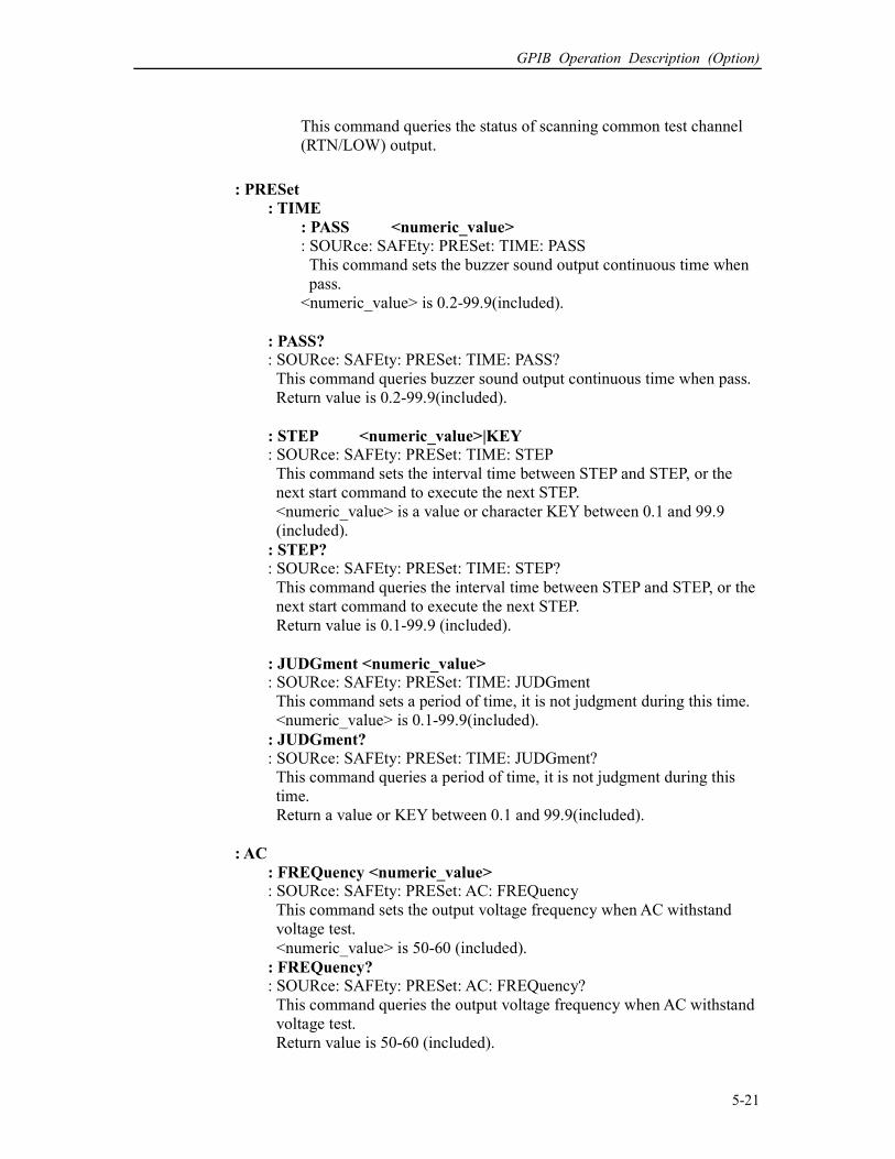
GPIB Operation Description (Option)
5-21
This command queries the status of scanning common test channel
(RTN/LOW) output.
: PRESet
: TIME
: PASS <numeric_value>
: SOURce: SAFEty: PRESet: TIME: PASS
This command sets the buzzer sound output continuous time when
pass.
<numeric_value> is 0.2-99.9(included).
: PASS? : SOURce: SAFEty: PRESet: TIME: PASS?
This command queries buzzer sound output continuous time when pass.
Return value is 0.2-99.9(included).
: STEP <numeric_value>|KEY : SOURce: SAFEty: PRESet: TIME: STEP
This command sets the interval time between STEP and STEP, or the
next start command to execute the next STEP.
<numeric_value> is a value or character KEY between 0.1 and 99.9
(included).
: STEP? : SOURce: SAFEty: PRESet: TIME: STEP?
This command queries the interval time between STEP and STEP, or the
next start command to execute the next STEP.
Return value is 0.1-99.9 (included).
: JUDGment <numeric_value> : SOURce: SAFEty: PRESet: TIME: JUDGment
This command sets a period of time, it is not judgment during this time.
<numeric_value> is 0.1-99.9(included).
: JUDGment?
: SOURce: SAFEty: PRESet: TIME: JUDGment?
This command queries a period of time, it is not judgment during this
time.
Return a value or KEY between 0.1 and 99.9(included).
: AC
: FREQuency <numeric_value> : SOURce: SAFEty: PRESet: AC: FREQuency
This command sets the output voltage frequency when AC withstand
voltage test.
<numeric_value> is 50-60 (included).
: FREQuency? : SOURce: SAFEty: PRESet: AC: FREQuency?
This command queries the output voltage frequency when AC withstand
voltage test.
Return value is 50-60 (included).

HIPOT Tester 19051/19052/19053/19054 User’s Manual
5-22
: WRANge
[: AUTO] <boolean>|ON|OFF : SOURce: SAFEty: PRESet: WRANge: AUTO
This command sets withstanding voltage auto range function is ON or
OFF.
[: AUTO]? : SOURce: SAFEty: PRESet: WRANge: AUTO?
This command queries withstanding auto range function is ON or OFF.
Return 1 or 0 (0 means withstanding voltage auto range function is OFF,
1 means withstanding voltage auto range function is ON).
: AGC
[: SOFTware] <boolean>|ON|OFF
: SOURce: SAFEty: PRESet: AGC: SOFTware
This command sets software AGC is ON or OFF.
[: SOFTware]? : SOURce: SAFEty: PRESet: AGC: SOFTware?
This command queries software AGC is ON or OFF.
Return 1 or 0 (0 means AGC is OFF, 1 means AGC is ON).
: GCONtinuity <boolean>|ON|OFF : SOURce: SAFEty: PRESet: GCONtinuity
This command sets grounding impedance test is ON or OFF.
: GCONtinuity? : SOURce: SAFEty: PRESet: GCONtinuity?
This command queries grounding impedance test is ON or OFF.
Return 1 or 0 (0 means grounding impedance is OFF, 1 means grounding
impedance is ON).
: GFI
[: SWITCH] <Boolean>|ON|OFF
: SOURce: SAFEty: PRESet: GFI: SWITCH
This command sets GFI switch is ON or OFF.
[: SWITCH]? : SOURce: SAFEty: PRESet: GFI: SWITCH?
This command queries GFI switch is ON or OFF.
Return 1 or 0 (0 means GFI is OFF, 1 means GFI is ON).
: FCONtinuity <Boolean>|ON|OFF : SOURce: SAFEty: PRESet: FCONtinuity
This command sets FAIL happened, if continuity for testing the next
step.
: SOURce: SAFEty: PRESet: FCONtinuity?
This command queries FCONtinuity is ON or OFF.
Return 1 or 0 (0 means FAIL CONT. is OFF, 1 means FAIL CONT. is
ON).
: NUMber
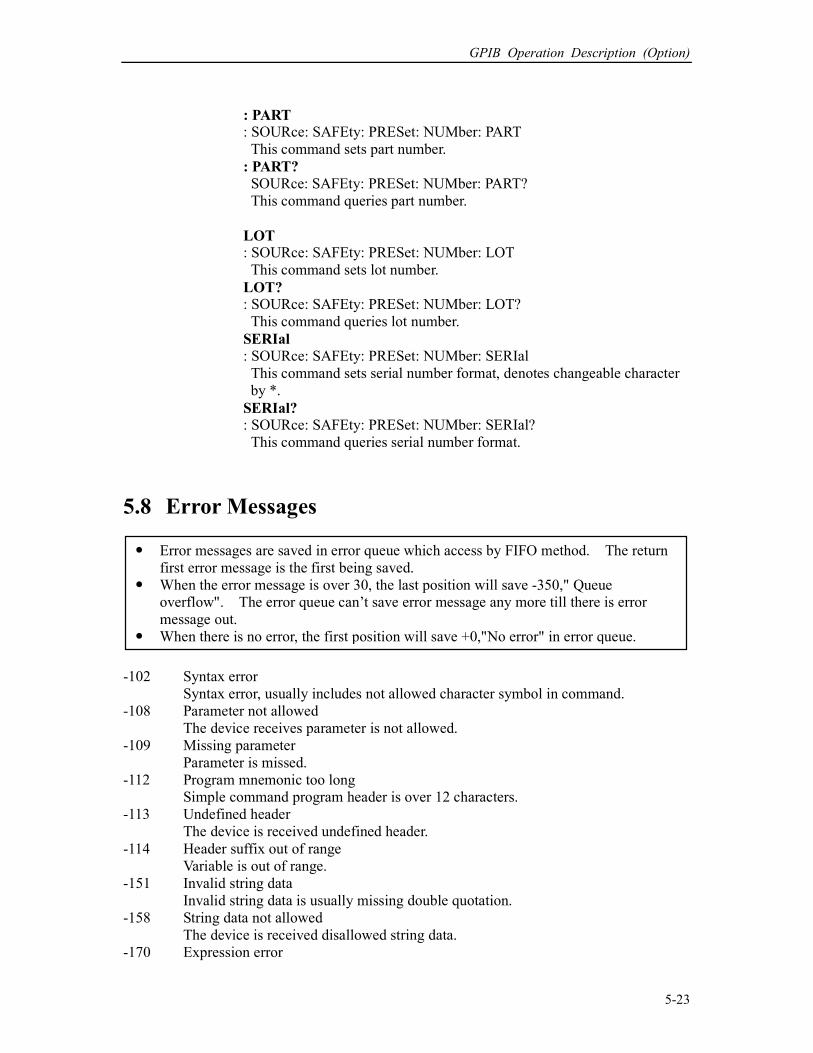
GPIB Operation Description (Option)
5-23
: PART : SOURce: SAFEty: PRESet: NUMber: PART
This command sets part number.
: PART?
SOURce: SAFEty: PRESet: NUMber: PART?
This command queries part number.
LOT : SOURce: SAFEty: PRESet: NUMber: LOT
This command sets lot number.
LOT? : SOURce: SAFEty: PRESet: NUMber: LOT?
This command queries lot number.
SERIal
: SOURce: SAFEty: PRESet: NUMber: SERIal
This command sets serial number format, denotes changeable character
by *.
SERIal? : SOURce: SAFEty: PRESet: NUMber: SERIal?
This command queries serial number format.
5.8 Error Messages
-102 Syntax error
Syntax error, usually includes not allowed character symbol in command.
-108 Parameter not allowed
The device receives parameter is not allowed.
-109 Missing parameter
Parameter is missed.
-112 Program mnemonic too long
Simple command program header is over 12 characters.
-113 Undefined header
The device is received undefined header.
-114 Header suffix out of range
Variable is out of range.
-151 Invalid string data
Invalid string data is usually missing double quotation.
-158 String data not allowed
The device is received disallowed string data.
-170 Expression error
Error messages are saved in error queue which access by FIFO method. The return
first error message is the first being saved.
When the error message is over 30, the last position will save -350," Queue
overflow". The error queue can’t save error message any more till there is error
message out.
When there is no error, the first position will save +0,"No error" in error queue.
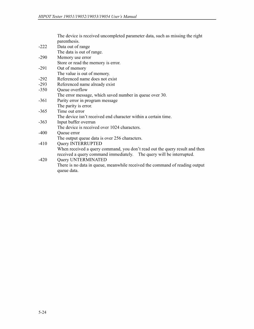
HIPOT Tester 19051/19052/19053/19054 User’s Manual
5-24
The device is received uncompleted parameter data, such as missing the right
parenthesis.
-222 Data out of range
The data is out of range.
-290 Memory use error
Store or read the memory is error.
-291 Out of memory
The value is out of memory.
-292 Referenced name does not exist
-293 Referenced name already exist
-350 Queue overflow
The error message, which saved number in queue over 30.
-361 Parity error in program message
The parity is error.
-365 Time out error
The device isn’t received end character within a certain time.
-363 Input buffer overrun
The device is received over 1024 characters.
-400 Queue error
The output queue data is over 256 characters.
-410 Query INTERRUPTED
When received a query command, you don’t read out the query result and then
received a query command immediately. The query will be interrupted.
-420 Query UNTERMINATED
There is no data in queue, meanwhile received the command of reading output
queue data.
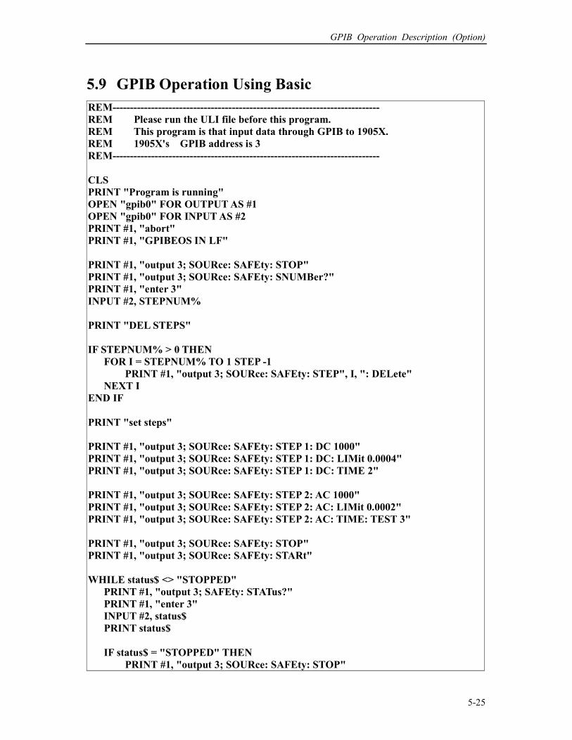
GPIB Operation Description (Option)
5-25
5.9 GPIB Operation Using Basic
REM----------------------------------------------------------------------------
REM Please run the ULI file before this program.
REM This program is that input data through GPIB to 1905X.
REM 1905X's GPIB address is 3
REM----------------------------------------------------------------------------
CLS
PRINT "Program is running"
OPEN "gpib0" FOR OUTPUT AS #1
OPEN "gpib0" FOR INPUT AS #2
PRINT #1, "abort"
PRINT #1, "GPIBEOS IN LF"
PRINT #1, "output 3; SOURce: SAFEty: STOP"
PRINT #1, "output 3; SOURce: SAFEty: SNUMBer?"
PRINT #1, "enter 3"
INPUT #2, STEPNUM%
PRINT "DEL STEPS"
IF STEPNUM% > 0 THEN
FOR I = STEPNUM% TO 1 STEP -1
PRINT #1, "output 3; SOURce: SAFEty: STEP", I, ": DELete"
NEXT I
END IF
PRINT "set steps"
PRINT #1, "output 3; SOURce: SAFEty: STEP 1: DC 1000"
PRINT #1, "output 3; SOURce: SAFEty: STEP 1: DC: LIMit 0.0004"
PRINT #1, "output 3; SOURce: SAFEty: STEP 1: DC: TIME 2"
PRINT #1, "output 3; SOURce: SAFEty: STEP 2: AC 1000"
PRINT #1, "output 3; SOURce: SAFEty: STEP 2: AC: LIMit 0.0002"
PRINT #1, "output 3; SOURce: SAFEty: STEP 2: AC: TIME: TEST 3"
PRINT #1, "output 3; SOURce: SAFEty: STOP"
PRINT #1, "output 3; SOURce: SAFEty: STARt"
WHILE status$ <> "STOPPED"
PRINT #1, "output 3; SAFEty: STATus?"
PRINT #1, "enter 3"
INPUT #2, status$
PRINT status$
IF status$ = "STOPPED" THEN
PRINT #1, "output 3; SOURce: SAFEty: STOP"
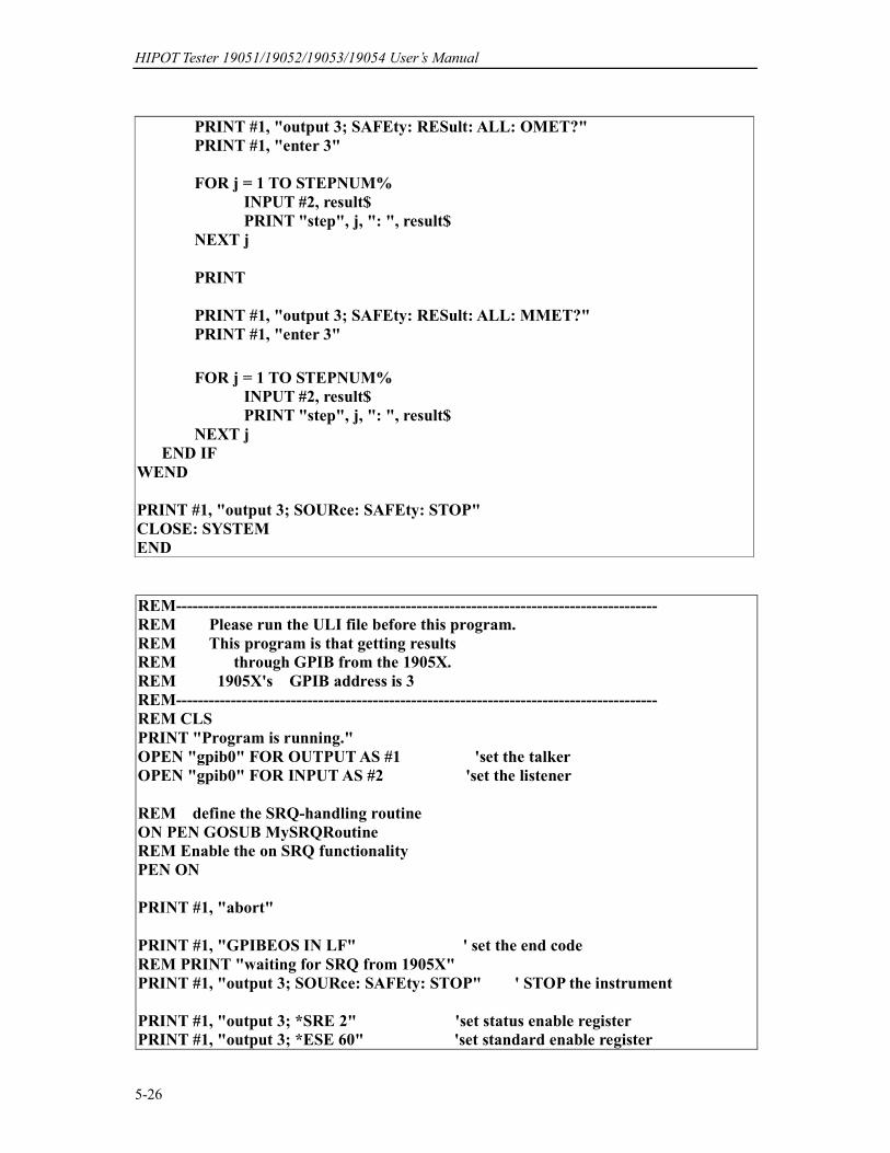
HIPOT Tester 19051/19052/19053/19054 User’s Manual
5-26
PRINT #1, "output 3; SAFEty: RESult: ALL: OMET?"
PRINT #1, "enter 3"
FOR j = 1 TO STEPNUM%
INPUT #2, result$
PRINT "step", j, ": ", result$
NEXT j
PRINT #1, "output 3; SAFEty: RESult: ALL: MMET?"
PRINT #1, "enter 3"
FOR j = 1 TO STEPNUM%
INPUT #2, result$
PRINT "step", j, ": ", result$
NEXT j
END IF
WEND
PRINT #1, "output 3; SOURce: SAFEty: STOP"
CLOSE: SYSTEM
END
REM----------------------------------------------------------------------------------------
REM Please run the ULI file before this program.
REM This program is that getting results
REM through GPIB from the 1905X.
REM 1905X's GPIB address is 3
REM----------------------------------------------------------------------------------------
REM CLS
PRINT "Program is running."
OPEN "gpib0" FOR OUTPUT AS #1 'set the talker
OPEN "gpib0" FOR INPUT AS #2 'set the listener
REM define the SRQ-handling routine
ON PEN GOSUB MySRQRoutine
REM Enable the on SRQ functionality
PEN ON
PRINT #1, "abort"
PRINT #1, "GPIBEOS IN LF" ' set the end code
REM PRINT "waiting for SRQ from 1905X"
PRINT #1, "output 3; SOURce: SAFEty: STOP" ' STOP the instrument
PRINT #1, "output 3; *SRE 2" 'set status enable register
PRINT #1, "output 3; *ESE 60" 'set standard enable register

GPIB Operation Description (Option)
5-27
PRINT #1, "output 3; SOURce: SAFEty: STARt"
FOR I = 1 TO 10000
PRINT "Please wait for SRQ ", I
NEXT I
PRINT "Program is stopped!"
GOTO END1
MySRQRoutine: ' SRQ interrupt
PEN OFF
PRINT "Running the SRQ"
PRINT #1, "output 3;*STB?"
PRINT #1, "enter 3"
INPUT #2, Q$ 'get the questionable state
PRINT Q$
RES = CVI (Q$)
IF RES AND 2 = 2 THEN
PRINT "HAS RESULT!"
END IF 'End of SRQ interrupt
END1:
PRINT #1, "output 3; SOURce: SAFEty: RESult: LAST: JUDGment?"
PRINT #1, "enter 3"
INPUT #2, S$ ' get the questionable state
PRINT S$
PRINT #1, "output 3;*STB?"
PRINT #1, "enter 3"
INPUT #2, Q$ ' get the questionable state
PRINT Q$
CLOSE : SYSTEM
HIPOT Tester 19051/19052/19053/19054 User’s Manual
5-28
REM ------------------------------------------------------------
'Please run the ULI file before this program
'1905X GPIB address is 3
REM ------------------------------------------------------------
OPEN "gpib0" FOR OUTPUT AS #1
OPEN "gpib0" FOR INPUT AS #2
PRINT #1, "abort"
PRINT #1, "GPIBEOS IN LF"
PRINT #1, "output 3; SOURce: SAFEty: STOP"
PRINT #1, "output 3; SOURce: SAFEty: STEP1: AC: LEVel 600"
PRINT #1, "output 3; SOURce: SAFEty: STEP1: AC: LIMit: HIGH 0.0004"
PRINT #1, "output 3; SOURce: SAFEty: STEP2: AC: LEVel 500"
PRINT #1, "output 3; SOURce: SAFEty: STEP2: AC: LIMit: HIGH 0.0003"
'Work memory were stored in memory AAA.
PRINT #1, "output 3; *SAV 1"
PRINT #1, "output 3; MEMory: STATe: DEFine AAA,1"
'Work memory were stored in memory 1.
PRINT #1, "output 3; SOURce: SAFEty: STEP3: DC: LEVel 700"
PRINT #1, "output 3; SOURce: SAFEty: STEP3: DC: LIMit: HIGH 0.01"
PRINT #1, "output 3; SOURce: SAFEty: STEP4: IR: LEVel 800"
PRINT #1, "output 3; SOURce: SAFEty: STEP4: IR: LIMit: HIGH 5000000"
PRINT #1, "output 3; *SAV 3"
PRINT #1, "output 3; MEMory: STATe: DEFine BBB, 3"
'Work memory were stored in memory 3.
'PRINT #1, "output 3; MEMory: STORe: NAME BBB"
'Work memory were stored in memory BBB.
PRINT #1, "output 3; *RCL 1" 'Recall the memory 1
'PRINT #1, "output 3; MEMory: RECAll: NAME AAA" 'Recall the memory AAA
CLOSE: SYSTEM
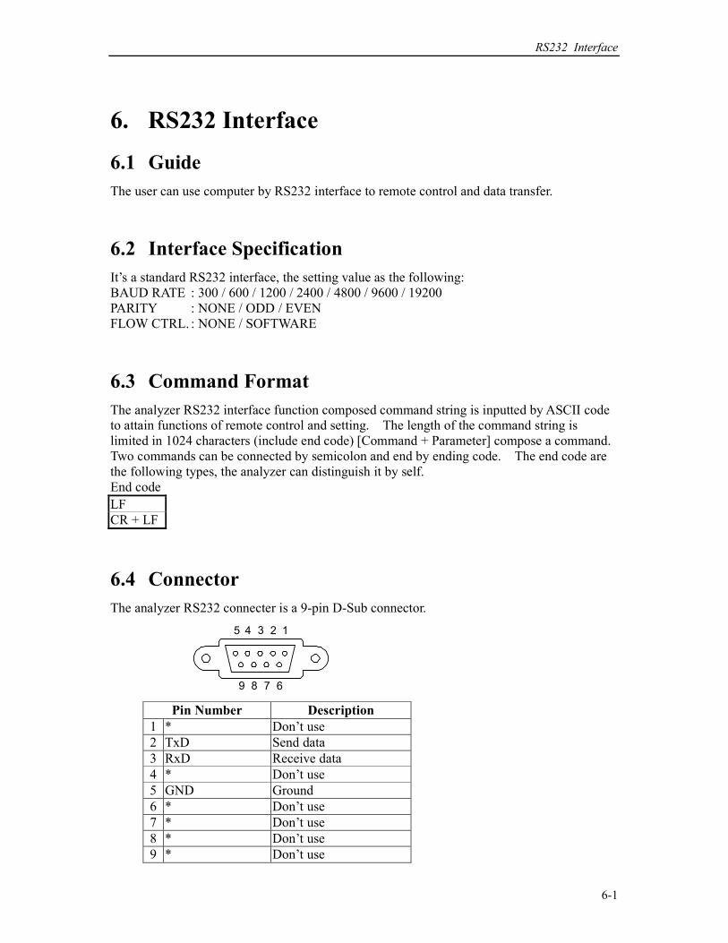
RS232 Interface
6-1
6. RS232 Interface
6.1 Guide
The user can use computer by RS232 interface to remote control and data transfer.
6.2 Interface Specification
It’s a standard RS232 interface, the setting value as the following:
BAUD RATE : 300 / 600 / 1200 / 2400 / 4800 / 9600 / 19200
PARITY : NONE / ODD / EVEN
FLOW CTRL. : NONE / SOFTWARE
6.3 Command Format
The analyzer RS232 interface function composed command string is inputted by ASCII code
to attain functions of remote control and setting. The length of the command string is
limited in 1024 characters (include end code) [Command + Parameter] compose a command.
Two commands can be connected by semicolon and end by ending code. The end code are
the following types, the analyzer can distinguish it by self.
End code
LF
CR + LF
6.4 Connector
The analyzer RS232 connecter is a 9-pin D-Sub connector.
12345
6789
Pin Number Description
1 * Don’t use
2 TxD Send data
3 RxD Receive data
4 * Don’t use
5 GND Ground
6 * Don’t use
7 * Don’t use
8 * Don’t use
9 * Don’t use
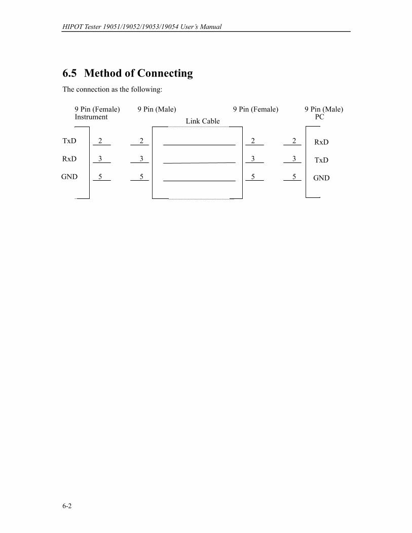
HIPOT Tester 19051/19052/19053/19054 User’s Manual
6-2
6.5 Method of Connecting
The connection as the following:
9 Pin (Male) 9 Pin (Female)
Link Cable
2
3
5
2
3
5
9 Pin (Male) PC
RxD
TxD
GND
2
3
5
2
3
5
9 Pin (Female) Instrument
TxD
RxD
GND
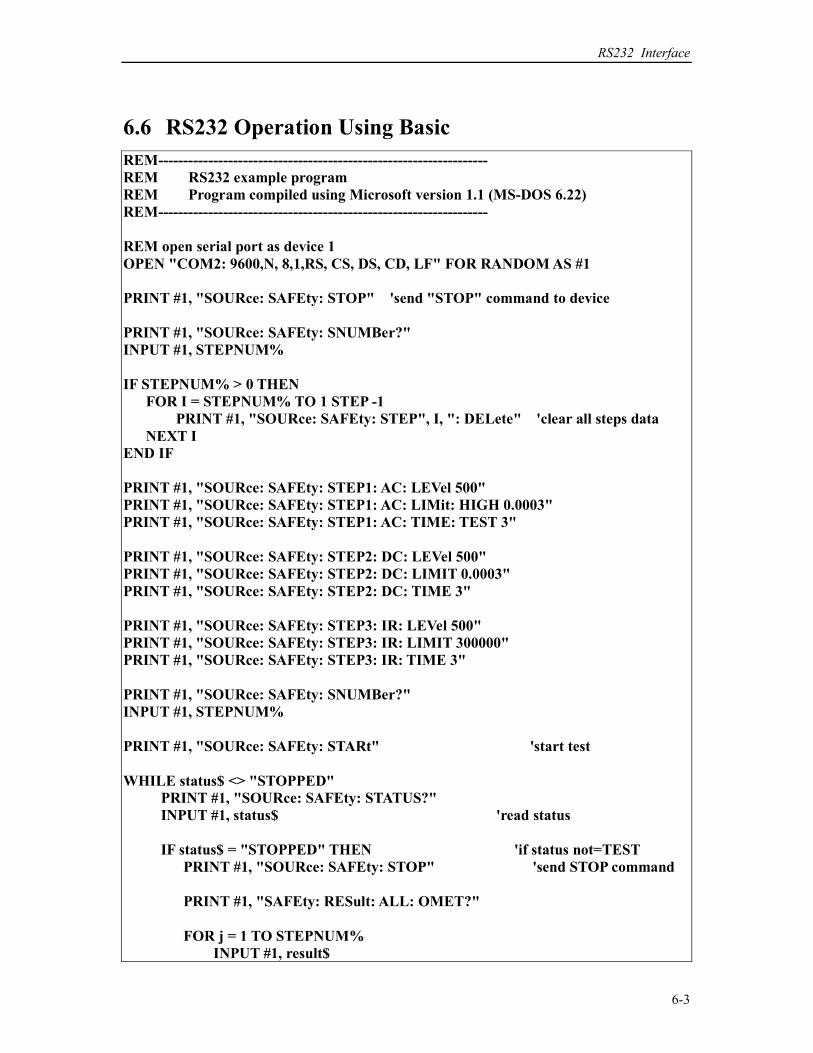
RS232 Interface
6-3
6.6 RS232 Operation Using Basic
REM------------------------------------------------------------------
REM RS232 example program
REM Program compiled using Microsoft version 1.1 (MS-DOS 6.22)
REM------------------------------------------------------------------
REM open serial port as device 1
OPEN "COM2: 9600,N, 8,1,RS, CS, DS, CD, LF" FOR RANDOM AS #1
PRINT #1, "SOURce: SAFEty: STOP" 'send "STOP" command to device
PRINT #1, "SOURce: SAFEty: SNUMBer?"
INPUT #1, STEPNUM%
IF STEPNUM% > 0 THEN
FOR I = STEPNUM% TO 1 STEP -1
PRINT #1, "SOURce: SAFEty: STEP", I, ": DELete" 'clear all steps data
NEXT I
END IF
PRINT #1, "SOURce: SAFEty: STEP1: AC: LEVel 500"
PRINT #1, "SOURce: SAFEty: STEP1: AC: LIMit: HIGH 0.0003"
PRINT #1, "SOURce: SAFEty: STEP1: AC: TIME: TEST 3"
PRINT #1, "SOURce: SAFEty: STEP2: DC: LEVel 500"
PRINT #1, "SOURce: SAFEty: STEP2: DC: LIMIT 0.0003"
PRINT #1, "SOURce: SAFEty: STEP2: DC: TIME 3"
PRINT #1, "SOURce: SAFEty: STEP3: IR: LEVel 500"
PRINT #1, "SOURce: SAFEty: STEP3: IR: LIMIT 300000"
PRINT #1, "SOURce: SAFEty: STEP3: IR: TIME 3"
PRINT #1, "SOURce: SAFEty: SNUMBer?"
INPUT #1, STEPNUM%
PRINT #1, "SOURce: SAFEty: STARt" 'start test
WHILE status$ <> "STOPPED"
PRINT #1, "SOURce: SAFEty: STATUS?"
INPUT #1, status$ 'read status
IF status$ = "STOPPED" THEN 'if status not=TEST
PRINT #1, "SOURce: SAFEty: STOP" 'send STOP command
PRINT #1, "SAFEty: RESult: ALL: OMET?"
FOR j = 1 TO STEPNUM%
INPUT #1, result$
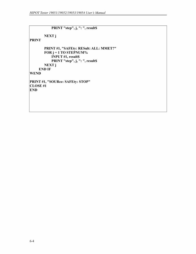
HIPOT Tester 19051/19052/19053/19054 User’s Manual
6-4
PRINT "step", j, ": ", result$
NEXT j
PRINT #1, "SAFEty: RESult: ALL: MMET?"
FOR j = 1 TO STEPNUM%
INPUT #1, result$
PRINT "step", j, ": ", result$
NEXT j
END IF
WEND
PRINT #1, "SOURce: SAFEty: STOP"
CLOSE #1
END
Bar Code Scan Test (Option)
7-1
7. Bar Code Scan Test (Option)
7.1 Guide
The user can use bar code scanner by RS232 interface to remote control and automatic test.
7.2 Interface Specification
The standard RS232 interface.
7.3 Method of Connecting
Please see the Description of RS232 Interface.
7.4 Method of Using
Set the product serial number under PRESET menu screen.
1. The setting characters of product serial number are 5 ∼ 13.
2. The character can be set are 0 ~ 9, A ~ Z, —, *
3. * means changeable character.
4. There is at least a non “ * ” character in string of product serial number.
5. The setting string number of product serial number is the same as the string number of bar
code.
Ex.1: Bar code string 9789572218488
Product serial number can be set as: 9************
or *******2*****
or ************8
Ex. 2: Bar code string C12345
Product serial number can be set as: C*****
or *****5
Ex. 3: Bar code string 12–34–56
Product serial number can be set as: 1*******
or **–*****
If the string scanned from bar code is the same as the product serial number, then will start
test automatically

Printer Function
8-1
8. Printer Function
Preface The user can connect printer (any brand printer except HP) to print test parameter setting
value or test result report.
How to print test parameter setting value? 1. Under power-on screen, press Function Key F3 MENU then move cursor to 8. PRINT
PROGRAM.
2. Press Function Key F3 SELECT , connect correct printer then will auto print test
parameter setting value in memory.
How to print test result report? After setting printer print parameter, follow normal test procedures to test. When test is
completed according to the user setting, connect correct printer to print out test result report.
Enter printer print parameter setting screen.
1. Under power-on screen, press Function Key MENU then move cursor to 3. OPTION.
2. Press Function Key SELECT , then move cursor to 3. PRINT.
3. Press Function Key F3 SELECT , then start to set print parameter.
How to set printer print parameter? 1. By using Function Keys UP, DOWN to set every parameter data.
2. By using Function Key ENTER to move cursor.
3. By using Function Key EXIT to exit this screen.
Print parameter description
A. AUTO PRINT -- includes the following two parameters for setting print test result report
timing.
1. PASS : OFF -- When setting is ON, test result is PASS will print test result report.
2. FAIL : OFF- - When setting is ON, test result is FAIL will print test result report.
3. F .FEED : OFF -- When setting is ON, end the print and printing paper will skip another
page.
B. PRINT DATA - - Includes the following five parameters for setting print test result report
included data.
1. PART NO. : OFF- - When setting is ON, test result report will print PART NUMBER.
2. LOT NO. : OFF- - When setting is ON, test result report will print LOT NUMBER.
3. SERIAL NO. : OFF- - When setting is ON, test result report will print SERIAL
NUMBER.
4. TEST DATA : OFF- - When setting is ON, test result report will print test voltage,
current / resistance value.
5. RESULT : OFF- - when setting is ON, test result report will print test result is PASS
or FAIL.


Calibration Procedure
9-1
9. Calibration Procedure Before process this section the HI-POT tester be warm up at least 30 minutes. Take off the
calibration front panel. Press the lock switch, this is a hardware data backup protection
circuit, to avoid calibration data loss.
The following items are need to calibration.
Voltage Calibration (See 9.2) ACV 5kV Offset (100V) ; AC Voltage OFFSET point
ACV 5kV Full (4kV) ; AC Voltage FULL point
DCV 6kV Offset (100V) ; DC Voltage OFFSET point
DCV 6kV Full (4kV) ; DC Voltage FULL point
IRV 1kV Offset (100V) ; IR Voltage OFFSET point
IRV 1kV Full (1kV) ; IR Voltage FULL point
Current Calibration (See 9.3) ACA 3mA Offset (0.12mA) ; AC total current 2.99mA range OFFSET point
ACA 3mA Full (2.5mA) ; AC total current 2.99mA range FULL point
ACA30mA Offset (2.5mA) ; AC total current 30mA range OFFSET point
ACA 30mA Full (25mA) ; AC total current 30mA range FULL point
RACA 3mA Offset (0.12mA) ; AC real current 2.99mA range OFFSET point
RACA 3mA Full (2.5mA) ; AC real current 2.99mA range FULL point
RACA 30mA Offset (2.5mA) ; AC real current 30mA range OFFSET point
RACA 30mA Full (25mA) ; AC real current 30mA range FULL point
DCA 3mA Offset (0.12mA) ; DC 2.99mA range OFFSET point
DCA 3mA Full (2.5mA) ; DC 2.99mA range FULL point
DCA 10mA Offset (2.5mA) ; DC 10mA range OFFSET point
DCA 10mA Full (8mA) ; DC 10mA range FULL point
Withstanding Voltage Mode ARCing Calibration (See 9.4)
AC ARC 15mA (5mA) ; AC ARCing calibration
DC ARC 10mA (5mA) ; DC ARCing calibration
Insulation Resistance Mode Leakage Current Meter Calibration (See 9.5) IRR Range1 (1GΩ) ; IR Resistor range 1 Calibration
IRR Range2 (100MΩ) ; IR Resistor range 2 Calibration
IRR Range3 (10MΩ) ; IR Resistor range 3 Calibration
IRR Range4 (10MΩ) ; IR Resistor range 4 Calibration
Ground Continue Calibration (See 9.6)
Contrast Calibration (See 9.7)
HIPOT Tester 19051/19052/19053/19054 User’s Manual
9-2
9.1 Calibration
press [MENU] [DOWN] [DOWN] [DOWN]
display CALIBRATION
press [ENTER]
display password
press [A] [A] [A] [B] [ENTER]
9.2 Voltage Calibration
9.2.1 ACV Calibration
Connect an ACV HI voltage meter to HI-POT tester.
press [UP] or [DOWN] key times to display
display ACV 5kv Offset (100V) ; ACV Voltage Offset calibration
press [STOP] [START] ; read out HV meter value
; example 0. 105kV
press [UP] or [DOWN] key until display 0. 105 kV
press [ENTER] for saving calibration value.
press [STOP] ; stop ACV voltage offset calibration
press [UP] key
display ACV 5kV Full (4kV) ; ACV Voltage full scale calibration
press [STOP] [START] ; read out the HV meter value
; example 4.152kV
press [UP] or [DOWN] key until display 4.152 kV
press [ENTER] for saving calibration value.
press [STOP] ; stop ACV voltage full scale
calibration
9.2.2 DCV Calibration
Connect a DCV HI voltage meter to HI-POT tester.
press [UP] key
display DCV 6kV Offset ( 100V ) ; DCV voltage Offset calibration
press [STOP] [START] ; read out HV meter value
; example 0.105kV
press [UP] or [DOWN] key until display 0. 105 kV
press [ENTER] for saving calibration value.
press [STOP] ; stop DCV voltage offset calibration
press [UP] key
display DCV 6kV Full ( 4kV ) ; DCV Voltage full scale calibration
press [STOP] [START] ; read out HV meter value
; example 4.152kV
press [UP] or [DOWN] key until display 4.152 kV
Calibration Procedure
9-3
press [ENTER] for saving calibration value.
press [STOP] ; stop DCV voltage full scale
calibration
9.2.3 IR Voltage Calibration
Connect a DCV HI voltage meter to HI-POT tester.
press [UP] key
display IRV 1kV Offset ( 100V ) ; IR voltage Offset calibration
press [STOP] [START] ; read out HV meter value
; example 0. 105kV
press [UP] or [DOWN] key until display 0. 105 kV
press [ENTER] for saving calibration value.
press [STOP] ; stop IR voltage Offset calibration
press [UP] key to display
display IRV 1kV Full ( 1kV ) ; IR voltage full scale calibration
press [STOP] [START] ; read out HV meter value
; example 1.052kV
press [UP] or [DOWN] key until display 1.052 kV
press [ENTER] for saving calibration value.
press [STOP] ; stop IR voltage full scale calibration
9.3 Current Calibration
Caution! The dummy load must be between HI terminal and ammeter input terminal. Or,
dangerous may be happened.
9.3.1 AC Current Calibration
Connect a dummy load resistor 10MΩ between HI-POT testers. Connect HI terminal to AC
ammeter input HI terminal, connect LO terminal of HI-POT tester to input LO terminal of AC
ammeter.
press [UP] key
display ACA 3mA offset (0.12mA) ; ACA 2.99mA range Offset calibration
press [STOP] [START] ; read out the ammeter value
; example 0.124mA
press [UP] or [DOWN] key until display 0. 124mA
press [ENTER] for saving calibration value.
press [STOP] ; stop ACA 2.999mA range Offset
calibration
Change the dummy load resistor to 500kohm 50watt or higher.
press [UP]
display ACA 3mA Full (2.5mA) ; ACA 2.999mA range full scale
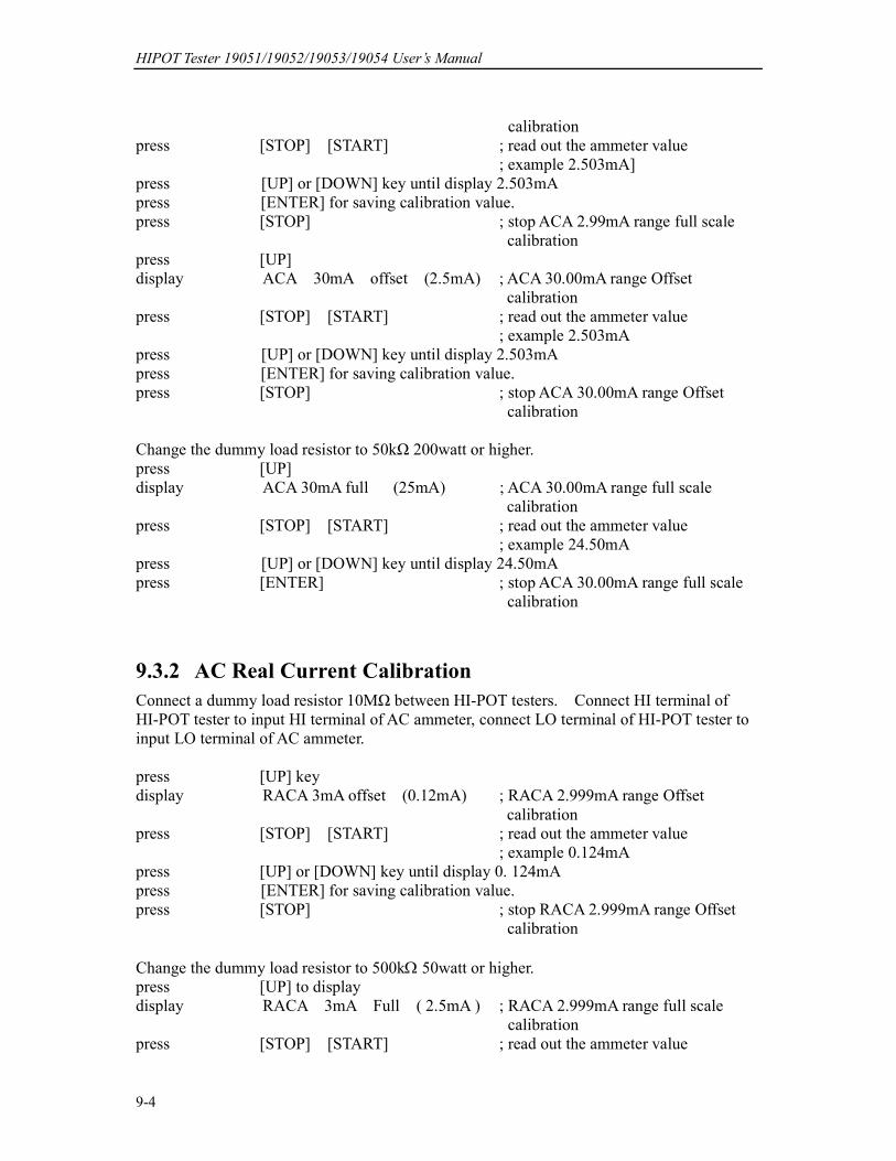
HIPOT Tester 19051/19052/19053/19054 User’s Manual
9-4
calibration
press [STOP] [START] ; read out the ammeter value
; example 2.503mA]
press [UP] or [DOWN] key until display 2.503mA
press [ENTER] for saving calibration value.
press [STOP] ; stop ACA 2.99mA range full scale
calibration
press [UP]
display ACA 30mA offset (2.5mA) ; ACA 30.00mA range Offset
calibration
press [STOP] [START] ; read out the ammeter value
; example 2.503mA
press [UP] or [DOWN] key until display 2.503mA
press [ENTER] for saving calibration value.
press [STOP] ; stop ACA 30.00mA range Offset
calibration
Change the dummy load resistor to 50kΩ 200watt or higher.
press [UP]
display ACA 30mA full (25mA) ; ACA 30.00mA range full scale
calibration
press [STOP] [START] ; read out the ammeter value
; example 24.50mA
press [UP] or [DOWN] key until display 24.50mA
press [ENTER] ; stop ACA 30.00mA range full scale
calibration
9.3.2 AC Real Current Calibration
Connect a dummy load resistor 10MΩ between HI-POT testers. Connect HI terminal of
HI-POT tester to input HI terminal of AC ammeter, connect LO terminal of HI-POT tester to
input LO terminal of AC ammeter.
press [UP] key
display RACA 3mA offset (0.12mA) ; RACA 2.999mA range Offset
calibration
press [STOP] [START] ; read out the ammeter value
; example 0.124mA
press [UP] or [DOWN] key until display 0. 124mA
press [ENTER] for saving calibration value.
press [STOP] ; stop RACA 2.999mA range Offset
calibration
Change the dummy load resistor to 500kΩ 50watt or higher.
press [UP] to display
display RACA 3mA Full ( 2.5mA ) ; RACA 2.999mA range full scale
calibration
press [STOP] [START] ; read out the ammeter value
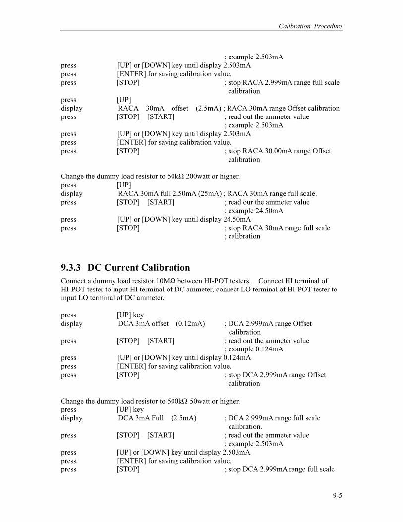
Calibration Procedure
9-5
; example 2.503mA
press [UP] or [DOWN] key until display 2.503mA
press [ENTER] for saving calibration value.
press [STOP] ; stop RACA 2.999mA range full scale
calibration
press [UP]
display RACA 30mA offset (2.5mA) ; RACA 30mA range Offset calibration
press [STOP] [START] ; read out the ammeter value
; example 2.503mA
press [UP] or [DOWN] key until display 2.503mA
press [ENTER] for saving calibration value.
press [STOP] ; stop RACA 30.00mA range Offset
calibration
Change the dummy load resistor to 50kΩ 200watt or higher.
press [UP]
display RACA 30mA full 2.50mA (25mA) ; RACA 30mA range full scale.
press [STOP] [START] ; read our the ammeter value
; example 24.50mA
press [UP] or [DOWN] key until display 24.50mA
press [STOP] ; stop RACA 30mA range full scale
; calibration
9.3.3 DC Current Calibration
Connect a dummy load resistor 10MΩ between HI-POT testers. Connect HI terminal of
HI-POT tester to input HI terminal of DC ammeter, connect LO terminal of HI-POT tester to
input LO terminal of DC ammeter.
press [UP] key
display DCA 3mA offset (0.12mA) ; DCA 2.999mA range Offset
calibration
press [STOP] [START] ; read out the ammeter value
; example 0.124mA
press [UP] or [DOWN] key until display 0.124mA
press [ENTER] for saving calibration value.
press [STOP] ; stop DCA 2.999mA range Offset
calibration
Change the dummy load resistor to 500kΩ 50watt or higher.
press [UP] key
display DCA 3mA Full (2.5mA) ; DCA 2.999mA range full scale
calibration.
press [STOP] [START] ; read out the ammeter value
; example 2.503mA
press [UP] or [DOWN] key until display 2.503mA
press [ENTER] for saving calibration value.
press [STOP] ; stop DCA 2.999mA range full scale

HIPOT Tester 19051/19052/19053/19054 User’s Manual
9-6
calibration.
press [UP] key
display DCA 10mA offset (2.5mA) ; DCA 10.00mA range Offset
calibration.
press [STOP] [START] ; read out the ammeter value
; example 2.503mA
press [UP] or [DOWN] key until display 2.503mA
press [ENTER] for saving calibration value.
press [STOP] ; stop DCA 10.00mA range Offset
calibration.
Change the dummy load resistor to150kΩ 100watt or higher.
press [UP] key to display
display DCA 10mA full (8mA) ; DCA 10.00mA range full scale
calibration.
press [STOP] [START] ; read out the ammeter value
; example 8.02mA
press [UP] or [DOWN] key until display 8.02mA
press [ENTER] for saving calibration value.
press [STOP] ; stop DCA 10.00mA range full scale
calibration.
9.4 Withstanding Voltage Mode ARCing Calibration
! Caution: 1. ARCing calibration is very special, the high voltage terminal are on outside.
2. Please contact your local agent for more detailed descriptions.
press [UP] key ; AC arcing sensitivity calibration.
display AC ARC 15mA (5mA) ; AC hipot ARCing.
press [STOP] [START] ; Using two HV cables, HV output
terminal series 250kΩ 5watt
resistance. Another HV cable
(ground wire RTN/LOW) is as
possible as close to the first one cable
but do not contact each other. Then
press [STOP] [START] to generate
ARCing.
press [UP] or [DOWN] key until ARC NG high limit value is a critical point of
generating ARC NG and non-generating ARC NG.
press [STOP] ; stop AC ARCing calibration.
press [UP] key ; DC ARCing sensitivity calibration
display DC ARC 10mA (5mA) ; DC hipot ARCing.
press [STOP] [START] ; Using two HV cables, HV output
terminal series 250kΩ 5watt
resistance. Another HV cable
(ground wire RTN/LOW) is as
possible as close to the first one cable
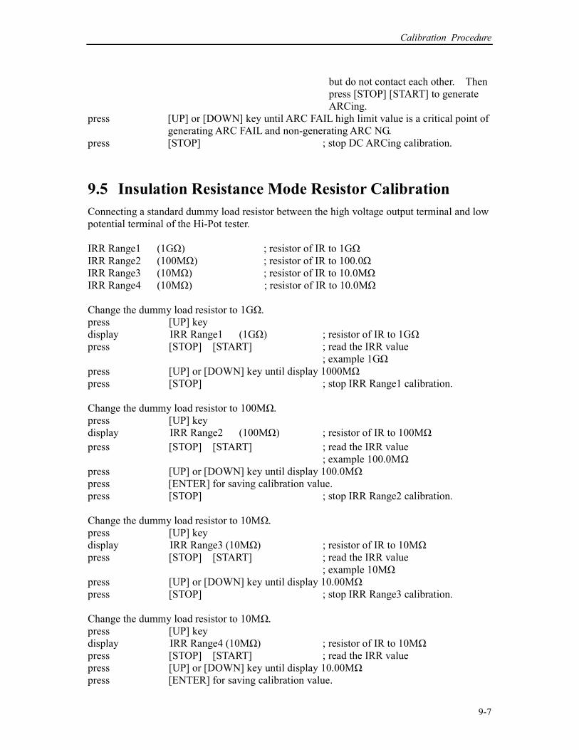
Calibration Procedure
9-7
but do not contact each other. Then
press [STOP] [START] to generate
ARCing.
press [UP] or [DOWN] key until ARC FAIL high limit value is a critical point of
generating ARC FAIL and non-generating ARC NG.
press [STOP] ; stop DC ARCing calibration.
9.5 Insulation Resistance Mode Resistor Calibration
Connecting a standard dummy load resistor between the high voltage output terminal and low
potential terminal of the Hi-Pot tester.
IRR Range1 (1GΩ) ; resistor of IR to 1GΩ
IRR Range2 (100MΩ) ; resistor of IR to 100.0Ω
IRR Range3 (10MΩ) ; resistor of IR to 10.0MΩ
IRR Range4 (10MΩ) ; resistor of IR to 10.0MΩ
Change the dummy load resistor to 1GΩ.
press [UP] key
display IRR Range1 (1GΩ) ; resistor of IR to 1GΩ
press [STOP] [START] ; read the IRR value
; example 1GΩ
press [UP] or [DOWN] key until display 1000MΩ
press [STOP] ; stop IRR Range1 calibration.
Change the dummy load resistor to 100MΩ.
press [UP] key
display IRR Range2 (100MΩ) ; resistor of IR to 100MΩ
press [STOP] [START] ; read the IRR value
; example 100.0MΩ
press [UP] or [DOWN] key until display 100.0MΩ
press [ENTER] for saving calibration value.
press [STOP] ; stop IRR Range2 calibration.
Change the dummy load resistor to 10MΩ.
press [UP] key
display IRR Range3 (10MΩ) ; resistor of IR to 10MΩ
press [STOP] [START] ; read the IRR value
; example 10MΩ
press [UP] or [DOWN] key until display 10.00MΩ
press [STOP] ; stop IRR Range3 calibration.
Change the dummy load resistor to 10MΩ.
press [UP] key
display IRR Range4 (10MΩ) ; resistor of IR to 10MΩ
press [STOP] [START] ; read the IRR value
press [UP] or [DOWN] key until display 10.00MΩ
press [ENTER] for saving calibration value.
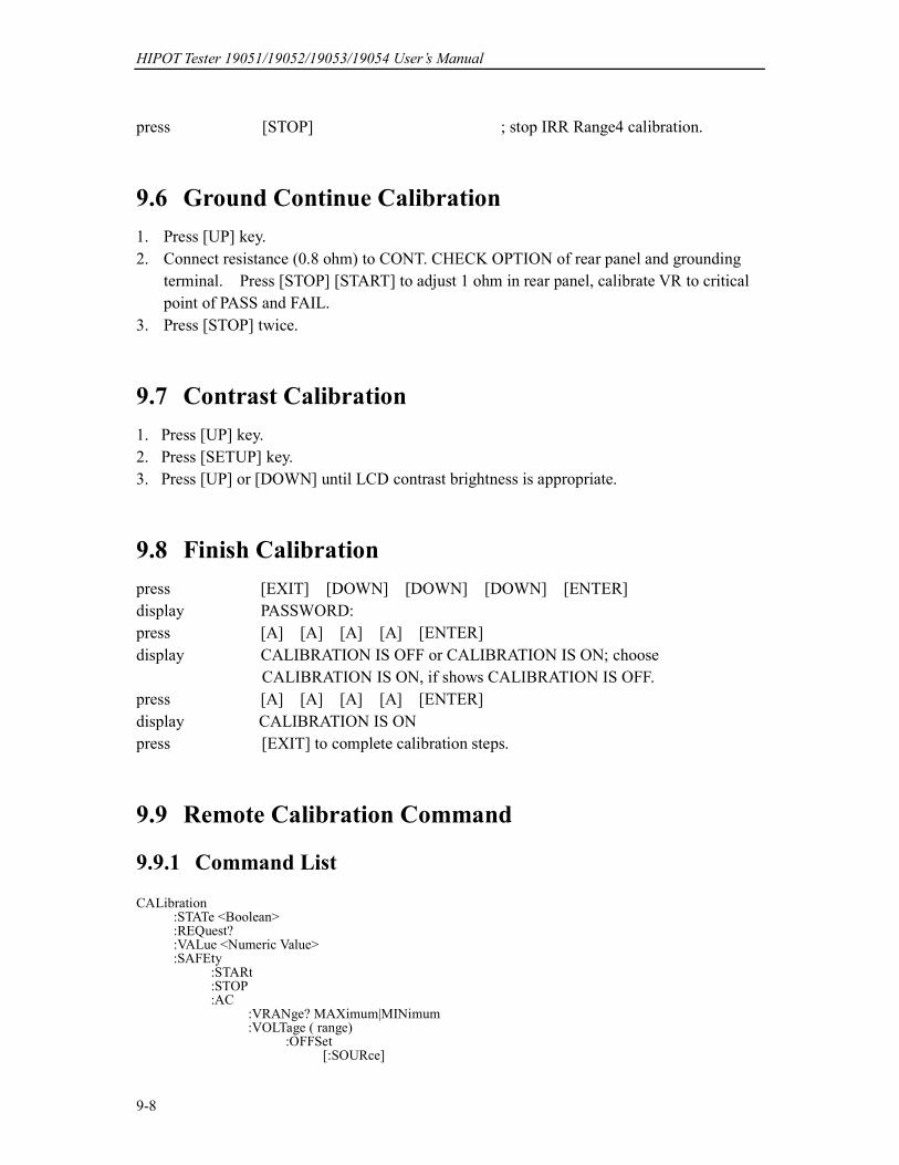
HIPOT Tester 19051/19052/19053/19054 User’s Manual
9-8
press [STOP] ; stop IRR Range4 calibration.
9.6 Ground Continue Calibration
1. Press [UP] key.
2. Connect resistance (0.8 ohm) to CONT. CHECK OPTION of rear panel and grounding
terminal. Press [STOP] [START] to adjust 1 ohm in rear panel, calibrate VR to critical
point of PASS and FAIL.
3. Press [STOP] twice.
9.7 Contrast Calibration
1. Press [UP] key.
2. Press [SETUP] key.
3. Press [UP] or [DOWN] until LCD contrast brightness is appropriate.
9.8 Finish Calibration
press [EXIT] [DOWN] [DOWN] [DOWN] [ENTER]
display PASSWORD:
press [A] [A] [A] [A] [ENTER]
display CALIBRATION IS OFF or CALIBRATION IS ON; choose
CALIBRATION IS ON, if shows CALIBRATION IS OFF.
press [A] [A] [A] [A] [ENTER]
display CALIBRATION IS ON
press [EXIT] to complete calibration steps.
9.9 Remote Calibration Command
9.9.1 Command List
CALibration :STATe <Boolean> :REQuest? :VALue <Numeric Value> :SAFEty :STARt :STOP :AC :VRANge? MAXimum|MINimum :VOLTage ( range) :OFFSet [:SOURce]

Calibration Procedure
9-9
[:VOLTage] [<Numeric Value>] [:VOLTage] ? :BEST? :FULL [:SOURce] [:VOLTage] [<Numeric Value>] [:VOLTage] ? :BEST? :CRANge? MAXimum|MINimum :CURRent ( range) :OFFSet [:SOURce] [:VOLTage] [<Numeric Value>] [:VOLTage] ? :BEST? :FULL [:SOURce] [:VOLTage] [<Numeric Value>] [:VOLTage] ? :BEST? :RCRANge? MAXimum|MINimum :RCURrent ( range) :OFFSet [:SOURce] [:VOLTage] [<Numeric Value>] [:VOLTage] ? :BEST? :FULL [:SOURce] [:VOLTage] [<Numeric Value>] [:VOLTage] ? :BEST? :ARANge? MAXimum|MINimum :ARC ( range) :SLOPe [:SOURce] [:VOLTage] [<Numeric Value>] [:VOLTage] ? :LEVel [<Numeric Value>] :LEVel? :BEST? :DC :VRANge? MAXimum|MINimum :VOLTage ( range) :OFFSet [:SOURce] [:VOLTage] [<Numeric Value>] [:VOLTage] ? :BEST? :FULL [:SOURce] [:VOLTage] [<Numeric Value>] [:VOLTage] ? :BEST? :CRANge? MAXimum|MINimum :CURRent ( range) :OFFSet [:SOURce] [:VOLTage] [<Numeric Value>] [:VOLTage] ? :BEST? :FULL [:SOURce] [:VOLTage] [<Numeric Value>] [:VOLTage] ? :BEST? :ARANge? MAXimum|MINimum :ARC ( range)
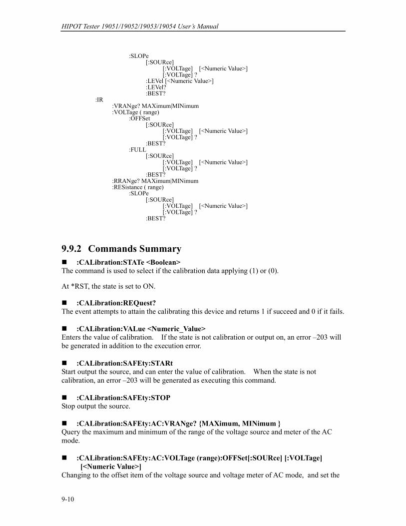
HIPOT Tester 19051/19052/19053/19054 User’s Manual
9-10
:SLOPe [:SOURce] [:VOLTage] [<Numeric Value>] [:VOLTage] ? :LEVel [<Numeric Value>] :LEVel? :BEST? :IR :VRANge? MAXimum|MINimum :VOLTage ( range) :OFFSet [:SOURce] [:VOLTage] [<Numeric Value>] [:VOLTage] ? :BEST? :FULL [:SOURce] [:VOLTage] [<Numeric Value>] [:VOLTage] ? :BEST? :RRANge? MAXimum|MINimum :RESistance ( range) :SLOPe [:SOURce] [:VOLTage] [<Numeric Value>] [:VOLTage] ? :BEST?
9.9.2 Commands Summary
:CALibration:STATe <Boolean> The command is used to select if the calibration data applying (1) or (0).
At *RST, the state is set to ON.
:CALibration:REQuest?
The event attempts to attain the calibrating this device and returns 1 if succeed and 0 if it fails.
:CALibration:VALue <Numeric_Value> Enters the value of calibration. If the state is not calibration or output on, an error –203 will
be generated in addition to the execution error.
:CALibration:SAFEty:STARt Start output the source, and can enter the value of calibration. When the state is not
calibration, an error –203 will be generated as executing this command.
:CALibration:SAFEty:STOP Stop output the source.
:CALibration:SAFEty:AC:VRANge? MAXimum, MINimum Query the maximum and minimum of the range of the voltage source and meter of the AC
mode.
:CALibration:SAFEty:AC:VOLTage (range):OFFSet[:SOURce] [:VOLTage]
[<Numeric Value>]
Changing to the offset item of the voltage source and voltage meter of AC mode, and set the

Calibration Procedure
9-11
output voltage value that is used in the calibration.
:CALibration:SAFEty:AC:VOLTage (range):OFFSet[:SOURce] [:VOLTage] ? Change to the offset item of the voltage source and voltage meter of AC mode, and returns the
output voltage value which is used in the calibration.
:CALibration:SAFEty:AC:VOLTage (range):OFFSet:BEST? Change to the offset item of voltage source and voltage meter of AC mode, and returns the
best value that is selected by device. :CALibration:SAFEty:AC:VOLTage (range):FULL[:SOURce] [:VOLTage]
[<Numeric Value>] Change to the offset item of voltage source and voltage meter of AC mode, and set the output
voltage value that is used in the calibration. :CALibration:SAFEty:AC:VOLTage (range):FULL[:SOURce] [:VOLTage] ?
Change to the offset item of voltage source and voltage meter of AC mode, and returns the
output voltage value which is used in the calibration.
:CALibration:SAFEty:AC:VOLTage (range):FULL:BEST? Change to the offset item of voltage source and voltage meter of AC mode, and returns the best value that is selected by device. :CALibration:SAFEty:AC:CRANge? MAXimum, MINimum Query the maximum and minimum of the range of the current meter of the AC mode. :CALibration:SAFEty:AC:CURRent (range):OFFSet[:SOURce] [:VOLTage]
[<Numeric Value>] Change to the offset item of current meter of AC mode, and set the output voltage value that is
used in the calibration. The header suffix (range) is selected the range of current. :CALibration:SAFEty:AC:CURRent (range):OFFSet[:SOURce] [:VOLTage] ? Change to the offset item of current meter of AC mode, and returns the output voltage value
which is used in the calibration.
:CALibration:SAFEty:AC:CURRent (range):OFFSet:BEST? Change to the offset item of current meter of AC mode, and returns the best value that is
selected by device. :CALibration:SAFEty:AC:CURRent (range):FULL[:SOURce] [:VOLTage]
[<Numeric Value>] Change to the full item of current meter of AC mode, and set the output voltage value that is
used in the calibration. :CALibration:SAFEty:AC:CURRent (range):FULL[:SOURce] [:VOLTage] ?
Change to the full item of current meter of AC mode, and returns the output voltage value
which is used in the calibration.
:CALibration:SAFEty:AC:CURRent (range):FULL:BEST?
HIPOT Tester 19051/19052/19053/19054 User’s Manual
9-12
Change to the full item of current meter of AC mode, and returns the best value that is
selected by device.
:CALibration:SAFEty:AC:RCRAnge? MAXimum, MINimum
Query the maximum and minimum of the range of the real current meter of the AC mode.
:CALibration:SAFEty:AC:RCURrent (range):OFFSet[:SOURce] [:VOLTage]
[<Numeric Value>] Change to the offset item of the real current meter of AC mode, and set the output voltage
value that is used in the calibration. The header suffix (range) is selected the range of
current
:CALibration:SAFEty:AC:RCURrent (range):OFFSet[:SOURce] [:VOLTage] ? Change to the offset item of the real current meter of AC mode, and returns the output voltage
value which is used in the calibration.
:CALibration:SAFEty:AC:RCURrent (range):OFFSet:BEST? Change to the offset item of real current meter of AC mode, and returns the best value that is
selected by device. :CALibration:SAFEty:AC:RCURrent (range):FULL[:SOURce] [:VOLTage]
[<Numeric Value>] Change to the full item of the real current meter of AC mode, and set the output voltage value
that is used in the calibration. :CALibration:SAFEty:AC:RCURrent (range):FULL[:SOURce] [:VOLTage] ?
Change to the full item of the real current meter of AC mode, and returns the output voltage
value which is used in the calibration.
:CALibration:SAFEty:AC:RCURrent (range):FULL:BEST? Change to the full item of real current meter of AC mode, and returns the best value that is
selected by device. :CALibration:SAFEty:AC:ARANge? MAXimum, MINimum Query the maximum and minimum of the range of the arc meter of the AC mode. :CALibration:SAFEty:AC:ARC (range):SLOPe[:SOURce] [:VOLTage]
[<Numeric Value>] Change to the arc item of AC mode, and set the output voltage value that is used in the
calibration.
:CALibration:SAFEty:AC:ARC (range):SLOPe[:SOURce] [:VOLTage] ? Change to the arc item of AC mode, and returns the output voltage value which is used in the
calibration. :CALibration:SAFEty:AC:ARC (range):SLOPe:LEVel [<Numeric Value>] Change to the arc item of AC mode, and set the arc limit value. :CALibration:SAFEty:AC:ARC (range):SLOPe:LEVel?
Change to the arc item of AC mode, and returns the arc limit value.
Calibration Procedure
9-13
:CALibration:SAFEty:AC:ARC (range):SLOPe:BEST? Change to the arc item of AC mode, and returns the best arc limit value that is selected by
device.
:CALibration:SAFEty:DC:VRANge? MAXimum, MINimum Query the maximum and minimum of the range of the voltage source and meter of the DC
mode.
:CALibration:SAFEty:DC:VOLTage (range):OFFSet[:SOURce] [:VOLTage]
[<Numeric Value>] Change to the offset item of the voltage source and voltage meter of DC mode, and set the
output voltage value that is used in the calibration. :CALibration:SAFEty:DC:VOLTage (range):OFFSet[:SOURce] [:VOLTage] ?
Change to the offset item of the voltage source and voltage meter of DC mode, and returns the
output voltage value which is used in the calibration. :CALibration:SAFEty:DC:VOLTage (range):OFFSet:BEST? Change to the offset item of voltage source and voltage meter of DC mode, and returns the
best value that is selected by device. :CALibration:SAFEty:DC:VOLTage (range):FULL[:SOURce] [:VOLTage]
[<Numeric Value>] Change to the offset item of voltage source and voltage meter of DC mode, and set the output
voltage value that is used in the calibration. :CALibration:SAFEty:DC:VOLTage (range):FULL[:SOURce] [:VOLTage] ?
Change to the offset item of voltage source and voltage meter of DC mode, and returns the
output voltage value which is used in the calibration.
:CALibration:SAFEty:DC:VOLTage (range):FULL:BEST? Change to the offset item of voltage source and voltage meter of DC mode, and returns the
best value that is selected by device. :CALibration:SAFEty:DC:CRANge? MAXimum, MINimum Query the maximum and minimum of the range of the current meter of the DC mode. :CALibration:SAFEty:DC:CURRent (range):OFFSet[:SOURce] [:VOLTage]
[<Numeric Value>] Change to the offset item of current meter of DC mode, and set the output voltage value that
is used in the calibration. The header suffix ( range) is selected the range of current :CALibration:SAFEty:DC:CURRent (range):OFFSet[:SOURce] [:VOLTage] ? Change to the offset item of current meter of DC mode, and returns the output voltage value
which is used in the calibration. :CALibration:SAFEty:DC:CURRent (range):OFFSet:BEST? Change to the offset item of current meter of DC mode, and returns the best value that is
selected by device.
HIPOT Tester 19051/19052/19053/19054 User’s Manual
9-14
:CALibration:SAFEty:DC:CURRent (range):FULL[:SOURce] [:VOLTage]
[<Numeric Value>] Change to the full item of current meter of DC mode, and set the output voltage value that is
used in the calibration. :CALibration:SAFEty:DC:CURRent (range):FULL[:SOURce] [:VOLTage] ?
Change to the full item of current meter of DC mode, and returns the output voltage value
which is used in the calibration.
:CALibration:SAFEty:DC:CURRent (range):FULL:BEST? Change to the full item of current meter of DC mode, and returns the best value that is
selected by device. :CALibration:SAFEty:DC:ARANge? MAXimum, MINimum Query the maximum and minimum of the range of the arc meter of the DC mode.
:CALibration:SAFEty:DC:ARC (range):SLOPe[:SOURce] [:VOLTage]
[<Numeric Value>]
Change to the arc item of DC mode, and set the output voltage value that is used in the
calibration.
:CALibration:SAFEty:DC:ARC (range):SLOPe[:SOURce] [:VOLTage] ? Change to the arc item of DC mode, and returns the output voltage value which is used in the
calibration.
:CALibration:SAFEty:DC:ARC (range):SLOPe:LEVel [<Numeric Value>]
Change to the arc item of DC mode, and set the arc limit value.
:CALibration:SAFEty:DC:ARC (range):SLOPe:LEVel? Change to the arc item of DC mode, and returns the arc limit value.
:CALibration:SAFEty:DC:ARC (range):SLOPe:BEST? Changing to the arc item of DC mode, and returns the best arc limit value that is selected by
device.
:CALibration:SAFEty:IR:VRANge? MAXimum, MINimum
Query the maximum and minimum of the range of the voltage source and meter of the IR
mode.
:CALibration:SAFEty:IR:VOLTage (range):OFFSet[:SOURce] [:VOLTage]
[<Numeric Value>] Change to the offset item of the voltage source and voltage meter of IR mode, and set the
output voltage value that is used in the calibration.
:CALibration:SAFEty:IR:VOLTage (range):OFFSet[:SOURce] [:VOLTage] ?
Change to the offset item of the voltage source and voltage meter of IR mode, and returns the
output voltage value which is used in the calibration.
:CALibration:SAFEty:IR:VOLTage (range):OFFSet:BEST? Change to the offset item of voltage source and voltage meter of IR mode, and returns the best
Calibration Procedure
9-15
value that is selected by device.
:CALibration:SAFEty:IR:VOLTage (range):FULL[:SOURce] [:VOLTage]
[<Numeric Value>]
Change to the full item of voltage source and voltage meter of IR mode, and set the output
voltage value that is used in the calibration.
:CALibration:SAFEty:IR:VOLTage (range):FULL[:SOURce] [:VOLTage] ? Change to the full item of voltage source and voltage meter of IR mode, and returns the
output voltage value which is used in the calibration. :CALibration:SAFEty:IR:VOLTage (range):FULL:BEST? Change to the full item of voltage source and voltage meter of IR mode, and returns the best
value that is selected by device.
:CALibration:SAFEty:IR:RRANge? MAXimum, MINimum
Query the maximum and minimum of the range of the resistance meter of the IR mode.
:CALibration:SAFEty:IR:RESistance (range):SLOPe[:SOURce] [:VOLTage]
[<Numeric Value>] Change to the resistance item of IR mode, and set the output voltage value that is used in the
calibration.
:CALibration:SAFEty:IR:RESistance (range):SLOPe[:SOURce] [:VOLTage] ?
Change to the resistance item of IR mode, and returns the output voltage value which is used
in the calibration.
:CALibration:SAFEty:IR:RESistance (range):SLOPe:BEST? Change to the resistance item of IR mode, and returns the best value that is selected by
device.


Maintenance
10-1
10. Maintenance
10.1 General
Our warranty (at the front of the manual) attests the quality of materials and workmanship in
our products. If malfunction should be suspected, or other information be desired
applications engineers are available for technical assistance. Application assistance is
available in the Taiwan by calling 886-3-3279999 and asking for applications support. For
support outside of the Taiwan please contact your local Chroma distributor.
10.2 Instrument Return
Before returning an instrument to Chroma for service please call our Service Department at
886-3-3279688 for return material authorization. It will be necessary to include a purchase
order number to insure expedient processing, although units found to be in warranty will be
repaired at no-charge. For any questions on repair costs or shipment instructions please
contact our service department at the above number. To safeguard an instrument during
storage and shipping please use packaging that is adequate to protect it from damage, i.e.,
equivalent to the original packaging and mark the box "Delicate Electronic Instrument".
Return material should be sent freight prepaid, to:
Chroma Ate Inc.
66 Hwa-Ya 1 Rd., Hwa-Ya Technical Park,
Kuei-Shan Hsiang, Taoyuan Hsien, Taiwan
Attention: Service Department