Hima OPC Server Manual
36
HIMA Manual HIMA OPC A&E Server Version 1.2 Operating systems: Windows XP / Server 2003 / 7 /Server 2008 Valid from A&E Server Version 4.0.1
-
Upload
ashkan-khajouie -
Category
Documents
-
view
392 -
download
52
description
Hima OPC Server Manual
Transcript of Hima OPC Server Manual

HIMA
Manual HIMA OPC A&E Server Version 1.2 Operating systems: Windows XP / Server 2003 / 7 /Server 2008 Valid from A&E Server Version 4.0.1

The information of this document may be changed without prior notice and does not present any obligation for HIMA Paul Hildebrandt GmbH & Co KG. The software described in this document is provided according to a licence or secrecy agreement. The software may only be used or copied corresponding to the agree-ment conditions. The software must not be copied to any other media unless the licence or secrecy agree-ment permit so. No part of this manual may be reproduced or utilized in any form or by any means with re-cording or information storage and retrieval systems without explicit written permission by HIMA. Copyright © 2010 HIMA Paul Hildebrandt GmbH & Co KG. All rights reserved. MS-DOS, Microsoft, Windows and Windows NT are registered trademarks of Microsoft Corporation. All other mark and product names are the property of their respective trademark owners. Printed in Germany Document Number: Handbuch HIMA OPC A&E Server HIMA Paul Hildebrandt GmbH & Co KG http://www.hima.com GERMANY
Manual HIMA OPC A&E Server 3
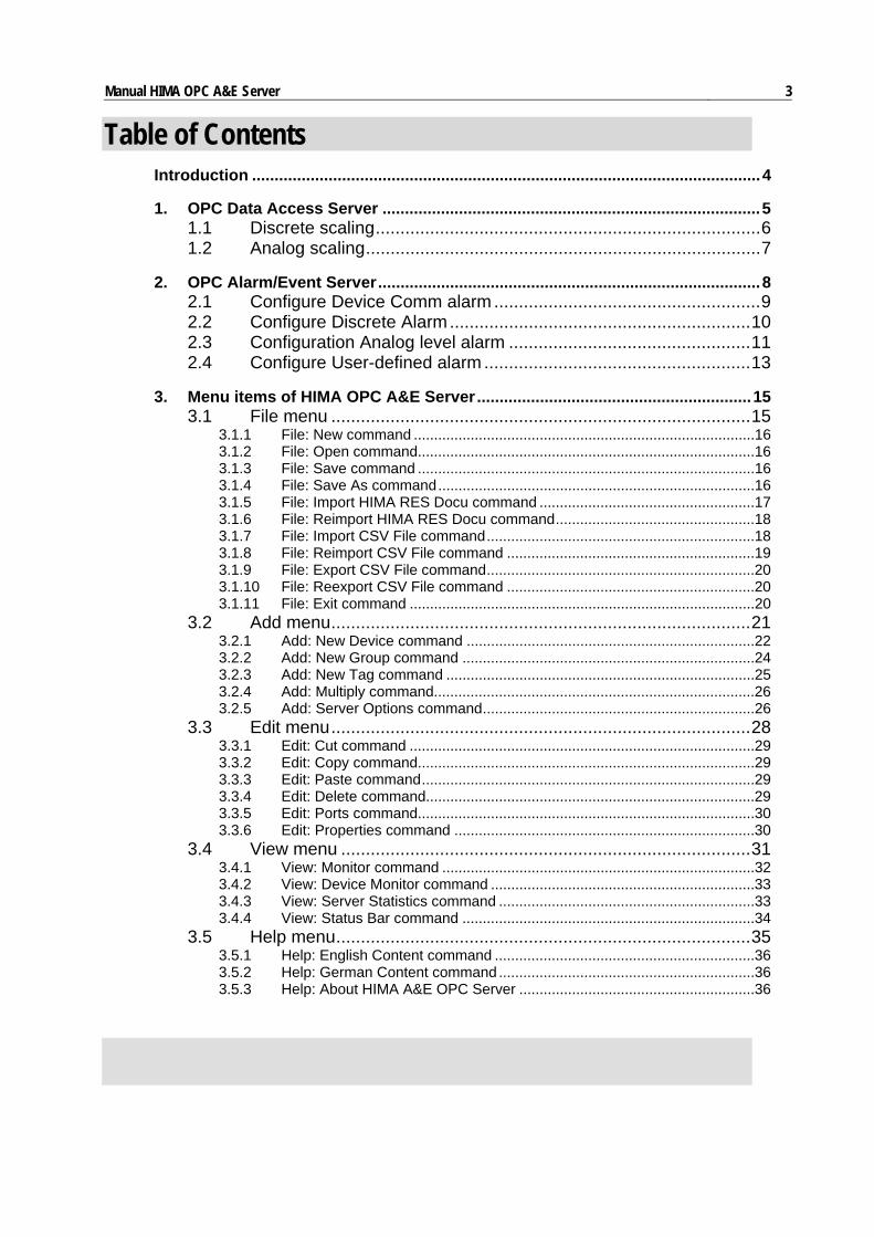
Table of Contents Introduction .................................................................................................................4
1. OPC Data Access Server ....................................................................................5 1.1 Discrete scaling..............................................................................6 1.2 Analog scaling................................................................................7
2. OPC Alarm/Event Server.....................................................................................8 2.1 Configure Device Comm alarm ......................................................9 2.2 Configure Discrete Alarm.............................................................10 2.3 Configuration Analog level alarm .................................................11 2.4 Configure User-defined alarm ......................................................13
3. Menu items of HIMA OPC A&E Server.............................................................15 3.1 File menu .....................................................................................15
3.1.1 File: New command ....................................................................................16 3.1.2 File: Open command...................................................................................16 3.1.3 File: Save command ...................................................................................16 3.1.4 File: Save As command..............................................................................16 3.1.5 File: Import HIMA RES Docu command .....................................................17 3.1.6 File: Reimport HIMA RES Docu command.................................................18 3.1.7 File: Import CSV File command..................................................................18 3.1.8 File: Reimport CSV File command .............................................................19 3.1.9 File: Export CSV File command..................................................................20 3.1.10 File: Reexport CSV File command .............................................................20 3.1.11 File: Exit command .....................................................................................20
3.2 Add menu.....................................................................................21 3.2.1 Add: New Device command .......................................................................22 3.2.2 Add: New Group command ........................................................................24 3.2.3 Add: New Tag command ............................................................................25 3.2.4 Add: Multiply command...............................................................................26 3.2.5 Add: Server Options command...................................................................26
3.3 Edit menu.....................................................................................28 3.3.1 Edit: Cut command .....................................................................................29 3.3.2 Edit: Copy command...................................................................................29 3.3.3 Edit: Paste command..................................................................................29 3.3.4 Edit: Delete command.................................................................................29 3.3.5 Edit: Ports command...................................................................................30 3.3.6 Edit: Properties command ..........................................................................30
3.4 View menu ...................................................................................31 3.4.1 View: Monitor command .............................................................................32 3.4.2 View: Device Monitor command .................................................................33 3.4.3 View: Server Statistics command ...............................................................33 3.4.4 View: Status Bar command ........................................................................34
3.5 Help menu....................................................................................35 3.5.1 Help: English Content command ................................................................36 3.5.2 Help: German Content command...............................................................36 3.5.3 Help: About HIMA A&E OPC Server ..........................................................36

Manual HIMA OPC A&E Server 4
Introduction
The HIMA OPC-A&E-Server provides the OPC interface and communication facility for well- known standard HIMA H41/H51q and PLANAR 4 devices supporting Modbus slave data output. The OPC Server has a Windows style common menu and user interface scheme. Some dialog boxes and its controls will appear however according to the current OPC device and communication protocol rules and properties. The current OPC window workspace is al-ways divided on two views like Windows Explorer: a tree view for devices and groups and a list view for tags. A tree view can be seen on the left side to show the defined devices and groups in their hi-erarchy. The user has some interactive control possibilities to open or close hierarchy lay-ers to see them globally (by name only) or detailed. The user can add new devices, new groups or change parameters on existing devices. On the right side of the workspace there is a list view where the tags of the lastly selected tree view node are always seen with their main properties. Most of menu items can be accessed by toolbar buttons or keyboard accelerator combina-tions of the Ctrl key and a letter key.
The HIMA OPC A&E Server provides an OPC Data Access Server with data access inter-faces 1.0 and 2.0. All HIMA process point can be represented as data tags in this server. Each data tag has alarm properties so the program provides an OPC Alarm/Event Server applied to specification 1.10.
OPC Data Access Server OPC Alarm/Event Server
The program’s user interface has the following menus for actions:
File Add Edit View Help
Manual HIMA OPC A&E Server 5
1. OPC Data Access Server
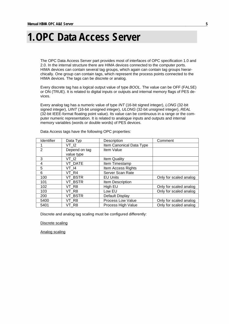
The OPC Data Access Server part provides most of interfaces of OPC specification 1.0 and 2.0. In the internal structure there are HIMA devices connected to the computer ports. HIMA devices can contain several tag groups, which again can contain tag groups hierar-chically. One group can contain tags, which represent the process points connected to the HIMA devices. The tags can be discrete or analog. Every discrete tag has a logical output value of type BOOL. The value can be OFF (FALSE) or ON (TRUE). It is related to digital inputs or outputs and internal memory flags of PES de-vices. Every analog tag has a numeric value of type INT (16-bit signed integer), LONG (32-bit signed integer), UINT (16-bit unsigned integer), ULONG (32-bit unsigned integer), REAL (32-bit IEEE-format floating point value). Its value can be continuous in a range or the com-puter numeric representation. It is related to analogue inputs and outputs and internal memory variables (words or double words) of PES devices. Data Access tags have the following OPC properties: Identifier Data Typ Description Comment 1 VT_I2 Item Canonical Data Type 2 Depend on tag
value type Item Value
3 VT_I2 Item Quality 4 VT_DATE Item Timestamp 5 VT_I4 Item Access Rights 6 VT_R4 Server Scan Rate 100 VT_BSTR EU Units Only for scaled analog 101 VT_BSTR Item Description 102 VT_R8 High EU Only for scaled analog 103 VT_R8 Low EU Only for scaled analog 200 VT_BSTR Default Display 5400 VT_R8 Process Low Value Only for scaled analog 5401 VT_R8 Process High Value Only for scaled analog Discrete and analog tag scaling must be configured differently: Discrete scaling Analog scaling

Manual HIMA OPC A&E Server 6
1.1 Discrete scaling Discrete scaling properties can be configured when select Scaling tab on Tag Propeties dialog box during discrete tag configuration. Following items must be filled:
Conversion. The meaning of the discrete signal can be selected. In case of Normal the output value of tag will be the value came from PES device. Otherwise the PES data will be inverted as tag output value. Init Value. The tag initialization value while it is not refreshed by simulation or real device communication. If checked the tag output will be initialized as ON otherwise OFF.

Manual HIMA OPC A&E Server 7
1.2 Analog scaling Analog scaling properties can be configured when select Scaling tab on Tag Properties dialog box during analog tag configuration. Following items must be filled:
Conversion. The tag raw value can be converted into the different range and unit. The conversion can use linear and square root algorithm. The calculation is the following in lin-ear case: OUT – Min = (RAW_IN – RawMin) / (RawMax - RawMin) * (Max – Min) In case of Square root case the calculation is similar but the square root is extracted from the right side of the equation. If type None is selected the field Units will not be used and the range of tag output value is the whole range which is allowed by the numeric representation. Otherwise the simulation or device communication data of raw value must be between Raw Data minimum and maximum so the converted value always will be between Min and Max value. If it would be below or above these limits it will be truncated to the related limit as output value. The Units will be the name of (generally engineering) unit, which the raw value is converted to. Init Value. The tag initialization value while it is not refreshed by simulation or real device communication. This numeric value must be in the same unit and same scale as the tag output value. Low Process, High Process. Two configurable floating point value, which will be the item properties of this data tag. Valid only if scaling is defined. These properties are not avalilable for discrete data tags.

Manual HIMA OPC A&E Server 8
2. OPC Alarm/Event Server
The OPC Alarm/Event Server part provides most of interfaces of the specification OPC Alarm/Event 1.10. In the internal structure the alarm sources will be the OPC Data Access tags. This is also the reason for only providing condition type events by the A&E Server, and not simple and tracking events. The specification defines the following OPC Event Categories for condition events:
• Device category for special device related alarms. It contains only the Device Comm condition. By now the device communication redundancy failure alarms (alarm only on port #1 or port #2) or the device complete communication failure alarm (both port on alarm) use this category. These alarms can be configured as parts of device property. “Tag name” of alarm messages will be the device name. The alarm/normal message texts, priorites, Ack.-requirements are configurable similarly to events of other categories.
• Discrete category for conditions applied by discrete (logical value) tags. Two con-
ditions type is possible: Discrete Trip or Discrete On condition according to the discrete tag state, which generates alarm.
• Analog category for conditions applied by analogue (numeric value) tags. One
condition type is possible: Analog Level. This is a simple 4-layer limit comparison condition. It has Level LoLo, Level Low, Level High and Level HiHi subcondi-tions.
• User-defined category for user defined condition and subcondition groups. These
alarms can be used for grouping several digital tags (signals) to be represented as one multi-state alarm source
The built-in conditions have no additionally specified attributes. During filling the tag proper-ties the configurator automatically generates Discrete alarm for discrete tags ,which have BOOL data types, and Analog alarm for other tags, which have numeric data types as INT, LONG, UINT, ULONG or REAL. The Discrete alarm will be Discrete Trip condition, if the tag generates the alarm when its value is OFF. The Discrete alarm will be Discrete On condition, if the tag generates the alarm when its value is ON. The Analog Level alarm condition will be generated when the tag value is below the Low or LoLo limits or tag value is above the High or HiHi limits. Discrete and analog alarm conditions must be configured differently: Configure Device Comm alarm Configure Discrete alarmCO Configure Analog Level alarm Configure User-defined alarm

Manual HIMA OPC A&E Server 9
2.1 Configure Device Comm alarm Device alarm properties can be configured when pressed Comm. Alarms... button on De-vice Properties dialog box during device configuration. Following items must be entered to get alarms for:
• failure on communication port #1 • failure on communication port #2 • complete communication failure (both ports on device) • event buffer overrun
Failure. will send message to the active clients when its device communication failure oc-cured (using Communication Retry server option and registry key). Otherwise no alarm message will be sent.
Normal. If it is checked the tag will send message to the active clients when the communica-tion failure passed and communication backed up. Otherwise only the failure status message will be sent but normal not.
Priority. Message severity values for failure and normal status. These values must be be-tween 1 and 1000 according to the OPC specification. The lowest severity is 1 and the high-est is 1000.
Message Text. Additional message texts when communication failure or communication normal status occured. The alarm and normal message will be created from the description of tag and the related message text.
Ack. If it is checked the message will require acknowledge from client.

Manual HIMA OPC A&E Server 10
2.2 Configure Discrete Alarm Discrete alarm properties can be configured when select Alarm tab on Tag Properties dia-log box during discrete tag configuration. Following items must be filled:
Alarm. If it is checked the tag will send message to the active clients when its value be-comes the same as State. Otherwise no alarm message will be sent. State. Tag value state, which will generate alarm. If it is checked ON state otherwise OFF state will generate alarm. It can be checked only when Alarm is checked. Return to Normal. If it is checked the tag will send message to the active clients when its value return to normal (becomes different to State). Otherwise only the alarm state mes-sage will be sent but normal not. Priority. Message severity values for alarm and normal states. These values must be be-tween 1 and 1000 according to the OPC specification. The lowest severity is 1 and the highest is 1000. Message Text. Additional message text for alarm and normal states. The alarm and normal message will be created from the description of tag and the related message text. Ack. If it is checked the message will require acknowledge from client. Specific Properties. Use this option on configuring user-defined alarms (see under “Con-figure User-defined alarm).
Manual HIMA OPC A&E Server 11
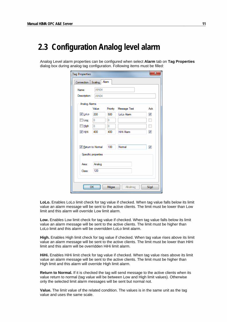
2.3 Configuration Analog level alarm Analog Level alarm properties can be configured when select Alarm tab on Tag Properties dialog box during analog tag configuration. Following items must be filled:
LoLo. Enables LoLo limit check for tag value if checked. When tag value falls below its limit value an alarm message will be sent to the active clients. The limit must be lower than Low limit and this alarm will override Low limit alarm. Low. Enables Low limit check for tag value if checked. When tag value falls below its limit value an alarm message will be sent to the active clients. The limit must be higher than LoLo limit and this alarm will be overridden LoLo limit alarm. High. Enables High limit check for tag value if checked. When tag value rises above its limit value an alarm message will be sent to the active clients. The limit must be lower than HiHi limit and this alarm will be overridden HiHi limit alarm. HiHi. Enables HiHi limit check for tag value if checked. When tag value rises above its limit value an alarm message will be sent to the active clients. The limit must be higher than High limit and this alarm will override High limit alarm. Return to Normal. If it is checked the tag will send message to the active clients when its value return to normal (tag value will be between Low and High limit values). Otherwise only the selected limit alarm messages will be sent but normal not. Value. The limit value of the related condition. The values is in the same unit as the tag value and uses the same scale.

Manual HIMA OPC A&E Server 12 Priority. Message severity values for limit alarm conditions and normal state. These values must be between 1 and 1000 according to the OPC specification. The lowest severity is 1 and the highest is 1000. Message Text. Additional message text for limit alarm conditions and normal state. The alarm condition and normal messages will be created from the description of tag and the related message text. Ack. If it is checked the message will require acknowledge from client.
Area and Class: Please, read the following!
Vendor specific (HIMA) event attributes Free user configurable Area: The attribute name is "Area". The value is free configurable for each event source. Type of the value is OLE string (VT_BSTR) Class: The attribute name is "Class". Type of the value is 4-byte-integer (VT_I4)
Auto populated
AREAS: Auto populated for each notification with the actual area. The actual area means the area provided by the existing auto area function. (VT_BSTR) NEW VALUE: The actual value of the belonging source at the time of the notification. (VT_VARIANT)

Manual HIMA OPC A&E Server 13
2.4 Configure User-defined alarm User-defined alarm properties can be configured, when Alarm tab on Tag Properties dia-log box during discrete (boolean) tag configuration is selected. This way user has a possi-bility to create a multi-state discrete alarm even, if the states come from the PES as inde-pendent binary signals. This multi-state group can be referenced in the OPC A&E client by a common name “Source” instead of individual tag names.
The binary alarm properties must be filled as in case of simple discrete alarms. However the selected binary alarm becomes one of the states of multi-state group. So it will be rep-resented as a condition and its subcondition. Any other tag can also be configured as same source to represent another condition and subcondition and so on. The names of conditions and subconditions are user-defined and described in the text file AE_COND.INI. This file should be placed in the A&E Server start directory (see example). This file is a hi-erarchical list of condition and subcondition names in the following structure: [Condition1 Name] Subcondition11 Name Subcondition12 Name ........ SubCondition1Last Name [Condition2 Name] Subcondition21 Name Subcondition22 Name ........ SubCondition2Last Name

Manual HIMA OPC A&E Server 14 Each row contains only one name. Condition name is the first between brackets and is fol-lowed by its subcondition names. This is repeated in the file. One condition is a multi-state alarm. It can be assigned to more than one alarm source and vice versa: One alarm source can have more than one condition and/or subcondition. Source. The name of the multi-state alarm object. If filled all the tags with same source name will behave as one alarm tag with different conditions and/or subconditions. Condition. Name of alarm condition. Comes from the INI file. Subcondition. Name of alarm subcondition. Also comes from INI file. Simple Condition. Attribute of the state. If checked this state is only low priority event, oth-erwise high priority alarm, which means the alarm becomes a “simple message”. Area and Class: Please, read the following!
Vendor specific (HIMA) event attributes Free user configurable Area: The attribute name is "Area". The value is free configurable for each event source. Type of the value is OLE string (VT_BSTR) Class: The attribute name is "Class". Type of the value is 4-byte-integer (VT_I4)
Auto populated
AREAS: Auto populated for each notification with the actual area. The actual area means the area provided by the existing auto area function. (VT_BSTR) NEW VALUE: The actual value of the belonging source at the time of the notification. (VT_VARIANT)
Manual HIMA OPC A&E Server 15
3. Menu items of HIMA OPC A&E Server
3.1 File menu
Contains usual file functions for opening, creating and saving tag configuration data files. It contains some possibilities for tag data conversion between this database and HIMA RES-Docu or CSV text data formats. This features are named imports and exports. Available menu items are:
New
Open
Save
Save As
Import HIMA RES Docu
Reimport HIMA RES Docu
Import CSV
Reimport CSV
Export CSV
Reexport CSV
Exit

Manual HIMA OPC A&E Server 16
3.1.1 File: New command Creates new empty configuration data without devices, groups and tags. The name of the new configuration always will be Untitled.
3.1.2 File: Open command Opens an existing configuration file. First the open dialog box will be displayed to select file name and the file extension. The HIMA OPC configuration datafile has always .HIM file ex-tension and saved in the Microsoft MFC 4.50 serialized format.
The configuration file contains the configuration data of defined ports, devices, groups and tags and their connection hierarchy.
The OPC server program automatically saves the last configuration name and loads the recently used configuration file during startup. It is very important when it was started by any client program using OLE/DCOM calls or by NT Service Control Manager.
The current configuration file only can be changed when no client connected to the OPC server parts. However the tag database (mostly the tags which are not in use) can be ed-ited manually on-line. Be careful editing tags which are in use by any client program. It is suggested avoiding this situation.
3.1.3 File: Save command Saves the current configuration data into the .HIM configuration file lastly loaded. The cur-rent configuration name is shown on the caption of main application window. If the current configuration file is Untitled the application will show the Save As dialog box to rename the configuration to an another name instead of this reserved name.
Save function can be performed in any time it does not disturb the data monitoring or re-fresh functions..
3.1.4 File: Save As command Saves the current configuration data on a new name. The new configuration file name and its extension can be selected from a dialog box named Save As. Default extension is the .HIM. Confirming new selection the data will be saved in a new name in Microsoft MFC 4.50 serialized format and the new configuration name will appear on the main application window’s caption.
Manual HIMA OPC A&E Server 17
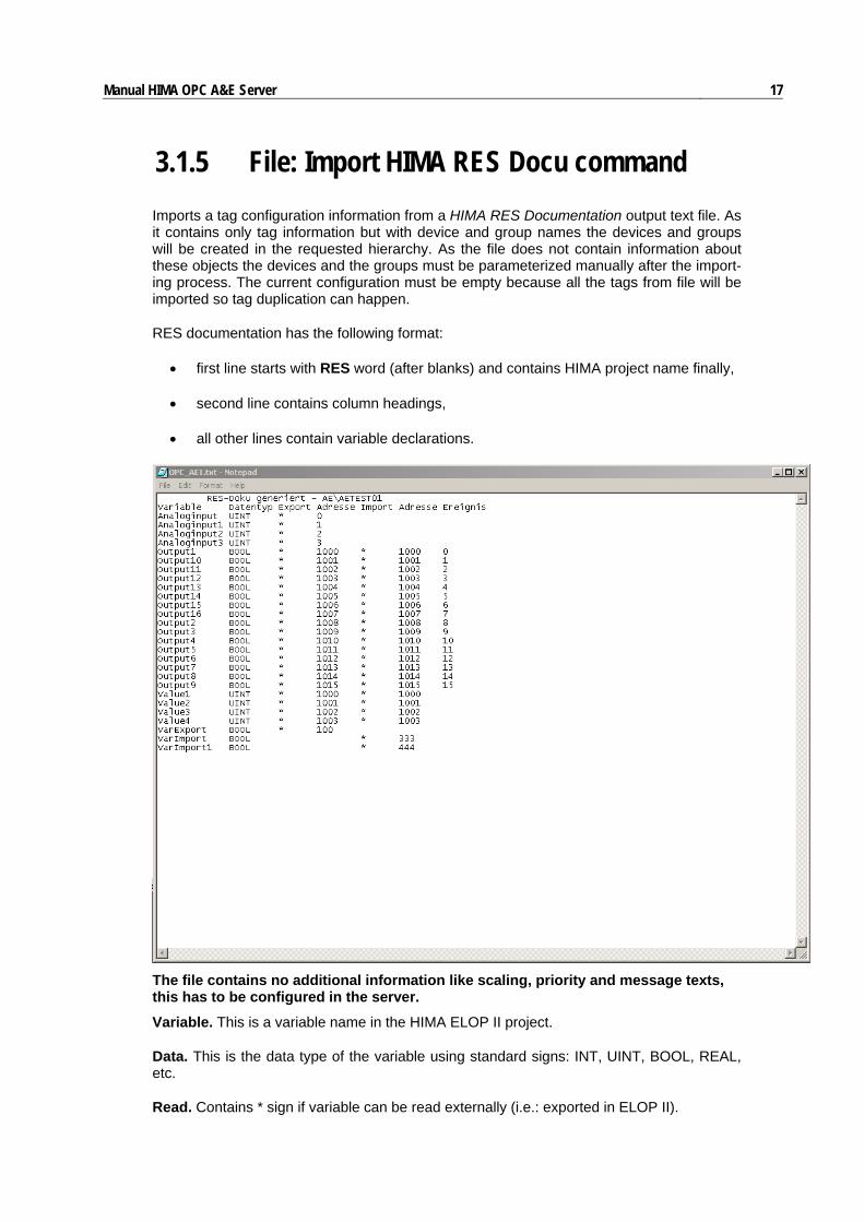
3.1.5 File: Import HIMA RES Docu command Imports a tag configuration information from a HIMA RES Documentation output text file. As it contains only tag information but with device and group names the devices and groups will be created in the requested hierarchy. As the file does not contain information about these objects the devices and the groups must be parameterized manually after the import-ing process. The current configuration must be empty because all the tags from file will be imported so tag duplication can happen.
RES documentation has the following format:
• first line starts with RES word (after blanks) and contains HIMA project name finally,
• second line contains column headings,
• all other lines contain variable declarations.
The file contains no additional information like scaling, priority and message texts, this has to be configured in the server.
Variable. This is a variable name in the HIMA ELOP II project.
Data. This is the data type of the variable using standard signs: INT, UINT, BOOL, REAL, etc.
Read. Contains * sign if variable can be read externally (i.e.: exported in ELOP II).

Manual HIMA OPC A&E Server 18 Address. This is Modbus export address of variable in ELOP II. Address can start from off-set 0.
Write. Contains * sign if variable can be write externally (i.e.: imported in ELOP II).
Address. This is Modbus import address of variable in ELOP II. Address can start from off-set 0.
Event. Event index from 0, if event has been defined for the variable in ELOP II. Variable must be BOOL type.
During import the program creates one device from one RES Docu. Device name will be the HIMA project name in RES Docu. Tags will be connected to two intermediate groups named Events and Tags. Tag which has read and/or write property will be connected to Tags. Tag, which has event property will be connected to Events. Tag, which has both properties will be created both in Tags and in Events group by same name. Write property can appear only together with read using the same address. So you should define variables in HIMA as export or export/import.
Scaling and alarm properties of normal tags must be manually filled. The event tags auto-matically will be generated providing Discrete Trip alarms with pre-defined severity and message text.
3.1.6 File: Reimport HIMA RES Docu command Reimports the previously imported HIMA RES Documentation output file again to update changes. Only the tags not existing will be created and added to the current configuration. The tags deleted from the RES Docu file will be kept in the configuration.
3.1.7 File: Import CSV File command Imports a tag configuration information from a CSV (comma delimited) text file. As it con-tains tag information with device and group names the devices and groups will be created in the requested hierarchy. As the file does not contain information about these objects the devices and the groups must be parameterized manually after the importing process. The current configuration must be empty because all the tags from file will be imported so tag duplication can happen.
The CSV file will contain all properties of tags as columns (without column header) in the following order in case of analog tag:
Name, Description, Data type, Location, Access, InitValue, Conversion, RawMin, RawMax, EngMin, EngMax, Unit, Normal Prty, Normal Text, LoLo Alarm Value, LoLo Alarm Prty, LoLo Alarm Text, Low Alarm Value, Low Alarm Prty, Low Alarm Text, High Alarm Value, High Alarm Prty, High Alarm Text, HiHi Alarm Value, HiHi Alarm Prty, HiHi Alarm Text, Simulation type, Source, Condition, Subcondition, Attribute, Process Low Value, Process High Value, Default Display, Normal Ack, LoLo Alarm Ack, Low Alarm Ack, High Alarm Ack, HiHi Alarm Ack. This will be the header line of the CSV file, too.

Manual HIMA OPC A&E Server 19 The CSV file will contain all properties of tags as columns (without column header) in the following order in case of discrete tag (not used are empty):
Name, Description, Data type, Location, Access, InitValue, Conversion, RawMin, RawMax, , , , , , Normal Prty, Normal Text, Disc. Alarm Value, Disc. Alarm Prty, Disc. Alarm Text, , , , , , , , , , Simulation type, Default Display, Source, Condition, Subcon-dition, Attribute, , Default Display, Normal Ack, Disc. Alarm Ack.
Name. This is the qualified name which starts with device name contains the group names in hierarchy and finishes with the tag name. The names are connected with dot (.) signal. Description. Tag description text. This will be the beginning part of alarm messages. It cannot contain CSV delimiter (comma) character. Data type. One of BOOL, INT, LONG, UINT, ULONG, REAL. Location. Modbus location string. Event stack signals uses E as data type. Access. Contains access right for tag: RO means read-ony, WO means write-only and RW means read write Conversion. LIN or SQR for analog, INV for binary. Empty or anything else means not used. Alarm Value. Numeric value on analog and 1 or 0 on discrete. If any alarm not used the field of Alarm type or related Alarm Value must be empty. Simulation type. SIN, RAMP or RANDOM. If not used it must e empty. Source. User-defined alarm source name. Because user-defined alarms are multi-state digital alarms more than one tag can have the same source property. Condition. Name of user-defined condition. Subcondition. Name of user-defined subcondition. Attribute. User-defined alarms have one attribute value: a boolean value to show whether the alarm is simple event or critical alarm. This value must be configured by user. Default Display. Default display name string. It could be used for DCS systems. They can retrive this value as OPC data tag property (see earlier). Alarm Ack. These fields will control whether any kind of alarms needs acknowledge from client system or not.
3.1.8 File: Reimport CSV File command Reimports the previously imported CSV text file again to update changes. Only the tags not existing will be created and added to the current configuration. The tags deleted from CSV file will be kept in the configuration.

Manual HIMA OPC A&E Server 20
3.1.9 File: Export CSV File command Exports the current tag configuration to a CSV (comma delimited) text file. Only the tags will be exported with its full name (including device and group name hierarchy) and properties. The property fields are delimited by comma characters. The output always overwrites the existing CSV file.
The structure and the order of columns in the CSV file will be in the same as described at Import CSV function.
3.1.10 File: Reexport CSV File command Reexports the currently loaded configuration into the recently used CSV file. The output will be appended to the existing CSV file so tag duplication can be happened. The tags deleted from configuration but existing in the CSV file will remain valid in the CSV.
3.1.11 File: Exit command Gives a possibility to exit the OPC Server application. Before exiting the save of the last configuration changes must be confirmed. If there is an active OPC client connected to the server a warning message will appear to avoid the illegal disconnection, which can cause a general OLE/COM failure.

Manual HIMA OPC A&E Server 21
3.2 Add menu Contains usual functions for creating new OPC objects as devices, groups and finally tags. Here is a possibility to create new tags automatically from existing tags name multiplying. Existing menu items are: New Device New Group New Tag Multiply

Manual HIMA OPC A&E Server 22
3.2.1 Add: New Device command Creates a new device and calls the Device Properties dialog box to define its properties. The device must have a unique name, all other parameters can be filled freely. After closing dialog box the defined device will appear in the tree view window between the devices. Fol-lowing properties must be filled:
Name. The identifier of device. All tagnames of this device will begin with this name as a root. Description. Long description of device. Device Type. One of HIMA device types H41/51q and PLANAR 4 can be selected. Event area. HIMA internal event area can be selected. Initially read event status. It defines whether server should read the real status of HIMA events during startup. If it is not checked these events will show their predefined initial value (configured on Scaling tab of Tag Property dialog). The real state will be shown on the first state change in PES.
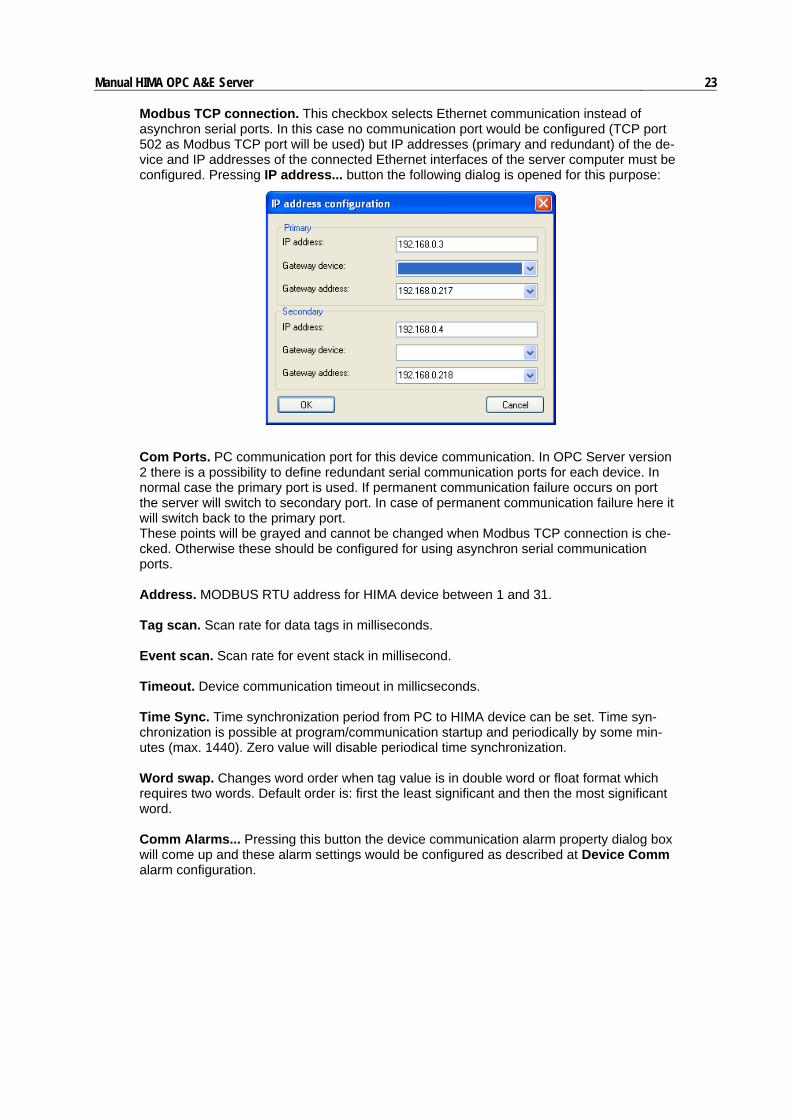
Manual HIMA OPC A&E Server 23 Modbus TCP connection. This checkbox selects Ethernet communication instead of asynchron serial ports. In this case no communication port would be configured (TCP port 502 as Modbus TCP port will be used) but IP addresses (primary and redundant) of the de-vice and IP addresses of the connected Ethernet interfaces of the server computer must be configured. Pressing IP address... button the following dialog is opened for this purpose:
Com Ports. PC communication port for this device communication. In OPC Server version 2 there is a possibility to define redundant serial communication ports for each device. In normal case the primary port is used. If permanent communication failure occurs on port the server will switch to secondary port. In case of permanent communication failure here it will switch back to the primary port. These points will be grayed and cannot be changed when Modbus TCP connection is che-cked. Otherwise these should be configured for using asynchron serial communication ports. Address. MODBUS RTU address for HIMA device between 1 and 31. Tag scan. Scan rate for data tags in milliseconds. Event scan. Scan rate for event stack in millisecond. Timeout. Device communication timeout in millicseconds. Time Sync. Time synchronization period from PC to HIMA device can be set. Time syn-chronization is possible at program/communication startup and periodically by some min-utes (max. 1440). Zero value will disable periodical time synchronization. Word swap. Changes word order when tag value is in double word or float format which requires two words. Default order is: first the least significant and then the most significant word. Comm Alarms... Pressing this button the device communication alarm property dialog box will come up and these alarm settings would be configured as described at Device Comm alarm configuration.
Manual HIMA OPC A&E Server 24
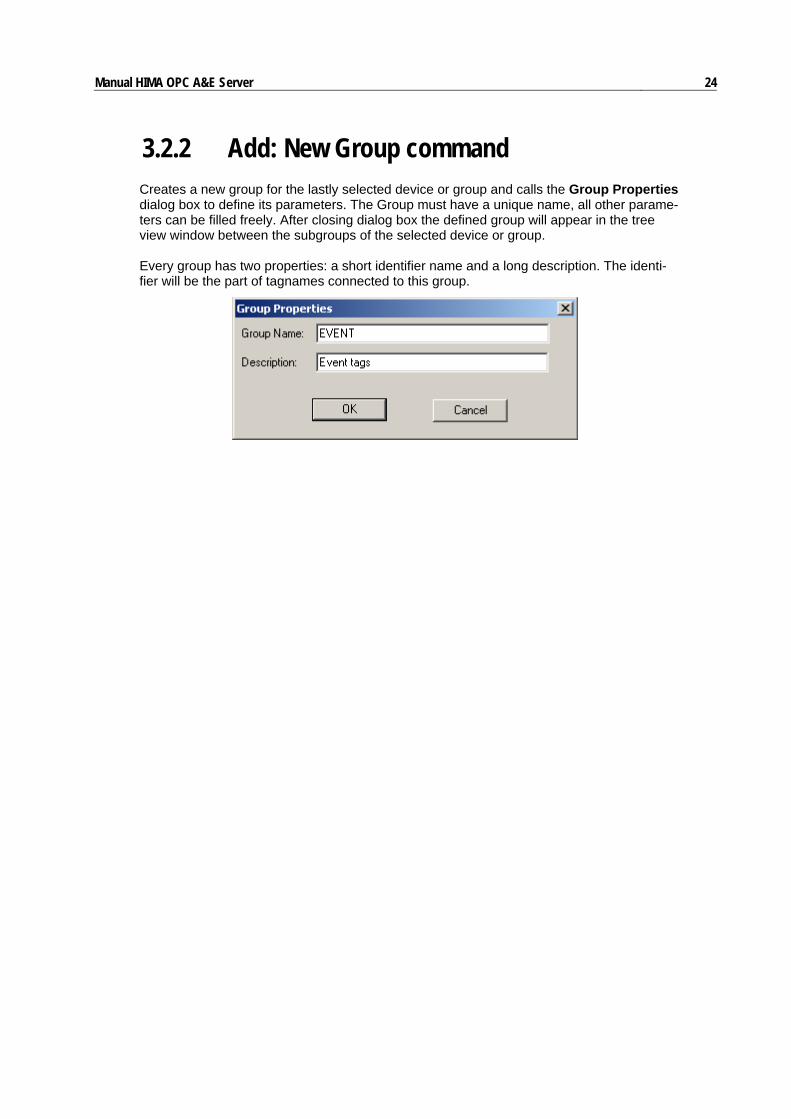
3.2.2 Add: New Group command Creates a new group for the lastly selected device or group and calls the Group Properties dialog box to define its parameters. The Group must have a unique name, all other parame-ters can be filled freely. After closing dialog box the defined group will appear in the tree view window between the subgroups of the selected device or group. Every group has two properties: a short identifier name and a long description. The identi-fier will be the part of tagnames connected to this group.

Manual HIMA OPC A&E Server 25
3.2.3 Add: New Tag command Creates a new tag for the lastly selected device or group and calls the Tag Properties dia-log box to define its parameters. The tag must have a unique name, all other parameters include the hardware connection location can be filled freely. After closing dialog box the defined tag will appear in the list view window and its device or group will be active on the tree view. The tag configuration dialog box contains three property pages: connection, scaling and alarm. The Connection property sheet contains the following properties:
Name. Short identified name of tag. This will be the final part of the qualified tagname string. Description. Long description text of the tag. Location. Over MODBUS location names: input status, output coil, input register or holding register the event signal type can also be selected. The location numbers always start from 1 according to the MODBUS general terminology. Data type. Raw data type in HIMA PES. For binary tags (input status, output coil or event signal) always BOOL will be shown automatically. Registers can be INT, UINT, LONG, ULONG or REAL data types. Number of Bytes. It shows the length of the data item in bytes. Cannot be edited. Def. Display. Default display name. It is a browsable property of this OPC DA tag. Simulation. Defines the simulation signal type: None, Sine, Ramp or Random. It will be used for generating tag values of simulated devices. Access rights. There is a possibility to manually control the access of variables. Read ac-cess can be configured for any Modbus data but write access only for Output coils and Holding Registers. For HIMA events the OPC A&E Server automatically generates read ac-cess, which cannot be changed by user.

Manual HIMA OPC A&E Server 26
3.2.4 Add: Multiply command The tags in the list view can be multiplied automatically if they have the continuous hard-ware connection location (for instance inputs or registers). The Multiply Tag dialog box will appear. The base name will defined using the lastly selected tag name. The base name will be extended with numbers with given decimal places (2 place enables maximum 100 tags, 3 place enables maximum 1000 tags, and so on). The first connection location also must be defined and it will be continuously increased by one location for each tag. Finally the num-ber of requested tags must be enter. Be careful, duplicated tag names cannot be generated but duplicated connections can hap-pened.
3.2.5 Add: Server Options command Several OPC Server working options can be set here. Some callback features, the trace file options and the redundancy options are adjustable. The settings are stored in the registry database under HKLM\Software\HIMA\HIMA A&E OPC Server key.
Manual HIMA OPC A&E Server 27
Enable changeless update. Enables “changeless update” feature: the DA server will re-fresh active points on every automatic refresh callback cycle even the points have not changed at all.
Enable short tag name in callbacks. Enables the AE server callbacks to contain only the real short tag names as “tag name”, not the qualified full path like Device-Name.GroupName.GroupName...TagName.
Trace file name. The name of the working trace file, which contains the trace information of OPC Server interfaces.
Trace file size. Maximum size of trace file. If the file overruns this limit during tracing it will be closed and renamed to name format YYYYMMDD.LOG. It is based on the current date: YYYY-current year, MM-current month (01-12), DD-current day (01-31) Then a new trace file will be automatically created with the configured trace file name.
If the file size is zero the trace file will grow up to the operating system or hard disk storage size limit.
The OPC Server version 2 supports the redundant OPC server feature The redundant server is also a HIMA A&E Server, running on a remote computer. Either of them must be time syn-chronization master. Redundant server support two features:
• time synchronization between server PCs, • synchronization of acknowledgement information.
Server redundancy is a computer level property. The related properties will be stored in the Windows registration database not in the configuration file. Following options must be filled:
Enable redundancy. Enables server redundancy feature.
Synchronization master. Either of PCs must be master and other must be slave. The real-time clock of PCs will be synchronized using the values of master Server clock.
Redundant Server. Name or IP address of redundant remote computer and the Gateway interface IP address which is used to route the redundant server when the server computer has more than one Ethernet interface installed.
Redundant servers are connected to each other using WinSock TCP/IP function on the specified TCP Port. In case of installed firewalls on the server-PCs, the TCP Port has to be released for full access.
Shutdown on disconnected. Presently not used.
Shutdown on comm. failure. If checked there will be a shutdown request sent to all client applications after the configured time (in seconds), when a complete communication failure (both communication channel failure for all devices) occurs. Client applications should re-lease the OPC server on this shutdown request so OPC server will quit.
Communication retry. Number of consecutive unsuccessful communication transactions after which the server will swap the active communication port to the secondary one and generate the communication redundancy failure alarm (if configured) and complete commu-nication failure alarm (if configured and the second interface is also in failure status.

Manual HIMA OPC A&E Server 28
3.3 Edit menu Contains usual functions for editing the existing object list. Here is a possibility for cutting, copying, pasting and deleting the selected objects as devices, groups or tags. A selected object can be also edited from here using Properties function. The serial communication port properties can be configured only here, too. Existing menu items are: Cut Copy Paste Delete Ports Properties

Manual HIMA OPC A&E Server 29
3.3.1 Edit: Cut command Cuts the currently selected object i.e. copies it into the clipboard and remove from its place. Only the single objects can be cut. If the object is a group or device its subgroups or tags will not be copied into the clipboard but will be deleted from the tree view.
3.3.2 Edit: Copy command Copies the currently selected object with its properties into the clipboard but will not remove it from its place. Only single objects can be copied. If the object is a group or device its subgroups or tags will not be copied together with their parent object.
3.3.3 Edit: Paste command Inserts the object, which previously had been cut or copied to the clipboard. The object can only be pasted between the same type objects as itself is. Otherwise nothing will be hap-pened.
3.3.4 Edit: Delete command Deletes the currently selected object(s) form the tree view or list view. If some tag(s) were selected they will be simply deleted form the list. If a device(s) or group(s) were selected all they will be deleted and with all objects contained by them.

Manual HIMA OPC A&E Server 30
3.3.5 Edit: Ports command Calls the Port Configuration dialog box to set the port parameters. COM1...COM16 ports can be adjusted. For each port the baud rate, parity, data and stop bits and the flow control can be set similarly the Windows port configuration dialog. The default values are the most probably used values in the practice.
The following properties must be filled:
Port ID. The currently selected port name as PC standard.
Baud Rate. Selected port baud rate. HIMA uses 9600 or 57600.
Parity. The selected port parity format can be specified. Default is even parity.
Flow Ctrl. The selected port flow control can be selected. HIMA usually does not uses hardware (RTS/CTS) flow control.
Data Bits. The selected port data length can be specified. MODBUS RTU protocol always uses 8 bit data format.
Stop Bits. The selected port stop length can be specified. 1 or 2 stop bits can be used.
3.3.6 Edit: Properties command The properties of the currently selected object in the tree view or list view can be edited. If a device is selected the Device Property dialog box will appear. If the group is selected the Group Property dialog box will appear. If a tag is selected on the list view the Tag Prop-erty dialog box will appear. This item will be shown in the local menu of the selected object, too.

Manual HIMA OPC A&E Server 31
3.4 View menu Contains usual functions for controlling the OPC views. The status bar and the monitoring function can be switched on or off. These states can be seen in the menu panel as a check at the item name. Menu items:
Monitor
Device Monitor
Server Statistics
Status Bar
Manual HIMA OPC A&E Server 32
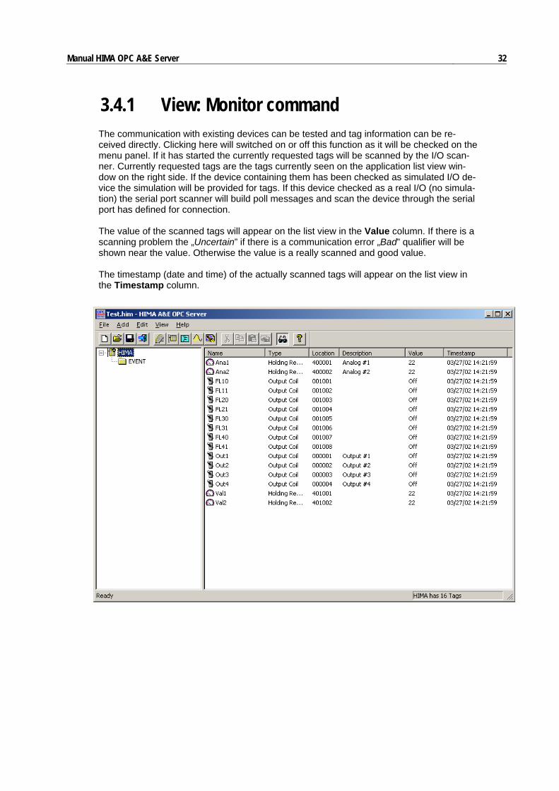
3.4.1 View: Monitor command The communication with existing devices can be tested and tag information can be re-ceived directly. Clicking here will switched on or off this function as it will be checked on the menu panel. If it has started the currently requested tags will be scanned by the I/O scan-ner. Currently requested tags are the tags currently seen on the application list view win-dow on the right side. If the device containing them has been checked as simulated I/O de-vice the simulation will be provided for tags. If this device checked as a real I/O (no simula-tion) the serial port scanner will build poll messages and scan the device through the serial port has defined for connection. The value of the scanned tags will appear on the list view in the Value column. If there is a scanning problem the „Uncertain” if there is a communication error „Bad” qualifier will be shown near the value. Otherwise the value is a really scanned and good value. The timestamp (date and time) of the actually scanned tags will appear on the list view in the Timestamp column.
Manual HIMA OPC A&E Server 33
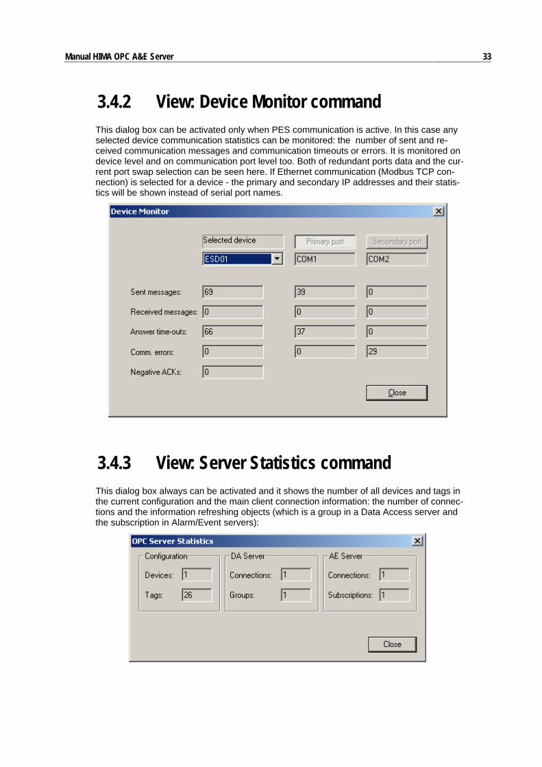
3.4.2 View: Device Monitor command This dialog box can be activated only when PES communication is active. In this case any selected device communication statistics can be monitored: the number of sent and re-ceived communication messages and communication timeouts or errors. It is monitored on device level and on communication port level too. Both of redundant ports data and the cur-rent port swap selection can be seen here. If Ethernet communication (Modbus TCP con-nection) is selected for a device - the primary and secondary IP addresses and their statis-tics will be shown instead of serial port names.
3.4.3 View: Server Statistics command This dialog box always can be activated and it shows the number of all devices and tags in the current configuration and the main client connection information: the number of connec-tions and the information refreshing objects (which is a group in a Data Access server and the subscription in Alarm/Event servers):

Manual HIMA OPC A&E Server 34
3.4.4 View: Status Bar command The existence of the status bar at the bottom of the main application window will be switched on or off. This means that it will be shown or hidden as it is checked on the menu panel. This status bar is used for displaying some information for current actions to help user.

Manual HIMA OPC A&E Server 35
3.5 Help menu Contains usual help possibilities regarding the OPC Server framework and the HIMA com-munication rules and device capabilities. The product about box can be called out also from here. Existing menu items are:
English Content
German Content
About HIMA A&E OPC Server

Manual HIMA OPC A&E Server 36
3.5.1 Help: English Content command The WinHelp-style help file in English language can be activated and displayed from here. The default name of the English Help file is HIMAOPC_E.HLP. This file must be in the home directory of the HIMA OPC Server (default installation path is: Program Files\HIMA\OPC_AE).
3.5.2 Help: German Content command The WinHelp-style help file in German language can be activated and displayed from here. The default name of the German Help file is HIMAOPC_D.HLP. This file must be in the home directory of the HIMA OPC Server (default installation path is: Program Files\HIMA\OPC_AE).
3.5.3 Help: About HIMA A&E OPC Server The program About box can be displayed here as shown:
The About box contains program name, version and the license information items: user name, company name and current program serial number used during installation. Edition: Version 1.2 (1040)