Highway Embankments in Ohio: Soil Properties and … STGEC - Highway... · Highway Embankments in...
89
Highway Embankments in Ohio: Soil Properties and Slope Stability Terry Masada, Ph.D. Professor & Assistant Chair Civil Engineering Department Ohio University, Athens, OH STGEC 2010 October 5, 2010 Charleston, West Virginia
Transcript of Highway Embankments in Ohio: Soil Properties and … STGEC - Highway... · Highway Embankments in...
Highway Embankments
in Ohio: Soil Properties
and Slope Stability
Terry Masada, Ph.D.
Professor & Assistant Chair
Civil Engineering Department
Ohio University, Athens, OH
STGEC 2010October 5, 2010
Charleston, West Virginia

2Ohio University - Ohio Research Institute for Transportation and the Environment
Background
• Roadway embankments constitute one of the most common geotechnical facilities in the U.S.
• Despite its seemingly straightforward nature, design and construction of highway embankments are complicated by the fact that a number of key issues (bearing capacity, settlement, drainage, erosion, and slope stability) must be all taken care of.
• In Ohio, highway embankments have been designed often using soil properties that are based on previously published default values or that are derived from empirical correlations found in literature.
• This practice has become popular, since it reduces project cost and time.

3Ohio University - Ohio Research Institute for Transportation and the Environment
Background
• Main problem with soil property data found in the
literature is that it was in most cases determined
for soils found outside Ohio and in some cases
outside the U.S. Applicability of the literature data
to Ohio soils has not been fully investigated.
• Because of the popular short-cut approach, there
have been some cases in Ohio where
embankment slopes suffered slope instability
problems.
• Structural stability of roadway embankments is vital
to the state economy and public safety.

4Ohio University - Ohio Research Institute for Transportation and the Environment
Background
• The geotechnical research team at Ohio University
recently conducted a comprehensive study on
shear strength properties of soils and stability of
highway embankments for the Ohio Department of
Transportation.
5Ohio University - Ohio Research Institute for Transportation and the Environment
Project Tasks
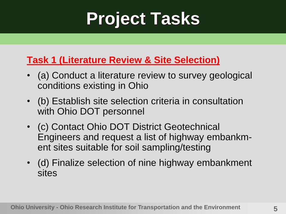
Task 1 (Literature Review & Site Selection)
• (a) Conduct a literature review to survey geological conditions existing in Ohio
• (b) Establish site selection criteria in consultation with Ohio DOT personnel
• (c) Contact Ohio DOT District Geotechnical Engineers and request a list of highway embankm-ent sites suitable for soil sampling/testing
• (d) Finalize selection of nine highway embankment sites

6Ohio University - Ohio Research Institute for Transportation and the Environment
Project Tasks
Task 2 (Field & Laboratory Soil Testing)
• (a) Calibrate equipment that will be used in the field
• (b) Perform subsurface exploration work at each
highway embankment site
• (c) Subject soil samples recovered from the sites to
index property and shear strength tests in the
laboratory
• (d) Analyze all laboratory test data
7Ohio University - Ohio Research Institute for Transportation and the Environment
Project Tasks
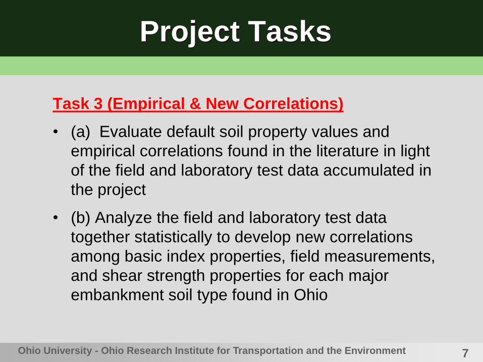
Task 3 (Empirical & New Correlations)
• (a) Evaluate default soil property values and
empirical correlations found in the literature in light
of the field and laboratory test data accumulated in
the project
• (b) Analyze the field and laboratory test data
together statistically to develop new correlations
among basic index properties, field measurements,
and shear strength properties for each major
embankment soil type found in Ohio

8Ohio University - Ohio Research Institute for Transportation and the Environment
Project Tasks
Task 4 (Slope Stability Analysis & Guidelines)
• (a) Feed the average properties of each major soil
type encountered into a series of computerized
embankment slope stability analysis
• (b) Formulate a set of guidelines concerning both
the design and construction of highway
embankment structures in Ohio
9Ohio University - Ohio Research Institute for Transportation and the Environment
Task 1
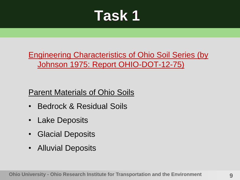
Engineering Characteristics of Ohio Soil Series (by
Johnson 1975: Report OHIO-DOT-12-75)
Parent Materials of Ohio Soils
• Bedrock & Residual Soils
• Lake Deposits
• Glacial Deposits
• Alluvial Deposits

10
Task 1
Ohio University - Ohio Research Institute for Transportation and the Environment
Western Ohio
Limestone
& Shale
Eastern Ohio
Sandstone
& Shale
Division
Line
Bedrocks in Ohio
11Ohio University - Ohio Research Institute for Transportation and the Environment
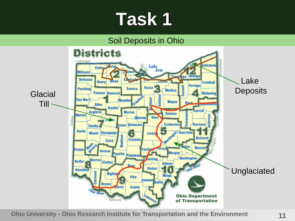
Task 1Soil Deposits in Ohio
Lake
Deposits
Unglaciated
Glacial
Till

12Ohio University - Ohio Research Institute for Transportation and the Environment
Task 1
Site Selection Criteria
• Embankment fill height over 25 ft (7.6 m)
• Embankment soil fill cohesive
• Site located on major highway
• Site recommended by ODOT or subcontractor
• Site represents unique geographical location or geological condition not duplicated many times previously
• Slopes at the site not experiencing any instability problems
• A lack of gravel size particles and rock fragments
• No guardrails
• Relatively level grassed area in median or beyond shoulder
• Age was determined to be a nonfactor
13
Task 1
Ohio University - Ohio Research Institute for Transportation and the Environment
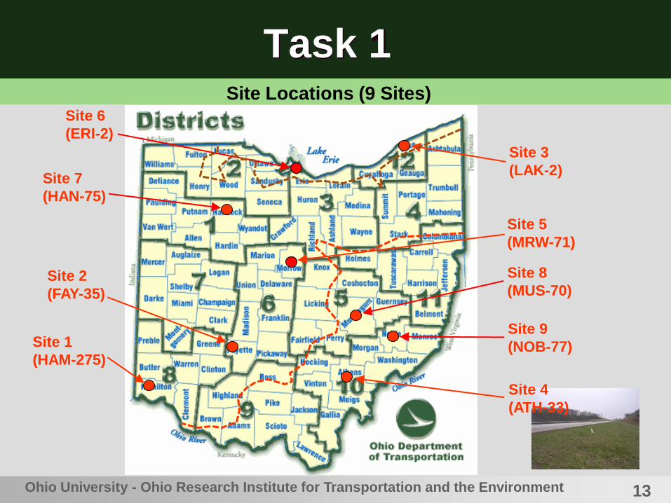
Site 1
(HAM-275)
Site 2
(FAY-35)
Site 3
(LAK-2)
Site 5
(MRW-71)
Site 6
(ERI-2)
Site 7
(HAN-75)
Site 8
(MUS-70)
Site 9
(NOB-77)
Site 4
(ATH-33)
Site Locations (9 Sites)

14Ohio University - Ohio Research Institute for Transportation and the Environment
Task 1
Distributions of Selected Field Sites
• Three (3) sites in northern Ohio
• Four (4) sites in central Ohio
• Three (2) sites in southern Ohio
• Seven (7) ODOT districts
• Two (2) sites (east, west) in the lake deposits area
• Four (4) sites in the glaciated region
• Four (3) sites in the unglaciated region

15Ohio University - Ohio Research Institute for Transportation and the Environment
Task 2
Standard Penetration Test (SPT)
• Oldest and most commonly used in-situ soil test
method
• Drop a 140-lb (64-kg) hammer 30 inches (0.76 m)
to drive a split-spoon barrel
• SPT-N value = number of hammer blows per 1-ft
(0.3-m) penetration
• SPT-N value depends on several factors such as
the hammer type, actual drop height, inclination of
the hole, hole diameter, presence of liner inside
split-spoon barrel, and test depth.
16Ohio University - Ohio Research Institute for Transportation and the Environment
Task 2
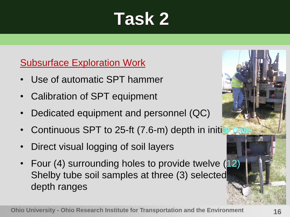
Subsurface Exploration Work
• Use of automatic SPT hammer
• Calibration of SPT equipment
• Dedicated equipment and personnel (QC)
• Continuous SPT to 25-ft (7.6-m) depth in initial hole
• Direct visual logging of soil layers
• Four (4) surrounding holes to provide twelve (12)
Shelby tube soil samples at three (3) selected
depth ranges

17Ohio University - Ohio Research Institute for Transportation and the Environment
Task 2
SPT Automatic Hammer Calibration
• Maximum Energy Transferred to Rods (EMX):
where F(t) = force measured at time t; and V (t) = velocity
measured at time t.
• Energy transfer ratio (ETR) = EMX/(Theoretical SPT Hammer
Energy) = EMX/(0.35 kip-ft)
• Calibration by GRL Engineering, Inc. (Cleveland, OH; Tel. 216-
292-3076); depth 1 to 25.5 ft
• Results: ETR = 78.8 to 84.4% (ave. 81.6%) for Truck #55 with
CME automatic hammer & AWJ rods.
dttVtFEMX )(PAK model pile
driver analyzer

18Ohio University - Ohio Research Institute for Transportation and the Environment
Task 2
Normalization of SPT-N value
• SPT-N values are normalized to an overburden pressure of 1
tsf (13.9 psi, 95.7 kPa) and to an energy transfer rate of 60%
(= energy typically applied by the safety hammer in the U.S.)
(N1)60 = CN * N60 = CN * (ETR/60) * N
where (N1)60 = fully normalized SPT N value; CN = depth or over-
burden pressure correction factor; N60 = N value measured with 60
% hammer efficiency; ETR = energy transfer ratio (%); and N = raw
N value.
19Ohio University - Ohio Research Institute for Transportation and the Environment
Task 2
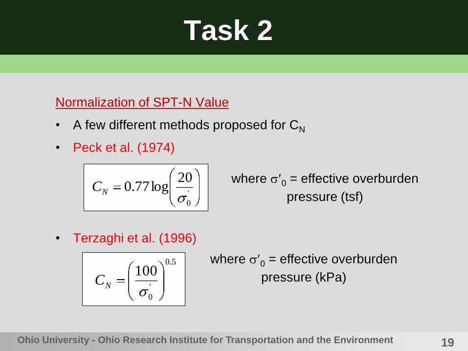
Normalization of SPT-N Value
• A few different methods proposed for CN
• Peck et al. (1974)
• Terzaghi et al. (1996)
'
0
20log77.0NC
where 0 = effective overburden
pressure (tsf)
5.0
'
0
100NC
where 0 = effective overburden
pressure (kPa)

20Ohio University - Ohio Research Institute for Transportation and the Environment
Task 2
Normalization of SPT-N Values
• Seed et al. (1975)
• Skempton (1986)
a
Np
C'
0log25.11
a
Np
C/1
2'
0
where 0 = effective overburden
pressure (psf); and pa = atmos-
pheric pressure (= 2,000 psf = 1
tsf)

21
Task 2
• Apply the approach proposed by Seed et al. (1975)
to normalize N60 values, as it represented the
average of all the CN values.
• Determine the three soil sampling depths by
selecting high, medium, and low (N60)1 values.
• High (N60)1 value should be below 40 to prevent
Shelby tube from crushing.
• If soil type changes through depth, place at least
one sampling depth within each soil type.
Ohio University - Ohio Research Institute for Transportation and the Environment
22Ohio University - Ohio Research Institute for Transportation and the Environment
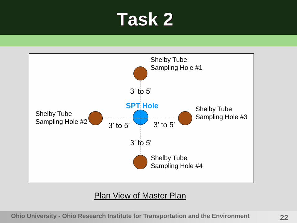
Task 2
SPT Hole
Shelby Tube
Sampling Hole #1
Shelby Tube
Sampling Hole #2
Shelby Tube
Sampling Hole #3
Shelby Tube
Sampling Hole #4
Plan View of Master Plan
3’ to 5’3’ to 5’
3’ to 5’
3’ to 5’

23Ohio University - Ohio Research Institute for Transportation and the Environment
Task 2
Side View of Master Plan
SPT Hole G.S.
Depth Range #1
Depth Range #2
Depth Range #325’ o
f E
mbankm
ent
Fill
3’ to 5’ 3’ to 5’
(N60)1
Shelby Tube HoleShelby Tube Hole
Low
Med.
High

24
Task 2
• AASHTO Soil Classification System
A-4 A-5 A-6 A-7-6
(-) No. 200 36 min.
Liquid Limit (LL) 40 max. 41 min. 40 max. 41 min.
Plasticity Index (PI) 10 max. 11 min.
Description Silty soils Clayey soils
Note PI > (LL-30)
[Note] Max. dry unit weight (typical) = 120 pcf for A-4 soils; 110 pcf for A-6 &
A-7-6 soils --- Ref. ODOT (2006), “Construction Inspection Manual of
Procedures,” Columbus, OH, pp. 962-963.
25
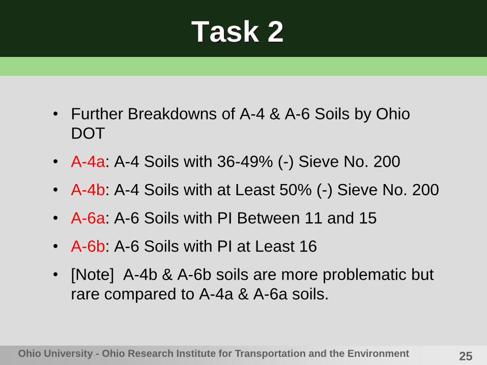
Task 2
• Further Breakdowns of A-4 & A-6 Soils by Ohio
DOT
• A-4a: A-4 Soils with 36-49% (-) Sieve No. 200
• A-4b: A-4 Soils with at Least 50% (-) Sieve No. 200
• A-6a: A-6 Soils with PI Between 11 and 15
• A-6b: A-6 Soils with PI at Least 16
• [Note] A-4b & A-6b soils are more problematic but
rare compared to A-4a & A-6a soils.
Ohio University - Ohio Research Institute for Transportation and the Environment

26Ohio University - Ohio Research Institute for Transportation and the Environment
Task 2
List of Fundamental Laboratory Tests
• Visual soil descriptions
• Moisture contents & Dry unit weight
• Atterberg limits (plastic; liquid plasticity index)
• Grain size analysis (mechanical sieve; hydrometer)
• Soil classifications by AASHTO/ODOT method
• Specific gravity
• Unconfined compression strength
27Ohio University - Ohio Research Institute for Transportation and the Environment
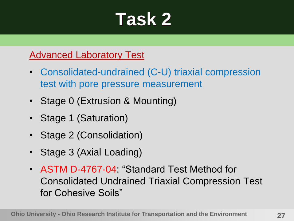
Task 2
Advanced Laboratory Test
• Consolidated-undrained (C-U) triaxial compression
test with pore pressure measurement
• Stage 0 (Extrusion & Mounting)
• Stage 1 (Saturation)
• Stage 2 (Consolidation)
• Stage 3 (Axial Loading)
• ASTM D-4767-04: “Standard Test Method for
Consolidated Undrained Triaxial Compression Test
for Cohesive Soils”
28Ohio University - Ohio Research Institute for Transportation and the Environment
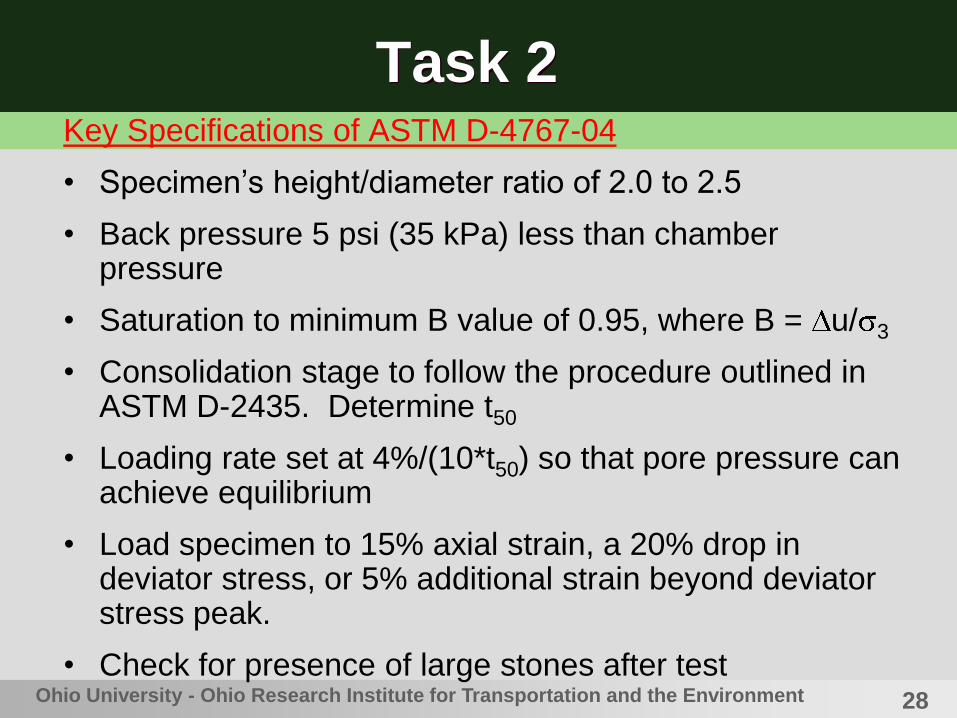
Task 2Key Specifications of ASTM D-4767-04
• Specimen’s height/diameter ratio of 2.0 to 2.5
• Back pressure 5 psi (35 kPa) less than chamber pressure
• Saturation to minimum B value of 0.95, where B = u/ 3
• Consolidation stage to follow the procedure outlined in ASTM D-2435. Determine t50
• Loading rate set at 4%/(10*t50) so that pore pressure can achieve equilibrium
• Load specimen to 15% axial strain, a 20% drop in deviator stress, or 5% additional strain beyond deviator stress peak.
• Check for presence of large stones after test

29Ohio University - Ohio Research Institute for Transportation and the Environment
Task 2
d
3
Soil specimen encased
in rubber membraneChamber confining
pressure applied
through water
Drainage line
w/ pressure
transducer
Loading piston equipped
w/ load cell
Axial deformation
censor
Components of Triaxial Test Set-Up
30Ohio University - Ohio Research Institute for Transportation and the Environment
Task 2
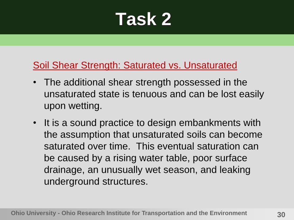
Soil Shear Strength: Saturated vs. Unsaturated
• The additional shear strength possessed in the
unsaturated state is tenuous and can be lost easily
upon wetting.
• It is a sound practice to design embankments with
the assumption that unsaturated soils can become
saturated over time. This eventual saturation can
be caused by a rising water table, poor surface
drainage, an unusually wet season, and leaking
underground structures.

31Ohio University - Ohio Research Institute for Transportation and the Environment
Task 2
• Shear Strength Parameters
• Internal Friction Angle ( ; ) describes the frictional
properties of individual particles and interlocking
between particles. It is known to depend on soil
mineral type, gradation, soil particle shape, and
void ratio.
• Cohesion (c; c ) describes the bonding between
soil particles due to cementation, electrostatic
attractions, and covalent bonding.
32
Task 2
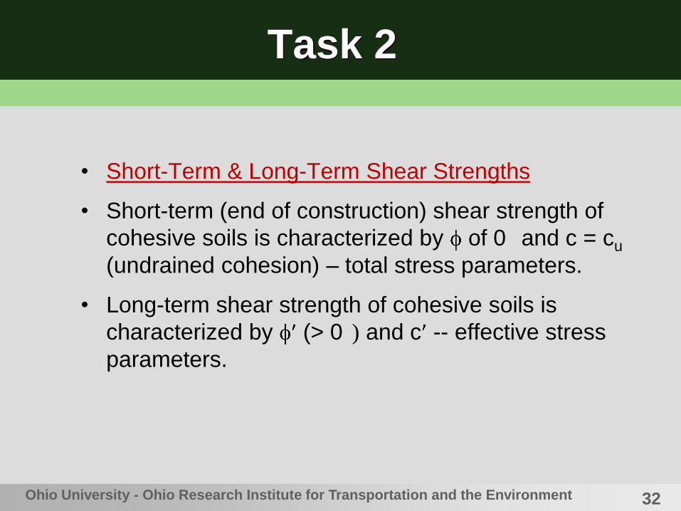
• Short-Term & Long-Term Shear Strengths
• Short-term (end of construction) shear strength of
cohesive soils is characterized by of 0 and c = cu
(undrained cohesion) – total stress parameters.
• Long-term shear strength of cohesive soils is
characterized by (> 0 ) and c -- effective stress
parameters.
Ohio University - Ohio Research Institute for Transportation and the Environment

33Ohio University - Ohio Research Institute for Transportation and the Environment
Task 2
Laboratory Determination of Soil Shear Strength
• Perform triaxial tests at three confining pressure levels
• Minimum confining pressure needs to be larger than over-burden pressure to assure normally consolidated soil behaviors
• Plot the results from three tests in p-q and p -q diagrams, where p = ( 1f + 3)/2; q = ( 1f - 3)/2;
p = ( 1f + 3)/2; and
q = ( 1f - 3)/2Stress path method
34
Task 2
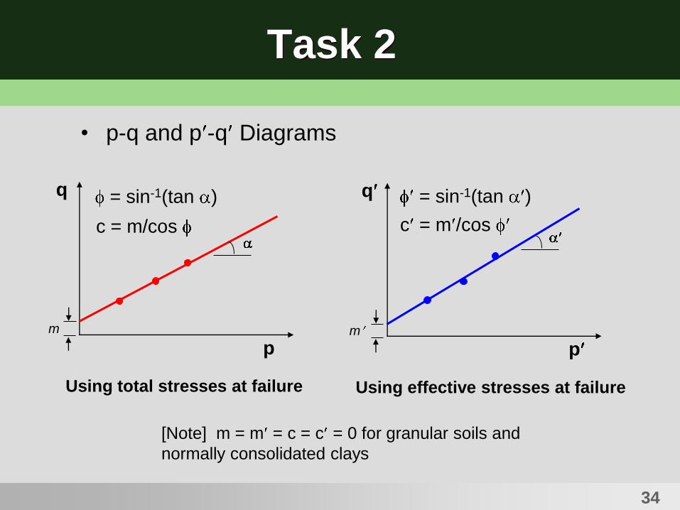
• p-q and p -q Diagrams
q
p
q
p
Using total stresses at failure Using effective stresses at failure
= sin-1(tan ) = sin-1(tan )
m
c = m/cos
m
c = m /cos
[Note] m = m = c = c = 0 for granular soils and
normally consolidated clays

35Ohio University - Ohio Research Institute for Transportation and the Environment
Task 2
Unconfined Compression Test
• Performed only on cohesive soils
• Rapid test to obtain undrained cohesion strength
(cu):
cu = 1/2
• Considered as a special case of U-U test
• Involves no confining pressure;
• No drainage

36Ohio University - Ohio Research Institute for Transportation and the Environment
Task 2Field Test Data from Site 7 (HAN-75) – March 28, 2008
• I-75, Approx. 0.5 miles north of Exit 142 (Bluffton exit)
• SPT hole placed in outside shoulder area of northbound lanes
Depth (ft) N Value (N60)1 Depth (ft) N Value (N60)1
1.0-2.5 19 74.8 13.0-14.5 12 17.3
2.5-4.0 13 37.8 14.5-16.0 25 34.5
4.0-5.5 14 34.0 16.0-17.5 17 22.6
5.5-7.0 16 34.1 17.5-19.0 33 42.2
7.0-8.5 15 28.7 19.0-20.5 10 12.3
8.5-10.0 23 40.2 20.5-22.0 21 25.0
10.0-11.5 9 14.6 22.0-23.5 21 24.3
11.5-13.0 20 30.2 23.5-25.0 25 35.8
[Notes] Ave. unit weight of soil = 130 pcf (assumed).
No groundwater table encountered.

37Ohio University - Ohio Research Institute for Transportation and the Environment
Task 2
• Shelby Tube Sampling at Site 7 (HAN-75)
Tube ID Depth (ft) Recovery (in)
A-1 5.5-7.0 18.0
A-2 10.0-11.3 15.6
A-3 16.0-17.8 21.6
B-2 10.0-11.9 22.8
B-3 16.0-17.8 21.6
C-1 5.5-7.3 21.6
C-3 16.0-18.0 24.0
D-1 5.5-6.9 16.8
D-2 10.0-11.4 16.8
D C
B
AN
[Note] Tube length = 36.0 inches.

38Ohio University - Ohio Research Institute for Transportation and the Environment
Task 2
Cutting of Shelby Tube into Shorter Sections
39Ohio University - Ohio Research Institute for Transportation and the Environment
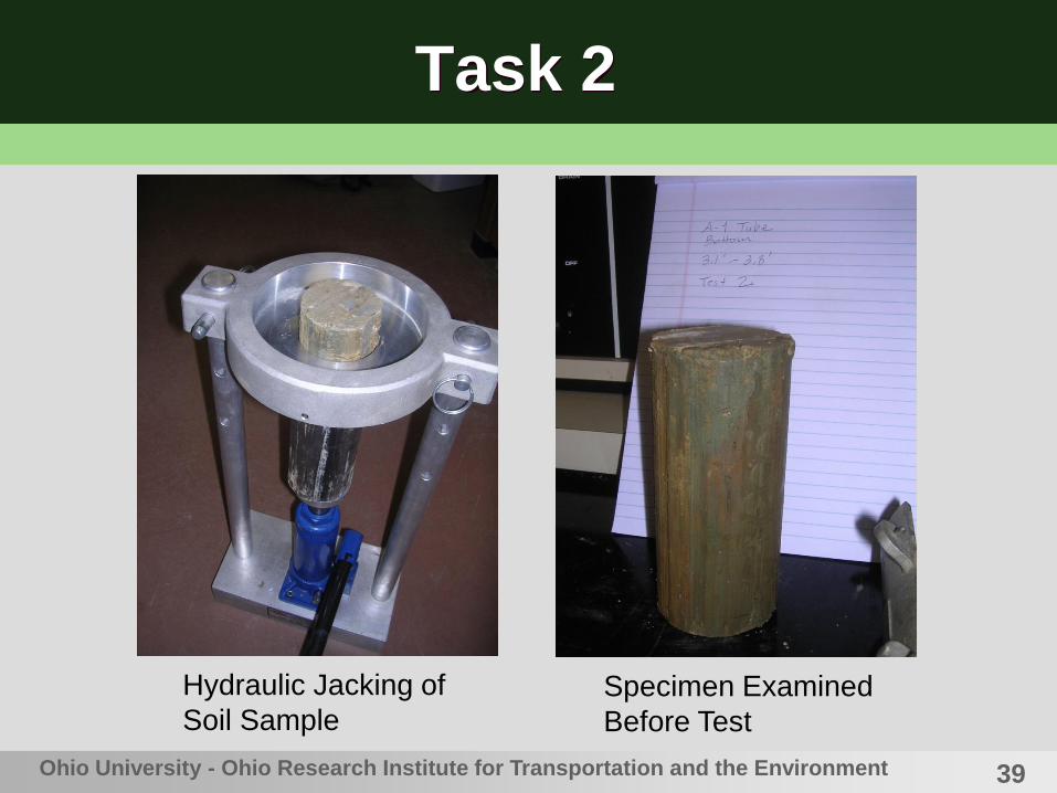
Task 2
Hydraulic Jacking of
Soil SampleSpecimen Examined
Before Test
40Ohio University - Ohio Research Institute for Transportation and the Environment
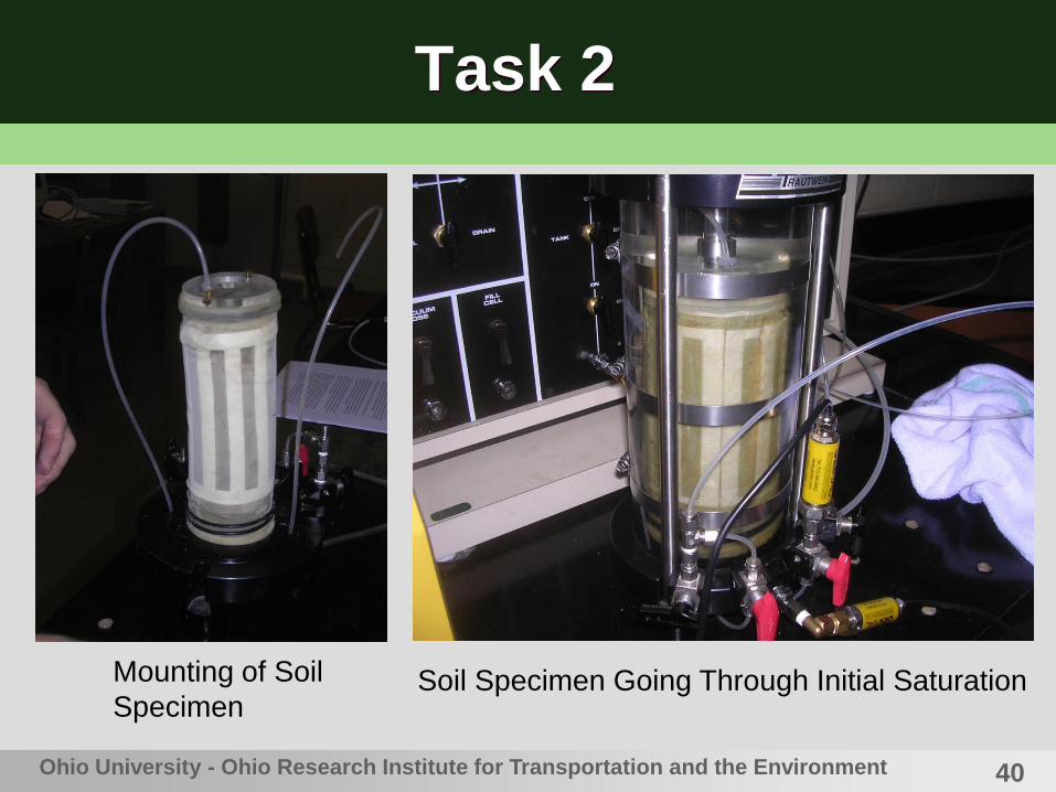
Task 2
Mounting of Soil
SpecimenSoil Specimen Going Through Initial Saturation

41Ohio University - Ohio Research Institute for Transportation and the Environment
Task 2
Triaxial Compression Test in Progress
Examination of Soil
Specimen After Test
(Specimens usually do not
exhibit clearly defined shear
failure planes.)
42Ohio University - Ohio Research Institute for Transportation and the Environment
Task 2
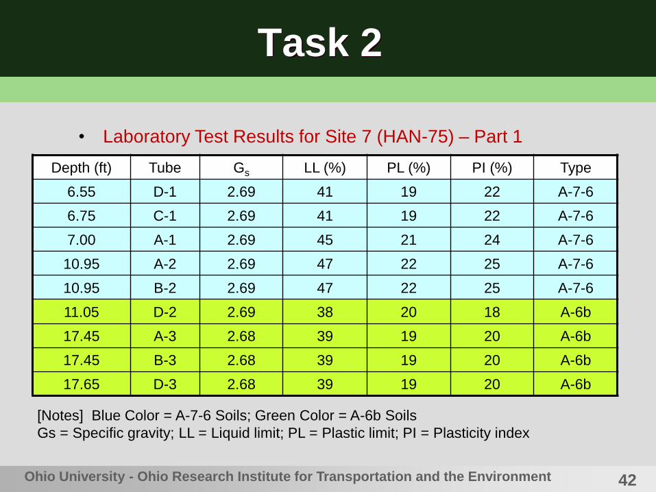
• Laboratory Test Results for Site 7 (HAN-75) – Part 1
Depth (ft) Tube Gs LL (%) PL (%) PI (%) Type
6.55 D-1 2.69 41 19 22 A-7-6
6.75 C-1 2.69 41 19 22 A-7-6
7.00 A-1 2.69 45 21 24 A-7-6
10.95 A-2 2.69 47 22 25 A-7-6
10.95 B-2 2.69 47 22 25 A-7-6
11.05 D-2 2.69 38 20 18 A-6b
17.45 A-3 2.68 39 19 20 A-6b
17.45 B-3 2.68 39 19 20 A-6b
17.65 D-3 2.68 39 19 20 A-6b
[Notes] Blue Color = A-7-6 Soils; Green Color = A-6b Soils
Gs = Specific gravity; LL = Liquid limit; PL = Plastic limit; PI = Plasticity index

43Ohio University - Ohio Research Institute for Transportation and the Environment
Task 2
• Laboratory Test Results for Site 7 (HAN-75) – Part 2
Depth (ft) Tube %G %S %M %C
6.55 D-1 2 19 32 46
6.75 C-1 2 19 32 46
7.00 A-1 3 16 33 48
10.95 A-2 1 16 32 50
10.95 B-2 1 16 32 50
11.05 D-2 1 19 36 44
17.45 A-3 3 17 34 47
17.45 B-3 3 17 34 47
17.65 D-3 3 17 34 47
[Notes] Blue Color = A-7-6 Soils; Green Color = A-6b Soils
%G = % Gravel; %S = % Sand; %M = % Silt; %C = % Clay

44Ohio University - Ohio Research Institute for Transportation and the Environment
Task 2
• Laboratory Test Results for Site 7 (HAN-75) – Part 3
Depth (ft) Tube w (%) d (pcf) qu (psi) (N60)1
6.55 D-1 20.0 110.1 24.6 34
6.75 C-1 20.0 110.1 24.6 34
7.00 A-1 21.4 107.2 39.4 34
10.95 A-2 21.4 107.2 39.4 15
10.95 B-2 21.6 105.1 34.4 15
11.05 D-2 20.1 108.8 35.9 30
17.45 A-3 18.5 111.3 61.2 23
17.45 B-3 18.5 111.3 61.2 42
17.65 D-3 18.5 111.3 61.2 42
[Notes] Blue Color = A-7-6 Soils; Green Color = A-6b Soils
w = Moisture content; d = Dry unit weight; qu = Unconfined compr. strength
45Ohio University - Ohio Research Institute for Transportation and the Environment
Task 2
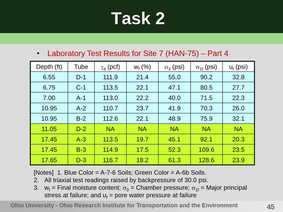
• Laboratory Test Results for Site 7 (HAN-75) – Part 4
Depth (ft) Tube d (pcf) wf (%) 3 (psi) 1f (psi) uf (psi)
6.55 D-1 111.9 21.4 55.0 90.2 32.8
6.75 C-1 113.5 22.1 47.1 80.5 27.7
7.00 A-1 113.0 22.2 40.0 71.5 22.3
10.95 A-2 110.7 23.7 41.9 70.3 26.0
10.95 B-2 112.6 22.1 48.9 75.9 32.1
11.05 D-2 NA NA NA NA NA
17.45 A-3 113.5 19.7 45.1 92.1 20.3
17.45 B-3 114.9 17.5 52.3 109.6 23.5
17.65 D-3 116.7 18.2 61.3 128.6 23.9
[Notes] 1. Blue Color = A-7-6 Soils; Green Color = A-6b Soils.
2. All triaxial test readings raised by backpressure of 30.0 psi.
3. wf = Final moisture content; 3 = Chamber pressure; 1f = Major principal
stress at failure; and uf = pore water pressure at failure
46Ohio University - Ohio Research Institute for Transportation and the Environment
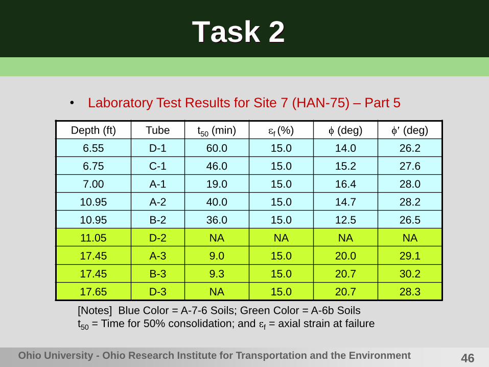
Task 2
• Laboratory Test Results for Site 7 (HAN-75) – Part 5
Depth (ft) Tube t50 (min) f (%) (deg) (deg)
6.55 D-1 60.0 15.0 14.0 26.2
6.75 C-1 46.0 15.0 15.2 27.6
7.00 A-1 19.0 15.0 16.4 28.0
10.95 A-2 40.0 15.0 14.7 28.2
10.95 B-2 36.0 15.0 12.5 26.5
11.05 D-2 NA NA NA NA
17.45 A-3 9.0 15.0 20.0 29.1
17.45 B-3 9.3 15.0 20.7 30.2
17.65 D-3 NA 15.0 20.7 28.3
[Notes] Blue Color = A-7-6 Soils; Green Color = A-6b Soils
t50 = Time for 50% consolidation; and f = axial strain at failure
47Ohio University - Ohio Research Institute for Transportation and the Environment
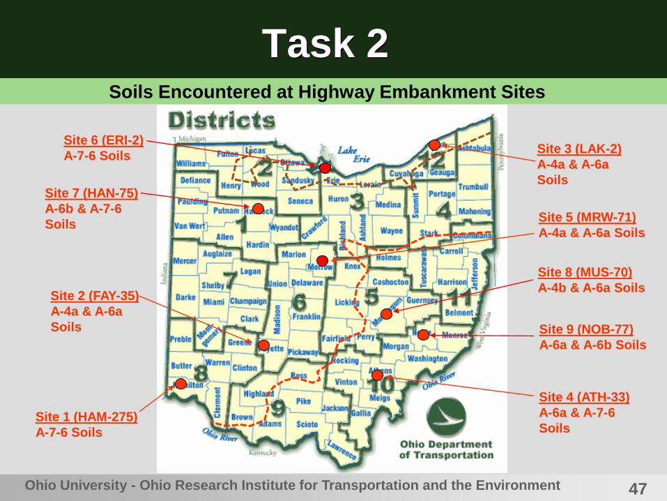
Task 2
Site 1 (HAM-275)
A-7-6 Soils
Site 2 (FAY-35)
A-4a & A-6a
Soils
Site 4 (ATH-33)
A-6a & A-7-6
Soils
Site 3 (LAK-2)
A-4a & A-6a
Soils
Site 5 (MRW-71)
A-4a & A-6a Soils
Site 6 (ERI-2)
A-7-6 Soils
Site 7 (HAN-75)
A-6b & A-7-6
Soils
Site 8 (MUS-70)
A-4b & A-6a Soils
Site 9 (NOB-77)
A-6a & A-6b Soils
Soils Encountered at Highway Embankment Sites

48Ohio University - Ohio Research Institute for Transportation and the Environment
Task 3
Empirical Correlations
• SPT-N Value vs. Unconfined Compression Strength qu
for Cohesive Soils – Terzaghi et al (1996)
SPT-(N60)1 Stiffness Unconfined Strength (psi)
< 2 very soft < 3.6
2-4 soft 3.6-7.3
4-8 medium stiff 7.3-14.5
8-15 stiff 14.5-29
15-30 very stiff 29-58
> 30 hard > 58

49Ohio University - Ohio Research Institute for Transportation and the Environment
Task 3
Empirical Correlations
• SPT-N Value vs. Unconfined Compression Strength qu
for Cohesive Soils – Terzaghi et al (1996)
SPT-(N60)1 Unconf. Strength (psi)
Terzaghi: A-4
Unconfined Strength (psi)
Measured: A-4
< 2 < 3.6 (No data)
2-4 3.6-7.3 (No data)
4-8 7.3-14.5 (No data)
8-15 14.5-29 45.1
15-30 29-58 19.1, 30.2, 30.3, 46.1, 48.9
> 30 > 58 20.8, 25.2, 41.0, 71.3, 79.0
[Note] Values in red are outside the Terzaghi range (45.5% outside).
50Ohio University - Ohio Research Institute for Transportation and the Environment
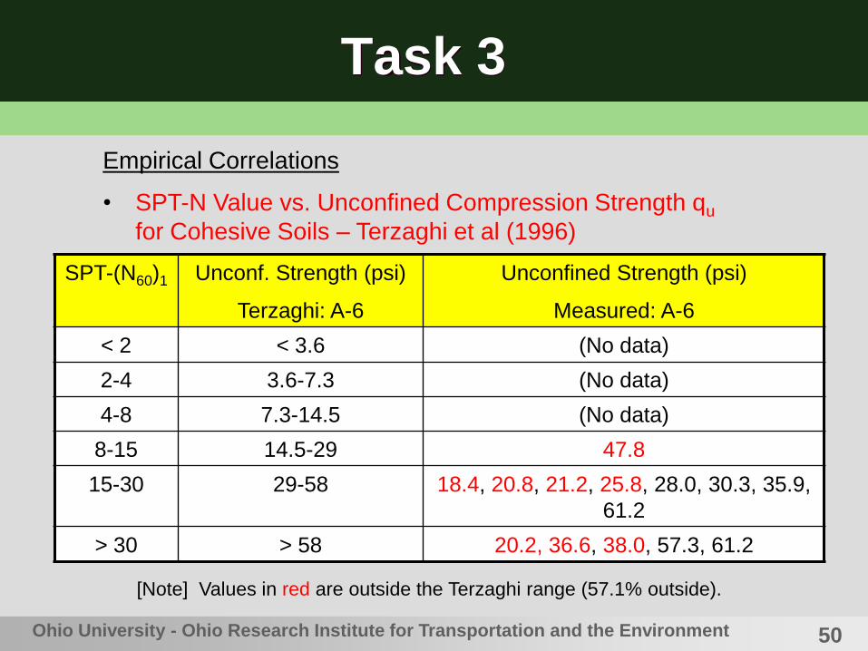
Task 3
Empirical Correlations
• SPT-N Value vs. Unconfined Compression Strength qu
for Cohesive Soils – Terzaghi et al (1996)
SPT-(N60)1 Unconf. Strength (psi)
Terzaghi: A-6
Unconfined Strength (psi)
Measured: A-6
< 2 < 3.6 (No data)
2-4 3.6-7.3 (No data)
4-8 7.3-14.5 (No data)
8-15 14.5-29 47.8
15-30 29-58 18.4, 20.8, 21.2, 25.8, 28.0, 30.3, 35.9,
61.2
> 30 > 58 20.2, 36.6, 38.0, 57.3, 61.2
[Note] Values in red are outside the Terzaghi range (57.1% outside).

51Ohio University - Ohio Research Institute for Transportation and the Environment
Task 3
Empirical Correlations
• SPT-N Value vs. Unconfined Compression Strength qu
for Cohesive Soils – Terzaghi et al (1996)
SPT-(N60)1 Unconf. Strength (psi)
Terzaghi: A-7-6
Unconfined Strength (psi)
Measured: A-7-6
< 2 < 3.6 (No data)
2-4 3.6-7.3 (No data)
4-8 7.3-14.5 (No data)
8-15 14.5-29 18.9, 21.3, 21.2, 24.3
15-30 29-58 16.9, 18.7, 24.8, 30.6, 39.4, 41.8
> 30 > 58 24.6, 39.4, 46.9
[Note] Values in red are outside the Terzaghi range (46.2% outside).

52Ohio University - Ohio Research Institute for Transportation and the Environment
Task 3
Empirical Correlations
• SPT-N Value vs. Unconfined Compression Strength qu –
Dept. of Navy (1982)
SPT-N60 qu of clays (low plasticity)
& clayey silts
qu of clays (med.
plasticity)
qu of clays (high
plasticity)
5 5.2 psi 10.4 psi 17.4 psi
10 10.4 psi 20.8 psi 34.7 psi
15 15.6 psi 31.3 psi 52.1 psi
20 20.8 psi 41.7 psi 69.4 psi
25 26.0 psi 52.1 psi 86.8 psi
30 31.2 psi 62.5 psi 104.1 psi
[Note] Low Plasticity (LL < 40); Med. Plasticity (LL 40 to 60); and
High Plasticity (LL > 60).

53
Task 3
Ohio University - Ohio Research Institute for Transportation and the Environment
SPT-N Value vs. Unconfined Compression Strength
qu – Dept. of Navy (1982)
Only half of the
data points fell
with the range
54Ohio University - Ohio Research Institute for Transportation and the Environment
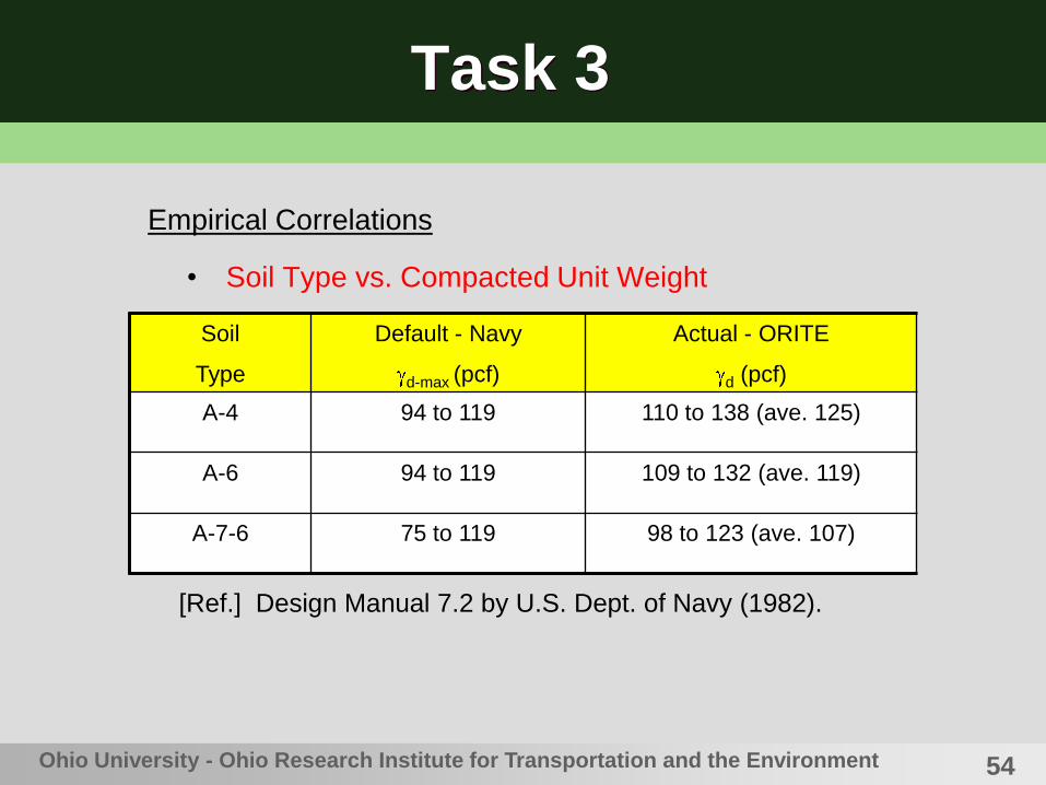
Task 3
• Soil Type vs. Compacted Unit Weight
Soil
Type
Default - Navy
d-max (pcf)
Actual - ORITE
d (pcf)
A-4 94 to 119 110 to 138 (ave. 125)
A-6 94 to 119 109 to 132 (ave. 119)
A-7-6 75 to 119 98 to 123 (ave. 107)
[Ref.] Design Manual 7.2 by U.S. Dept. of Navy (1982).
Empirical Correlations

55Ohio University - Ohio Research Institute for Transportation and the Environment
Task 3
Soil
Type
(deg.)
Dept. of Navy
Number of Data
Points - ORITE
(deg.)
Measured by ORITE
A-4 32 19 28.8 to 37.4 (Ave. 33.6)
A-6 28 31 28.3 to 37.8 (Ave. 32.7)
A-7-6 19-28 25 24.5 to 35.6 (Ave. 27.4)
[Ref.] Design Manual 7.2 by U.S. Dept. of Navy (1982).
• Soil Type vs. Effective Friction Angle
Empirical Correlations

56Ohio University - Ohio Research Institute for Transportation and the Environment
Task 3
Empirical Correlations
• Friction Angle vs. Plasticity Index PI – Terzaghi et al.
(1996)
PI (%) (deg) PI (%) (deg)
10 33.3 50 25.6
20 30.8 60 24.6
30 29.2 70 23.8
40 27.1 80 23.1
[Note] The actual value may be off by at least + 3 degrees.

57
Task 3
Ohio University - Ohio Research Institute for Transportation and the Environment
Friction Angle vs. Plasticity Index PI – Terzaghi et al. (1996)
Band width = average + 3°
58
Task 3
Ohio University - Ohio Research Institute for Transportation and the Environment
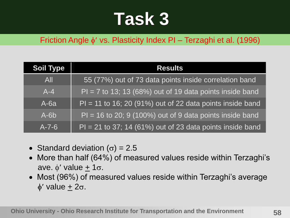
Friction Angle vs. Plasticity Index PI – Terzaghi et al. (1996)
Soil Type Results
All 55 (77%) out of 73 data points inside correlation band
A-4 PI = 7 to 13; 13 (68%) out of 19 data points inside band
A-6a PI = 11 to 16; 20 (91%) out of 22 data points inside band
A-6b PI = 16 to 20; 9 (100%) out of 9 data points inside band
A-7-6 PI = 21 to 37; 14 (61%) out of 23 data points inside band
Standard deviation ( ) = 2.5
More than half (64%) of measured values reside within Terzaghi’s
ave. value + 1 .
Most (96%) of measured values reside within Terzaghi’s average
value + 2 .
59Ohio University - Ohio Research Institute for Transportation and the Environment
Task 3
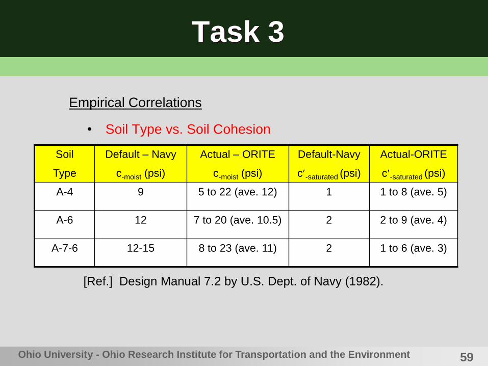
• Soil Type vs. Soil Cohesion
Soil
Type
Default – Navy
c-moist (psi)
Actual – ORITE
c-moist (psi)
Default-Navy
c -saturated (psi)
Actual-ORITE
c -saturated (psi)
A-4 9 5 to 22 (ave. 12) 1 1 to 8 (ave. 5)
A-6 12 7 to 20 (ave. 10.5) 2 2 to 9 (ave. 4)
A-7-6 12-15 8 to 23 (ave. 11) 2 1 to 6 (ave. 3)
[Ref.] Design Manual 7.2 by U.S. Dept. of Navy (1982).
Empirical Correlations

60Ohio University - Ohio Research Institute for Transportation and the Environment
Task 3
Corrected SPT-N
Values (Field)
Soil Index
Properties (Lab)
Unconfined Compr.
Strength (Lab)
C-U Triaxial Test
Results (Lab)
Diagram Showing Different Correlation Paths
Corr. 1
Corr. 2 Corr. 3
Corr. 4
Corr. 5
Corr
. 6
61Ohio University - Ohio Research Institute for Transportation and the Environment
Task 3
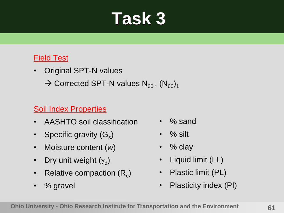
Field Test
• Original SPT-N values
Corrected SPT-N values N60 , (N60)1
Soil Index Properties
• AASHTO soil classification
• Specific gravity (Gs)
• Moisture content (w)
• Dry unit weight ( d)
• Relative compaction (Rc)
• % gravel
• % sand
• % silt
• % clay
• Liquid limit (LL)
• Plastic limit (PL)
• Plasticity index (PI)

62Ohio University - Ohio Research Institute for Transportation and the Environment
Task 3
Unconfined Compression Test
• Strength (qu)
• Undrained cohesion (cu)
• Moisture content
• Dry unit weight
• Relative compaction
C-U Triaxial Compression Test
• Dry unit weight
• Relative compaction
• Final moisture content
• Time for 50% consolidation
(t50)
• Angle of internal friction (
• Undrained cohesion (cu)
• Effective angle of internal
friction (
• Effective cohesion (c )
Y
Y
Y
Y
Y

63Ohio University - Ohio Research Institute for Transportation and the Environment
Task 3
• Higher Polynomial
• Logarithmic
• Exponential
• Power
• Hyperbolic
• Reciprocal
Y = a0 + a1X + a2X2 + …
Y = b + Ln(X)
Y = b emX
Y = b xm
Y = (b + mX)/X
Single-Variable Models for Statistical Analysis
Y = b + m(1/X)

64
Task 3• Single-Variable Regression Results for A-4a Soils
Independent Variable x Model Equation (coeff. of determination)
Time for 50% consolidation Hyperbolic = (24.19x – 0.556)/x (r2 = 0.923)
% clay Linear cu = -1.469x + 55.38 (r2 = 0.949)
% gravel Hyperbolic cu = (15.97x – 24.36)/x (r2 = 0.939)
% silt 2nd Polyn. cu = -0.256x2 + 22.05x – 454.72 (r2 = 0.900)
Time for 50% consolidation Hyperbolic = (28.95x + 15.10)/x (r2 = 0.988)
Plasticity index Hyperbolic = (35.13x – 15.82)/x (r2 = 0.923)
% clay 2nd Polyn. c = -0.1655x2 + 8.596x – 96.136 (r2 = 0.989)
Plasticity index 2nd Polyn. c = -0.641x2 + 13.28x – 60.08 (r2 = 0.955)
[Note 1] The above results are based on analysis of data from the all nine sites.
[Note 2] No single-variable regression analysis results are possible for A-4b soils due to a small
sample size.
[Note 3] Units are – & (degrees), cu & c (psi), t50 (minutes), and PI (%).

65
Task 3• Single-Variable Regression Results for A-6a Soils
Independent Variable x Model Equation (coeff. of determination)
Time of 50% consolidation Hyperbolic = (18.85x + 8.17)/x (r2 = 0.930)
Unconf. compr. strength (qu) Hyperbolic = (27.17x – 245.7)/x (r2 = 0.828)
Specific gravity 2nd Polyn. cu = -1,846x2 + 9975x – 13,459 (r2 = 0.823)
Time for 50% consolidation Hyperbolic = (30.37x + 19.34)/x (r2 = 0.992)
% gravel Hyperbolic = (31.86x + 10.93)/x (r2 = 0.979)
Liquid limit Hyperbolic = (32.21x + 31.35)/x (r2 = 0.945)
% sand Hyperbolic = (38.13x - 108.5)/x (r2 = 0.927)
Time for 50% consolidation 2nd Polyn. c = 0.165x2 – 2.701x + 12.15 (r2 = 0.979)
% clay 2nd Polyn. c = -0.936x2 + 57.40x – 873.1 (r2 = 0.977)
% gravel 2nd Polyn. c = -2.07x2 + 22.63x – 55.84 (r2 = 0.934)
% silt Linear c = 1.380x – 49.71 (r2 = 0.929)
[Note 1] The above results are based on analysis of data from all nine sites.
[Note 2] Units are – & (degrees), cu & c (psi), t50 (minutes), qu (psi), and LL (%).
66
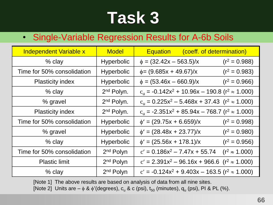
Task 3• Single-Variable Regression Results for A-6b Soils
Independent Variable x Model Equation (coeff. of determination)
% clay Hyperbolic = (32.42x – 563.5)/x (r2 = 0.988)
Time for 50% consolidation Hyperbolic = (9.685x + 49.67)/x (r2 = 0.983)
Plasticity index Hyperbolic = (53.46x – 660.9)/x (r2 = 0.966)
% clay 2nd Polyn. cu = -0.142x2 + 10.96x – 190.8 (r2 1.000)
% gravel 2nd Polyn. cu = 0.225x2 – 5.468x + 37.43 (r2 1.000)
Plasticity index 2nd Polyn. cu = -2.351x2 + 85.94x – 768.7 (r2 1.000)
Time for 50% consolidation Hyperbolic = (29.75x + 6.659)/x (r2 = 0.998)
% gravel Hyperbolic = (28.48x + 23.77)/x (r2 = 0.980)
% clay Hyperbolic = (25.56x + 178.1)/x (r2 = 0.956)
Time for 50% consolidation 2nd Polyn c = 0.186x2 – 7.47x + 55.74 (r2 1.000)
Plastic limit 2nd Polyn c = 2.391x2 – 96.16x + 966.6 (r2 1.000)
% clay 2nd Polyn c = -0.124x2 + 9.403x – 163.5 (r2 1.000)
[Note 1] The above results are based on analysis of data from all nine sites.
[Note 2] Units are – & (degrees), cu & c (psi), t50 (minutes), qu (psi), PI & PL (%).
67
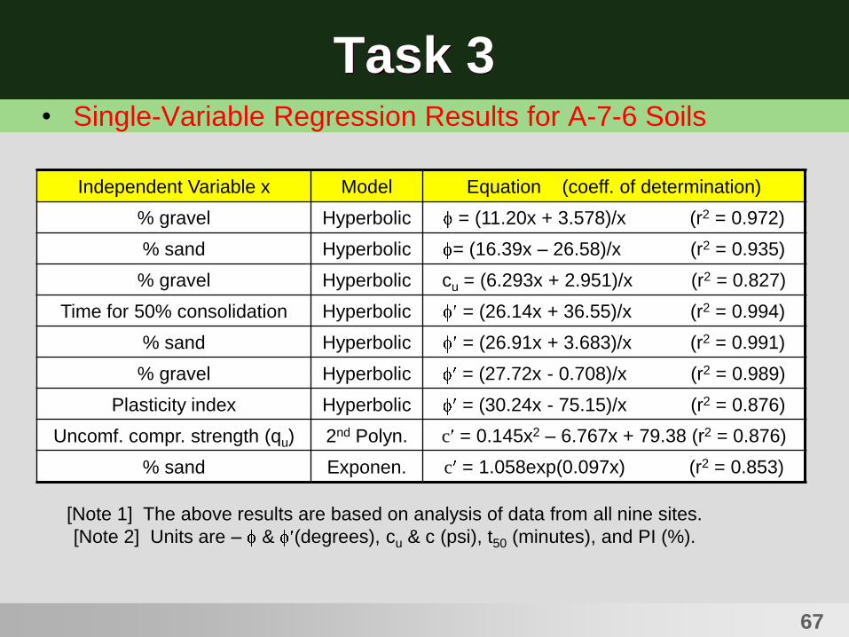
Task 3• Single-Variable Regression Results for A-7-6 Soils
Independent Variable x Model Equation (coeff. of determination)
% gravel Hyperbolic = (11.20x + 3.578)/x (r2 = 0.972)
% sand Hyperbolic = (16.39x – 26.58)/x (r2 = 0.935)
% gravel Hyperbolic cu = (6.293x + 2.951)/x (r2 = 0.827)
Time for 50% consolidation Hyperbolic = (26.14x + 36.55)/x (r2 = 0.994)
% sand Hyperbolic = (26.91x + 3.683)/x (r2 = 0.991)
% gravel Hyperbolic = (27.72x - 0.708)/x (r2 = 0.989)
Plasticity index Hyperbolic = (30.24x - 75.15)/x (r2 = 0.876)
Uncomf. compr. strength (qu) 2nd Polyn. c = 0.145x2 – 6.767x + 79.38 (r2 = 0.876)
% sand Exponen. c = 1.058exp(0.097x) (r2 = 0.853)
[Note 1] The above results are based on analysis of data from all nine sites.
[Note 2] Units are – & (degrees), cu & c (psi), t50 (minutes), and PI (%).

68Ohio University - Ohio Research Institute for Transportation and the Environment
Task 3
• Multi-Variable Linear Regression Model
Y = a0 + a1X1 + a2X2 + …+anXn
• Ranking of Correlations According to r2 values
• Backward Scheme or Forward Scheme
SPSS

69Ohio University - Ohio Research Institute for Transportation and the Environment
Task 3• Multi-Variable Linear Regression Analysis Results
Soil Type Independent Variables Equation (coeff. of determination)
A-4a % sand (x1), dry unit weight
(x2)
= 28.457 + 1.557x1 - 0.282x2 (r2 = 0.726)
A-6a % gravel (x1), moisture
content (x2)
c = 28.097 - 0.742x1 – 0.999x2 (r2 = 0.954)
[Note] The above results are based on analysis of data from the all nine sites.
Only two results shown above were reasonable. All the other
results were not meaningful due to multiple collinearity problems.
Multi-collinearity exists when there is a strong correlation between two or more
predictors (independent variables). If there is perfect collinearity between predictors, it
then becomes impossible to obtain unique estimates of the regression coefficients. There
are simply infinite number of combinations of coefficients that would work equally well.

70
Task 4
• Slope Stability Analysis
• Three Different Types
• Approximately Circular Shape
• Short-Term & Lon-Term Analyses
Ohio University - Ohio Research Institute for Transportation and the Environment
Shallow
Failure
Toe Circle Failure
(for > 53 )
Base Failure
71Ohio University - Ohio Research Institute for Transportation and the Environment
Task 4
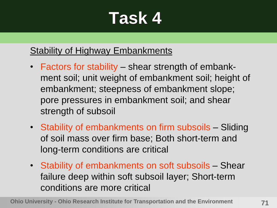
Stability of Highway Embankments
• Factors for stability – shear strength of embank-
ment soil; unit weight of embankment soil; height of
embankment; steepness of embankment slope;
pore pressures in embankment soil; and shear
strength of subsoil
• Stability of embankments on firm subsoils – Sliding
of soil mass over firm base; Both short-term and
long-term conditions are critical
• Stability of embankments on soft subsoils – Shear
failure deep within soft subsoil layer; Short-term
conditions are more critical

72Ohio University - Ohio Research Institute for Transportation and the Environment
Task 4
Stability of Highway Embankments
• Embankments constructed of a mixture of cohesive
soils and rock fragments – Long-term stability may
be a concern especially if the rock fragments were
derived from sedimentary rock (ex. shale).

73
Task 4
• Slope Stability Analysis by Method of Slices
Ohio University - Ohio Research Institute for Transportation and the Environment
FS = ----------(cLn + Wncos n)tan
(Wnsin n
Trial Failure Arc #1
Trial Failure Arc #2 n
Slice
n
Wn
Pn
Pn+1
Tn
Tn+1
Ln
Nn
n
L
ccc
c
c
Fs = factor of safety; c = cohesion; L = total length
of failure arc = R ; Wn = weight of slice n; = angle
of inclination for line connecting O and center of slice’s
bottom; = internal friction angle.
O
RR
O
In ordinary method,
Pn = Pn+1 and Tn = Tn+1

74
Task 4Slope Stability Analysis
• Computer Software GEOSLOPE
• Embankment Height -- 20, 30, and 40 ft
• Embankment Slope – 3H:1V ( = 18.4 ), 2.5H:1V
( = 21.8 ), and 2H:1V ( = 26.6 )
• Same fill material extended below the embankment
to form a foundation soil layer
• Short-Term ( = moist unit weight; cu; and = 0 )
• Long-Term ( = moist unit weight above water
table; sat = moist unit weight below water table; c ;
and )
Ohio University - Ohio Research Institute for Transportation and the Environment

75
Task 4
Ohio University - Ohio Research Institute for Transportation and the Environment
40-ft (12.2-m) High Embankment in A-7-6 Soil, Slope 2H:1V, Long-Term
SAMPLE
RESULT
76
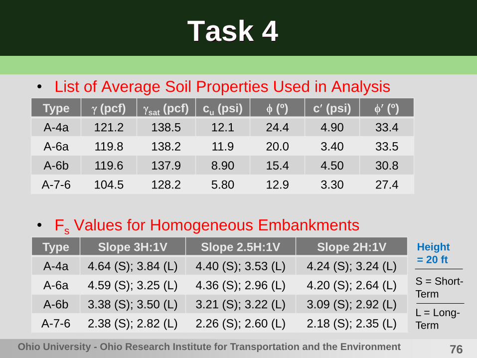
Task 4
• List of Average Soil Properties Used in Analysis
• Fs Values for Homogeneous Embankments
Ohio University - Ohio Research Institute for Transportation and the Environment
Type (pcf) sat (pcf) cu (psi) (º) c (psi) (º)
A-4a 121.2 138.5 12.1 24.4 4.90 33.4
A-6a 119.8 138.2 11.9 20.0 3.40 33.5
A-6b 119.6 137.9 8.90 15.4 4.50 30.8
A-7-6 104.5 128.2 5.80 12.9 3.30 27.4
Type Slope 3H:1V Slope 2.5H:1V Slope 2H:1V
A-4a 4.64 (S); 3.84 (L) 4.40 (S); 3.53 (L) 4.24 (S); 3.24 (L)
A-6a 4.59 (S); 3.25 (L) 4.36 (S); 2.96 (L) 4.20 (S); 2.64 (L)
A-6b 3.38 (S); 3.50 (L) 3.21 (S); 3.22 (L) 3.09 (S); 2.92 (L)
A-7-6 2.38 (S); 2.82 (L) 2.26 (S); 2.60 (L) 2.18 (S); 2.35 (L)
Height
= 20 ft
S = Short-
Term
L = Long-
Term

77
Task 4
• Fs Values for Homogeneous Embankments
• Fs Values for Homogeneous Embankments
Ohio University - Ohio Research Institute for Transportation and the Environment
Type Slope 3H:1V Slope 2.5H:1V Slope 2H:1V
A-4a 3.38 (S); 3.08 (L) 3.16 (S); 2.79 (L) 3.00 (S); 2.49 (L)
A-6a 3.35 (S); 2.66 (L) 3.12 (S); 2.38 (L) 2.96 (S); 2.09 (L)
A-6b 2.46 (S); 2.81 (L) 2.30 (S); 2.55 (L) 2.18 (S); 2.27 (L)
A-7-6 1.74 (S); 2.26 (L) 1.62 (S); 2.05 (L) 1.54 (S); 1.82 (L)
Type Slope 3H:1V Slope 2.5H:1V Slope 2H:1V
A-4a 2.73 (S); 2.74 (L) 2.52 (S); 2.47 (L) 2.34 (S); 2.18 (L)
A-6a 2.70 (S); 2.40 (L) 2.49 (S); 2.15 (L) 2.32 (S); 1.87 (L)
A-6b 1.99 (S); 2.50 (L) 1.83 (S); 2.25 (L) 1.71 (S); 1.99 (L)
A-7-6 1.40 (S); 2.02 (L) 1.29 (S); 1.82 (L) 1.20 (S); 1.60 (L)
Height
= 40 ft
S = Short-
Term
L = Long-
Term
Height
= 30 ft
S = Short-
Term
L = Long-
Term
78
Task 4
• The default soil property values available in the
literature do not represent the average properties
possessed by cohesive soil fills in Ohio very well.
• The empirical vs. PI correlation published by
Terzaghi et al. is applicable to A-4 and A-6 soils
found in Ohio.
• The empirical qu vs. (N60)1 correlation published by
the U.S. Dept. of Navy is not very reliable for
cohesive soils in Ohio.
Ohio University - Ohio Research Institute for Transportation and the Environment
Conclusions

79
Task 4
• Many statistically strong single-variable
correlations were identified for predicting shear
strength properties of highway embankment fill
soils.
• Very few linear multi-variable correlations surfaced
for shear strength properties of Ohio embankment
fill materials, due to multiple collinearity problems
existing among the data set.
Ohio University - Ohio Research Institute for Transportation and the Environment
Conclusions

80
Task 4
• Highway embankment slopes made from A-4a
soils exhibited the highest resistance against slope
failure. Highway embankment slopes made from
A-7-6 soils exhibited the lowest resistance against
slope failure.
Ohio University - Ohio Research Institute for Transportation and the Environment
Conclusions

81
Task 4
• Geotechnical Guidelines
• Level 1: Short-Term Analysis
• Set = 0 . Use the following default undrained
cohesion for each of the three major soil types found in
Ohio:
• A-4a & A-4b soils …………………… c = 9 to 12 psi
• A-6a & A-6b soils ………..….……… c = 8 to 11 psi
• A-7-6 soils ……………..………….… c = 6 to 11 psi
82
Task 4
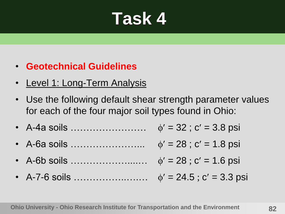
• Geotechnical Guidelines
• Level 1: Long-Term Analysis
• Use the following default shear strength parameter values
for each of the four major soil types found in Ohio:
• A-4a soils …………………… = 32 ; c = 3.8 psi
• A-6a soils …………………... = 28 ; c = 1.8 psi
• A-6b soils ………………....… = 28 ; c = 1.6 psi
• A-7-6 soils ……………..….… = 24.5 ; c = 3.3 psi
Ohio University - Ohio Research Institute for Transportation and the Environment

83
Task 4
• Geotechnical Guidelines
• Level 1: Long-Term Analysis (alternative)
• Determine liquid and plastic limits of the soil.
Compute plasticity index (PI). Estimate the
effective friction angle using the Terzaghi’s
empirical vs. PI correlation chart. For A-4 and A-
6 soils, use the average value resulting from the
chart. For A-7-6 soils, the lower the average
value shown in the chart by 2.5 (one standard
deviation).

84
Task 4
• Geotechnical Guidelines
• Level 2: Short-Term & Long-Term Analyses
• Take advantage of some index property data
available from laboratory tests. Use any of the
correlation equations (w/ r2 values > 0.8) previously
shown for effective friction angle in:
• Slide #64 ………………… A-4a soils
• Slide #65 ………………… A-6a soils
• Slide #66 ………………… A-6b soils
• Slide #67 ………………… A-7-6 soils

85
Task 4
• Geotechnical Guidelines
• Embankment slopes built with A-6b soils should
not be taller than 30 ft (9.1 m). Steepest slope shall
be 2H:1V.
• Embankment slopes built with A-7-6 soils should
not be taller than 20 ft (6.1 m). Steepest slope shall
be 2H:1V.
Ohio University - Ohio Research Institute for Transportation and the Environment
86Ohio University - Ohio Research Institute for Transportation and the Environment
References
• ASTM (2004). “Standard Test Method for Consolidated Undrained Triaxial Compression Test for Cohesive Soils.” Designation D 4767-04, West Conshohocken, PA, pp. 887-899.
• Clough, R. W., and Woodward, R. J. (1967). “Analysis of Embankment Stresses and Deformations.” Journal of Soil Mechanics & Foundations Division, ASCE, Vol. 93, No. SM 4, pp. 529-549.
• Dept. of Navy (1982). Soil Mechanics Design Manual, NAVFACDM-7.1, Alexandria, VA.
• Field, A. (2005). Discovering Statistics Using SPSS, 2nd
Edition, SAGE Publications, London, 779 pp.
• Han, X. (2010). “Shear Strength and Stability of Highway Embankments in Ohio.” MS Thesis, Civil Engineering Dept., Ohio University, Athens, OH, 153 pp.

87Ohio University - Ohio Research Institute for Transportation and the Environment
References
• Holko, J. (2008). “Shear Strength Correlations for Ohio Highway Embankment Soils.” MS Thesis, Civil Engineering Dept., Ohio University, Athens, OH, 209 pp.
• Johnson, G. O. (1975). “Engineering Characteristics of Ohio Soil Series.” Report No. OHIO-DOT-75, 3 Volumes, Columbus, OH.
• Masada, T. (2009). Final Project Report Titled “Shear Strength of Clay and Silt Embankments.” FHWA/OH-2009/7, Submitted to Ohio DOT, Civil Engineering Dept., Ohio University, Athens, OH, 300+ pp.
• Ohio Department of Transportation (ODOT). (2006). Construction Inspection Manual of Procedure, Columbus, OH, pp. 962-963.
• Terzaghi, K, Peck, R. B., and Mesri, G. (1996). Soil Mechanics in Engineering Practice, 2nd Edition, Wiley & Sons, Inc. New York, NY, 549 pp.
88
References
• Walpole, R. E., and Myers, R. H. (1989). Probability and
Statistics for Engineers and Scientists, 4th Edition, Macmillan
Publishing Co., New York, NY, 765 pp.
• Wu, T. H. (1958). “Geotechnical Properties of Glacial Lake
Clays.” Journal of Soil Mechanics and Foundations Division,
ASCE, Vol. 84, No. SM 3, pp. 1–36.
Ohio University - Ohio Research Institute for Transportation and the Environment

http://webce.ent.ohiou.edu/orite/
www.ohio.edu/engineering
Thank you for listening to my
presentation!
Dr. Terry Masada
Professor, Assistant Chair
Civil Engineering Dept.
149 Stocker Center
Ohio University, Athens, OH
Tel: (740) 593-2474
Fax: (740) 593-0625
E-Mail: [email protected]