HIGHWAY 63:11 PINCH POINT EAST WALL NORTH OF … · Highway 63:11 to the north of the Athabasca...
8
HIGHWAY 63:11 PINCH POINT EAST WALL NORTH OF ATHABASCA RIVER BRIDGE IN FORT MCMURRAY, ALBERTA Tarek Abdelaziz, Donald Proudfoot Thurber Engineering Ltd., Edmonton, Alberta, Canada Roger Skirrow Alberta Transportation– Geotechnical and Materials Section, Edmonton, Alberta, Canada Dan Morin AECOM– Bridge Group, Edmonton, Alberta, Canada ABSTRACT Highway 63:11 to the north of the Athabasca River Bridge in the urban service area of Fort McMurray, Alberta is situated on a narrow river terrace bench that represents a “Pinch Point” for transportation and utility corridors. The highway at this location is constrained between a meta-stable colluvial valley slope to the west and a steep eroded bank of the Athabasca River to the east. The highway expansion project at this location from 4 to 8 lanes created geometric constraints that required the construction of two parallel pile walls to confine the road cross section. The east side wall which is the subject of this paper is 320 m long and consists of up to 6 m high above-ground cast-in-place concrete wall supported on a below grade pile wall. The pile wall consists of 134 rock socketed piles and 113 high capacity grouted multi-strand tendons bonded into a limestone formation. The eroded slope above the river bank was protected using a high performance turf reinforcement mat to reduce the lateral movement of the wall. The paper provides a brief summary of the design and construction aspects of the east wall and includes a discussion about the instrumentation monitoring results. RÉSUMÉ À Fort McMurray en Alberta, l’autoroute 63:11 longeant la rive nord du fleuve Athabasca se situe sur une terrace étroite donnant un rétrécissement local à l’espace allouée à la voie navigable ainsi qu’au corridor de services adj acent. L’autoroute est cintrée par un talus métastable de sols colluviaux à l’ouest et par l’abrupte berge érodée du fleuve à l’est. Un projet d’augmentation du nombre de voies à cet endroit de 4 à 8 à requiert deux murets de soutènement construits parallèle à la chaussée. Le muret Est, le sujet de cet article, à une longueur de 320 m et est composé de pieux en béton coulés en place, avec une hauteur allant jusqu’à 6 m au-dessus du niveau du sol et appuyé sur un muret enfouis. Le muret est composé de 134 pieux emboités dans un socle calcaireux et de 113 ancrages composés de tirants à câbles à haute capacité ancrés dans le roc. Afin d’atténuer le mouvement latéral du muret, le talus érodé en amont de la chaussé fut recouvert d’un tapis de renforcement de gazon. Cet article résume de la conception et de la construction du muret Est ainsi qu’une discussion sur les données recueillies par les instruments. 1 INTRODUCTION Highway 63 is a 443 kilometre long provincial highway with an average annual daily traffic of more than 30,000 vehicles. The highway is the primary corridor to the oil sand developments in and around the Urban Service Area of Fort McMurray in northern Alberta. In order to accommodate the rapid population growth in Fort McMurray, Alberta Transportation (AT) made a commitment to upgrade the corridor to improve traffic safety, reduce congestion, and accommodate over- dimensioned loads. To the north of the Athabasca River Bridge within Fort McMurray, the highway was to be upgraded from 4 to 6 mainline lanes along with 2 adjacent collector-distributor lanes. The highway at this location was constructed on a narrow river terrace situated between the toe of a meta- stable colluvial valley slope to the west and a steep eroded bank of the Athabasca River to the east. This existing geographic constraint created a physical “Pinch Point” that governed the highway upgrading design. Figure 1 presents a satellite image of the project site. Figure 1. Satellite image showing site location Pinch Point Athabasca River Bridge
Transcript of HIGHWAY 63:11 PINCH POINT EAST WALL NORTH OF … · Highway 63:11 to the north of the Athabasca...

HIGHWAY 63:11 PINCH POINT EAST WALL NORTH OF ATHABASCA RIVER BRIDGE IN FORT MCMURRAY, ALBERTA Tarek Abdelaziz, Donald Proudfoot Thurber Engineering Ltd., Edmonton, Alberta, Canada Roger Skirrow Alberta Transportation– Geotechnical and Materials Section, Edmonton, Alberta, Canada Dan Morin AECOM– Bridge Group, Edmonton, Alberta, Canada ABSTRACT Highway 63:11 to the north of the Athabasca River Bridge in the urban service area of Fort McMurray, Alberta is situated on a narrow river terrace bench that represents a “Pinch Point” for transportation and utility corridors. The highway at this location is constrained between a meta-stable colluvial valley slope to the west and a steep eroded bank of the Athabasca River to the east. The highway expansion project at this location from 4 to 8 lanes created geometric constraints that required the construction of two parallel pile walls to confine the road cross section. The east side wall which is the subject of this paper is 320 m long and consists of up to 6 m high above-ground cast-in-place concrete wall supported on a below grade pile wall. The pile wall consists of 134 rock socketed piles and 113 high capacity grouted multi-strand tendons bonded into a limestone formation. The eroded slope above the river bank was protected using a high performance turf reinforcement mat to reduce the lateral movement of the wall. The paper provides a brief summary of the design and construction aspects of the east wall and includes a discussion about the instrumentation monitoring results. RÉSUMÉ À Fort McMurray en Alberta, l’autoroute 63:11 longeant la rive nord du fleuve Athabasca se situe sur une terrace étroite donnant un rétrécissement local à l’espace allouée à la voie navigable ainsi qu’au corridor de services adjacent. L’autoroute est cintrée par un talus métastable de sols colluviaux à l’ouest et par l’abrupte berge érodée du fleuve à l’est. Un projet d’augmentation du nombre de voies à cet endroit de 4 à 8 à requiert deux murets de soutènement construits parallèle à la chaussée. Le muret Est, le sujet de cet article, à une longueur de 320 m et est composé de pieux en béton coulés en place, avec une hauteur allant jusqu’à 6 m au-dessus du niveau du sol et appuyé sur un muret enfouis. Le muret est composé de 134 pieux emboités dans un socle calcaireux et de 113 ancrages composés de tirants à câbles à haute capacité ancrés dans le roc. Afin d’atténuer le mouvement latéral du muret, le talus érodé en amont de la chaussé fut recouvert d’un tapis de renforcement de gazon. Cet article résume de la conception et de la construction du muret Est ainsi qu’une discussion sur les données recueillies par les instruments. 1 INTRODUCTION Highway 63 is a 443 kilometre long provincial highway with an average annual daily traffic of more than 30,000 vehicles. The highway is the primary corridor to the oil sand developments in and around the Urban Service Area of Fort McMurray in northern Alberta. In order to accommodate the rapid population growth in Fort McMurray, Alberta Transportation (AT) made a commitment to upgrade the corridor to improve traffic safety, reduce congestion, and accommodate over-dimensioned loads. To the north of the Athabasca River Bridge within Fort McMurray, the highway was to be upgraded from 4 to 6 mainline lanes along with 2 adjacent collector-distributor lanes. The highway at this location was constructed on a narrow river terrace situated between the toe of a meta-stable colluvial valley slope to the west and a steep eroded bank of the Athabasca River to the east. This existing geographic constraint created a physical “Pinch
Point” that governed the highway upgrading design. Figure 1 presents a satellite image of the project site.
Figure 1. Satellite image showing site location
Pinch Point
Athabasca River Bridge

Figure 2. Artistic depiction of upgraded Hwy 63 and East and West Retaining Walls, looking north In order to accommodate the substantial increase in the out-to-out width of the roadway corridor from 33 m to 68 m a 420 m long secant pile wall, known as the West or Hillside Pile Wall (WPW), was constructed on the west side of the highway, and a 320 m wall, known as the Riverside or East Pile Wall (EPW) was constructed on the east side of the highway. An artistic depiction of the east and west walls is shown on Figure 2. The construction of both walls was completed between June 2010 and July 2012 and the construction cost was in the range of 21 Million Dollars. Although both walls are equally important to the success of the overall widening scheme, the EPW is the focus of this paper. Provided herein is a summary of the design and construction aspects of the wall, including a brief discussion of the instrumentation monitoring results. 2 SITE DESCRIPTION 2.1 General A geotechnical investigation, consisting of auger and core holes and installation of slope inclinometers and piezometers, was carried out by Thurber Engineering Ltd. between 2006 and 2008. The study characterized the sub-surface conditions and provided design recommendations for the walls. A shaded relief plan showing the old and upgraded highway alignments, and the wall locations is presented in Figure 3. A simplified stratigraphic cross section of the highway at the pinch point location is also presented in Figure 4. 2.2 Geomorphological History
The broad basin north of Fort McMurray existed before the advance of the continental glacier. It was drained, probably to the north, by small streams. An unknown amount of material has been removed by glacial scour. Regional recession of the continental glacier in a general north eastward direction occurred approximately 9000 years ago. Drainage channels in the direction of regional
topographical dip (to the northwest) were blocked by ice, and vast pre-glacial lakes ponded against the glacier front. The Clearwater River valley and much of the present course of the Athabasca River north of Fort McMurray once served as the channel for south eastward glacial meltwater and pre-glacial lake drainage. After breaching of ice barriers and further glacial recession, a new regional drainage system was imposed upon the area. The Athabasca River displaced northward by disruption of drainage, occupied its present-day position and rapidly excavated its steep, deep valley west of Fort McMurray. The progressive down-cutting action by the river resulted in the development of landslides in the present valley slopes and the formation of the narrow river terrace and the eroded bank to the east of Highway 63 at the study area location. Although the valley slopes are currently moving at a very slow rate (i.e. creeping), accelerated movements have occurred due to disturbance of these sensitive valley slopes, most notably in response to previous highway twinning projects and urban developments.
2.3 Surficial and Bedrock Units Three major surficial geology units are present within and in the general vicinity of the study area. These units include alluvial, colluvial, and glacial Deposits (Fenton et al. 2013). The alluvial deposits from the river terrace are located below the highway and consists of sand, gravel and silt layers. Colluvial deposits are located on the valley slopes of the Athabasca River and originates from erosion and landslide events through surficial deposits and bedrock formations in valley settings. Most of the colluvium displays slow creep movement towards the base of the valleys. The glacial deposits consist of a mixture of clay, silt and sand, as well as minor pebbles, cobbles and boulders, and are generally present in the uplands plateau area. Three major bedrock units are present within the study area (Prior et al. 2013). These units include the Clearwater, McMurray, and Devonian Formations. The Clearwater Formation underlies the plateau and the colluvial deposits in the upper portions of the valley slopes. It consists mainly of extremely weak to weak high plastic clay shale with occasional interbeds of weak to strong siltstone and sandstone. The stress relief due to the down-cutting of the river has weakened the Clearwater clay shale and made it highly susceptible to slumping and gullying. It is therefore considered to be the main source of the colluvium deposits and the landslides along Highway 63 valley slopes. The colluvial deposits drape over the valley slopes and accumulate at the base of the valley. The Clearwater Formation is underlain by the McMurray Formation. This formation outcrops extensively along the valley slopes. It typically consists of interbedded oil impregnated sand, siltstone and clay shale. The McMurray Formation contains three members: The upper McMurray - fine grained quartz sands, oil cemented; the Middle McMurray - medium grained quartz sand, oil cemented, lenses of siltstone, shale and coal, and; the Lower McMurray - conglomerate, detrital clays and shales, siltstone and coarse grained sands. The
East Pile Wall
West Pile Wall

Figure 3. Shaded relief plan showing pile walls at the Pinch Point location
Figure 4. Simplified stratigraphic cross section at the Pinch Point location
Figure 5. Design profile along the EPW alignment

Clearwater and McMurray Formations are of the Cretaceous Period, 70 to 130 million years old. Underlying these formations is limestone bedrock of the Devonian Period ,350 to 400 million years old. The Devonian bedrock consists primarily of limestone of the Waterways Formation. The limestone outcrops for several kilometers along the Athabasca River banks and is known to contain sporadic solution cavities and karst. The limestone ranges from weak clayey "argillaceous" limestone to moderately strong to very strong biomicritic and nodular limestone. Very weak, high plastic calcareous shale layers, are frequently present interbedded within the limestone. The upper surface of the Devonian Formation limestone is an erosional unconformity upon which the oilsand and the Clearwater shale were deposited. At depth the Devonian bedrock is comprised of a succession of carbonate rocks and evaporates which has been reported to be Precambrian granite of at least 600 million years old. The granite is found some 240 m below the present upland surface (Carrigy, 1959). 2.4 Surface and Sub-surface Conditions The highway at the study area was a four-lane divided roadway that was originally constructed on a 33 m wide terrace of the Athabasca River valley. The highway grade is located about 20 m above the river level and the river bank slopes to the east of the highway are steeply inclined at 45 to 60 degrees to horizontal. The limestone bedrock is typically visible along the steep river banks. The river bank slopes to the east of the highway have sparse vegetation cover and are partially under-scoured hanging trees. An existing pipeline is present near the top of bank to the east of the highway location. The highway alignment is bounded on the west by meta-stable valley slopes. The valley slopes are about 55 m high and inclined at 15 to 26 degrees to horizontal. Oil sand is visible on the steeply inclined valley slopes. The valley slopes are typically covered with mature tilting trees and deadfall. An ancient landslide block is visible in the valley slopes within the study area, as shown in Figure 3. The subsurface conditions at the highway generally consist of clay fill underlain by about 2 to 10 m of interbedded loose sand and firm clay (alluvial deposits) over 1 to 2 m of dense to very dense oil sand with clay shale interbeds overlying interbedded weak to extremely argillaceous limestone and strong to medium strong nodular and biomicritic limestone bedrock. The oil sand thickness appears to thin out near the banks of the river and the limestone surface elevation varies by about 3 to 4 m along the highway alignment. The upper 1 m of the limestone bedrock is closely jointed and weathered. The uniaxial compression strength of the McMurray formation typically ranges from less than 1 to 3 MPa (i.e. weak to extremely weak bedrock). For the Devonian Formation, the uniaxial compression strength typically ranges from less than 1 MPa (i.e. extremely weak argillaceous limestone bedrock) to more than 50 MPa (i.e. strong nodular and biomicritic limestone). Groundwater table is about 5 to 13 m below ground surface.
3 EAST PILE WALL (EPW) 3.1 Pile Wall Design Details The highway is bounded on the east side by an existing buried pipeline and the eroded Athabasca River steep banks. In order to accommodate the additional lanes within the pinch point footprint, a retaining wall was constructed along the east side of highway to retain the highway widening fill and avoid the encroachment of the fill into the pipeline ROW and the river bank. A design profile along the East Pile Wall (EPW) alignment is presented in Figure 5. As Figure 5 shows, the original alignment was altered by either lowering or raising existing grades to establish the new roadway. To facilitate optimization of the design, the wall was divided into four design sections, Segments A to D. The differentiation between the design segments was based on the loading condition and available passive resistance on the downslope side of the wall location. At some locations, where the piles were installed very close to the crest of the steeply inclined eroded bank slopes, the passive resistance from the alluvial deposits was reduced or discounted in the design to account for potential future erosion, most notably in areas with bare to sparse vegetation cover. The EPW consists of an above-ground cast-in-place concrete wall, structurally tied to and supported on an underground tangent pile wall. A typical cross section of the wall is presented in Figure 6. The above-ground supports up to 6 m of the new highway fill. The underground wall consists of 134 cast-in-place concrete structural piles socketed at least 7 m into the strong limestone. The piles are 1.2 m diameter and 11 to 18 m long. To limit the wall deflection in Segments B to D, the original design included one row of 36 to 46 mm diameter high capacity Double Corrosion Protection (DCP) permanent grouted anchors. The anchors were to be inclined at 30o and had 6 to 10 m bond zone into the strong limestone. The pile cap was provided with 225 mm diameter PVC ducts and recesses to accommodate the ground anchors and anchorage system. A few of the vertical bars of the pile reinforcement cage were bundled to provide constructability tolerances and to avoid damaging the vertical rebar projection into the pile cap during anchor drilling. 3.2 Construction The construction of the wall was completed between June 2010 and October 2011 with a total construction cost of about $7 Million. The construction involved the following activities in sequence: installation of piles; pile cap construction; installation and stressing of anchors; construction of above-ground wall; backfilling behind the wall and surfacing new highway. An access bench was constructed on the east side of the highway to establish a working platform for construction activities. The piles were installed using a SoilMec R-625 hydraulic rotary rig. Rock augers and core barrels were used to advance the pile holes into the limestone and the rock sockets were
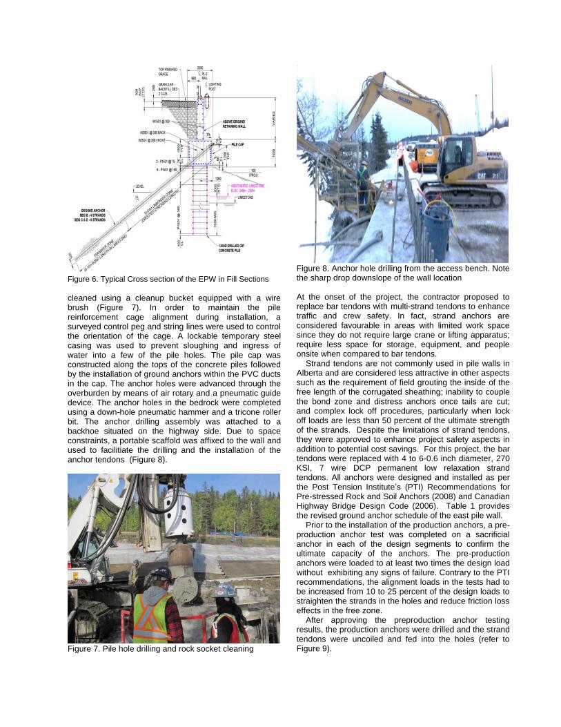
Figure 6. Typical Cross section of the EPW in Fill Sections
cleaned using a cleanup bucket equipped with a wire brush (Figure 7). In order to maintain the pile reinforcement cage alignment during installation, a surveyed control peg and string lines were used to control the orientation of the cage. A lockable temporary steel casing was used to prevent sloughing and ingress of water into a few of the pile holes. The pile cap was constructed along the tops of the concrete piles followed by the installation of ground anchors within the PVC ducts in the cap. The anchor holes were advanced through the overburden by means of air rotary and a pneumatic guide device. The anchor holes in the bedrock were completed using a down-hole pneumatic hammer and a tricone roller bit. The anchor drilling assembly was attached to a backhoe situated on the highway side. Due to space constraints, a portable scaffold was affixed to the wall and used to facilitiate the drilling and the installation of the anchor tendons (Figure 8).
Figure 7. Pile hole drilling and rock socket cleaning
Figure 8. Anchor hole drilling from the access bench. Note the sharp drop downslope of the wall location At the onset of the project, the contractor proposed to replace bar tendons with multi-strand tendons to enhance traffic and crew safety. In fact, strand anchors are considered favourable in areas with limited work space since they do not require large crane or lifting apparatus; require less space for storage, equipment, and people onsite when compared to bar tendons. Strand tendons are not commonly used in pile walls in Alberta and are considered less attractive in other aspects such as the requirement of field grouting the inside of the free length of the corrugated sheathing; inability to couple the bond zone and distress anchors once tails are cut; and complex lock off procedures, particularly when lock off loads are less than 50 percent of the ultimate strength of the strands. Despite the limitations of strand tendons, they were approved to enhance project safety aspects in addition to potential cost savings. For this project, the bar tendons were replaced with 4 to 6-0.6 inch diameter, 270 KSI, 7 wire DCP permanent low relaxation strand tendons. All anchors were designed and installed as per the Post Tension Institute’s (PTI) Recommendations for Pre-stressed Rock and Soil Anchors (2008) and Canadian Highway Bridge Design Code (2006). Table 1 provides the revised ground anchor schedule of the east pile wall. Prior to the installation of the production anchors, a pre-production anchor test was completed on a sacrificial anchor in each of the design segments to confirm the ultimate capacity of the anchors. The pre-production anchors were loaded to at least two times the design load without exhibiting any signs of failure. Contrary to the PTI recommendations, the alignment loads in the tests had to be increased from 10 to 25 percent of the design loads to straighten the strands in the holes and reduce friction loss effects in the free zone. After approving the preproduction anchor testing results, the production anchors were drilled and the strand tendons were uncoiled and fed into the holes (refer to Figure 9).
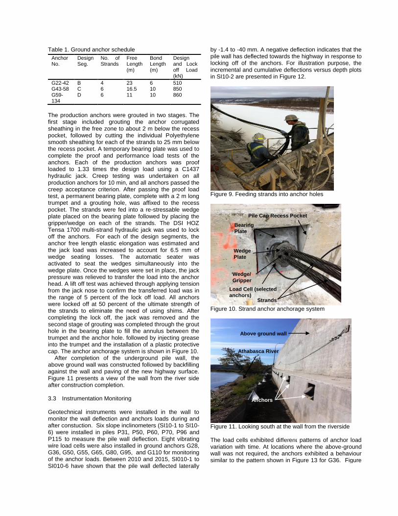
Table 1. Ground anchor schedule
Anchor No.
Design Seg.
No. of Strands
Free Length (m)
Bond Length (m)
Design and Lock off Load (kN)
G22-42 B 4 23 6 510 G43-58 C 6 16.5 10 850 G59-134
D 6 11 10 860
The production anchors were grouted in two stages. The first stage included grouting the anchor corrugated sheathing in the free zone to about 2 m below the recess pocket, followed by cutting the individual Polyethylene smooth sheathing for each of the strands to 25 mm below the recess pocket. A temporary bearing plate was used to complete the proof and performance load tests of the anchors. Each of the production anchors was proof loaded to 1.33 times the design load using a C1437 hydraulic jack. Creep testing was undertaken on all production anchors for 10 min, and all anchors passed the creep acceptance criterion. After passing the proof load test, a permanent bearing plate, complete with a 2 m long trumpet and a grouting hole, was affixed to the recess pocket. The strands were fed into a re-stressable wedge plate placed on the bearing plate followed by placing the gripper/wedge on each of the strands. The DSI HOZ Tensa 1700 multi-strand hydraulic jack was used to lock off the anchors. For each of the design segments, the anchor free length elastic elongation was estimated and the jack load was increased to account for 6.5 mm of wedge seating losses. The automatic seater was activated to seat the wedges simultaneously into the wedge plate. Once the wedges were set in place, the jack pressure was relieved to transfer the load into the anchor head. A lift off test was achieved through applying tension from the jack nose to confirm the transferred load was in the range of 5 percent of the lock off load. All anchors were locked off at 50 percent of the ultimate strength of the strands to eliminate the need of using shims. After completing the lock off, the jack was removed and the second stage of grouting was completed through the grout hole in the bearing plate to fill the annulus between the trumpet and the anchor hole. followed by injecting grease into the trumpet and the installation of a plastic protective cap. The anchor anchorage system is shown in Figure 10. After completion of the underground pile wall, the above ground wall was constructed followed by backfilling against the wall and paving of the new highway surface. Figure 11 presents a view of the wall from the river side after construction completion. 3.3 Instrumentation Monitoring Geotechnical instruments were installed in the wall to monitor the wall deflection and anchors loads during and after constuction. Six slope inclinometers (SI10-1 to SI10-6) were installed in piles P31, P50, P60, P70, P96 and P115 to measure the pile wall deflection. Eight vibrating wire load cells were also installed in ground anchors G28, G36, G50, G55, G65, G80, G95, and G110 for monitoring of the anchor loads. Between 2010 and 2015, SI010-1 to SI010-6 have shown that the pile wall deflected laterally
by -1.4 to -40 mm. A negative deflection indicates that the pile wall has deflected towards the highway in response to locking off of the anchors. For illustration purpose, the incremental and cumulative deflections versus depth plots in SI10-2 are presented in Figure 12.
Figure 9. Feeding strands into anchor holes
Figure 10. Strand anchor anchorage system
Figure 11. Looking south at the wall from the riverside The load cells exhibited different patterns of anchor load variation with time. At locations where the above-ground wall was not required, the anchors exhibited a behaviour similar to the pattern shown in Figure 13 for G36. Figure
Above ground wall
Athabasca River
Pile Cap
Anchors
Pile Cap Recess Pocket
Bearing
Plate
Wedge
Plate
Wedge/
Gripper
Strands
Load Cell (selected
anchors)

13 shows an instantaneous loss of a portion of the anchor load, followed by a slower gradual loss until the load exhibited minor fluctuation with time. A similar behaviour of load loss in anchors has been reported by Benmokrane et al. (1991). In general, the load loss in the anchors occurred within 60 days (Segment B) to 120 days (Segments C and D) after the installation date. The transition between the instantaneous and gradual drop of the load occurred within 45 days of locking off the anchors. The loss of anchor loads generally ranged from less than 10 percent (Segment B) to up 15 percent (Segments C and D). Since the anchors were locked off at 50 percent of the elastic yield stress of the steel, it was not possible to attribute the load reduction to stress relaxation. For the monitored anchors, it appears that the load loss tends to increase as the free length increases and the number of strands increases. It is speculated that the initial sharp reduction in anchor loads may have occurred due to seating losses and friction losses in response to the “wobble” effect. The gradual loss may be attributed to the non-simultaneous locking of anchors and re-distribution of loads along the wall with time. Relatively similar reductions in anchor loads have been observed in other pile wall projects and this phenomenon is not deemed a concern as long as it is not accompanied by unacceptable wall deflection and was serviceability issues.
Figure12. SI10-2: Incremental and cumulative deflections versus depth plots for Pile
Figure 14 illustrates a different pattern of behavior for anchors installed within the above-ground wall sections. Initially, the anchor showed a reduction in the load (similar to the pattern presented in Figure 13) followed by a gradual increase in the load before stabilizing with time. The increase in the anchor load corresponded to the placement and compaction of gravel backfill behind the wall. The increase in anchor loads ranged from 20 kPa
for 2 m high wall sections to up to 68 kPa for 6 m high wall sections.
Figure13. Variation in G36 load versus time
Figure14. Variation in G95 load versus time
4 RIVER BANK EROSION PROTECTION During and after construction, erosion and slumping occurred at a few locations in the steeply inclined alluviual river bank slopes, located immediately downslope of the wall. Due to environmental, aesthetic, and design concerns, erosion protection was provided downslope of the wall location. The design concern was related to the retrogression of the slump into the wall location and potential complete loss of passive resistance downslope of the wall location. The slope protection included hydro-seeding and placement of a High Performance Turf Reinforcement Mat, MacMat R, installed along the eroded face of the alluviual deposit. This product is a three dimensional geo-composite consisting of a twisted steel wire mesh filled with a spun finer mesh of polypropylene yarn. The mat was anchored to the prepared slope surface using U shaped pins, and 1x1 m2 grid of 1.5 m deep Manta Ray anchors and galvanized steel plates. The mat was also anchored to the limestone below the eroded surface and to the sides of the pile cap at the top of the slope. Due to the steepness of the slope, mountain climbers with safety

harness and cables anchored to the top of the wall were retained by the contractor to complete the installation (refer to Figures 15 a through b).
(a)
(b) Figure15. River bank erosion protection; (a) Mountain climbers installing MacMat R and (b) Hydro-seeded mat and final product
5 FUTURE WORK The acceptance “criterion” of the performance testing of anchors requires that the anchor measured elastic elongation should be greater than the minimum apparent length Threshold. This is to ensure that at least 80 percent of the load is transferred into the bond zone. However, this “criterion” is arbitrary and should only be considered as a guideline along with engineering judgement. In addition, this “criterion” does not reflect any of the design codes and has been noted to be inapplicable for long anchors. Measurements falling below this boundary threshold may reflect friction losses (between bar/strand and grease and grease and sheathing) and wobble effects in the free zone and hence the transfer of less than 80 percent of the load to the bond zone. However, this does not mean that the anchor needs to be rejected since it is only a reflection of installation imperfections and the acceptance “criteria” should be based on the acceptable movement of the wall corresponding to the transferred load into the bond zone.
6 CONCLUSIONS This following conclusions can be drawn from this project.
a) The east pile wall has proven to be an effective measure to allow the Hwy 63 widening project.
b) Strand anchors are considered advantageous when it comes to project sites with limited space. However, strand anchors are deemed more complicated than bar anchors in terms of grouting, and stressing procedures. The strand anchor performance is highly affected by quality control during construction.
c) The minimum apparent length acceptance “criterion” for anchors should be revisited since it is highly affected by the anchor free length, allowable deflection of the wall, and installation imperfections.
d) Instrumentation monitoring has been valuable to assess anchor loads and wall movements.
e) The loss of anchor pre-stress load is primarily due to seating and friction losses and load distribution along the wall.
f) Implemented river bank erosion protection has been effective in preventing further slumping and loss of passive resistance downslope of the wall location.
ACKNOWLEDGEMENTS The authors would like to acknowledge the project team, including AT, AECOM, Stantec, Graham Construction, Tervita, Red Deer Piling, DWIDAG-Systems International, and Thurber field personnel who provided full time inspection during the construction of the piles and the anchors. Special thanks go to Mr. Leon Seto, Ferhan Bhanji, Peter Little, Zichao Wu, Don Minchin, and Ian Parrott of AECOM, and Contractors representatives including Mr. Martin Potgieter, Nick Baldwin, and Joseph Li. REFERENCES Benmokrane, B. and Ballivy, G. 1991. Five-year
monitoring of load losses on pre-stressed cement-grouted rock anchors. Canadian Geotechnical Journal, 28: 668-677.
Carrigy, M.A. 1959. Geology of the McMurray Formation: Research Council of Alberta Mem. 1, 130 pages
Fenton, M.M., Waters, E.J., Pawley, S.M., Atkinson, N., Utting, D.J. and Mckay, K. (2013). Surficial geology of Alberta; Energy Resources Conservation Board, ERCB/AGS Map 601, scale 1:1,000,000.
Prior, G.J., Hathway, B., Glombick, P.M. Pana, D.I., Banks, C.J., Hay, D.C., Schneider, C.L., Grobe, M., Elgr, R. and Weiss, J.A. 2013. Bedrock geology of Alberta: Energy Resources Conservation Board, ERCB/AGS