Highly Active, Durable, and Ultra-Low PGM NSTF Thin Film ...
26
Andrew J. Steinbach 3M Company, St. Paul, MN U.S. DOE 2016 Annual Merit Review and Peer Evaluation Meeting Washington, DC June 7, 2016 Highly Active, Durable, and Ultra-low PGM NSTF Thin Film ORR Catalysts and Supports This presentation does not contain any proprietary, confidential, or otherwise restricted information FC143
Transcript of Highly Active, Durable, and Ultra-Low PGM NSTF Thin Film ...
Andrew J. Steinbach3M Company, St. Paul, MN
U.S. DOE 2016 Annual Merit Review and Peer Evaluation MeetingWashington, DCJune 7, 2016
Highly Active, Durable, and Ultra-low PGM NSTF Thin Film ORR Catalysts and Supports
This presentation does not contain any proprietary, confidential, or otherwise restricted information
FC143

Project OverviewTimeline
Budget
Partners
DOE 2020 Technical Targets
Project Start: 1/1/2016Project End: 3/30/2019
Barriers
Total DOE Project Value: $4.360MM*
Total Funding Spent: $0.073MM*
Cost Share Percentage: 23.72%*Includes DOE, contractor cost share and FFRDC funds as of 2/28/16
Johns Hopkins University (J. Erlebacher)Purdue University (J. Greeley)Oak Ridge National Laboratory (D. Cullen)Argonne National Laboratory (D. Myers, J. Kropf)
A. DurabilityB. CostC. Performance
PGM total content (both elec.): 0.125 g/kWPGM total loading: 0.125 mg/cm2
Loss in initial catalytic activity: < 40%Loss in performance at 0.8A/cm2: < 30mVLoss in performance at 1.5A/cm2: < 30mVMass activity (0.90VIR-FREE): 0.44A/mg
2

Project Objective and RelevanceOverall Project Objective
Develop thin film ORR electrocatalysts on 3M Nanostructured Thin Film (NSTF) supports which exceed all DOE 2020 electrocatalyst cost, performance, and durability targets.
Project RelevanceORR catalyst activity, cost, and durability are key commercialization barriers for PEMFCs.3M NSTF ORR catalysts are one leading approach which approach many DOE 2020 targets in state-of-the-art MEAs.Project electrocatalysts will be:• compatible with scalable, low-cost fabrication processes.• integrated into advanced electrodes and MEAs which address traditional NSTF challenges:
operational robustness, contaminant sensitivity, and break-in conditioning.
Overall ApproachEstablish relationships between electrocatalyst functional response (activity, durability), physical properties (bulk and surface structure and composition), and fabrication processes (deposition, annealing, dealloying) via systematic investigation.Utilize high throughput material fabrication and characterization, electrocatalyst modeling, and advanced physical characterization to guide and accelerate development.
3

Status versus DOE and Project Targets2020 Target and
UnitsProject Target
Status (Apr. ‘16)
Platinum group metal (PGM) total content (both electrodes) 0.125 g/kW 0.1 (0.70V) 0.161
0.182
PGM total loading (both electrodes) 0.125 mg/cm2 0.10 0.1051
0.1272
Loss in catalytic (mass) activity 40 % 20 403
Loss in performance at 0.8 A/cm2 30 mV 20 283
Loss in performance at 1.5 A/cm2 30 mV 20 NAMass activity @ 900 mViR-free 0.44 A/mg
(MEA) 0.800.243 (NPTF “M”)
0.474 (NPTF)0.315 (UTF)
10.015mgPt/cm2 NSTF anode, 0.075 dealloyed PtNi/NSTF cathode, 0.015 mgPt/cm2 cathode interlayer.20.02mgPt/cm2 NSTF anode, 0.091mgPGM/cm2 NPTF “M” cathode, 0.016 mgPt/cm2 cathode interlayer.
3NPTF “M” cathode, 0.091mgPGM/cm2 after 30k Electrocatalyst AST cycles.4Annealed NPTF P4A Pt3Ni7/NSTF, 0.12mgPt/cm2; adjusted from 0.900VMEAS (70mV/dec)
5UTF “#4”, 0.025mgPGM/cm2.
4

Milestones (BP1), Project Go/No-Gos, and DeliverableTask Number, Title Type
(M/G), Number
Milestone Description/ Go/No-Go Decision Criteria Status Date (Q)
4.1 Proj. Management M4.1 Intellectual Property Management Plan Completed, Signed 90% 0
3.1 HT FabricationM3.1.1 HT Catalyst Deposition Process Reproducible 70% 1M3.1.2 HT Catalyst Treatment Process Reproducible 0% 2
3.2 HT CharacterizationM3.2.1 HT EC Characterization Reproducible 35% 2M3.2.2 HT XRD Characterization Reproducible 10% 3
3. HT Development M3.1 HT Activity, Area Agrees w/ Homogenous MEA 25% 33.2. HT Characterization M3.2.3 HT EXAFS/XANES Characterization Reproducible 0% 4
1.2 Catalyst EC Characterization
G1.2.1 (PROJ)
Electrocatalyst achieves (≥0.44A/mg and ≤50% mass activity loss) or(≥0.39A/mg and ≤ 40% mass activity loss).
80% 4
1.5 Catalyst Integration G1.5.1 (PROJ)
Electrocatalyst achieves ≥ 0.6A/mg, ≤ 30% loss, and MEA PGM content ≤ 0.13 g/kW @ 0.70V 60% 8
1.5 Catalyst Integration D1.5.3A set of MEAs (6 or more, each with active area ≥ 50 cm2) which achieve all project targets is made available for independent testing at a DOE-approved location.
12
5
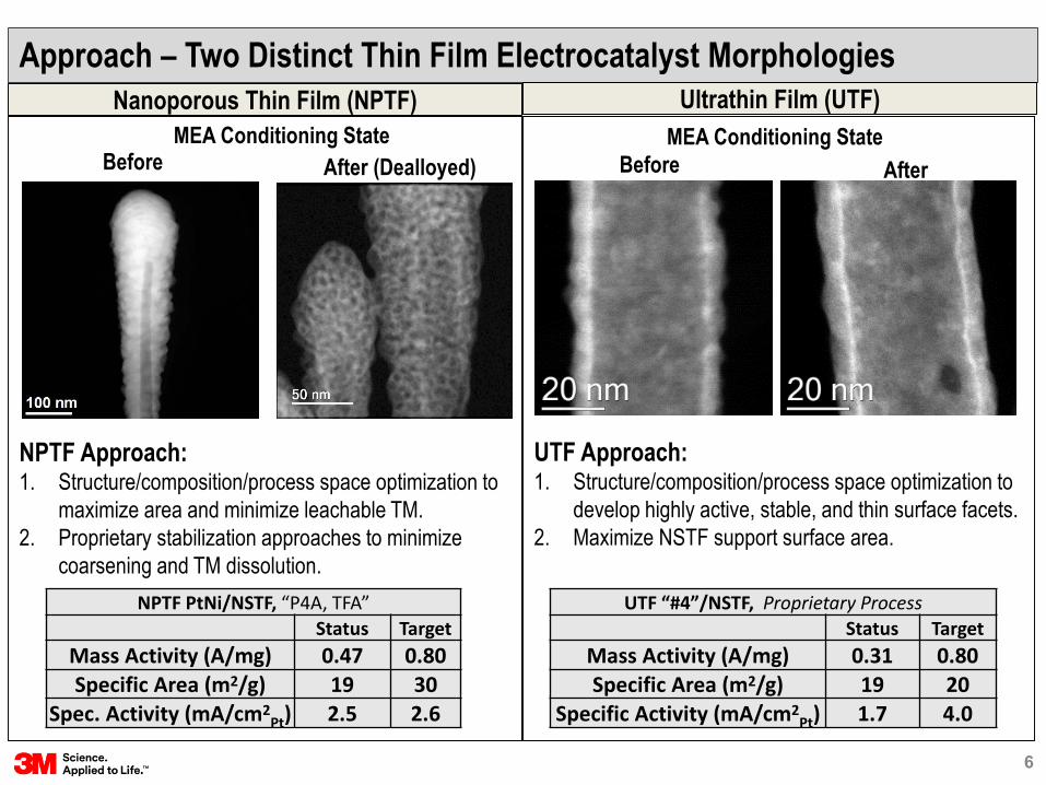
Approach – Two Distinct Thin Film Electrocatalyst MorphologiesNanoporous Thin Film (NPTF)
NPTF Approach:1. Structure/composition/process space optimization to
maximize area and minimize leachable TM.2. Proprietary stabilization approaches to minimize
coarsening and TM dissolution.
UTF Approach:1. Structure/composition/process space optimization to
develop highly active, stable, and thin surface facets.2. Maximize NSTF support surface area.
Ultrathin Film (UTF)
NPTF PtNi/NSTF, “P4A, TFA”Status Target
Mass Activity (A/mg) 0.47 0.80Specific Area (m2/g) 19 30
Spec. Activity (mA/cm2Pt) 2.5 2.6
UTF “#4”/NSTF, Proprietary ProcessStatus Target
Mass Activity (A/mg) 0.31 0.80Specific Area (m2/g) 19 20
Specific Activity (mA/cm2Pt) 1.7 4.0
BeforeMEA Conditioning State MEA Conditioning State
Before AfterAfter (Dealloyed)
6

Approach – Electrocatalyst Modeling
DFTSurface energy calculations of Pt skins on Pt alloys
Kinetic Monte Carlo Alloy surface structure predictions
DFTDescriptor binding energies on optimized surface structures
Kinetic predictions of ORR currents from volcano plots and free energies
1. Atomistic determination of catalyst surface structures
2. Activity predictions of optimized surface structures
3. Model Validation
Activity CharacterizationMEARDEFlow cellStructure/Composition CharacterizationHAADF-STEMSTEM+EDSXAFS / ∆µ-XANESWAXSXRDXRF
Electrocatalyst FabricationPVD DepositionProprietary dealloying and annealing processing
HT Methods When Validated
4. Characterization Feedback for Model Refinement7

Approach – Advanced NSTF Electrode
8
H2/Air Performance Operational Robustness
•! Similar specific activity, specific area as traditional NSTF electrodes.
•! Pt/NSTF adv. electrode has higher activity than heat-treated Pt/C, but transport loss at high J.
•! Similar temperature sensitivity as Pt/C electrodes.
•! Significantly improved over traditional NSTF electrodes.
Per FOA, limited advanced NSTF electrode development will be conducted within the project to enable evaluation of entitlement project electrocatalysts in MEA.
Traditional NSTF Electrode
•! NSTF electrode thickness is sub-micron, enabling high rated power at low Pt loading.
•! Challenges: •! Lower area than Pt/C (higher
contam. sensitivity, slower break-in). •! Lower robustness (flooding);
mitigation by optimized DM and cathode interlayers.
Advanced NSTF Electrode (Early Work)
•! Advanced NSTF electrode has potential to address key challenges with NSTF MEAs, and enables evaluation of entitlement electrocatalyst concepts in MEA.
•! Key Question: Will specific power targets be attainable?

Approach - High Throughput (HT) Electrocatalyst DevelopmentMotivation – Large Variable Space
• Ultimate electrocatalyst performance and durability often has significant interdependencies on composition, structure, and processing conditions.
• Variable space: 5 comp. x 3 structure x 3 process levels = 45 unique electrocatalysts (one binary system)
2
0.2 0.3 0.4 0.50
5
10
15
20
25
Spec
. Are
a (m
2 /gPt)
5 x in PtxNi1-x
0 10 20 3010
12
1416
18
20
0 (111) Grain Size (nm)
S
peci
fic A
rea
(m2 /g
) Pt
NPTF#
1
NPTF#
2
NPTF#
3
NPTF#
4
NPTF#
5
NPTF#
6
NPTF#
7
NPTF#
8
NPTF#
9
NPTF#
10
NPTF#
11
NPTF#
120
1
2
3Dealloy Process Condition A B C D E
Rela
tive
Spec
. Are
a(v
. Pt,
A)
Composition Structure Process
HT Electrocatalyst Fabrication
Deposition - FeasibleDealloying - TBDAnnealing - TBD
HT Electrochem. Characterization
HT Physical Characterization
XRF - ValidatedXRD/WAXS –Feasible/ValidatedXAFS - TBD
Segmented FC - FeasibleMulti-channel flow cells -TBD
Significant first year effort to develop and validate HT methods.
HT Data Management
Custom analysis software – Validated/In ProgressStorage in SQL DB - TBD
9

Pre-Project Background – NPTF PtxNi1-x/NSTF
10
Composition, Structure H2/Air Performance at Low PGM
P4A Annealed
P4A Pt
P4A Annealed
P4A Pt
;%+$,/' W0."A%E234'CA+'"(44#JDBM6-*#NJO&7P# X8L'E'XL6Y'
Q#R#=.SJOD&<# XLMJZEXR6JZ',0AG.#JA:(#N&<O7P# XL6Y'E''B!'
NPTF PtNi Electrocatalyst Durability Insufficient
•! NPTF mass activity and specific area (in MEA) depend strongly on composition and structure induced by annealing.
•! Dealloyed NPTF PtNi can yield high specific power w/ 0.105 mgPGM/cm2
MEA. •! Mass activity
improvement needed to achieve MEA $ power and rated power targets.
•! Substantial losses after 30k DOE Electrocatalyst AST cycles.
1.! Specific area (coarsening) 2.! Specific activity (Ni loss)
0.133 (total)
0.105 (total)
BOL
30k

Pt
NPTF#
1
NPTF#
2
NPTF#
3
NPTF#
4
NPTF#
5
NPTF#
6
NPTF#
7
NPTF#
8
NPTF#
9
NPTF#
10
NPTF#
11
NPTF#
120
1
2
3Dealloy Process Condition A B C D E
Rela
tive
Spec
. Are
a(v
. Pt,
A)
Accomplishments and Progress – NPTF Dealloying OptimizationComposition, Process
• NPTF specific area has strong sensitivity to composition and dealloying process conditions.
• After MEA conditioning, pre-dealloyed NPTF specific area is lower than non-dealloyed.• ~ 50% of liq. values.
• Studies in progress to determine discrepancy source.
Liquid electrolyte
Pre-project work
P1 Pt
, 0.1m
g/cm2
P1 Pt
3Ni7
P1+T
FA Pt
3Ni7
P4A Pt
3Ni7
P4A+T
FA Pt
30Ni70
0
10
20
30
40
Spec
ific
Area
(m2 /g
) ECDA #1 ECDA #2
• Specific area of Pt3Ni7increases 50% (to 30m2/g) after annealing and optimized dealloying.
Structure, Process
Liquid electrolyte
MEA Measurements
NPTF
#3
Non-d
eallo
yed
NPTF
#3
Deall
oy "C
"NP
TF#3
Deall
oy "D
"05
101520
Spe
cific
Are
a(m
2 /gP
GM)
Pre-project and current project work Pre-project work
11
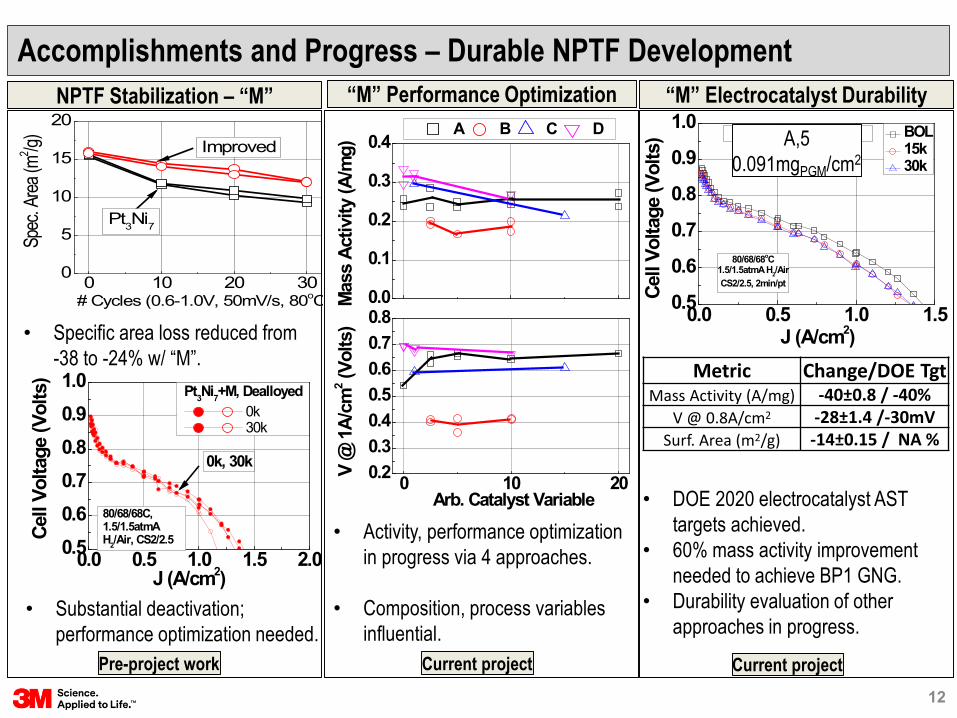
Accomplishments and Progress – Durable NPTF DevelopmentNPTF Stabilization – “M” “M” Performance Optimization
0.0 0.5 1.0 1.50.5
0.6
0.7
0.8
0.9
1.0Stabilzed NPTF, 0.091mgPGM/cm2 BOL
15k 30k
Cell
Volta
ge (V
olts
)
J (A/cm2)
80/68/68oC1.5/1.5atmA H2/AirCS2/2.5, 2min/pt
• Specific area loss reduced from -38 to -24% w/ “M”.
0 10 20 300
5
10
15
20
Improved
Spec
. Area
(m2 /g)
Pt3Ni7
# Cycles (0.6-1.0V, 50mV/s, 80oC
0.0 0.5 1.0 1.5 2.00.50.60.70.80.91.0
Cell
Volta
ge (V
olts
)
0k, 30k
80/68/68C,1.5/1.5atmA H2/Air, CS2/2.5
J (A/cm2)
Pt3Ni7+M, Dealloyed 0k 30k
• Substantial deactivation; performance optimization needed.
0.0
0.1
0.2
0.3
0.4
0 10 200.20.30.40.50.60.70.8
A B C D
Mas
s Ac
tivity
(A/m
g)
Arb. Catalyst Variable
V @
1A/
cm2 (V
olts
)
• Activity, performance optimization in progress via 4 approaches.
• Composition, process variables influential.
“M” Electrocatalyst Durability
• DOE 2020 electrocatalyst AST targets achieved.
• 60% mass activity improvement needed to achieve BP1 GNG.
• Durability evaluation of other approaches in progress.
A,50.091mgPGM/cm2
Pre-project work
Metric Change/DOE TgtMass Activity (A/mg) -40±0.8 / -40%
V @ 0.8A/cm2 -28±1.4 /-30mVSurf. Area (m2/g) -14±0.15 / NA %
Current project Current project12
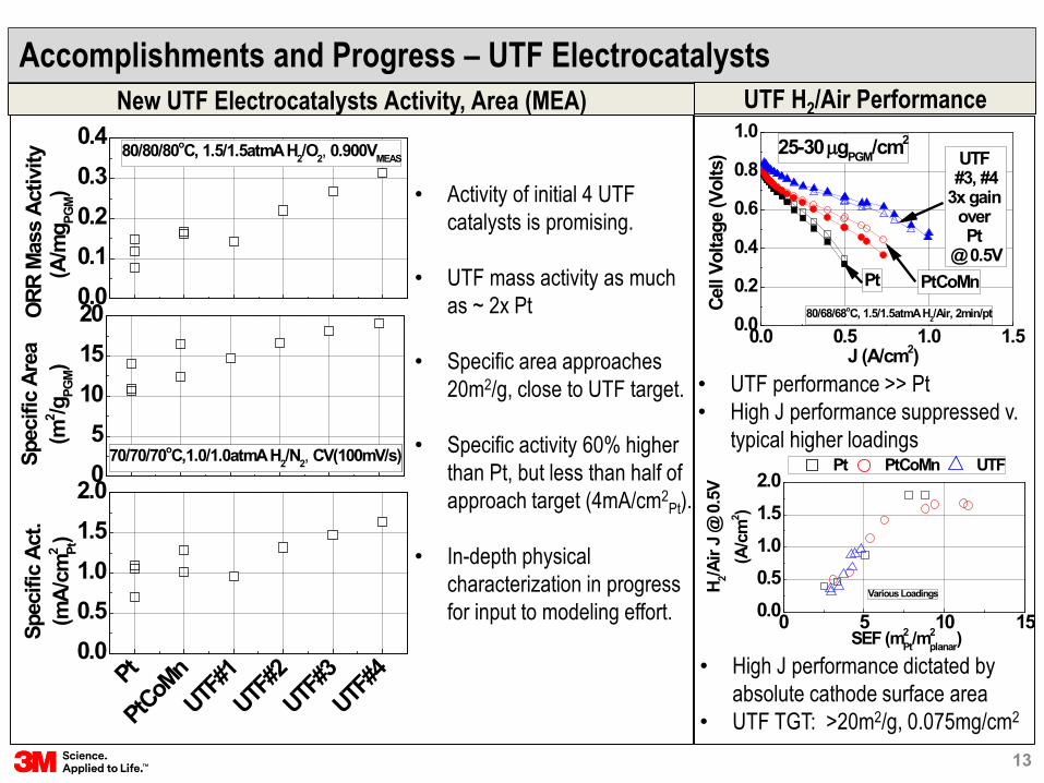
Accomplishments and Progress – UTF ElectrocatalystsNew UTF Electrocatalysts Activity, Area (MEA)
• Activity of initial 4 UTF catalysts is promising.
• UTF mass activity as much as ~ 2x Pt
• Specific area approaches 20m2/g, close to UTF target.
• Specific activity 60% higher than Pt, but less than half of approach target (4mA/cm2
Pt).
• In-depth physical characterization in progress for input to modeling effort.
0.00.10.20.30.4
80/80/80oC, 1.5/1.5atmA H2/O2, 0.900VMEAS
ORR
Mas
s Ac
tivity
(A/m
g PGM)
05
101520
70/70/70oC,1.0/1.0atmA H2/N2, CV(100mV/s)Spec
ific
Area
(m2 /g
PGM)
Pt
PtCoM
nUTF
#1UTF
#2UTF
#3UTF
#40.00.51.01.52.0
70/70/70oC,1.0/1.0atmA H2/N2, CV(100mV/s)
Spec
ific
Act.
(mA/
cm2 Pt)
UTF H2/Air Performance
0 5 10 150.00.51.01.52.0
Pt PtCoMn UTF
H 2/Air
J @
0.5
V(A
/cm
2 )
SEF (m2Pt/m
2planar)
Various Loadings
• UTF performance >> Pt• High J performance suppressed v.
typical higher loadings
• High J performance dictated by absolute cathode surface area
• UTF TGT: >20m2/g, 0.075mg/cm2
0.0 0.5 1.0 1.50.0
0.2
0.4
0.6
0.8
1.0UTF #3, #4
3x gain over Pt
@ 0.5VPtCoMn
80/68/68oC, 1.5/1.5atmA H2/Air, 2min/ptCell
Volta
ge (V
olts
)
J (A/cm2)
Pt
25-30 µgPGM/cm2
13

Accomplishments and Progress – UTF Electrocatalyst Analysis, ModelingUTF STEM Analysis (ORNL)
Before AfterPt
UTF
#3UTF DFT Modeling (Purdue)
• Pt skin surface energy minimization of model UTF
0.92 0.94 0.96 0.98 1.00-0.20-0.18-0.16-0.14-0.12-0.10-0.08
Pt Skin/Pt Bulk Lattice Constant
Ene
rgy
Optimized Pt skin
Pt111 UTF_subsurfA UTF_subsurfB UTF_subsurfC
-0.50.00.51.01.52.02.5 2(H
++e-)+OH*+H
2 O
2H2 O
2( H++e
-) + O*+H2 O
3(H
++e-)+OOH*
4(H++e
-) +O2U=0.90 V
Free
ene
rgy
(eV)
Reaction coordinate• Two possible energy barriers identified for different
model UTF sub-surface compositions• Comparison between experiment and model on-going.
MEA Conditioning State
*
*• Before testing, UTF is somewhat smoother than Pt (still not ideal, atomically smooth surface facets).
• After MEA conditioning, UTF morphology relatively unchanged but significant comp. change likely reduces specific activity.
14

Accomplishments and Progress – High Throughput DevelopmentComposition Analysis of Gradient PtNi Wide Angle Xray Scattering (ANL)
0
40
80
120
0.00.20.40.60.81.0
Ni
Met
al L
oadi
ng(µ
g/cm
2 )
Pt
Position (Arb.)
Pt M
ole
Frac
tion
• PtxNi1-x/NSTF fabricated w/ gradient compositionacross NSTF growth substrate.
• Composition analysis by XRF conducted across gradient w/ 1mm spatial resolution.
• WAXS allowed for relatively rapid measurement of key bulk structural characteristics.
• Lattice constants largely as expected.• Grain sizes larger than determined with similar
homogenous catalysts by XRD
3.653.703.753.803.85
0.3 0.4 0.5 0.6 0.7 0.85
10
15
Vegard'sLaw
Latti
ce C
onst
. (An
g.)
WAXS
Grai
n Si
ze (n
m)
Pt Mole Fraction
15

0
20
40
60
0.500.751.001.251.50
0.70
0.75
0.80
0.85
0.90
0.2 0.3 0.50.01 0.1
0 2 4 6 8 100.0
0.1
0.2
0 2 4 6 8 10
0
2
4
6
8
10
y: Net C
athode Flow D
irection→
0.5000
0.6250
0.7500
0.8750
1.000
1.125
1.250
1.375
1.500
JNorm
Load
ing
(µg/
cm2 )
J NO
RM
MEAN JMeas(x,y) MEAN JMeas(x,0.5) MEAN JMeas(x,10.5)
Current Density (A/cm2)
80oC, 100/100%RH, 2.5/2.5atmA 696/1657SCCM, H2/O2
Cel
l Vol
tage
(Vol
ts)
Analysis pointJMEAN:0.1A/cm2
Mas
s A
ct.
(A/m
g)
Corrected to 0.900VIR-Free , pO2=1atm
Accomplishments and Progress – High Throughput DevelopmentSegmented Cell MEA Activity of Loading-Gradient Pt/NSTF Electrode
• Successfully evaluated mass activity of gradient NSTFelectrode MEA in 121 segment, 50cm2 test cell.• Pt load gradient: 48→22µg/cm2
• J gradient consistent w/ loading gradient• Mass activity @ 0.900VIR-FREE similar to homogenous
catalysts.
• Application to gradient alloy electrocatalyst in progress.
16
Collaborations
• 3M - Electrocatalyst Fabrication and Characterization, Electrode and MEA Integration,HT Development• Energy Components Program: A.Steinbach (PI), A. Hester, C. Duru, S. Luopa, A. Haug,
J. Abulu, A. Komlev, K. Lewinski, M. Kuznia, and I. Davy.• Corporate Analytical Laboratory: J. Bender, M. Stephens, M. Brostrom, A. Gharachorlou
• Johns Hopkins University – Dealloying Optimization, kMC Modeling, HT Development• J. Erlebacher (PI), L. Siddique
• Purdue University – DFT Modeling of Electrocatalyst Activity, Durability• J. Greeley (PI), Z. Zeng
• Oak Ridge National Laboratory – Structure/Composition Analysis• D. Cullen (PI)
• Argonne National Laboratory – XAFS and HT Development• D. Myers (PI), J. Kropf
• FC-PAD Consortium• MEAs to be provided annually.
17

Barriers
1. Significantly improved electrocatalysts will require optimization of large composition/process space.
2. Electrocatalyst AST durability of UTF electrocatalysts is not known; may be insufficient to achieve DOE and project targets.
3. Minimum stable UTF electrocatalyst thickness on support, fabricated with scalable-processes, is not known.
18
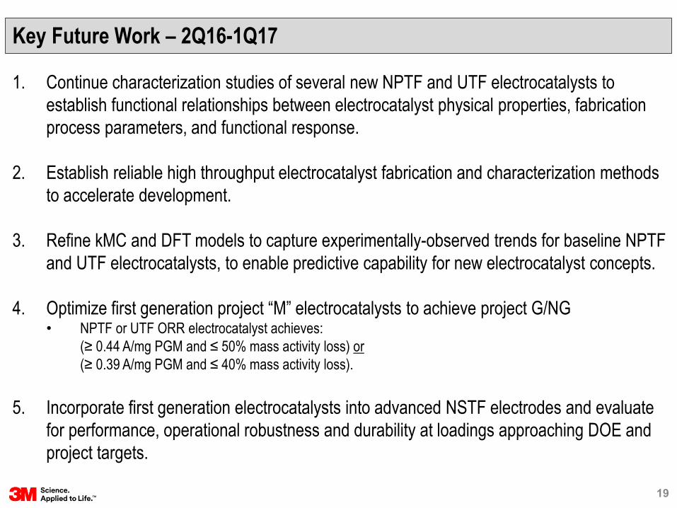
Key Future Work – 2Q16-1Q17
1. Continue characterization studies of several new NPTF and UTF electrocatalysts to establish functional relationships between electrocatalyst physical properties, fabrication process parameters, and functional response.
2. Establish reliable high throughput electrocatalyst fabrication and characterization methods to accelerate development.
3. Refine kMC and DFT models to capture experimentally-observed trends for baseline NPTF and UTF electrocatalysts, to enable predictive capability for new electrocatalyst concepts.
4. Optimize first generation project “M” electrocatalysts to achieve project G/NG• NPTF or UTF ORR electrocatalyst achieves:
(≥ 0.44 A/mg PGM and ≤ 50% mass activity loss) or(≥ 0.39 A/mg PGM and ≤ 40% mass activity loss).
5. Incorporate first generation electrocatalysts into advanced NSTF electrodes and evaluate for performance, operational robustness and durability at loadings approaching DOE and project targets.
19

Response to Reviewers’ Comments
• This project has not yet been reviewed.
20

Summary
• NSTF ORR electrocatalyst development is based on two distinct thin film morphologies.1. Nanoporous thin film
• Current status (in MEA): 0.47A/mg, 19m2/g, 0.091mgPGM/cm2
• Sensitive to composition, structure, and dealloying process conditions2. Ultrathin film
• Current status (in MEA): 0.31A/mg, 19m2/g, 0.025mgPGM/cm2
• H2/Air performance is transport limited; need 2x higher absolute area.• Durability assessments initiated
• Stabilization approach (“M”) has enabled electrocatalyst which achieves DOE 2020 durability target but activity low; further optimization in progress.
• High throughput electrocatalyst development has good prospects for significantly accelerating project development timeline.1. HT Fabrication
• Deposition demonstrated2. HT Electrochemical Characterization
• Segmented cell promising.3. HT Composition/Structure Characterization
• Bulk composition and structure analysis demonstrated.
21

Technical Backup Slides
22

“M” Performance (BOC Format)
• “M” integrated into BOC MEA format (FC104) and evaluated for performance and operational robustness.
• Compared to 3M 2015(Sept.) BOC MEA (FC104), first “M” BOC MEA has:• Lower BOL mass activity (0.28 v. 0.39A/mg)• Lower rated and specific power (5.7 v. 6.8 kW/g)• Similar/improved operational robustness
“M” Robustness (BOC Format)
0.0 0.5 1.0 1.5 2.00.50.60.70.80.91.0
NPTF "M" Cathode0.13mgPGM/cm2
90oC Cell, GDS(2min/pt)1.5/1.5atmA (OUT) H2/Air, CS2/2.5
J>0.4: 84/84C DP. J < 0.4: 68/68C DP
Cell
V (V
olts
)
J (A/cm2)
2015(Sept.) BOC MEA0.131mgPGM/cm2
MEA
0 20 40 60 80 100-0.2
0.0
0.2
0.4
0.6
0.8"M"
2015 (Sept.) BOC MEA
RobustnessTargets
2015 (Mar.) BOC MEA
Min
imum
Cel
l V D
urin
gLo
ad T
rans
ient
(Vol
ts)
Cell Temperature (oC)
2013 BaselineMEA
150/150kPaA CS2/2 H2/Air. 1A/cm2
60-80oC: 100%RH 30-40oC: 0% RH
Both MEAs include identical “X3” anode GDL, “B” cathode interlayer (16µg/cm2 Pt/C), 3M-S 725EW 14µ PEM, and FF2 from FC104.Loadings are total MEA (anode, cathode, and interlayer).
Backup Slide – “M” Best of Class MEA
23

Backup Slide – HT MEA Evaluation of NPTF PtxNi1-x (First Trial)
0.2
0.3
0.4
0.5
0.0
0.1
0.2
0.3
0.4
0.5
2 4 6 8 10
2
4
6
8
10
x: Decreasing Pt Mole Fraction→
y: Net C
athode Flow D
irection→
0.000
0.05000
0.1000
0.1500
0.2000
0.2500
0.3000
0.3500
0.4000
0.4400
JMassNorm
x va
riabl
ePt
Mol
e Fr
actio
n
80oC, 100/100%RH, 1.5/1.5atmA H2/O2
696/414SCCM, JMEAN:0.02A/cm2
Mea
n JM
ass
A/m
g)
0.2
0.3
0.4
0.5
0 2 4 6 8 100
5
10
15
20
2 4 6 8 10
2
4
6
8
10
x: Decreasing Pt Fraction→
y: Net C
athode Flow D
irection→10.00
11.00
12.00
13.00
14.00
15.00
16.00
17.00
18.00
25.00
Spec. Area(m2/g)
70oC, 100/100%RH, 1/1atmA H2/N2, 800/1800SCCM, Ox Wave
x va
riabl
ePt
Mol
e Fr
actio
n
Segcell
Spec
ific
Are
a(m
2 /g)
Homogenous, 50cm2
MEA
• Annealed NPTF PtNi in segmented cell does not show expected 2x transition in activity and area at Pt3Ni7• Segmented cell “peak” approximately at right composition, but response is very muted.• Diagnostic work in progress.
Mass Activity Specific Area
24

Backup Slide – WAXS of Gradient PtNi ElectrocatalystMeasured WAXS Spectra v. Position Peak Fitting
25

Backup Slide – Adv. Electrode Performance, Robustness, Activity
A. At similar loading, Pt/NSTF in advanced electrode yields higher kinetic but reduced transport performance.
B. Activity, area of Pt/NSTF and dealloyed NPTF PtNi/NSTF advanced electrodes compared to HT Pt/C; similar to traditional NSTF electrodes; suggests little/no activity penalty in MEA electrode.
C. Operational robustness (temperature sensitivity) of adv. NSTF electrode similar to Pt/C and traditional NSTF electrodes w/ optimized anode DM and cathode IL; significantly improved over traditional NSTF w/o optimized ad-layers.
0.0 0.5 1.0 1.5 2.00.5
0.6
0.7
0.8
0.9
1.0
0.00.51.01.52.02.5
35 40 45 50 55 60 650.0
0.2
0.4
0.6
0.8
1.0
010203040
Pt/C (HT) Pt/NSTFAdv. Elec.
PtNi/NSTFAdv. Elec.
0.0
0.2
0.4
0.6
UTF PtNi Trad. Elec.
(Model)
UTF PtNi Trad. Elec.
(Exp.)
UTF Pt Adv. Elec.(Model)
UTF Pt Adv. Elec.
(Exp.)
010203040
Pt/C (HT), 0.25mgPt/cm2 Pt/NSTF, 0.28mgPt/cm2, Adv. Electrode
Cel
l Vol
tage
(Vol
ts)
J (A/cm2)
70/70/70C, CS1.7/2.5, 0/0psigGDS(1min/pt)
C
Spec
. Act
ivity
(m
A/cm
2 Pt)
A
0/0% RH, CS2.5/3.4, 0/0psig1A/cm2
Pt/C, Std. Anode and Cathode GDL Pt/NSTF, Adv. Elec., Std. Anode and Cathode GDL PtCoMn/NSTF, Trad. Elec., Std. Anode and Cathode GDL PtCoMn/NSTF, Trad. Elec., BOC Anode GDL and Cathode IL
Cel
l Vol
tage
(Vol
ts)
Cell Temp (°C)
Spec
ific
Area
(m
2 /gPt)
B
Mas
s Ac
tivity
(A
/mg Pt
)
D
Spec
ific
Area
(m
2 /gPt) Standard Supports
26