Highlight This Line And Type Title Here (Initial Cap, 22...
65
Feasibility Study Beneficial Reuse of Dredged Materials for Tidal Marsh Restoration and Sea Level Rise Adaptation in Humboldt Bay, California Prepared for: Humboldt Bay Harbor, Recreation, and Conservation District Consulting Engineers & Geologists, Inc. 812 W. Wabash Ave. Eureka, CA 95501-2138 707-441-8855 980 7th Street Arcata, CA 95521 707-845-6877 1225 Central Avenue P.O. Box 2515 McKinleyville, CA 95519 707-839-2195 July 2015 013153
Transcript of Highlight This Line And Type Title Here (Initial Cap, 22...

Feasibility Study Beneficial Reuse of Dredged Materials for Tidal Marsh Restoration and Sea Level Rise Adaptation in Humboldt Bay, California
Prepared for:
Humboldt Bay Harbor, Recreation, and Conservation District
Consulting Engineers
& Geologists, Inc. 812 W. Wabash Ave.
Eureka, CA 95501-2138 707-441-8855
980 7th Street
Arcata, CA 95521 707-845-6877
1225 Central Avenue
P.O. Box 2515 McKinleyville, CA 95519
707-839-2195
July 2015
013153


\\Eureka\Projects\2013\013153-DredgeReuse\PUBS\rpts\20150714-FinalBeneficialReuseFeasibilityStudy.docx i
Table of Contents Page
List of Illustrations .......................................................................................................................................... iii
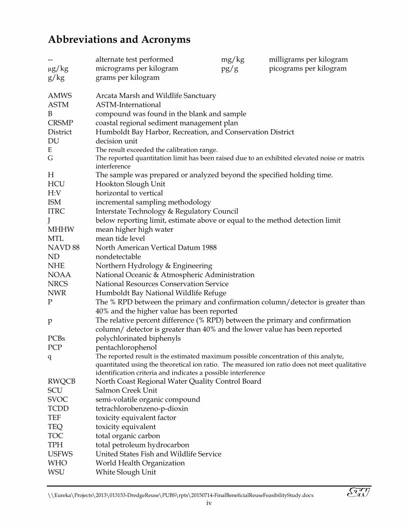
Abbreviations and Acronyms ....................................................................................................................... iv
1.0 Introduction .......................................................................................................................................... 1 1.1 Tidal Wetland Restoration ..................................................................................................... 1 1.2 Humboldt Bay Dredged Sediment Management ............................................................... 2 1.3 Stakeholder Involvement ....................................................................................................... 3 1.4 Existing Studies and Reports ................................................................................................. 4
1.4.1 City of Eureka and Humboldt Bay Harbor, Recreation and Conservation District Sediment Sampling Analysis ............................................. 4
1.4.2 Coastal Regional Sediment Management Plan, Eureka Littoral Cell, CA ......... 7 1.4.3 Humboldt Bay Shoreline Inventory, Mapping and Sea Level Rise
Vulnerability Assessment ......................................................................................... 8 1.4.4 Humboldt Bay: Sea Level Rise, Hydrodynamic Modeling and
Vulnerability Mapping .............................................................................................. 8
2.0 Tidal Wetland Restoration and Sea Level Rise Adaptation ........................................................... 9 2.1 Historical Shoreline Conditions of Humboldt Bay ............................................................ 9 2.2 Shoreline Sea Level Rise Vulnerability Assessment Rating ............................................ 10 2.3 Beneficial Reuses of Sediments from Small-scale Dredging ........................................... 10
2.3.1 Tidal Wetland Restoration ...................................................................................... 11 2.3.2 Response to Climate Change: Sea Level Rise ....................................................... 13
3.0 Pilot Project Sites Selection ............................................................................................................... 18 3.1 Pilot Study Site Selection Procedure .................................................................................. 18 3.2 Pilot Study Sites ..................................................................................................................... 18
3.2.1 Pilot Project Site 1: Humboldt Bay National Wildlife Refuge White Slough Unit ............................................................................................................... 19
3.2.2 Pilot Project Site 2: Humboldt Bay NWR Salmon Creek Unit ........................... 19 3.2.3 Pilot Project Site 3: City of Arcata’s Living Shoreline ......................................... 20 3.2.4 Pilot Project Site 4: Humboldt Bay NWR Hookton Slough Unit ....................... 20
4.0 Pilot Project Sites Feasibility Assessment ....................................................................................... 20 4.1 Physical Considerations ....................................................................................................... 20 4.2 Environmental Considerations ........................................................................................... 21
4.2.1 Chemical Considerations ........................................................................................ 21 4.2.2 Biological Considerations ....................................................................................... 21 4.2.3 Cultural Considerations .......................................................................................... 22 4.2.4 Climate Change Considerations ............................................................................ 22
4.3 Economic Considerations .................................................................................................... 22 4.3.1 Planning and Permitting ......................................................................................... 22 4.3.2 Engineering Designs ................................................................................................ 23 4.3.3 Implementation and Construction ........................................................................ 23
5.0 Sediment Quality Analyses .............................................................................................................. 23 5.1 Incremental Sampling Methodology.................................................................................. 23 5.2 Field Program ........................................................................................................................ 24

Table of Contents, Continued Page
\\Eureka\Projects\2013\013153-DredgeReuse\PUBS\rpts\20150714-FinalBeneficialReuseFeasibilityStudy.docx ii
5.3 Laboratory Analyses ............................................................................................................. 24 5.3.1 Physical Characteristics ........................................................................................... 24 5.3.2 Chemical Constituents ............................................................................................ 25
5.4 Preliminary Comparison of Laboratory Results ............................................................... 30 5.4.1 Texture ....................................................................................................................... 30 5.4.2 Total Organic Carbon .............................................................................................. 30 5.4.3 Metals ........................................................................................................................ 31 5.4.4 Polychlorinated Biphenyls ...................................................................................... 32 5.4.5 Semi-Volatile Organics ............................................................................................ 32 5.4.6 Organochloride Pesticides ...................................................................................... 32 5.4.7 Herbicides ................................................................................................................. 33 5.4.8 Dioxins and Furans .................................................................................................. 33
6.0 Preferred Pilot Projects ...................................................................................................................... 33 6.1 Humboldt Bay National Wildlife Refuge Salmon Creek Unit Conceptual
Design Summary ................................................................................................................... 33 6.1.1 Site Conditions ......................................................................................................... 33 6.1.2 Conceptual Design Features ................................................................................... 34
6.2 Humboldt Bay National Wildlife Refuge Hookton Slough Unit Conceptual Design Summary ................................................................................................................... 35 6.2.1 Site Conditions ......................................................................................................... 35 6.2.2 Conceptual Design Features ................................................................................... 35
7.0 References ........................................................................................................................................... 36 Appendices
A. Advisory Committee and Comments B. Potential Pilot Projects C. Laboratory Analyses D. Preferred Pilot Projects Conceptual Designs

\\Eureka\Projects\2013\013153-DredgeReuse\PUBS\rpts\20150714-FinalBeneficialReuseFeasibilityStudy.docx iii
List of Illustrations Figures Follows Page
1. Location Map ........................................................................................................................... 1 2. Dredged Material Processing Facilities ............................................................................... 3 3. The extent of historical salt Marsh within the 1870 tidal shoreline at Eureka
Slough ....................................................................................................................... On Page 94. The tidal shoreline at the Highway 101 corridor between Bracut and California
Redwood Company .............................................................................................. On Page 115. Potential living shoreline sites along the exposed perimeters of the City of
Arcata’s Wastewater Treatment Facility, and existing living shorelines to the west and south ...................................................................................................... On Page 14
6. Diked former tidelands (Eureka Slough and Freshwater Creek) that are being used for agricultural practices dusceptible to rising groundwater with sea level rise3 that ................................................................................................................ On Page 15
7. Existing salt marsh area along Highway 255 in a fetch shadow that is physically constrained from migrating inland with sea level rise ................. On Page 16
8. Low elevation of the Elk River Slough spit affords protection to the City of Eureka’s Wastewater Treatment Plant ............................................................... On Page 17
9. Pilot Study Site Location Map ............................................................................................. 19 10. White Slough Unit Field Sampling Plan ............................................................................ 23 11. Sediment Laboratory Analysis Results: Texture. ............................................................. 23 12. Sediment Laboratory Analysis Results: Total Organic Carbon. ..................................... 23 13. Sediment Laboratory Analysis Results: Metals. ............................................... On Page 25 14. Sediment Laboratory Analysis Results: Total Mercury. .................................. On Page 30 15. Sediment Laboratory Analysis Results: Metals. ............................................... On Page 31 16. Sediment Laboratory Analysis Results: Total Mercury .................................. On Page 32
Photo 1. Diked and reclaimed tidelands along White Slough ....................................... On Page 12 Tables On Page
1. 2005 Laboratory Analyses Results of Small Docks and Marinas Sediment Physical Composition and Chemical Constituents1 .......................................................................... 5
2. 2005 Laboratory Analyses Results of Dioxin TEQ1 and PCP2 for Small Docks and Marinas Sediments3 ................................................................................................................ 7
3. Physical Character of Pilot Study Site Soils ....................................................................... 244. Laboratory Analyses Results of Pilot Study Sites Sediment Chemical Constituents .. 26
DRAFT
\\Eureka\Projects\2013\013153-DredgeReuse\PUBS\rpts\20150714-FinalBeneficialReuseFeasibilityStudy.docx iv
Abbreviations and Acronyms -- alternate test performed µg/kg micrograms per kilogram g/kg grams per kilogram
mg/kg milligrams per kilogram pg/g picograms per kilogram
AMWS Arcata Marsh and Wildlife Sanctuary ASTM ASTM-International B compound was found in the blank and sample CRSMP coastal regional sediment management plan District Humboldt Bay Harbor, Recreation, and Conservation District DU decision unit E The result exceeded the calibration range. G The reported quantitation limit has been raised due to an exhibited elevated noise or matrix
interference H The sample was prepared or analyzed beyond the specified holding time. HCU Hookton Slough Unit H:V horizontal to vertical ISM incremental sampling methodology ITRC Interstate Technology & Regulatory Council J below reporting limit, estimate above or equal to the method detection limit MHHW mean higher high water MTL mean tide level NAVD 88 North American Vertical Datum 1988 ND nondetectable NHE Northern Hydrology & Engineering NOAA National Oceanic & Atmospheric Administration NRCS National Resources Conservation Service NWR Humboldt Bay National Wildlife Refuge P The % RPD between the primary and confirmation column/detector is greater than
40% and the higher value has been reported p The relative percent difference (% RPD) between the primary and confirmation
column/ detector is greater than 40% and the lower value has been reported PCBs polychlorinated biphenyls PCP pentachlorophenol q The reported result is the estimated maximum possible concentration of this analyte,
quantitated using the theoretical ion ratio. The measured ion ratio does not meet qualitative identification criteria and indicates a possible interference
RWQCB North Coast Regional Water Quality Control Board SCU Salmon Creek Unit SVOC semi-volatile organic compound TCDD tetrachlorobenzeno-p-dioxin TEF toxicity equivalent factor TEQ toxicity equivalent TOC total organic carbon TPH total petroleum hydrocarbon USFWS United States Fish and Wildlife Service WHO World Health Organization WSU White Slough Unit

\\Eureka\Projects\2013\013153-DredgeReuse\PUBS\rpts\20150714-FinalBeneficialReuseFeasibilityStudy.docx 1
1.0 Introduction Humboldt Bay is a multi-basin, tidally driven coastal lagoon (Costa, 1982), located in northern California, along the shores of Arcata and Eureka (Figure 1). It is the only deep-water port between San Francisco Bay and Coos Bay, Oregon and has been governed under the jurisdiction of the Humboldt Bay Harbor, Recreation, and Conservation District (District) since 1973. The District has recently acquired a cutter-head suction dredge to perform the bay’s small-scale dredging, to remove the fine sediments that have accumulated beneath the marinas and docks (Figure 1). Dredged material has been recognized by the State Coastal Conservancy as a resource to assist in the restoration of tidal wetlands in the bay, based on similar projects that have been implemented at the Sonoma Baylands and Hamilton Army Airfield Wetlands projects, both located along San Pablo Bay, in Marin County, California. In other regions, dredged sediments have been used beneficially for beach and dune nourishment, wetland restoration, erosion control, to create safer waterfront access, and to enhance recreational opportunities (Moffat and Nichol, 2013). This study evaluates the feasibility of Humboldt Bay dredged material reuse for two purposes: tidal marsh restoration and responding to climate change, specifically to impacts from sea level rise. This work contributes to three major efforts in Humboldt Bay:
1) tidal wetland restoration planning and design, 2) facilitating dredging projects by identifying reuse locations for dredged sediments, and 3) minimizing sea level rise impacts to areas adjacent to the bay.
This report evaluates dredged sediment reuse options for tidal wetland restoration at three pilot study sites and presents a conceptual design for implementation of two tidal wetland restoration sites. In preparing this study, we drew relevant information from publications; collected data; and convened two meetings with an advisory committee comprised of project stakeholders to provide professional input to and peer-review of the initial process and the draft feasibility study. This report considers the physical, environmental, and economic issues that need to be assessed to determine the feasibility of using dredged material for tidal wetland restoration. This report is not intended to provide a final determination on these issues; rather, it is intended to provide a basis to proceed with planning, design, and implementation. Project feasibility is limited to the pilot study sites and does not evaluate the planning and permitting for dredging, dewatering, processing, staging, or transporting dredged material. All reported elevations are referenced to the North American Vertical Datum of 1988 (NAVD 88). 1.1 Tidal Wetland Restoration For the purposes of this study, the goal of restoring tidal wetlands is to create intertidal and subtidal habitats, including tidal marsh, tidal channels, and mudflat. Tidal marsh habitat, as classified by Cowardin et al. (1979), occurs in the estuarine system, intertidal subsystem, emergent wetland class, and persistent subclass with a regularly or irregularly flooded water regime. The water chemistry is mixohaline and the soils are mineral or organic. Restoring tidal wetlands will offer production and habitat for numerous aquatic organisms and wildlife species. Functionally, restoring tidal wetlands will assist in flood management and abate pollution.

N
FigureConsulting Engineers
& Geologists, Inc.
\\Eu
reka
\Pro
ject
s\20
13\0
1315
3-D
redg
eReu
se\D
wgs
,SA
VED
:4/2
7/20
151:
52PM
ND
OW
NEY
,PLO
TTED
:4/2
7/20
151:
52PM
,NA
THA
ND
OW
NEY
Humboldt Bay HarborRecreation and Conservation District
Humboldt Bay Dredge Sediment Reuse
Site Location Map
1SHN 013153
April 2015 013153-LCTN

\\Eureka\Projects\2013\013153-DredgeReuse\PUBS\rpts\20150714-FinalBeneficialReuseFeasibilityStudy.docx 2
Given an adequate fine sediment supply, tidal wetlands are expected to keep pace with relative sea level rise (Cahoon et al., 2006). Sediment is supplied to the bay from drainage basin runoff, oceanic input, and minimally by biological activity (Barnhart et al., 1992). Tributary runoff is limited to small-scale watersheds: Jacoby Creek and Freshwater Creek in Arcata (North) Bay, Elk River in Entrance Bay, and Salmon Creek in South Bay. Oceanic input, likely derived from nearby large river systems (Eel River and Mad River) that are transported in to the bay by near-shore currents during flood tides and is estimated to provide the greatest source of sediment to Humboldt Bay (Barnhart et al., 1992). Since the 1880s, earthen dikes have been built to drain Humboldt Bay’s tidelands, primarily for agriculture. Today, most of Humboldt Bay’s historical salt marshes are located landward of dikes, inhibiting both tidal inundation and sediment exchange. Without sediment supply from the bay, these historical tidelands have subsided due to compaction from loss of tidal inundation, exposure to oxidation, and the resulting decomposition and shrinkage of peat; and to local vertical land motion, which in Humboldt Bay is trending downward, relative to mean sea level with the greatest elevation change in South Bay (Anderson, 2015). Restored tidal wetlands buffer climate change by sequestering carbon from the atmosphere (Chmura et al., 2003), and have the potential to store it for more than hundreds and possibly thousands of years. Average rates of carbon sequestration in San Francisco Bay tidal marshes measured using 210Pb dating were 79 grams of carbon per square meter, annually (Calloway et al., 2012). The large capacity of salt marshes to store carbon is due to a unique condition of subsidence under their own weight, increasing their bulk density, and allowing sediment accretion to occur continuously through the process of tidal inundation. Unlike freshwater wetlands and peatlands, the soil chemistry of tidal salt marshes reduces the amount of methane released as carbon is sequestered (Chmura et al., 2003). Tidal marshes typically maintain high rates of productivity and slow rates of organic matter decomposition because of the wet and anaerobic environment. From a climate change mitigation perspective, restoring tidal salt marsh is one of the most effective measures of sequestering carbon from the atmosphere. 1.2 Humboldt Bay Dredged Sediment Management Federal, district, and private navigation channels are dredged within Humboldt Bay to maintain adequate channel depth for deep-draft vessels. The United States Army Corps of Engineers performs most of the dredging, which accounts for approximately 1.2 million cubic yards annually. The District is responsible for dredging the interior, non-federal channels within its jurisdiction, which has accounted for approximately 200,000 cubic yards per event, on an 8- to 10- year cycle, for an estimated 20-25,000 cubic yards per year. The District recently purchased a cutter-head dredge and now has the capability to maintain the small docks and marinas in Humboldt Bay annually. The cutter-suction dredge produces slurry of sediment-laden water that can be pumped through pipes to a dewatering/settling area. The dewatering area is planned to be either a permitted sediment processing facility or a beneficial reuse project site where the material can be dewatered and processed. Another option is to pump the dredged material to a beach to be washed to the ocean during high tides. Although the latter option was implemented during the past two dredging cycles, it is the least favorable among several of the governing regulatory agencies and local environmental advocacy groups.

\\eureka\projects\2013\013153-DredgeReuse\PUBS\rpts\20150714-FinalBeneficialReuseFeasibilityStudy.docx 3
The District plans to establish up to three dredged material processing facilities for staging, dewatering, and temporary storage, located at Samoa and Fields Landing (Figure 2). In North Bay, there is an opportunity for two processing facilities in Samoa. One is located near the intersection of Highway 255 and Samoa Boulevard on approximately 30 acres, and consists of two dewatering and storage cells (approximately 13 acres) that are filled with dredged sediments from historical dredging events. These sediments will need to be characterized prior to relocating the fill at a permanent site. The second site is located at the former Louisiana Pacific pulp mill recently purchased by the District. This site could potentially be used for dewatering and stockpiling of dredged sediments and also has an ocean outfall pipe that could be used to discharge the water. In South Bay, the District owns property in Fields Landing, which offers approximately 4.5 acres of flat, potentially useable area with no containment. The temporary construction of a dewatering and processing area may use Geotube® dewatering technology to elutriate sediment from dredged bay water. The District would likely need to sample the dredge wastewater to ensure that it meets requirements for discharge to an existing groundwater table, the bay, or the ocean. The permitting involved with getting these processing facilities on-line will be the primary hurdle for their use. 1.3 Stakeholder Involvement An advisory committee was formed to provide input on the project process and stakeholder’s opinions of where a project of this type should be implemented. The advisory committee was comprised of representatives from local government agencies and tribes; local, state, and federal regulatory agencies; public land managers; non-profit environmental advocacy groups; and other known interested parties. Included in Appendix A is a list of the individuals that participated in the advisory committee. The first of two advisory committee meetings was convened on January 10, 2014, to introduce the project scope, to have an opportunity for the group to comment on the project outline, and allow the governing agencies to identify project limitations. Written comments were requested to guide the project team and the District on the issues and level of project support. Four written comments were received and are presented in Appendix A. In general, the projects received support from the advisory committee (both written and verbally) with a preference for the restoration of reclaimed tidelands, landward of the existing dikes, by way of dike removal or breaching. A more controversial option, but acceptable to the regulatory agencies, involved projects bay-side of the existing dikes to protect existing infrastructure from sea level rise impacts, such as, a “living shoreline.” There was concern that constructing living shorelines bay-side of the existing dikes would not be restoration per se, but rather land conversion from mudflat to salt marsh habitat with a net loss of mudflat in the bay. Other comments included concern regarding the levels of copper, mercury (as methyl-mercury), and radionuclides at the sediment source and placement sites. Metals were tested at each pilot study site, including copper and total mercury, and compared to the most recent available dredge material laboratory results (Pacific Associates, 2005). Radionuclides were not tested at any of the pilot study sites. It is assumed that the only potential source of radionuclides from dredged material in Humboldt Bay would be derived from areas adjacent to the decommissioned nuclear power plant at the Humboldt Bay Power Plant in King Salmon, including Fisherman’s Channel. Use of the dredged material from Fisherman’s Channel is not discussed in the project; however, planning and permitting the dredging of Fisherman’s Channel by Pacific Gas & Electric Company is currently underway, as a separate project.

N
FigureConsulting Engineers
& Geologists, Inc.
\\Eu
reka
\Pro
ject
s\20
13\0
1315
3-D
redg
eReu
se\D
wgs
,SA
VED
:7/1
5/20
155:
59PM
ND
OW
NEY
,PLO
TTED
:7/1
5/20
155:
59PM
,NA
THA
ND
OW
NEY
Humboldt Bay HarborRecreation and Conservation District
Humboldt Bay Dredge Sediment Reuse
HBHRCD Dredged SedimentProcessing Facilities Map
2SHN 013153
July 2015 013153-PRCS-FCLTY

\\Eureka\Projects\2013\013153-DredgeReuse\PUBS\rpts\20150714-FinalBeneficialReuseFeasibilityStudy.docx 4
A final advisory committee meeting took place on December 17, 2014, to present the draft feasibility study and provide the opportunity for the group to comment before the study was finalized. No comments were received. 1.4 Existing Studies and Reports All of the previously documented dredged sediment characterization studies for the Humboldt Bay small marinas and docks were reviewed, and data resulting from the most recent dredge sediment characterization study: City of Eureka and Humboldt Bay Harbor, Recreation and Conservation District Sediment Sampling Analysis (Pacific Affiliates, 2005) is presented. Also discussed are the Coastal Regional Sediment Management Plan, Eureka Littoral Cell, CA (Moffat and Nichol, 2013), the Humboldt Bay Shoreline Inventory, Mapping and Sea Level Rise Vulnerability Assessment (Laird, 2013), and the Humboldt Bay: Sea Level Rise, Hydrodynamic Modeling and Vulnerability Mapping (Anderson, 2015). Several reports and permits from other coastal areas in California and Oregon were reviewed for reference about using dredged sediments to construct tidal wetlands. 1.4.1 City of Eureka and Humboldt Bay Harbor, Recreation and Conservation District
Sediment Sampling Analysis In 2005, the District contracted a study to characterize the in-place quality of the sediment proposed for dredging to facilitate permitting (Pacific Affiliates, 2005). The project study locations and physical and chemical characteristics are summarized in Tables 1 and 2.

\\Eureka\Projects\2013\013153-DredgeReuse\PUBS\rpts\20150714-FinalBeneficialReuseFeasibilityStudy.docx 5
Table 1 2005 Laboratory Analyses Results of Small Docks and Marinas Sediment Physical Composition and Chemical Constituents1
Beneficial Reuse of Dredged Materials Feasibility Study Humboldt Bay Harbor, Recreation, and Conservation District
Ana
lyte
Uni
ts
Doc
k B
#A-(1
,2,3
,4)
Smal
l Boa
t Ba
sin
#A
-(1,2
,3,4
)
Smal
l Boa
t Ba
sin
#B
-(1,2
,3,4
)
Com
mer
cial
St
reet
Doc
k
#A-(1
,2)
Coa
st S
eafo
ods
#A
-(1,2
,3)
Fish
erm
an's
Doc
k Te
rmin
al
#A-(1
,2,3
,4)
F St
Doc
k
I St D
ock
#A
-(1,2
,3,4
)
Com
posi
te o
f J
St D
ock,
Ado
rni
Cen
ter,
Bonn
ie
Goo
l & S
amoa
Br
idge
#10
Woo
dley
Isla
nd
#A-(1
,2,3
.4)
Woo
dley
Isla
nd
#B-(1
,2,3
.4)
Woo
dley
Isla
nd
#C-(1
,2,3
.4)
Woo
dley
Isla
nd
#D-(1
,2,3
,4)
Percent Solids % dry wt. 55 52 75 62 62 64 61 59 59 60 57 56 53 Percent Sand % 18.5 24.7 36.8 18.1 16.1 14.1 8.9 5.5 12.5 9 7.5 3.1 7.5 Percent Silt % 53.4 47.1 38 53.5 51.5 56 58.4 59.9 52.3 57 52.3 52.3 50.8 Percent Clay % 28.1 28.2 25.2 28.3 32.4 29.3 32.7 34.6 35.2 33.9 40.2 44.5 41.8 Total Organic Carbon % dry wt. 2.2 1.9 0.82 1.6 2.6 2.1 1.9 1.9 2.1 1.6 1.6 1.9 2.1 Total Petroleum Hydrocarbons
mg/kg,2 dry wt. 710 270 170 260 220 490 230 270 420 610 460 300 400
Total Volatile Solids mg/kg, dry wt. 4.7 4.4 2.3 5.2 4.4 5.1 5.1 5.3 5.4 4.5 4.7 4.8 5.3 Metals Silver mg/kg ND3 ND ND ND ND ND ND ND ND ND ND ND 0.113 Arsenic mg/kg 3.82 2.34 3.62 2.82 3.59 3.28 3.23 3.61 3.72 3.25 3.27 3.47 4.37 Cadmium mg/kg ND 0.23 ND ND 0.315 0.129 ND 0.113 ND ND ND ND 0.103 Chromium mg/kg 57.9 36.5 45.4 45.3 50.1 55.1 57.6 53.9 46.5 56.9 54.6 55.6 56.5 Copper mg/kg 17 8.41 9.83 11.9 21 17.1 21.9 14.7 4.46 14 15.1 14.1 14.6 Nickel mg/kg 67 37 46 48 61 56 65 57 46 59 58 58 58 Lead mg/kg 5.8 2.64 3.74 4.16 7.83 12.4 6.38 7.17 2.62 4.93 5.47 5.21 6.05 Selenium mg/kg ND ND 0.294 0.173 0.375 0.307 0.182 0.328 ND 0.321 0.331 0.212 0.27 Zinc mg/kg 39.1 35.2 27.7 31.6 83.4 52.2 40.6 41.6 23.9 38.4 38 38.3 39.3 Total Mercury mg/kg, dry wt. 0.1 ND ND 0.083 ND 0.18 0.12 0.1 0.1 0.095 0.096 0.099 0.1 Speciated Butyltins In Sediment Monobutyltin µg/kg4 ND 4.75 ND ND ND ND ND 9.23 ND ND ND ND ND Dibutyltin µg/kg ND 5.52 ND ND 4.48 ND ND 9.46 ND ND ND ND ND Tributyltin µg/kg ND 2.51 ND ND 2.12 ND ND 6.18 ND ND ND ND ND Tetrabutyltin µg/kg ND ND ND ND ND ND ND ND ND ND ND ND ND Semi-Volatile Organics Naphthalene µg/kg 47.9 40.4 65.3 59.4 62.2 319 150 42.8 58.1 43.3 65.7 35.3 26.6 2-Methylnaphthalene µg/kg 63.9 61.6 38.5 86.6 72.6 72.5 73.1 44.4 55.2 75.8 80.1 52.3 58.6

\\Eureka\Projects\2013\013153-DredgeReuse\PUBS\rpts\20150714-FinalBeneficialReuseFeasibilityStudy.docx 6
Table 1 2005 Laboratory Analyses Results of Small Docks and Marinas Sediment Physical Composition and Chemical Constituents1
Beneficial Reuse of Dredged Materials Feasibility Study Humboldt Bay Harbor, Recreation, and Conservation District
Ana
lyte
Uni
ts
Doc
k B
#A-(1
,2,3
,4)
Smal
l Boa
t Ba
sin
#A
-(1,2
,3,4
)
Smal
l Boa
t Ba
sin
#B
-(1,2
,3,4
)
Com
mer
cial
St
reet
Doc
k
#A-(1
,2)
Coa
st S
eafo
ods
#A
-(1,2
,3)
Fish
erm
an's
Doc
k Te
rmin
al
#A-(1
,2,3
,4)
F St
Doc
k
I St D
ock
#A
-(1,2
,3,4
)
Com
posi
te o
f J
St D
ock,
Ado
rni
Cen
ter,
Bonn
ie
Goo
l & S
amoa
Br
idge
#10
Woo
dley
Isla
nd
#A-(1
,2,3
.4)
Woo
dley
Isla
nd
#B-(1
,2,3
.4)
Woo
dley
Isla
nd
#C-(1
,2,3
.4)
Woo
dley
Isla
nd
#D-(1
,2,3
,4)
2-Chloronaphthalene µg/kg ND ND ND ND ND ND ND ND ND ND ND ND ND Acenapthylene µg/kg ND ND 19.2 11.4 25.2 28.6 22 7.75 ND 10.2 13.4 6.25 5.6 Acenaphthene µg/kg 5.05 12 22.2 72.9 39.6 357 61.5 28.7 8.96 15.7 20.5 11.5 12.3 Fluorene µg/kg 33.5 35.3 41.4 74.4 111 361 60.6 46 24.2 46.3 75.8 31.6 35 Phenanthrene µg/kg 107 124 109 164 657 861 158 123 73.9 119 155 96.8 208 Anthracene µg/kg 16.4 17.4 17 56.1 780 121 32.7 20.7 3.67 14.9 34.7 8.21 23.8 Fluoranthene µg/kg 79.6 103 101 347 1130 370 146 160 55.6 162 129 85.8 342 Pyrene µg/kg 88.4 102 139 357 862 404 182 102 55.7 101 151 70.1 269 Benzo(a)anthracene µg/kg 24 28.1 30.9 147 179 91.2 46.1 35.3 12.6 38.2 42.9 21.7 102 Chrysene µg/kg 47.4 67.9 61.9 237 345 121 71.6 44.6 27.6 60.6 92.9 43.6 185 Benzofluoranthenes µg/kg 51.7 64.7 61.9 170 331 117 87.9 60 32.9 92.1 82.2 61.9 262 Benzo(a)pyrene µg/kg 17.6 17.8 22.8 73.1 141 57.4 39.8 33.3 14.1 31.1 25.7 26.7 115 Indeno(1,2,3-cd)pyrene µg/kg 13.7 18.2 16 33 98.9 43.4 32.8 10.9 9.08 31.9 20.7 17.6 63.3 Dibenz(a,h)anthracene µg/kg 12.2 ND ND 12.2 43.3 11.8 7.54 ND ND 11 8.73 8.65 34.9 Benzo(g,h,i)perylene µg/kg 12.5 13.4 21.1 37.8 133 61.9 31.2 15.1 19.9 44.2 33.7 27.4 82.3 PCBs Arcolor 1016, 1221, 1232, 1242, 1248, 1254, 1260
mg/kg ND ND ND ND --5 -- ND ND ND ND ND ND ND
Arcolor 1016, 1221, 1232, 1242, 1248 mg/kg -- -- -- -- ND ND -- -- -- -- -- -- --
Arcolor 1254 mg/kg -- -- -- -- 0.14 0.0166 ND -- -- -- -- -- -- Arcolor 1260 mg/kg -- -- -- -- 0.0552 0.017 -- -- -- -- -- -- --
1. Source: Pacific Affiliates, 2005 2. mg/kg: milligram per kilogram
3. ND: nondetectable 4. µg/kg: microgram per kilogram
5. --: Alternate test performed

\\Eureka\Projects\2013\013153-DredgeReuse\PUBS\rpts\20150714-FinalBeneficialReuseFeasibilityStudy.docx 7
Table 2 2005 Laboratory Analyses Results of Dioxin TEQ1 and PCP2 for Small Docks and Marinas Sediments3
Beneficial Reuse of Dredged Materials Feasibility Study Humboldt Bay Harbor, Recreation, and Conservation District
Site Composite Sample I.D.
2,3,7,8-TCDD4
TEQ
"Overall" 2,3,7,8-TCDD
TEQ
PCP
Result Reporting Limit
Dock B 1-A-1 0.80 2.81 ND5 160
Small Boat Basin 2-A-1 2.04 3.74 ND 170 2-B-1 1.39 2.57 3.7 J6 17
Commercial Street Dock 3-A-1 2.00 3.13 ND 16
Coast Seafoods Dock 4-A-1 4.94 7.70 ND 850 4-B-1 6.03 6.99 ND 300
Fisherman's Terminal 5-A-1 1.66 3.44 ND 320 F Street Dock 6-A-1 1.76 2.87 ND 16 I Street Dock 7-A-1 2.91 3.86 8.3 J 16 J Street Dock 8-A-1 1.62 2.46 ND 16 Adorni Dock 9-A-1 0.80 1.95 ND 18
Bonnie Gool Guest Dock 10-A-1 1.31 2.28 ND 17 10-B-1 3.49 4.57 ND 17
Samoa Bridge Launch Ramp 11-A-1 2.52 4.18 ND 21
Woodley Island Marina
12-A-1 1.13 2.03 3.3 J 17 12-B-1 0.78 1.78 2.8 J 17 12-C-1 0.83 1.89 ND 18 12-D-1 0.96 2.16 ND 20
1. TEQ: toxicity equivalent using the WHO (1997) Toxicity Equivalency Factors
2. PCP: pentachlorophenol 3. Source: Pacific Affiliates, 2005
4. TCDD: tetrachlorobenzeno-p-dioxin 5. ND: nondetectable 6. J: below reporting limit, estimate above or equal
to the method detection limit As explained in Pacific Affiliates (2005):
The toxicity equivalents (TEQs) were calculated and reported two ways based on the chemistry results. Using the first method, a “detection” TEQ was calculated based on the quantified concentrations. The second method involved calculations of “overall” TEQs, which are based on including one-half (1/2) of the detection limit for all non-detected isomers, before applying the World Health Organization (WHO [1997]) Toxicity Equivalency Factors (TEFs).
These TEQs were recalculated using the World Health Organization (WHO; 2005) TEFs and the results were consistent with the “detection” TEQs reported in Table 2, using the WHO (1997) TEFs. 1.4.2 Coastal Regional Sediment Management Plan, Eureka Littoral Cell, CA Beneficial reuses of dredged sediment proposed in the Coastal Regional Sediment Management Plan (CRSMP; Moffatt and Nichols, 2013) for the Eureka Littoral Cell focused primarily on suitable options for the disposal or reuse of sandy material dredged from the navigation channels.

\\Eureka\Projects\2013\013153-DredgeReuse\PUBS\rpts\20150714-FinalBeneficialReuseFeasibilityStudy.docx 8
However, the following beneficial reuses could be applicable to the fine sediments dredged from small marinas and docks in the bay:
• Maintaining littoral zone balance • Providing protection from tsunamis • Providing protection from sea level rise and severe storms • Restoring or creating habitat • Restoring natural shoreline • Creating recreational areas • Providing land for a multi-use trail connecting Arcata and Eureka • Protecting existing structures behind levees • Removing invasive species
Dredged material has been beneficially used in other regions for purposes such as beach and dune nourishment, wetlands restoration, and erosion control. In addition to providing increased protection against eroding forces, such as waves, these types of projects can create safer public access to the waterfront or enhance recreational opportunities. 1.4.3 Humboldt Bay Shoreline Inventory, Mapping and Sea Level Rise Vulnerability
Assessment Sea level rise vulnerability has been assessed by a multi-phased regional collaboration, called the Humboldt Bay Sea Level Rise Adaptation Planning Project, funded by the California State Coastal Conservancy. The initial steps were to inventory the shoreline, which was summarized in the Humboldt Bay Shoreline Inventory, Mapping and Sea Level Rise Vulnerability Assessment (Laird, 2013). This initial study describes current shoreline conditions, and identifies shoreline segments vulnerable to breaching or overtopping and the land uses and infrastructure potentially at risk from tidal inundation. 1.4.4 Humboldt Bay: Sea Level Rise, Hydrodynamic Modeling and Vulnerability
Mapping Following the Humboldt Bay Shoreline Inventory, Mapping and Sea Level Rise Vulnerability Assessment (Laird, 2013), the Coastal Ecosystems Institute of Northern California subsequently commissioned a study to prepare a hydrodynamic model of Humboldt Bay. The model was to evaluate sea level rise and produce a set of inundation vulnerability maps in Humboldt Bay: Sea Level Rise, Hydrodynamic Modeling and Vulnerability Mapping (Anderson, 2015), funded by the State Coastal Conservancy. The Humboldt Bay sea level rise modeling and inundation mapping conducted in this study was built using a hydrodynamic model to predict water levels within the existing shoreline of Humboldt for five sea level rise scenarios: year 2012 sea levels and 0.5 meter sea level rise increments of 0.5, 1.0, 1.5 and 2.0 meters. Using the modeling results, inundation vulnerability maps of areas surrounding Humboldt Bay vulnerable to inundation from existing and future sea levels were produced for the estimated average water levels and extreme high water events from the five sea level rise scenarios. The inundation maps identified areas surrounding Humboldt Bay currently protected from inundation, but are vulnerable and at risk to flooding from future sea levels.

\\Eureka\Projects\2013\013153-DredgeReuse\PUBS\rpts\20150714-FinalBeneficialReuseFeasibilityStudy.docx 9
2.0 Tidal Wetland Restoration and Sea Level Rise Adaptation 2.1 Historical Shoreline Conditions of Humboldt Bay The distribution and areal extent of tidal marsh habitat on Humboldt Bay has been significantly reduced since historical times, as documented by the US Coast Survey map of 1870 (Figure 3; Laird, 2007).
Figure 3. The extent of historical salt Marsh within the 1870 tidal shoreline at Eureka Slough is shown in blue, compared to the 2009 tidal shoreline location with a vulnerability ratings of red=high, yellow=medium, and green=low.

\\Eureka\Projects\2013\013153-DredgeReuse\PUBS\rpts\20150714-FinalBeneficialReuseFeasibilityStudy.docx 10
From 1880 to 1910, 41 miles of Humboldt Bay’s shoreline were diked to protect former tidelands from being inundated by saltwater. By 1900, nearly 90 percent, or 9,000 acres, of Humboldt Bay’s historical salt marshes were diked off from tidal inundation and converted to agriculture or other land uses (Laird, 2013). The Humboldt Bay tidal shoreline, defined by the limits of tidal inundation or “high tide line,” was historically defined by local topography, located at the interface of tidelands and uplands. The current location of the tidal shoreline along Humboldt Bay is greatly defined by the location of the dikes. The remaining salt marshes within Humboldt Bay’s tidal shoreline have been observed to keep up with sea level rise; however, areas of former tidelands located landward of the dikes are lower than the salt marshes and mud flats in the bay due to subsidence, compaction, and the elimination of inundation with marsh plain-building fine sediment sources. An inventory of the existing condition of the dikes revealed that several locations along the perimeter of the bay are vulnerable to tidal inundation. Low lying former tidelands on the landward side of the dikes are susceptible to conversion to mudflat, rather than to pre-existing salt marsh. If the dikes were not to fail but were overtopped as the sea level continues to rise, low lying former tidelands would be located under a deep prism of bay water, and the potential for these former tidelands to convert back to salt marsh would be diminished. Further, the dikes have created a hydraulic barrier to wind waves within the bay, promoting the erosion of salt marshes along the bay side of the dikes in several locations. 2.2 Shoreline Sea Level Rise Vulnerability Assessment Rating The existing Humboldt Bay shoreline is 102 miles, of which 53 percent (41 miles) is composed of earthen dikes (Laird, 2013). The diked shoreline isolates approximately 9,000 acres of former tidelands from tidal inundation. There are 3.3 miles of exposed dikes, 25.7 miles of vegetated dikes, and 12.0 miles of fortified dikes. Based on shoreline conditions and dike elevation, 21 miles of dikes (51 percent) are rated “highly vulnerable” due to shoreline erosion or an elevation of less than 9.74 feet (Laird, 2013). 2.3 Beneficial Reuses of Sediments from Small-scale Dredging The beneficial reuses identified in the CSRMP applicable to small-scale dredging of the bay’s marinas and docks provided an overview of potential opportunities. Specific to this study’s objectives, the following dredged sediment reuse options were considered:
• restoring diked former tidelands to salt marsh,
• restoring eroded salt marsh,
• creating living shorelines to protect critical infrastructure,
• increasing surface elevation of subsided and/or compacted diked former tidelands used for agriculture,
• elevating existing salt marsh areas to increase their resiliency to sea level rise, and
• building up spits to prevent breaching by sea level rise.

\\Eureka\Projects\2013\013153-DredgeReuse\PUBS\rpts\20150714-FinalBeneficialReuseFeasibilityStudy.docx 11
2.3.1 Tidal Wetland Restoration 2.3.1.1 Restore Eroded Salt Marsh Areas When comparing the shorelines of 1870 and 2009, it is possible to identify former salt marsh areas where the shoreline has receded, generally due to wind-induced waves or “fetch” from prevailing winds coming from the northwest or storm surges from the south (Figure 4). In addition to the opportunity to restore eroded salt marsh areas, potential sites with the opportunity to expand living shoreline protection for critical infrastructure, such as the Highway 101 corridor were selected for consideration. The toe of the leading edge of restored salt marsh plains subject to fetch-induced erosion may need to be fortified. In keeping with the concept of living shorelines, fortification could be provided by constructing shell fish reefs. Restoring salt marsh and/or raising salt marsh elevations on vulnerable shorelines can help protect critical assets from rising sea level impacts.
Figure 4. The tidal shoreline at the Highway 101 corridor between Bracut and California Redwood Company where historical 1870 salt marsh has eroded away. (The historic salt marsh [area in beige] extended bayward of the 2009 tidal shoreline, depicted by vulnerability ratings: red=high, yellow=medium and green=low. The blue line was the 1870 tidal shoreline.)

\\Eureka\Projects\2013\013153-DredgeReuse\PUBS\rpts\20150714-FinalBeneficialReuseFeasibilityStudy.docx 12
2.3.1.2 Restore Diked and Reclaimed Tidelands The low lying surface elevations of most former tidelands are a result of compaction from oxidized organics in the soil and agricultural land use for raising cattle, and from a lack of hydrologic connectivity to flood waters that contribute marsh plain-building fine sediments. In many areas, diked former tidelands are as much as 3 feet lower than adjacent salt marsh or mudflats (Photo 1). If dikes were breached along these lower former tidelands, the land would not convert to salt marsh, but to mudflats. To restore these former tidelands to salt marsh, it will be necessary to raise the surface elevation to support salt marsh vegetation when tidal inundation resumes. Distribution of salt marsh vegetation is related in part to the duration of saltwater inundation, a function of surface elevation.
Photo 1. Diked and reclaimed tidelands along White Slough (diked tidelands have compacted approximately 3 feet, and are lower in elevation than adjacent salt marsh and mudflats.)

\\Eureka\Projects\2013\013153-DredgeReuse\PUBS\rpts\20150714-FinalBeneficialReuseFeasibilityStudy.docx 13
2.3.1.3 Restore Dendritic Hydrology to Existing Salt Marshes by Ditch-Filling Many of the salt marshes in Humboldt Bay have perimeter ditches that were excavated to build the reclamation dikes. Other ditches historically cut across the marshes to create drainage ways for farming. These ditches disrupted the hydrology that would fill main tidal channels, altering tidal channel morphology and resulting in a loss of submerged habitat potential. Indian Island demonstrates both types of ditching. The interior salt marshes are rich with native vegetation; although Spartina densiflora is greatly present. The main tidal channels, however, have shrunk in width because tidal flows are split into borrow ditches, inward of the dikes, and cross-ditches. Restoration of the tidal hydrology, by way of filling these ditches to place tidal flow back into the main channel, would increase the cross-sectional area and stream order of the tidal channels. This option may provide more habitat access to a greater variety of fisheries species by maintaining deeper, wider channels that grade topographically into landscape and have the potential to vertically grade water quality, especially if freshwater inflow is present. 2.3.2 Response to Climate Change: Sea Level Rise The sea level rise impacts that could affect the Humboldt Bay region are primarily flooding due to shoreline erosion or overtopping of shoreline structures (including dikes, roads, and railroad grades), or flooding due to rising groundwater, as mean sea level increases. There are areas around the bay that are vulnerable to coastal erosion, including South Spit and the spit at the mouth of Elk River Slough. Dredged sediment can be used to protect eroding shorelines and infrastructure that are at risk of flooding, to increase the resiliency of agricultural lands located on diked former tidelands that are vulnerable to rising groundwater, and to increase the elevation of salt marsh areas that are at risk of drowning from rising sea levels and subsidence.

\\Eureka\Projects\2013\013153-DredgeReuse\PUBS\rpts\20150714-FinalBeneficialReuseFeasibilityStudy.docx 14
2.3.2.1 Create Tidal Wetlands: Living Shorelines to Protect Critical Infrastructure The cities of Arcata and Eureka have their wastewater treatment facilities on the shore of Humboldt Bay. Arcata’s facility is particularly exposed to wind-induced waves from prevailing winds or from storm surges (Figure 5). The shoreline along the Highway 101 corridor that parallels the eastern shoreline of Arcata Bay is also exposed to wind-induced waves from prevailing northwest winds (Figure 4). In South Bay, Highway 101 is located on subsided and compacted diked former tidelands and is vulnerable to flooding if the dikes are breached or overtopped. The creation of living shorelines that are primarily comprised of salt marsh plains, graded from mudflat to upland elevations, can help protect critical infrastructure from rising sea level impacts. The salt marsh systems located bay-side of the dikes, west of the Arcata wastewater treatment facility, are an example of how these types of shorelines function in the bay.
Figure 5. Potential living shoreline sites along the exposed perimeters of the City of Arcata’s Wastewater Treatment Facility, and existing living shorelines to the west and south. (The 2009 tidal shoreline, depicted by vulnerability ratings: red=high, yellow=medium and green=low. The blue line was the 1870 tidal shoreline.)

\\Eureka\Projects\2013\013153-DredgeReuse\PUBS\rpts\20150714-FinalBeneficialReuseFeasibilityStudy.docx 15
2.3.2.2 Increase Elevations of Diked Former Tidelands to Keep Pace with Sea Level Rise Thousands of acres of diked former tidelands support agricultural practices, primarily for livestock grazing (Figure 6); migrating populations of waterfowl (such as, Aleutian cackling geese) also graze on these lands. Agricultural use of these lands is at risk where there are vulnerable shorelines and from rising groundwater elevations due to sea level rise. The risk to these lands from rising groundwater is also a product of their low elevations relative to the bay, due to compaction of former tideland soils, subsidence, and a lack of sediment accretion. The lack of sediment accretion is due to hydrologic disconnection from fine sediment transported during flood events. Increasing the surface elevation of compacted/subsided former tidelands can help increase the adaptive capacity of these lands and sustain agricultural uses from rising sea level impacts for decades.
Figure 6. Diked former tidelands (Eureka Slough and Freshwater Creek) that are being used for agricultural practices susceptible to rising groundwater with sea level rise. (The 2009 tidal shoreline, depicted by vulnerability ratings: red=high, yellow=medium and green=low. The blue line was the 1870 tidal shoreline.)

\\Eureka\Projects\2013\013153-DredgeReuse\PUBS\rpts\20150714-FinalBeneficialReuseFeasibilityStudy.docx 16
2.3.2.3 Raise Elevations of Existing Salt Marshes to Keep Pace with Sea Level Rise Several areas of existing salt marsh are located in fetch shadow zones that cannot migrate landward in response to sea level rise due to existing infrastructure (Figure 7). These areas could benefit from increasing surface elevations to adapt to sea level rise. In addition, there are vulnerable shoreline reaches that currently protect important infrastructure or other assets. Raising salt marsh elevations on these vulnerable shorelines would help extend protection of these assets from rising sea level impacts. Four potential sites were evaluated, one of which was identified as a suitable tidal restoration site using dredged sediments.
Figure 7. Existing salt marsh area along Highway 255 in a fetch shadow that is physically constrained from migrating inland with sea level rise. (The 2009 tidal shoreline, depicted by vulnerability ratings: red=high, yellow=medium and green=low.)

\\Eureka\Projects\2013\013153-DredgeReuse\PUBS\rpts\20150714-FinalBeneficialReuseFeasibilityStudy.docx 17
2.3.2.4 Increase Spit Elevations There are three sand spits on Humboldt Bay, two of which have areas of low surface elevation and narrow width that are susceptible of being overtopped or breached during maximum tides, storm surges, and rising sea levels. An important spit to protect in its current morphology is at Elk River Slough. Based on historical evidence, the Elk River spit started to form between 1921 and 1933, and reached its present areal extent by 1981 (Laird, 2007). The sediment supply for this spit primarily came from the erosion of Buhne Point, formerly referred to as Red Hill, after the harbor entrance jetties were constructed. The Elk River spit provides valuable protection from wind waves against a portion of the Eureka shoreline, particularly in front of the critical wastewater treatment plant infrastructure (Figure 7). Over the time that the spit has evolved, salt marshes have developed interior of the spit in areas of sediment accumulation and low velocities. Increasing the elevation of low lying areas at Elk River spit could help prevent overtopping or breaching of Elk River spit.
Figure 8. Low elevation of the Elk River Slough spit affords protection to the City of Eureka’s Wastewater Treatment Plant. (The 2009 tidal shoreline, depicted by vulnerability ratings: red=high, yellow=medium and green=low.)

\\Eureka\Projects\2013\013153-DredgeReuse\PUBS\rpts\20150714-FinalBeneficialReuseFeasibilityStudy.docx 18
3.0 Pilot Project Sites Selection 3.1 Pilot Study Site Selection Procedure A list of potential pilot study sites was generated based on location of the site relative to the bay, the greater landscape and relative sea level. These locations are illustrated in a figure and listed in a table in Appendix B. A process was established to grade and compare all potential project locations based on a set of criteria to select at least three pilot study sites for further study. The following criteria were used to rank the potential pilot study sites:
• Public or private land ownership • Existing land use • Historical land use • Habitat type targeted for restoration or enhancement • Sea level rise vulnerability • Protection of infrastructure • Site orientation relative to bay dikes • Distance from staging and dewatering areas • Accessibility • Project area • Material volume capacity • Project area • Potential to be implemented in the near future
The matrix of the pilot study site sites and ranking is also included in Appendix B. 3.2 Pilot Study Sites The project’s advisory committee deemed former tidelands that have been disconnected from the bay waters by dikes to be the most suitable and desirable for the reuse of dredged sediments to restore salt marsh on Humboldt Bay, because:
1) the project would result in a larger salt marsh footprint for Humboldt Bay,
2) there would be a net gain in salt marsh without a loss in other types of tidelands (for example, mud flat),
3) the project would be relatively easy to permit and implement in comparison with bay-side projects, and
4) the success and sustainability of these types of projects is well documented. Salt marsh restoration opportunities also exist on the bay-side of the dikes, where wind-generated waves have eroded salt marsh in high energy areas. Also, in response to stakeholder input, potential sites that would involve the conversion of intertidal mudflats to salt marsh were eliminated unless salt marsh previously occurred at that site or constructing living shorelines could protect critical infrastructure.

\\Eureka\Projects\2013\013153-DredgeReuse\PUBS\rpts\20150714-FinalBeneficialReuseFeasibilityStudy.docx 19
3.2.1 Pilot Project Site 1: Humboldt Bay National Wildlife Refuge White Slough Unit The Humboldt Bay National Wildlife Refuge (NWR), in cooperation with the U.S. Fish and Wildlife Service (USFWS), has been actively pursuing a tidal wetland restoration project within the White Slough Unit (WSU; Figure 9). The site is approximately 40 acres, located between South Bay and Highway 101. The site conditions recently changed when a tide gate in the dike failed and the dike breached along the southwest corner of the site during the second week of August 2014. The project area was inundated with tidal water for approximately two weeks until a bladder was installed in the breach to inhibit tidal inundation until the proposed project is implemented. Previously, the site consisted of reclaimed wetlands, converted into freshwater wetlands by a perimeter dike that was constructed at the turn of the 19th century. The ground surface has subsided since the dikes were constructed, resulting in elevations of 3 to 4 feet. Typically, wetlands that are exposed to tidal inundation keep pace with sea level rise and build marsh plains through the processes of sediment accretion and peat development. If the site had not been diked for more than 100 years, it would likely have a high marsh plain elevation close to mean higher high water (MHHW), which is reported to be 6.52 feet at the National Oceanic & Atmospheric Administration (NOAA) North Spit tidal datum at Entrance Bay (North Spit). Historically, soils at the site have been identified as Coquille clay loam (Watson, 1925), which were reclassified as Bayside silty clay loam (McLaughlin and Herradine, 1965), and have since been classified as Weott soils (NRCS, 2014). The Weott soil series is distinctly different from Bayside and Coquille soils in that Coquille clay loam and Bayside silty clay loam are indicative of diked, reclaimed wetlands and Weott soils refer to soils developed on an alluvial floodplain. It is unknown whether these soils have gone through a morphological or chemical change over time due to the placement of the dikes or if the U.S. Department of Agriculture National Resources Conservation Service (NRCS) soil survey has recently applied a general identification of these soils relative to other nearby soils. More details on the site-specific physicality and chemical composition of these soils are presented in Section 5.3. 3.2.2 Pilot Project Site 2: Humboldt Bay NWR Salmon Creek Unit The Humboldt Bay NWR manages reclaimed tidelands that are functioning as a meadow within the Salmon Creek Unit (SCU; Figure 9). The site is approximately 90 acres, located between White Slough, Salmon Creek, and Highway 101. The dike that disconnects the former tidelands from Humboldt Bay along the north boundary of the site has been overtopped during high tides and has been documented to be at a high-vulnerability location (Laird, 2013). The site’s ground surface has subsided since the dikes were constructed at the turn of the 19th century, resulting in elevations of generally 3 feet, approximately 3.5 feet below MHHW (the projected elevation of the site if the dikes had not been constructed). Mean tide level (MTL) is reported at the NOAA North Spit datum to be 3.37 feet; therefore, a breach in the dike would result in the area below MTL becoming intertidal mudflat. If the site had not been diked, it would likely have a high marsh plain elevation close to MHHW (6.52 feet at the North Spit). Soils at the SCU site have been classified identically to the soils at the WSU site. More details on the site-specific physicality and chemical composition of these soils are presented in Section 5.3.

N
FigureConsulting Engineers
& Geologists, Inc.
\\Eu
reka
\Pro
ject
s\20
13\0
1315
3-D
redg
eReu
se\D
wgs
,SA
VED
:4/2
7/20
151:
57PM
ND
OW
NEY
,PLO
TTED
:4/2
7/20
151:
57PM
,NA
THA
ND
OW
NEY
Humboldt Bay HarborRecreation and Conservation District
Humboldt Bay Dredge Sediment Reuse
Pilot Study Site Location Map
9SHN 013153
April 2015 013153-LCTN-PILOT

\\Eureka\Projects\2013\013153-DredgeReuse\PUBS\rpts\20150714-FinalBeneficialReuseFeasibilityStudy.docx 20
3.2.3 Pilot Project Site 3: City of Arcata’s Living Shoreline The City of Arcata recently received funding from the State Coastal Conservancy to pursue two “living shorelines” to protect Klopp Lake and the wastewater treatment facility oxidation ponds, located within the Arcata Marsh and Wildlife Sanctuary (AMWS). The living shorelines are planned to be approximately 10 to 15 acres, and are proposed to grade from salt marsh to intertidal mudflat over approximately 80 feet, bay-side of the levees that protect Klopp Lake and the wastewater treatment facility oxidation ponds (Figure 9). The elevations of these areas are generally 3 feet and are comprised of existing intertidal mudflat. Because this site’s soils are located in the bay, they are characterized simply as bay soils and are not included in soil surveys. More details on the site-specific physicality and chemical composition of these soils are presented in Section 5.3. 3.2.4 Pilot Project Site 4: Humboldt Bay NWR Hookton Slough Unit A pilot project within the Hookton Slough Unit was discussed for evaluation subsequent to the completion of field sampling and laboratory analyses for the other three pilot study sites. This project was the result of a meeting with USFWS staff members and their strong desire for a conceptual design to be prepared for this site; hence there are two conceptual designs delivered with this feasibility study. The Humboldt Bay NWR manages reclaimed tidelands that are functioning as freshwater wetlands and uplands in the Hookton Slough Unit (HCU; Figure 9). The site is approximately 160 acres, located between Hookton Slough and its unnamed slough channel tributary, the access road to Hookton Slough dock, and Hookton Road. The dike that disconnects the former tidelands from Humboldt Bay along the eastern boundary of the site was recently reinforced to support a bayfront trail; however, the trail was overtopped by waves last winter. The site’s ground surface has subsided since the dikes were constructed at the turn of the 19th century, resulting in a surface elevation generally from 2.5 to 3 feet, approximately 3.5 to 4 feet below MHHW (the projected elevation of the site if the dikes had not been constructed). Mean tide level (MTL) is reported at the NOAA North Spit datum to be 3.37 feet; therefore, a breach in the dike would result in the area below MTL becoming intertidal mudflat. If the site had not been diked, it would likely have a high marsh plain elevation close to MHHW (6.52 feet at the North Spit). Soils at the HCU site have been classified identically to the soils at the WSU and SCU sites. Because this project was considered after the field sampling was done and three pilot study sites were analyzed, site-specific physicality and chemical composition of these soils are not reported in this study. 4.0 Pilot Project Sites Feasibility Assessment 4.1 Physical Considerations The following physical constraints and opportunities were considered when evaluating the pilot study sites for planning and implementation:
• Accessibility by road will reduce the complexity of construction, because it is assumed that heavy equipment will be necessary. Mobilization and demobilization costs will increase if roads need to be constructed. Planning documents will have to account for impacts from road construction as part of the project.

\\Eureka\Projects\2013\013153-DredgeReuse\PUBS\rpts\20150714-FinalBeneficialReuseFeasibilityStudy.docx 21
• Soil saturation influences the challenges in construction and monitoring based on whether the site is dry, wet, or submerged. It can be assumed that costs will be dependent on the soil saturation conditions.
• Presence of sensitive receptors, such as, wetlands, rare plants, or Endangered Species Act (ESA)-listed species may limit the areas that are available for construction, without mitigation or the work window timeframe. Conversely, the potential for a site to support wetlands and sensitive species is an overarching objective for the restoration of tidal wetlands and will increase the ecological value of the site. Identification of sensitive receptors will be addressed during the planning process.
• Condition of existing levees will determine the timeframe for construction, whether related to an immediate need for the project to be implemented, limits to the construction season to protect sensitive receptors, or daily work windows related to the tides.
• Size of the project site will likely influence the volume of fill to complete the project, the construction costs, and time.
• Volume of material needed will be related to the initial elevations of the project site, the excavation volume required to construct tidal channels, and the volume of any internal dikes that will need to be constructed to protect adjacent lands and infrastructure.
• Existing and proposed tidal inundation will dictate the necessary internal dikes required to protect adjacent lands and infrastructure, and the drainage structures needed to inhibit tidal waters from adjacent lands that do not desire saline conditions.
• Ecological value of the final project will be dependent on a variety of physical conditions, including tidal regime, marsh plain elevation, channel morphology, distance from fresh or brackish water, potential for species access, and presence.
4.2 Environmental Considerations As part of the planning and permitting process, consultation with the regulatory agencies will be required. The following are short discussion of both the environmental constraints and opportunities used to guide the feasibility assessment. 4.2.1 Chemical Considerations A significant requirement for project feasibility is that the soil quality characteristics of the source material must meet the Clean Water Act requirements for anti-degradation, relative to a destination site. To address this issue, soil testing was performed at each pilot study site to establish baseline soil conditions. Sampling methods were agreed upon with the North Coast Regional Water Quality Control Board (RWQCB) to provide probabilistic results of soil characterization for comparative analysis to the dredged sediments. The sampling methodology and results from the laboratory analyses are presented in Section 5.3. 4.2.2 Biological Considerations The following is a preliminary list of biological constraints and opportunities considered in this study.

\\Eureka\Projects\2013\013153-DredgeReuse\PUBS\rpts\20150714-FinalBeneficialReuseFeasibilityStudy.docx 22
This list is not inclusive of all of the possibilities and challenges that will likely be addressed during the planning and permitting process.
• Aquatic organism habitat potential
• Habitat expansion for ESA-listed species
• Potential for take of ESA species or habitat during construction and corresponding mitigation
• Brackish, salt marsh and upland habitat for wildlife
• Native tidal wetland vegetation, including rare plants
• Management plans necessary to reduce invasive species, such as Spartina densiflora
• Impacts to existing wetlands or rare plants during construction and corresponding mitigation
4.2.3 Cultural Considerations It was unknown whether the potential project sites have cultural resources. Specific guidelines are required to identify cultural resources for preservation and protection, which will be part of the planning and permitting process. Implementation of tidal restoration projects around the bay will be an opportunity for the potential discovery of culture sites; however, identification of cultural resources may limit the construction area or how the project is implemented. Ultimately, the restoration of large tidelands of the bay to pre-settler conditions by removing historical dikes and improving the bay’s ecological value will be with the goal of restoring part of the historical culture that is intrinsic to the re-expansion of the bay as a resource. 4.2.4 Climate Change Considerations Potential project sites were evaluated relative to their location in the bay, the greater landscape, and relative sea level. Based on studies completed to identify and map both vulnerable shorelines and sea level rise scenario in the bay (Laird, 2013; Anderson, 2015), sea level rise impacts were considered at each potential project site. Other impacts that may be exacerbated by climate change, such as, flooding or tsunami, were not considered. 4.3 Economic Considerations The cost of the potential pilot projects was evaluated for the purpose of assessing feasibility; however, it did not dictate project ranking. The following are brief discussions of typical implementation costs that would need to be considered for any tidal restoration project using dredged material in Humboldt Bay. 4.3.1 Planning and Permitting Pre-project Sampling: Pre-project data may be necessary to characterize the project site’s initial conditions. Sampling costs typically include the cost of a consultant for labor, analysis, and reporting, which may vary dependent upon the accessibility of the site. Included in these costs are equipment and laboratory fees.
\\Eureka\Projects\2013\013153-DredgeReuse\PUBS\rpts\20150714-FinalBeneficialReuseFeasibilityStudy.docx 23
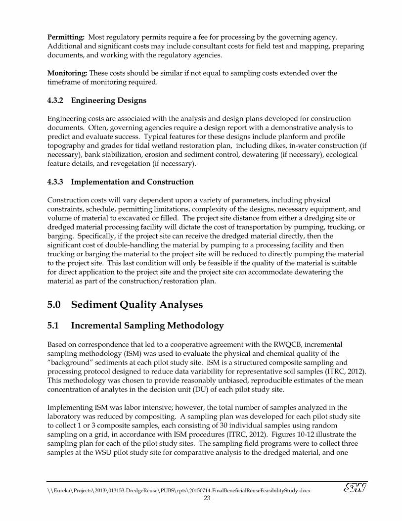
Permitting: Most regulatory permits require a fee for processing by the governing agency. Additional and significant costs may include consultant costs for field test and mapping, preparing documents, and working with the regulatory agencies. Monitoring: These costs should be similar if not equal to sampling costs extended over the timeframe of monitoring required. 4.3.2 Engineering Designs Engineering costs are associated with the analysis and design plans developed for construction documents. Often, governing agencies require a design report with a demonstrative analysis to predict and evaluate success. Typical features for these designs include planform and profile topography and grades for tidal wetland restoration plan, including dikes, in-water construction (if necessary), bank stabilization, erosion and sediment control, dewatering (if necessary), ecological feature details, and revegetation (if necessary). 4.3.3 Implementation and Construction Construction costs will vary dependent upon a variety of parameters, including physical constraints, schedule, permitting limitations, complexity of the designs, necessary equipment, and volume of material to excavated or filled. The project site distance from either a dredging site or dredged material processing facility will dictate the cost of transportation by pumping, trucking, or barging. Specifically, if the project site can receive the dredged material directly, then the significant cost of double-handling the material by pumping to a processing facility and then trucking or barging the material to the project site will be reduced to directly pumping the material to the project site. This last condition will only be feasible if the quality of the material is suitable for direct application to the project site and the project site can accommodate dewatering the material as part of the construction/restoration plan. 5.0 Sediment Quality Analyses 5.1 Incremental Sampling Methodology Based on correspondence that led to a cooperative agreement with the RWQCB, incremental sampling methodology (ISM) was used to evaluate the physical and chemical quality of the “background” sediments at each pilot study site. ISM is a structured composite sampling and processing protocol designed to reduce data variability for representative soil samples (ITRC, 2012). This methodology was chosen to provide reasonably unbiased, reproducible estimates of the mean concentration of analytes in the decision unit (DU) of each pilot study site. Implementing ISM was labor intensive; however, the total number of samples analyzed in the laboratory was reduced by compositing. A sampling plan was developed for each pilot study site to collect 1 or 3 composite samples, each consisting of 30 individual samples using random sampling on a grid, in accordance with ISM procedures (ITRC, 2012). Figures 10-12 illustrate the sampling plan for each of the pilot study sites. The sampling field programs were to collect three samples at the WSU pilot study site for comparative analysis to the dredged material, and one

#
##
#
#
#
###
#
#
# #
#
##
#
#
#
#
#
##
#
#
#
#
#
#
#
_̂_̂
_̂
_̂
_̂
_̂
_̂
_̂
_̂
_̂
_̂
_̂
_̂
_̂
_̂
_̂
_̂
_̂_̂
_̂_̂
_̂
_̂
_̂
_̂
_̂
_̂
_̂
_̂
_̂
!
!
!
!
!
!
!
!
!!
!
!
!
!!
!
!
!
!
!
!
!
!
!
!
!
!
!
!
!
HIGHWAY 101
WHITE SLOUGH
Path: \\
zing\projects\2013\013153-D
redgeReuse\G
IS\Spatial_D
ata\PACK
AGES\FieldSam
plingPlan_W
SU\v101\Fie
ldSam
plingPlan_W
SU.mxd
White Slough Unit Field Sampling PlanHumboldt Bay NWR
SHN 013153Figure 10FieldSamplingPlan_WSUApril 2015
Humboldt Bay HarborRecreation and Conservation District
Humboldt Bay Dredge Sediment Reuse
EXPLANATIONWSU DECISION UNITWSU SAMPLING GRID
! WSU RANDOM SAMPLE 1_̂ WSU RANDOM SAMPLE 2# WSU RANDOM SAMPLE 3
0 500
1" = 500'

!!
!
!!
!
!!
!
!!
!
!
!
!
!!
!
!
!!
!
!!
!
!
!
!
!
!
!
WHITE SLOUGH
HIGHWAY 101
HISTORICALSALMON
CREEK
Path: \\
zing\projects\2013\013153-D
redgeReuse\G
IS\Spatial_D
ata\PACK
AGES\FieldSam
plingPlan_S
CU\v101\
FieldS
amplingPlan_S
CU.mxd
Salmon Creek Unit Field Sampling PlanHumboldt Bay NWR
SHN 013153Figure 11FieldSamplingPlan_SCUApril 2015
Humboldt Bay HarborRecreation and Conservation District
Humboldt Bay Dredge Sediment Reuse
EXPLANATIONSCU DECISION UNITSCU SAMPLING GRID
! SCU RANDOM SAMPLES 1
0 500
1" = 500'

!
!
!
!
!
!
!
!
!
!
!
!
!
!
!
!
!
!
!
!!
!
!
!
!
!
!
!
!
!!
KLOPP LAKE
CITY OF ARCATA WWTFOXIDATION PONDS
BUTCHERS SLOUGH
Path: \\zing\projects\2013\013153-DredgeReuse\GIS\Spatial_Data\PACKAGES\FieldSamplingPlan_AMWS\v101\FieldSamplingPlan_AMWS.mxd
Arcata Marsh and Wildlife SanctuaryLiving Shoreline Field Sampling Plan
Figure 12FieldSamplingPlan_AMWS
Humboldt Bay HarborRecreation and Conservation District
Humboldt Bay Dredge Sediment ReuseApril 2015
SHN 001283
EXPLANATIONAMWS DECISION UNITAMWS SAMPLE GRID
! AMWS RANDOM SAMPLE 1
0 500
1" = 500'

\\Eureka\Projects\2013\013153-DredgeReuse\PUBS\rpts\20150714-FinalBeneficialReuseFeasibilityStudy.docx 24
sample at the SCU and AMWS pilot study sites for initial background conditions. The additional sampling at the WSU pilot study site was made possible by additional funding for laboratory analyses from the Humboldt Bay NWR. 5.2 Field Program The sediment characterization field program consisted of the collection of composite samples, comprised of a minimum of 30 sediment samples at each pilot study DU. Random soil sampling points on a grid were located using a Trimble GPS system. Samples were collected using a soil probe and placed into Ziploc® bags and set on ice. Material was collected from each sample location to a depth up to 1 foot beneath the sediment surface, just below the organic horizon (if present). All material was logged for lithological conditions using the Unified Soils Classification System as described in the ASTM -International (ASTM) D 2488-90. Plants, roots, and peat encountered at each location were removed. Laboratory mass requirements of less than two kilograms were considered prior to sample collection to meet final composite sample weight criteria without sample collection bias. All sampling equipment and hand tools were cleaned prior to field exposure and use onsite. Equipment was cleaned onsite between each sample composite and site location using a distilled water solution containing Liquinox ® cleaner, followed by two distilled water rinses. Access to sample locations for field personnel varied based on site conditions. The SCU pilot study site was relatively dry with stable surface conditions and did not require special equipment. The WSU pilot study site had tidally influenced areas where channels had to be crossed and the ground was saturated, but was relatively stable, so the use of mud-walking boots for field personnel was required. The AMWS is comprised of open mudflats, where a boat was necessary to access the site during a flood tide and submerged samples were collected. Soils were collected at the WSU and SCU on November 11 and 12, 2014. Soils were collected at the AMWS on December 23, 2014. 5.3 Laboratory Analyses 5.3.1 Physical Characteristics SHN’s materials testing laboratory evaluated the physical properties of a single ISM composite sample from each site for texture (percent coarse and fine materials) and plasticity index, using standard ASTM methods. Results are attached in Appendix C and summarized in Table 1.
Table 3 Physical Character of Pilot Study Site Soils
Beneficial Reuse of Dredged Materials Feasibility Study Humboldt Bay Harbor, Recreation, and Conservation District
Pilot Study Site Texture (%) Plasticity Index Gravel Sand Silt Clay
NWR1–White Slough Unit 0.1 13.7 52.5 33.7 34 NWR–Salmon Creek Unit 0 2.6 60.8 36.6 33 AMWS2 Living Shoreline 0 1.9 67.1 31.0 31 1. NWR: Humboldt Bay National Wildlife Refuge 2. AMWS: Arcata Marsh and Wildlife Sanctuary

\\Eureka\Projects\2013\013153-DredgeReuse\PUBS\rpts\20150714-FinalBeneficialReuseFeasibilityStudy.docx 25
In general, the results are consistent. The coarseness of the White Slough sample is likely a result of the samples collected near the wetland/upland transition at the mouth of Chism Creek, where coarser material is likely transported into the project site. In comparison with the 2005 soil samples (in-place sediment samples from the City of Eureka and the District’s marinas and docks), these sites are generally composed of finer material. The relative differences in the material sampled in 2005 appear to be based on their location, because the sampled material graded finer from the mouth of the Eureka Slough Channel, upstream. The percent sand for the 2005 samples ranged from 3-37%; percent silt ranged from 38-60%; and percent clay ranged from 25-45%. Figure 13 displays the texture results at all pilot study sites and an average of the 2005 results.
Figure 13. Sediment Laboratory Analysis Results: Texture 5.3.2 Chemical Constituents The ISM requires that chemical laboratory analyses follow a specific protocol when processing the composite sample to reduce data variability and produce representative results. TestAmerica Laboratories in Sacramento was chosen to process the samples, as they can provide the ISM processing service. Results are summarized in Table 4 and presented in Appendix C.
0
10
20
30
40
50
60
70
% Sand % Silt % Clay
Perc
ent
WSU - 1 SCU - 1 AMWS - 1 Average of 2005 Sampling Results

\\Eureka\Projects\2013\013153-DredgeReuse\PUBS\rpts\20150714-FinalBeneficialReuseFeasibilityStudy.docx 26
Table 4 Laboratory Analyses Results of Pilot Study Sites Sediment Chemical Constituents
Beneficial Reuse of Dredged Materials Feasibility Study Humboldt Bay Harbor, Recreation, and Conservation District
Analyte Method Reporting Limit Units WSU – 1
(Lab ID #1) WSU – 2
(Lab ID #2) WSU – 3
(Lab ID #3) SCU – 1
(Lab ID #4) AMWS – 1 (Lab ID #5)
Total Organic Carbon EPA 9060 4.0 g/kg1 37 37 43 34 12 Total Kjeldahl Nitrogen EPA 351.2 500 mg/kg2 1,600 1,500 1,200 1,100 750 TPH3 as Motor Oil EPA 8015 B 10 mg/kg 210 130 140 190 310 TPH3 as Diesel EPA 8015 B 1.0 mg/kg 31 19 22 30 B 90 Metals Silver EPA 6010 B 0.54 mg/kg ND4 ND ND ND 0.090 J5
Arsenic EPA 6010 B 2.2 mg/kg 9.1 9.5 9.5 8.0 8.3 Barium EPA 6010 B 1.1 mg/kg 50 56 51 45 62 Beryllium EPA 6010 B 0.22 mg/kg 0.54 0.60 0.56 0.54 0.60 Cadmium EPA 6010 B 0.22 mg/kg 0.030 J ND ND 0.047 J 0.16 J Cobalt EPA 6010 B 0.54 mg/kg 7.8 8.6 8.1 8.1 16 Chromium EPA 6010 B 0.54 mg/kg 85 90 93 89 100 Copper EPA 6010 B 1.6 mg/kg 29 29 29 29 40 B6
Nickel EPA 6010 B 1.1 mg/kg 84 88 85 81 120 Lead EPA 6010 B 1.1 mg/kg 22 18 33 14 15 Molybdenum EPA 6010 B 2.2 mg/kg 2.9 3.5 B 3.6 B 4 3.0 Selenium EPA 6010 B 2.2 mg/kg 1.6 J ND ND ND ND Thallium EPA 6010 B 2.2 mg/kg ND ND ND ND 0.97 J Antimony EPA 6010 B 2.2 mg/kg 1.1 J ND 1.2 J 1.3 J ND Vanadium EPA 6010 B 0.54 mg/kg 58 62 62 58 59 Zinc EPA 6010 B 2.2 mg/kg 74 77 77 75 96 Total Mercury EPA 7471 A 0.024 mg/kg 0.095 0.078 0.022 J 0.071 0.13 PCBs7
PCB 1016 EPA 8082A 33 mg/kg ND ND ND ND ND PCB 1221 EPA 8082A 33 mg/kg ND ND ND ND ND PCB 1232 EPA 8082A 33 mg/kg ND ND ND ND ND PCB 1242 EPA 8082A 33 mg/kg ND ND ND ND ND PCB 1248 EPA 8082A 33 mg/kg ND ND ND ND ND PCB 1254 EPA 8082A 33 mg/kg ND ND ND ND ND PCB 1260 EPA 8082A 33 mg/kg ND ND ND ND 4.2 J

\\Eureka\Projects\2013\013153-DredgeReuse\PUBS\rpts\20150714-FinalBeneficialReuseFeasibilityStudy.docx 27
Table 4 Laboratory Analyses Results of Pilot Study Sites Sediment Chemical Constituents
Beneficial Reuse of Dredged Materials Feasibility Study Humboldt Bay Harbor, Recreation, and Conservation District
Analyte Method Reporting Limit Units WSU – 1
(Lab ID #1) WSU – 2
(Lab ID #2) WSU – 3
(Lab ID #3) SCU – 1
(Lab ID #4) AMWS – 1 (Lab ID #5)
Semi-Volatile Organics Naphthalene EPA 8270 C SIM 5.4 µg/kg8 6.2 6.6 8.7 5.2 29 B Acenapthylene EPA 8270 C SIM 5.4 µg/kg ND ND ND ND 3.0 J Acenaphthene EPA 8270 C SIM 5.4 µg/kg 1.7 J 1.9 J 2.3 J 1.3 J 5.8 J Fluorene EPA 8270 C SIM 5.4 µg/kg 3.3 J 4.1 J 4.6 J 2.0 J 33 Phenanthrene EPA 8270 C SIM 5.4 µg/kg 27 28 32 23 91 Anthracene EPA 8270 C SIM 5.4 µg/kg 0.53 J 0.49 J ND ND 7.7 J Fluoranthene EPA 8270 C SIM 5.4 µg/kg 8.2 4.4 J 4.6 J 3.7 J 46 Pyrene EPA 8270 C SIM 5.4 µg/kg 11 7.2 8 4.9 J 59 Benzo(a)anthracene EPA 8270 C SIM 5.4 µg/kg 1.8 J 1.7 J 1.9 J 1.1 J 14 J Chrysene EPA 8270 C SIM 5.4 µg/kg 11 10 11 8.3 35 Benzofluoranthene EPA 8270 C SIM 5.4 µg/kg 10 10 12 7.9 15 J Benzo(a)pyrene EPA 8270 C SIM 5.4 µg/kg 1.7 J 1.2 J 1.3 J 0.51 J 17 J Indeno(1,2,3-cd)pyrene EPA 8270 C SIM 5.4 µg/kg 1.9 J 1.4 J 1.3 J 0.93 J 17 J Dibenz(a,h)anth-racene EPA 8270 C SIM 5.4 µg/kg ND ND ND ND ND Benzo(g,h,i)pery-lene EPA 8270 C SIM 5.4 µg/kg 5.1 4.6 J 4.4 J 2.5 J 28 Organochlorine Pesticides 4,4’-DDD EPA 8081 B 8.5 µg/kg ND ND ND ND 0.42 J p9
4,4’-DDE EPA 8081 B 8.5 µg/kg ND ND ND ND 0.46 J 4,4’-DDT EPA 8081 B 8.5 µg/kg ND ND ND ND ND Aldrin EPA 8081 B 8.5 µg/kg ND ND ND ND ND Alpha-BHC EPA 8081 B 8.5 µg/kg ND ND ND ND ND Alpha-Chlordane EPA 8081 B 8.5 µg/kg ND ND ND ND ND Beta-BHC EPA 8081 B 8.5 µg/kg ND ND ND ND ND Delta-BHC EPA 8081 B 8.5 µg/kg ND ND ND ND ND Dieldrin EPA 8081 B 8.5 µg/kg ND ND ND 0.78 J 0.35 J P10
Endosulfan-I EPA 8081 B 8.5 µg/kg ND ND ND ND ND Endosulfan-II EPA 8081 B 8.5 µg/kg 0.13 J H11 ND ND ND 0.61 J P Endosulfan sulfate EPA 8081 B 8.5 µg/kg ND ND ND ND 1.3 J P Endrin EPA 8081 B 8.5 µg/kg ND ND ND ND ND

\\Eureka\Projects\2013\013153-DredgeReuse\PUBS\rpts\20150714-FinalBeneficialReuseFeasibilityStudy.docx 28
Table 4 Laboratory Analyses Results of Pilot Study Sites Sediment Chemical Constituents
Beneficial Reuse of Dredged Materials Feasibility Study Humboldt Bay Harbor, Recreation, and Conservation District
Analyte Method Reporting Limit Units WSU – 1
(Lab ID #1) WSU – 2
(Lab ID #2) WSU – 3
(Lab ID #3) SCU – 1
(Lab ID #4) AMWS – 1 (Lab ID #5)
Endrin aldehyde EPA 8081 B 8.5 µg/kg ND ND ND ND ND Endrin ketone EPA 8081 B 8.5 µg/kg ND ND ND ND ND Gamma-BHC (Lindane) EPA 8081 B 8.5 µg/kg ND ND ND ND ND Gamma-Chlordane EPA 8081 B 8.5 µg/kg ND ND ND ND ND Heptochlor EPA 8081 B 8.5 µg/kg ND ND ND ND ND Heptochlor epoxide EPA 8081 B 8.5 µg/kg 1.0 J H 1.2 J 1.5 J ND ND Methoxychlor EPA 8081 B 8.5 µg/kg ND ND ND ND ND Toxaphene EPA 8081 B 8.5 µg/kg ND ND ND ND ND Herbicides Pentachlorophenol EPA 8151 A 32 µg/kg ND ND ND ND ND Dioxins and Furans
2,3,7,8-TCDD TEQ WHO 2005/
OEHHA Public Health Goal
N/A pg/g12 0.21 0.35 0.22 0.62 38
2,3,7,8-TCDD EPA 1613 B 1.0 pg/g ND 0.12 J q13 ND ND 0.68 J 2,3,7,8-TCDF EPA 1613 B 1.0 pg/g 0.56 J q 0.64 J 0.67 J 0.56 J 2.2 1,2,3,7,8-PeCDD EPA 1613 B 5.0 pg/g ND ND ND 0.21 J 4.8 J 1,2,3,7,8-PeCDF EPA 1613 B 5.0 pg/g ND ND ND 0.20 J 6.6 2,3,4,7,8-PeCDF EPA 1613 B 5.0 pg/g ND ND ND 0.20 J 12 1,2,3,4,7,8-HxCDD EPA 1613 B 5.0 pg/g ND 0.13 J q 0.16 J 0.23 J q 8.8 1,2,3,6,7,8-HxCDD EPA 1613 B 5.0 pg/g ND 0.16 J q 0.29 J 0.48 J 30 1,2,3,7,8,9-HxCDD EPA 1613 B 5.0 pg/g ND 0.50 J 0.44 J 0.62 J 18 1,2,3,4,7,8-HxCDF EPA 1613 B 5.014 pg/g ND 0.21 J 0.10 J q 0.21 J q 74 G15
1,2,3,6,7,8-HxCDF EPA 1613 B 5.0 pg/g ND 0.063 J ND 0.15 J q 25 1,2,3,7,8,9-HxCDF EPA 1613 B 5.016 pg/g 0.95 J ND ND 0.37 J q ND G 2,3,4,6,7,8-HxCDF EPA 1613 B 5.0 pg/g ND 0.13 J ND 0.23 J 9.1 1,2,3,4,6,7,8-HpCDD EPA 1613 B 5.017 pg/g 4.1 J B 3.5 J 3.8 J 4.4 J B 760 G 1,2,3,4,6,7,8-HpCDF EPA 1613 B 5.018 pg/g 0.62 J q B 0.57 J B 0.59 J B 0.49 J B 280 G 1,2,3,4,7,8,9-HpCDF EPA 1613 B 5.019 pg/g 0.20 J ND ND 0.14 J ND G OCDD EPA 1613 B 1020 pg/g 21 B 16 B 18 B 23 B 4600 E21 G B

\\Eureka\Projects\2013\013153-DredgeReuse\PUBS\rpts\20150714-FinalBeneficialReuseFeasibilityStudy.docx 29
Table 4 Laboratory Analyses Results of Pilot Study Sites Sediment Chemical Constituents
Beneficial Reuse of Dredged Materials Feasibility Study Humboldt Bay Harbor, Recreation, and Conservation District
Analyte Method Reporting Limit Units WSU – 1
(Lab ID #1) WSU – 2
(Lab ID #2) WSU – 3
(Lab ID #3) SCU – 1
(Lab ID #4) AMWS – 1 (Lab ID #5)
OCDF EPA 1613 B 10 pg/g 1.3 J B 1.1 J 1.0 J q 0.85 J B 430 B 1. g/kg: grams per kilogram 2. mg/kg: milligrams per kilogram 3. TPH: total petroleum hydrocarbons 4. ND: nondetectable 5. J: below reporting limit, estimate above or equal to the method detection limit 6. B: compound was found in the blank and sample 7. PCBs: polychlorinated biphenyls 8. µg/kg: micrograms per kilogram 9. p: the relative percent difference (% RPD) between the primary and confirmation column/detector is greater than 40% and the lower value has been reported 10. P: the % RPD between the primary and confirmation column/detector is greater than 40% and the higher value has been reported 11. H: sample was prepped or analyzed beyond the specified holding time 12. pg/g: picograms per gram 13. q: The reported result is the estimated maximum possible concentration of this analyte, quantitated using the theoretical ion ratio. The measured ion ratio does not meet qualitative
identification criteria and indicates a possible interference 14. Reporting limit for AMWS-1 (Lab ID #5) was raised to 5.2 pg/g 15. G: the reported quantitation limit has been raised due to an exhibited elevated noise or matrix interference 16. Reporting limit for AMWS-1 (Lab ID #5) was raised to 6.0 pg/g 17. Reporting limit for AMWS-1 (Lab ID #5) was raised to 44 pg/g 18. Reporting limit for AMWS-1 (Lab ID #5) was raised to 15 pg/g 19. Reporting limit for AMWS-1 (Lab ID #5) was raised to 27 pg/g 20. Reporting limit for AMWS-1 (Lab ID #5) was raised to 51 pg/g 21. E: result exceeded calibration range

\\Eureka\Projects\2013\013153-DredgeReuse\PUBS\rpts\20150714-FinalBeneficialReuseFeasibilityStudy.docx 30
5.4 Preliminary Comparison of Laboratory Results This inspection presents a comparison between the laboratory results from the pilot study sites to the 2005 dredge sediment sampling data. These results are considered preliminary because the data for comparison is from a previous dredging event in 2005, not all of the laboratory analyses were the same, and the field sample collection methods were different. Charts of the comparative results that could be illustrated are included. 5.4.1 Texture Figure 13 illustrates the range of texture between the three pilot study sites in comparison with an average texture from the 2005 dredge sediment results. Based on the soil texture comparison, the dredge sediment, as represented by the 2005 data, would be an excellent supplement to the pilot study sites to restore tidal wetlands. 5.4.2 Total Organic Carbon Figure 14 illustrates the range of total organic carbon (TOC) between the three pilot study sites in comparison with the average TOC from the 2005 dredge sediment results. The TOC at WSU and SCU are consistent, ranging from 34 to 43 grams per kilogram (g/kg). The 2005 dredge sediment average TOC was more similar to the mudflats sampled at AMWS, 19 and 12 g/kg, respectively. Based on the TOC comparison, the dredge sediment, as represented by the 2005 data, would be an excellent supplement to the AMWS pilot study site to construct a living shoreline. The soil at the WSU and SCU pilot study sites were richer in TOC; however, any fill source amendment for tidal restoration at these sites, other than compost, would likely have a lower TOC content.
Figure 14. Sediment Laboratory Analysis Results: Total Organic Carbon

\\Eureka\Projects\2013\013153-DredgeReuse\PUBS\rpts\20150714-FinalBeneficialReuseFeasibilityStudy.docx 31
5.4.3 Metals Figure 15 shows the range of results for arsenic, chromium, copper, nickel, lead, and zinc between the three pilot study sites in comparison with the average of soil concentrations of these metals from the 2005 dredge sediment results. Although not represented in Figure 15, the maximum soil concentrations of these metals from all of the 2005 dredge sediment samples were below the background metals sampled at the pilot study sites, with the exception of zinc, which was greater at the Coast Seafoods Dock with a concentration of 83.4 milligrams per kilogram (mg/kg).
Figure 15. Sediment Laboratory Analysis Results: Metals Figure 16 shows the range of total mercury between the three pilot study sites in comparison with the average of the soil concentration from the 2005 dredge sediment results. The “WSU-2” sample was below the reporting limit of 0.024 mg/kg, dry weight and above the method detection limit (“J” flag on the laboratory results), and estimated to be 0.022 mg/kg, dry weight. 2005 dredge sediment soil concentrations of total mercury ranged from “not detected” (with unknown reporting and method detection limits) to a maximum dry weight soil concentration at the Fisherman’s Dock Terminal of 0.18 mg/kg. Note that the average total mercury concentration from the 2005 data may be an over-estimate, because it only included detected concentrations.

\\Eureka\Projects\2013\013153-DredgeReuse\PUBS\rpts\20150714-FinalBeneficialReuseFeasibilityStudy.docx 32
Figure 16. Sediment Laboratory Analysis Results: Total Mercury 5.4.4 Polychlorinated Biphenyls All polychlorinated biphenyls (PCBs) tested were not detected in the soils at the pilot study sites, with the exception of a detection of PCB 1260 below the reporting limit of 33 mg/kg at a J-flag concentration estimate of 4.2 mg/kg. PCB (Arcolor) 1254 and 1260 were detected in 2005 at the Coast Seafoods Dock and Fisherman’s Dock Terminal, with total PCB soil concentrations of 0.20 and 0.034 mg/kg, respectively. The 2005 dredge sediment results reporting and method detection limits for PCBs are unknown. 5.4.5 Semi-Volatile Organics Soil concentrations of semi-volatile organics (SVOCs) within the pilot study sites were minimal in comparison with the 2005 dredge sediment sample results. The 2005 dredge sediment concentrations varied significantly between docks. For example, soil concentrations of acenaphthene ranged at Dock B from 5.1 micrograms per kilogram (µg/kg) (below concentrations detected at AMWS) to 357 µg/kg at the Fisherman’s Dock Terminal. 5.4.6 Organochloride Pesticides All detections of organochloride pesticide soil concentrations at the pilot study sites were below the reporting limits and estimated above the method detection limits (summarized in Table 4). The 2005 dredge sediment sample results do not include organochloride pesticides.

\\Eureka\Projects\2013\013153-DredgeReuse\PUBS\rpts\20150714-FinalBeneficialReuseFeasibilityStudy.docx 33
5.4.7 Herbicides The single herbicide tested at the pilot study sites was pentachlorophenol (PCP), which was not detected at any of the sites. The 2005 sediment sampling results of PCP soil concentrations were detected below the reporting limits with J flag estimates at the Small Boat Basin, “I” Street Dock, and the Woodley Island Marina, ranging from 1.8 to 8.3 µg/kg. The 2005 dredge sediment results reporting limits for PCP varied by site and are summarized in Table 2. 5.4.8 Dioxins and Furans The methods of calculating the 2,3,7,8-TCDD toxicity equivalents (TEQs) for the 2005 sediment samples used the WHO 1997 TEFs; however, the results were consistent with recalculated results using the WHO 2005 TEFs and were, therefore, comparable to the pilot study data results. As shown in Table 4, the 2,3,7,8-TCDD TEQs ranged from 0.21 to 0.35 pg/g from the three samples collected at WSU, and were 0.62 pg/g at SCU and 38 pg/g at AMWS. The 2005 sediment sampling results of the 2,3,7,8-TCDD TEQs (Table 2) ranged from the lowest composite levels of 0.78 to 1.1 pg/g at the Woodley Island Marina to the most elevated composite levels of 4.9 to 6.0 pg/g at Coast Seafoods Dock. 6.0 Preferred Pilot Projects Each project considered in this study warranted the position of a “preferred pilot project” for different reasons. The Humboldt Bay NWR White Slough Unit project is the obvious choice to implement first, because it is furthest along in the design and permitting processes and the risk of the dike failure poses and immediate need for action. Due to the chemical quality of the soil, the Arcata Marsh and Wildlife Sanctuary living shoreline project could likely benefit the greatest by capping any contaminated soils that have been transported to the mouth of Butchers Slough; conceptual designs for this project have recently been funded by the State Coastal Conservancy. Finally, both the Humboldt Bay NWR Salmon Creek and Hookton Slough Units are very low in elevation relative to the sea level; a result of subsidence, downward vertical land motion, and relative sea level rise. These two projects offer incredible large-scale opportunities to restore tidal function and salt marsh habitat to diked former tidelands. Conceptual designs were developed for the Humboldt Bay NWR Salmon Creek and Hookton Slough Units as part of this feasibility study and are attached in Appendix D. All references to conceptual design channel geometries are based on Design Guidelines for Tidal Wetland Restoration in San Francisco Bay (PWA and Faber, 2004). Applicability of these methods in Humboldt Bay was confirmed in Tidal Wetland Geometric Relations in Humboldt Bay: Mad River Slough Pilot Project (Anderson and Patenaude, 2009). 6.1 Humboldt Bay National Wildlife Refuge Salmon Creek Unit
Conceptual Design Summary 6.1.1 Site Conditions The Salmon Creek Unit project pilot study site is within a portion of the historical Salmon Creek marsh plain. Remnant channels onsite are virtually nonexistent; however, a few depressions are

\\Eureka\Projects\2013\013153-DredgeReuse\PUBS\rpts\20150714-FinalBeneficialReuseFeasibilityStudy.docx 34
located in the landscape and appear to result from stormwater ponding and may provide a good footprint for tidal or brackish ponds, depending on the water quality. At least two points along the northern site boundary provide stormwater drainage into the project site. The surface elevation of the proposed marsh plain has subsided significantly, with a mean elevation of approximately 3 feet, below MTL. It would be necessary to bring the site up to at least the MTL elevation to ensure low marsh vegetation colonization, with a preference toward an elevation of mean high water (MHW; 5.81 feet at the North Spit), to support a greater diversity of salt marsh flora and interior ponds. 6.1.2 Conceptual Design Features Construct an Ecotone Dike to Protect Highway 101 and NWR Property to the East: A linear stormwater channel is located along the northern border of the project site, south of Highway 101. This channel is well vegetated with riparian trees and appears to drain into the project site at two locations. Based on the 2009-2011 California Coastal Conservancy Lidar Project data (NOAA, 2012), this stretch of highway dips to below 9.75 feet in elevation. This indicates that an extension of the shoreline, from opening up the site to full tidal exchange, would put the highway at risk of “high vulnerability,” as defined in the Humboldt Bay Shoreline Inventory, Mapping and Sea Level Rise Vulnerability Assessment (Laird, 2013). Although this condition could be controlled by a muted tidal prism, regulated by a tide gate, this project presents the option for full tidal exchange with the bay. If the road was not raised, then one option would be to construct an ecotone dike that grades at a slope of 1:10 horizontal to vertical (H:V) from the existing ground surface elevation (relatively 2.75 feet) to the design elevation of 9.75 feet, then back down to the existing, but degraded berm on the south side of the stormwater channel, which varies in grade, but has an estimated average elevation of 4.75 feet. The degraded berm would need to be flattened longitudinally and then sloped upward to the maximum design ecotone dike elevation or 9.75 feet, requiring approximately 50 feet in width. The approximate width of the ecotone dike from its maximum height of 9.75 feet to the existing surface elevation would require another 70 feet, for a total width of approximately 120 feet. Storm drainage structures would need to be constructed beneath the ecotone dike to allow stormwater to drain on to the project site and gated so that tidewater remains onsite. It can be assumed that a similar ecotone dike can be constructed along the eastern boundary of the site to inhibit salt water from flooding fields that are used for cattle grazing. The required material and volumes to construct these dikes has not yet been estimated. Excavate Slough Channels: A single channel network is proposed, with the main channel located in an existing drainage footprint created by stormwater draining north to south through the tide gate located between the project site and the tidally controlled historical Salmon Creek channel. The project surface elevation is relatively level, which will probably require channel excavation of both main (first-order) and secondary (second-order) channels, depending on design depths. Third-order channels will likely evolve naturally from the hydraulic power of tidal exchange. All culverts internal to the project site are proposed for removal. The volume of excavation to construct these channels has not yet been estimated. Remove Trees and Stockpile for Wildlife Habitat: There is a small thicket of trees, composed of eucalyptus, pine, and cypress located along the western boundary of the project site. These trees are located on a surface elevation, relatively close to MHW, which should convert to salt marsh plain fairly rapidly, without raising surface elevation.

\\Eureka\Projects\2013\013153-DredgeReuse\PUBS\rpts\20150714-FinalBeneficialReuseFeasibilityStudy.docx 35
Remove and Block the Existing Tide Gates that Drain to the Historical Salmon Creek Channel: Two tide gates are located along the southern project boundary, and drain the fields into the historical Salmon Creek channel. In order to promote full tidal exchange through the design slough mouth, located on White Slough, these tide gates will be removed and blocked. Fill Ditches and Remove any Internal Culverts: Stormwater ditches are proposed to be filled and flow redirected into design slough channels. Internal culverts will be removed to encourage natural scouring. The volume of material needed to fill the existing ditches has not yet been estimated. Increase the Marsh Plain Elevation by Filling with Fine Sediment: The existing ground surface is below MTL, indicating that with full tidal exchange, the existing meadow will be converted to mudflat. To promote native salt marsh vegetation colonization, the surface elevation is proposed to grade from MTL elevation (3.37 feet at the North Spit) to MHW elevation (5.81 feet at the North Spit). To raise the marsh plain surface to the minimum design elevation (MTL) would require approximately 115,000 cubic yards of fill. Reuse of dredged sediment would provide substrate that is fairly equal in texture to the existing site soils. Breach Slough Mouth: To accommodate the proposed slough network and design tidal prism, the slough mouth is proposed to be breached into White Slough, to design channel geometries. For the design marsh plain area of 80 acres, it is expected that the estimated mouth width will need to be 70 feet. The volume of material to be removed during these breaches has not yet been estimated. 6.2 Humboldt Bay National Wildlife Refuge Hookton Slough Unit
Conceptual Design Summary 6.2.1 Site Conditions The Hookton Slough Unit project pilot study site is unique in its landscape. Freshwater inputs from minor, unnamed tributaries drain from west to east, through drainage structures under Hookton Road that can provide brackish marsh and channel zones at the upstream end of the slough channels and possibly extend downstream into Hookton Slough. There is also the potential to construct brackish ponds within the project footprint, though none is presented in the conceptual design. 6.2.2 Conceptual Design Features Construct an Ecotone Dike to Protect Hookton Road: A portion of Hookton Road, adjacent to the project site ranges in elevation from approximately 4.75 to 5.75 feet, below MHHW elevation, indicating that the road would be flooded regularly by ebbing tides, if the project site was open to full tidal inundation. Although this condition could be controlled by a muted tidal prism, regulated by a tide gate, this project presents the option for full tidal exchange with the bay. If the road was not raised, then one option would be to construct an ecotone dike that grades at a slope of 1:10 H:V from the existing ground surface elevation (relatively 2.75 feet) up to the design elevation of 9.75 feet and then back down to the road elevation. In its given condition, the road would need an approximately 40 to 50 feet offset to grade up to the design ecotone dike elevation. The approximate width of the ecotone dike from its maximum height of 9.75 feet to the existing surface elevation is 70 feet, requiring at total width of 110 to 120 feet. All storm drainage structures would

\\Eureka\Projects\2013\013153-DredgeReuse\PUBS\rpts\20150714-FinalBeneficialReuseFeasibilityStudy.docx 36
need to be reconstructed beneath the ecotone dike to allow surface water to drain to the project site, and gated so that tidewater remains onsite. The required material and volumes to construct these dikes has not yet been estimated. Excavate Slough Channels: Two channel networks, simply designated North and South Sloughs, with separate outlets, were designed based on historical slough systems that drained the project site, prior to the bayfront dike construction. To conceptualize the completed channel restoration, the illustration of the slough channel networks in Appendix D illustrates main (first-order), secondary (second-order), and tertiary (third-order) channels. It is likely that in general, only the first-order channels will need to be excavated to design channel geometries; the second- and third-order channels will evolve naturally from the hydraulic power of tidal exchange, because they were designed within the remaining footprints of historic tidal channels. The volume of excavation to construct these channels has not yet been estimated. Fill Ditches: It is imperative that the ditches that were historically excavated for drainage be filled to concentrate tidal and freshwater hydraulic energy into the slough channels. This hydrologic contribution will help maintain the design channel geometries and provide the opportunity for a greater variety of fisheries species to use the project site by maintaining a channel network that feeds deeper main channels, allowing for topographic and water quality gradients. The volume of material needed to fill the existing ditches has not yet been estimated. Increase the Marsh Plain Elevation by Filling with Fine Sediment: The existing ground surface is below MTL, indicating that with full tidal exchange, the existing wetlands and uplands will be converted to mudflat. To promote native salt marsh vegetation colonization, the surface elevation is proposed to grade from MTL elevation (3.37 feet at the North Spit) to MHW elevation (5.81 feet at the North Spit). Raising the marsh plain surface to the minimum design elevation of MTL would require approximately 125,000 cubic yards of fill. Reuse of dredged sediment would provide substrate that is fairly equal in texture to the existing site soils. Breach Slough Mouths: To accommodate the proposed slough network and design tidal prism, the slough mouths are proposed to be breached to design channel dimensions. The volume of material to be removed during these breaches has not yet been estimated. Remove Bayfront Dikes for Full Tidal Exchange/Grade Marsh Plain Toward Slough Channels: To allow full tidal exchange for sediment to accrete and build up the marsh plains as sea level continues to rise, approximately 3,200 feet of bayfront dike is proposed for removal. The volume of material produced by removing these dikes has not yet been estimated. 7.0 References Anderson, J.K. (2015). Humboldt Bay: Sea Level Rise, Hydrodynamic Modeling and Vulnerability
Mapping. Prepared for the State Coastal Conservancy and Coastal Ecosystems Institute of Northern California. McKinleyville, CA: Northern Hydrology & Engineering.
Anderson, J.K. and J.R. Patenaude. (2009). Tidal Wetland Geometric Relations in Humboldt Bay: Mad River Slough Pilot Project. Prepared for the United States Fish and Wildlife Service. McKinleyville, CA: Northern Hydrology & Engineering.
Barnhart, R.A., M.J. Boyd, and J.E. Pequegnat. (1992). The Ecology of Humboldt Bay, California: An Estuarine Profile. U.S. Fish and Wildlife Service Biological Report 1.

\\Eureka\Projects\2013\013153-DredgeReuse\PUBS\rpts\20150714-FinalBeneficialReuseFeasibilityStudy.docx 37
Costa, S. L. (1982). "The Physical Oceanography of Humboldt Bay“ in C. Toole and C. Diebel (ed.), Proceedings of the Humboldt Bay Symposium. Humboldt State University Center for Community Development, Arcata, CA.
Cahoon, D. R., P. F. Hensel, T. Spencer, D. J. Reed, K. L. McKee, and N. Saintilan. (2006). “Coastal Wetland Vulnerability to Relative Sea-Level Rise: Wetland Elevation Trends and Process Controls.” in J. T. A. Verheven, B. Beltman, R. Bobbink, and D. F. Whigham, editors. Wetlands and Natural Resource Management: Ecological Studies 190 xxii. 347 pp.. New York, NY:Springer.
Callaway J.C., E.L. Borgnis, R.E. Turner, and C.S. Milan. (2012). “Carbon Sequestration and Sediment Accretion in San Francisco Bay Tidal Wetlands,” in Estuaries and Coasts 35: 1163–1181. NR:Springer.
Chmura, G. L., S. C. Anisfeld, D. R. Cahoon, and J. C. Lynch. (2003). “Global Carbon Sequestration in Tidal, Saline Wetland Soils,” in Global Biogeochem Cycles, 17(4), 1111, doi:10.1029/ 2002GB001917. Washington, D.C.:AGU.
Cowardin, L. M., V. Carter, F. C. Golet, and E.T. LaRoe. (1979). Classification of Wetlands and Deepwater Habitats of the United States. FWS/OBS-79/31. Washington, D.C.:USFWS.
Interstate Technology and Regulatory Council. (2012). “Incremental Sampling Methodology.” ISM-1. Washington, D.C.: ITRC, Incremental Sampling Methodology Team. Accessed at: www.itrcweb.org.
Laird, Aldaron. (2007). Historical Atlas of Humboldt Bay and Eel River Delta. Prepared for Humboldt Bay Harbor, Recreation and Conservation District and the California Department of Fish and Game. Arcata, CA: Trinity Associates.
---. (2013). Humboldt Bay Shoreline Inventory, Mapping and Sea Level Rise Vulnerability Assessment. Prepared for the State Coastal Conservancy. Arcata, CA: Trinity Associates.
McLaughlin, J. and F. Harradine. (1965). Soils of Western Humboldt County, California. NR:University of Davis and County of Humboldt.
Moffat and Nichols. (2013). Coastal Regional Sediment Management Plan: Eureka Littoral Cell, California. Prepared for: California Coastal Sediment Management Workgroup (Under Contract to U.S. Army Corps of Engineers, Los Angeles District). NR:Moffat and Nichols.
National Oceanic and Atmospheric Administration (2012). 2009-2011 California Coastal Conservancy Lidar Project. A joint effort by the NOAA Office for Coastal Management (NOAA); the California State Coastal Conservancy (SCC) Ocean Protection Council (OPC); Scripps Institution of Oceanography; and the Joint Airborne Lidar Bathymetry Technical Center of Expertise (JALBTCX).
Pacific Affiliates. (2005). City of Eureka and Humboldt Bay Harbor, Recreation and Conservation District: Sediment Sampling Analysis. Eureka, CA.
Philip Williams & Associates, Ltd and P. M. Faber. (2004). Design Guidelines for Tidal Wetland Restoration in San Francisco Bay. 83pp. Oakland, CA:The Bay Institute and California State Coastal Conservancy.
Watson, E.B. (1925). Soils Survey of the Eureka Area, California. Washington D.C.: U.S. Department of Agriculture, Bureau of Soils, in Cooperation with the University of California Agricultural Experimental Station.
U.S. Department of Agriculture National Resources Conservation Service. (Accessed July 15, 2014). Web Soil Survey: http://websoilsurvey.sc.egov.usda.gov/App/WebSoilSurvey.aspx.

A Adv
isor
y C
omm
ittee
and
Com
men
ts

\\Eureka\Projects\2013\013153-DredgeReuse\PUBS\rpts\20150424-Draft-FinalBeneficialReuseFeasibilityStudy-APPENDICES\APPENDIX_A\Advisory Committee.docx
Advisory Committee Affiliation Bruce Young City of Eureka Miles Slattery City of Eureka Jeff Raimey City of Eureka Rob Holmlund City of Eureka Riley Topolewski City of Eureka Lisa Shikany City of Eureka Doby Class City of Arcata Mark Andre City of Arcata Larry Oteker City of Arcata Mark Wheetley City of Arcata Kevin Hamblin Humboldt County Rob Wall Humboldt County John P. Miller Humboldt County Hank Seemann Humboldt County Marcella Clem Humboldt County Association of Governments Bob Merrill California Coastal Commission Melissa Kraemer California Coastal Commission Diane Henrioulle North Coast Regional Water Quality Control Board Craig Hunt North Coast Regional Water Quality Control Board Dave Parson North Coast Regional Water Quality Control Board Gil Falcone North Coast Regional Water Quality Control Board Gordon Leppig California Department of Fish & Wildlife Vicki Frey California Department of Fish & Wildlife Rebecca Garwood California Department of Fish & Wildlife Michael Van Hattem California Department of Fish & Wildlife Rex Jackman Caltrans Jaime Hostler Caltrans Scott Lee Caltrans Steven Kullmann Wiyot Tribe Debra O'Leary US Army Corps of Engineers Mark D'Avignon US Army Corps of Engineers Carol Heidsiek US Army Corps of Engineers Eric Nelson US Fish & Wildlife Services Kenneth Griggs US Fish & Wildlife Services Conor Shea US Fish & Wildlife Services Paula Golightly US Fish & Wildlife Service Andrea Pickart US Fish & Wildlife Service Dave Fuller Bureau Land Management Jonathan Shultz National Resources Conservation Service Becky Price-Hall Humboldt Bay Initiative Jill Demers Coastal Ecosystems Institute of Northern California Joe Tyburczy California Sea Grant Extension Jennifer Kalt Humboldt Baykeeper Dan Ehresman Northcoast Environmental Center Chet Ogan Redwood Region Audubon Society Carol Vander Meer Friends of the Dunes Mark Colwell Humboldt State University

From: "Joe Tyburczy" <[email protected]> To: "Aldaron Laird" <[email protected]> Cc: "Rose Patenaude" <[email protected]> Date: 01/21/14 17:27 Subject: Re: Humboldt Bay Sediment Reuse Advisory Committee Invitation Hi Aldaron, Below are my thoughts on the proposed work. Thanks again for including me on the advisory committee for this exciting project. Cheers, Joe Input regarding the three potential feasibility study sites proposed: 1) Restoring salt marsh on compacted former tidelands behind a dike on the verge of breaching at the Humboldt Bay Wildlife Refuge in South Bay. One key advantage to this project is that it would serve as a useful pilot/proof of concept for reuse of sediment to allow continued use of low-lying agricultural lands until they are eventually inundated by sea level rise. A very interesting demonstration project would be to fill one area with dredge sediment and leave a similar, control area unfilled and monitor their ecological communities and function. This would provide very useful information about the possible fate of similar, privately held lands - empirical data on whether filling would allow them to function as marsh, instead of mud flat, when they are eventually inundated. As was mentioned during the Advisory Committee's first meeting, this project use might be easier to permit with the CCC since it would involve restoring previously drained salt marsh habitat - instead of creating salt marsh habitat where mud flats or eelgrass previously existed. 2) Creating living shoreline, salt marsh fetch attenuation plains, protection for Arcata's wastewater treatment ponds. This project would protect an essential facility (wastewater) for Arcata in addition to their huge investment in, and ecological success with the Arcata Marsh and Wildlife Sanctuary. Further, this project would serve as an invaluable proof-of-concept for the use of horizontal levees to attenuate wave energy in Humboldt Bay. If the project could be used to not only decrease the slope angle, but also increase the height of the levees to some extent, it would serve as an even more versatile demonstration project. 3) Creating ingress and egress access trails and elevating salt marsh at the Wiyot tribe's Tuluwat site north of Samoa Bridge. Though this project would serve a valuable service and protect a cultural heritage site and associated activities, I think these benefits will have less positive impact on the region than either of the other two projects. I believe that priority should go to one of the other two possible uses: protecting the substantial investment in the Arcata Marsh and Wildlife Sanctuary and associated wastewater treatment facility (while demonstrating the use of horizontal levees in Humboldt Bay) or piloting a means to allow extensive diked former tidelands to continue agricultural production - and then revert to tidal marsh when inundated by sea level rise. A few final thoughts:

One concern mentioned at the meeting was displacing existing mud flat habitat - which would likely occur to some extent with any of these projects. I would argue that this should not be a significant concern given that this habitat type is common enough within the bay that none of these projects will significantly alter its overall abundance or even local distribution. Moreover, mud flats, though an important habitat type, do not serve as nursery habitat like eelgrass beds. Newly deposited sediments may be more susceptible to colonization by invasives (Spartina densiflora and Zostera japonica) - so efforts to monitor and prevent this (in addition to encouraging establishment of native species) should be considered.

January 21, 2014 Mr. Aldaron Laird, Project Planner Trinity Associates 980 7th Street, Suite K Arcata, CA 95521 [email protected] Re: Feasibility Study for Beneficial Reuse of Dredged Material for Tidal Marsh
Restoration and Sea Level Rise Adaptation in Humboldt Bay Dear Mr. Laird, On behalf of the board, staff and supporting members of Humboldt Baykeeper, these comments are submitted for your consideration in the Feasibility Study for Beneficial Reuse of Dredged Material for Tidal Marsh Restoration and Sea Level Rise Adaptation in Humboldt Bay. Humboldt Baykeeper was launched in October 2004 to safeguard our coastal resources for the health, enjoyment, and economic strength of the Humboldt Bay community through education, scientific research, and enforcement of laws to fight pollution. We greatly appreciated the thorough presentations and subsequent discussion at the Sediment Technical Advisory Committee’s first meeting, and look forward to future discussions about the Feasibility Study. Humboldt Baykeeper's primary concern with beneficial reuse of dredged material for tidal marsh restoration and sea level rise adaptation in Humboldt Bay is with the reuse of contaminated dredged material and potential introduction of contaminants in restored areas intended to support wildlife habitat. Based on prior sediment sampling results from the City of Eureka and Woodley Island marinas, as well as commercial docks on Humboldt Bay that require periodic dredging, and former industrial sites known to be sources of contamination, the contaminants of particular concern include dioxins and furans, PCBs, heavy metals, petroleum hydrocarbons, volatile organic compounds, and radionuclides.

We strongly recommend that the feasibility study include acquisition and assessment of existing sediment sampling data for radionuclides and other contaminants from PG&E. Radionuclides are of concern in Humboldt Bay sediments due to effluent discharges during and after the active operation of the Humboldt Bay Power Plant’s nuclear reactor. Numerous effluent discharges containing radionuclides were documented over the life of the plant, which is currently being decommissioned. The enclosed document1 is one of several that we have come across in our research that suggests that radioactive contamination from the Humboldt Bay Power Plant has traveled off-‐site. Note that mussels with elevated levels of radionuclides were collected from a sample site called Humboldt Bay Beach Jetty (see p. 321). Of particular concern are the levels of 238Pu detected at the higher end of levels found in this study of numerous sites along the Pacific and Atlantic Coasts of the U.S. We also recommend that detection limits for dioxins and furans be set at 1 ppt for 2,3,7,8-‐TCDD. Dioxins and furans are extremely harmful to human health and the environment at exceptionally low doses, and too often we see sampling plans with detection limits of 5 ppt. In general, sediment quality guidelines and objectives most protective of marine organisms should be used. If receiving sites are found to have contaminated soils, they may not be appropriate for habitat restoration that will promote increased use by wildlife. We recommend that the interested public be given the opportunity to review the sampling plans, sampling results, and restoration plans. Such review by local experts will undoubtedly improve the proposed projects. Thank you for the opportunity to comment on this matter. Sincerely, _________/s/_____________ Jennifer Kalt, Policy Director Humboldt Baykeeper 1385 Eighth Street, Suite 228 Arcata, CA 95521 (707) 499-3678 [email protected]
1 Radionuclide Concentrations in Bivalves Collected Along the Coastal United States. NATHALIE J. VALETTE-‐SILVER and GUNNAR G. LAUENSTEIN. Marine Pollution Bulletin, Vol. 30, No. 5, pp. 320-‐331, 1995.

From: Mark A. Colwell [mailto:[email protected]] Sent: Friday, January 17, 2014 7:14 AM To: Aldaron Laird Subject: Re: Humboldt Bay Sediment Reuse Advisory Committee Invitation Good morning Aldaron, A brief summary of my observations/opinions: 1) Best site is the White Slough location on HBNWR. I base this on the opportunity to use fill to create salt marsh while not compromising the amount of tidal flat. The Arcata site takes away tidal flat. No real ecological benefit to choosing the Tuluwaat site. 2) I reiterate that tidal flat is valuable habitat for many species. Moreover, projections are a greater loss of this habitat (because it lies "downslope" from salt marsh and will be affected sooner by rising sea levels). Thanks for including me in the project discussion. Mark

January 19, 2014 Re: Humboldt Bay sediment reuse Aldaron, Thank you for inviting me to attend the meeting. I agree with all the locations mentioned for spreading the sediment. I think that for use locations to be chosen, they have to be economical. As you pointed out in your excellent study of dike vulnerability around Humboldt Bay, many areas are critical. I would like to see areas targeted where infrastructure is most affected as spoils disposal sites. The next step is to prioritize these areas. I see the businesses and Murray Field along Jacobs Avenue as vital areas to protect. The railroad between Arcata and Eureka serves as the buffer against rising seas. There are several areas where the fetch of the waves pounds against and weakens this levee. If these areas were filled to the height that salt marsh can take hold along the bay side of the railroad, that salt marsh would dissipate the power of the waves. Immediately north of California Redwood (Brainard) and immediately north along 101 offshore off Bracut where Rocky Gulch enters into the bay are two such places where salt marsh establishment would protect the railroad levee. At Bracut the salt marsh might need to be engineered as a linear one offset into the bay from the outflow of Rocky Gulch to allow the creek to freely flow. For an example of that type of salt marsh protection one only needs to look at McDaniel Slough or the mouth of Jacoby Creek. As already pointed out, buffering and enhancing the levees at Arcata Sewage Treatment Plant is important. Thank you Chet Ogan

B Pote
ntia
l Pilo
t Pro
ject
s

\\Eureka\Projects\2013\013153-DredgeReuse\PUBS\rpts\20150424-Draft-FinalBeneficialReuseFeasibilityStudy-APPENDICES\APPENDIX_B\Potential Pilot Projects Table.docx
Site ID Bay Location Potential Pilot Study Site 1 Arcata Bay Gannon Slough 2 Arcata Bay North Bayside 3 Arcata Bay South Bayside 4 Arcata Bay South Arcata 5 Arcata Bay Jacoby Creek to Bracut 6 Arcata Bay AMWS Living Shoreline at Klopp Lake 7 Arcata Bay AMWS Living Shoreline at Oxidation Ponds 8 Arcata Bay McDaniel Slough East 9 Arcata Bay McDaniel Slough Northwest
10 Arcata Bay McDaniel Slough West 11 Arcata Bay South Highway 255 12 Arcata Bay South of McDaniel Slough 13 Arcata Bay McDowell's 14 Arcata Bay Mad River Slough West 15 Arcata Bay Sierra Pacific Industries 16 Arcata Bay Bracut to California Redwood Company 17 Arcata Bay North Eureka Slough 18 Arcata Bay South Eureka Slough/Freshwater Slough 19 Arcata Bay Christie's Ranch 20 Arcata Bay California Redwood Company to Eureka Slough 21 Arcata Bay South of Eureka Slough Mouth 22 Arcata Bay North Indian Island 23 Entrance Bay South Indian Island 24 Entrance Bay PALCO Marsh 25 Entrance Bay Elk River Slough 26 Entrance Bay Elk River Slough at City of Eureka's WWTF 27 Entrance Bay Elk River to King Salmon 28 Entrance Bay Elk River Slough Spit 29 South Bay North King Salmon 30 South Bay South King Salmon 31 South Bay Fields Landing 32 South Bay Humboldt Bay NWR White Slough Unit 33 South Bay North Humboldt Bay NWR Salmon Creek Unit 34 South Bay South Humboldt Bay NWR Salmon Creek Unit 35 South Bay Humboldt Bay NWR Hookton Slough Unit 36 South Bay South Spit 37 South Bay Southwest Corner of South Bay

18
17
12
36
1
11
25
14
34
2
35
4
23
33
10
3
1315
19
27
28
37
20
5
2422
8 32
3130
26
16
29
9
76
21
Source: Esri, DigitalGlobe, GeoEye, i-cubed, Earthstar Geographics, CNES/Airbus DS, USDA, USGS, AEX, Getmapping, Aerogrid, IGN, IGP, swisstopo, and theGIS User Community
Path: \\
zing\projects\2013\
013153-D
redgeReuse\G
IS\Spatial_D
ata\PACK
AGES\P
otentialPilotStudySites\V102\PotentialPilotStudySites.m
xd
Potential Pilot Study SitesHumboldt Bay
SHN 013153Figure B-1PotentialPilotStudySitesApril 2015
Humboldt Bay HarborRecreationi and Conservation District
Humboldt Bay Dredge Sediment Reuse0 6,000
1" = 6000'SOURCES: 2009-2011 CALIFORNIA COASTAL CONSERVANCY LIDAR PROJECT
NORTH (ARCATA)BAYCITY OF
ARCATA
CITY OFEUREKA
ENTRANCEBAY
SOUTHBAY
SAMOA DREDGED SEDIMENTPROCESSING FACILITY
FIELDS LANDINGDREDGED SEDIMENT PROCESSING FACILITYSAMOA "PULP MILL"
DREDGED SEDIMENTPROCESSING FACILITY

C Labo
rato
ry A
naly
ses
Included in PDF only

D Pref
erre
d Pi
lot P
roje
cts
Con
cept
ual D
esig
ns

DDDD
DDDD
CONTROL SURFACE WATER DRAINAGETO PROJECT SITE THROUGH FLOOD GATES
FILL DITCHES TO CONCENTRATEFLOW INTO SLOUGH CHANNELS
CONSTRUCT INTERNAL ECOTONETO AN ELEVATION OF 9.75 FT (NAVD88)OR HIGHER (APPROXIMATELY 120 FT WIDE)
REMOVE AND BLOCK EXISTING TIDEGATES CONNECTED TO THE HISTORICAL SALMON CREEK CHANNEL
EXCAVATE MAIN SLOUGHCHANNELS TO DESIGNMORPHOLOGY
BREACH DIKE TO CONNECT THE MOUTH OF MAIN SLOUGH CHANNELWITH WHITE SLOUGH
REMOVE EXISTING TREESGROWING AT TARGET SALTMARSH ELEVATION
INCREASE MARSH PLAIN ELEVATIONS BY FILLING WITH FINE SEDIMENT
Path:
\\zing
\proje
cts\20
13\01
3153
-Dred
geRe
use\G
IS\Sp
atial_
Data\
PACK
AGES
\SCU_
PilotS
tudyS
ite\v1
01\SC
U_Pil
otStud
ySite
.mxd
Humboldt Bay HarborRecreationi and Conservation District
Humboldt Bay Dredge Sediment Reuse
Salmon Creek Unit Conceptual DesignUSFWS Humboldt Bay Wildlife Refuge
SHN 013153April 2015 Figure D-1SCU_PilotStudySite
EXPLANATIONCA COASTAL LIDAR ELEVATION (FEET, NAVD88)
1 - 22 - 33 - 44 - 55 - 66 - 77 - 88 - 99 - 10
DDDDDDDD FILL DITCHES
ECOTONE DIKE
CHANNELS
0 600
1"=600'
SOURCES: IMAGERY NAIP 2005; 2009- 2011 CALIFORNIA COASTAL CONSERVANCY LIDAR PROJECT

DDDDDDDDDDDDDDDDDDDDDDD
DDDDDDDDD
DDDD
DDDDD
DDDDDDD
DDDDDDDDDD
DDDDDDDDDDDD
DDDD
DDDDDD
DDDDDDDDDDDDDDDD
DDDDDDDDDDD
DDDDDDDDDDDDDD
DD
DDDDDDDDD
DDDDDDDDD
llllllllllllllllllll
lllllll
lllllllllllllllllllll
lllll llllllllll
llllllllllllll
NORTH SLOUGHCOMPLEX
SOUTH SLOUGHCOMPLEX
INCREASE MARSH PLAINELEVATIONS BY FILLINGWITH FINE SEDIMENT
CONSTRUCT INTERNAL ECOTONETO AN ELEVATION OF 9.75 FT (NAVD88)OR HIGHER (APPROXIMATELY 120 FT WIDE)
FILL DITCHES TOCONCENTRATE FLOWINTO SLOUGH CHANNELS
REMOVE BAYFRONTDIKE AND GRADE FROMBAY AT HIGH MARSH ELEVATION BACK TO LOW MARSH ELEVATION AT DESIGN SLOUGH CHANNELS
BREACH MOUTHOF NORTH SLOUGH
EXCAVATE MAIN SLOUGH CHANNELS TO DESIGN MORPHOLOGY
BREACH MOUTHOF SOUTH SLOUGH
APPROXIMATE LOCATION OF MHHW
FILL DITCHES TO CONCENTRATE FLOW INTO SLOUGH CHANNELS
RECONSTRUCT STORM DRAINAGEINFRASTRUCTURE WITH TIDE GATES
Path: \\
zing\projects\2013\013153-D
redgeReuse\G
IS\Spatial_D
ata\PACK
AGES\H
SU_P
ilotStudySite\v101\H
SU_P
ilotStudySite.m
xd
Hookton Slough Unit Conceptual DesignUSFWS Humobldt Wildlife Refuge
SHN 013153Figure D-2HSU_PilotStudySiteApril 2015
Humboldt Bay HarborRecreationi and Conservation District
Humboldt Bay Dredge Sediment Reuse
EXPLANATIONECOTONE DIKE
llllllllREMOVE DIKESDDDDDDDDFILL DITCHES
CHANNELS
MHHWCA COASTAL LIDAR ELEVATION (FEET, NAVD88)
-1 - 00 - 11 - 22 - 33 - 44 - 55 - 66 - 77 - 8
0 600
1" = 600'
SOURCES: IMAGERY NAIP 2005; 2009-2011 CALIFORNIA COASTAL CONSERVANCY LIDAR PROJECT