
HIGH VOLTAGE LAB
42
MULTI ‐ TEK INTERNATIONAL 140 – 144 Freston Road (Industrial Area), London W10 6TR, England Tel.: +44‐(0)20‐73133190 Fax.:+44‐(0)20‐73133191 E‐Mail: [email protected] :: Website: www.multitekintl.com HIGH VOLTAGE LAB (For training as well as industrial application) Computerised HV lab for AC, DC and impulse measurement and analysis based on advanced design with the usage of the Siemens components Recommended lab dimensions: 4m x 8m x 3m HV test field (fences): 4m x 6m x 2m
Transcript of HIGH VOLTAGE LAB

MULTI‐TEK INTERNATIONAL140 – 144 Freston Road (Industrial Area), London W10 6TR, England
Tel.: +44‐(0)20‐73133190 Fax.:+44‐(0)20‐73133191 E‐Mail: [email protected] :: Website: www.multitekintl.com
HIGH VOLTAGE LAB (For training as well as industrial application)
Computerised HV lab for AC, DC and impulse measurement and analysis based on advanced design with the usage of the Siemens components
Recommended lab dimensions: 4m x 8m x 3m HV test field (fences): 4m x 6m x 2m

HV Module Systems
for Testing, Training and Research
4.0/
3

Application Principle Advantages of HV circuit
Smaller high-voltage (HV) test systems are necessary for research, development and quality testing related to equipment for distribution networks and especially for experimental student’s training in high-voltage engineering. The HV Module System described in that Catalogue Sheet is designed to cover both, demand in industry and education. The system is not designed for demonstration only, but for real testing. Therefore it is mechanically stable, robust, electrically reliable and easy to handle. The modular principle allows a wide variation of test systems and optimum adaptation to special tasks of HV testing. The available controls are identical with those of larger test systems. There is a basic control based on programmable logic controllers (PLC) connected by a fibre optic PROFIBUS. Additionally there are two variants of computer controls. In that case the industrial computer (IPC) is connected to the PLC’s by ETHERNET, also realized by fibre optic links to avoid electromagnetic interferences. This control concept enables all kinds of testing, from simple manual operation up to fully automatic test processes with complex data evaluation. The computer control can also be connected to local area networks (LAN) of a company or institution for data transfer and even to Internet, e.g. for remote service form the HIGHVOLT Service Center. In education such a computer control demonstrates to the students, that HV engineering and information technology belongs closely together for modern system solution. Last but not least it should be mentioned that the HV modular system has the advantage of simple later extension by HV components, by control upgrading and even by additional software.
The HV Module system consists of HV modules of identical length (650 mm) which can be arranged as a rectangular grid in space (title and Fig. 1, 3, 5). The HV modules can be understood as the branches of the grid, the junction element which connects the branches determines the stability of the system. The junction element is designed as a polycon electrode of six plates (Fig. 2). For peak voltages up to 240 kV the plate diameter is 125 mm and for higher voltages 250 mm. The plates are screwed to an internal cross, and designed in such a way that the screw is placed in the shaddow of the electric field. The HV modules (“branch elements”) are connected to the junction elements by union nuts fixed by hand. This gives a much more stable arrangement than hanging them up into a junction element. Even a straight line of two stages is very stable (Fig. 3). The modules for HV generation and mechanical construction are introduced on pages 4 and 5 of this leaflet.
Fig. 2: Junction element
The grid is completed by base elements and base connec-tion elements. The base element allows to compensate the possible unevenness of the floor. Furthermore the base element can carry low-voltage branches of the dividers or connection boxes for measuring cables. The latter can be layed under the base connection elements. When all base and base connection elements are screwed together and grounded at one point, the base system is a perfect earthing for HV testing.
Fig. 1: AC voltage test system 200 kV, type WBS 11/200
Fig. 3: DC voltage test system 270 kV, type GBS 10/270

Easy HV TestHandling Systems
The HV module system allows the construction of the following standard HV test systems:
(5) (4)
(3)
(1) (2)
Alternating voltages, type WBS (Data Sheet 4.01) rated voltage and power: 100 kV/5.8 or 11 kVA 200 kV/5.8 or 11 kVA all variants also with circuit for PD measurement Direct voltage, type GBS (Data Sheet 4.02) rated voltage and current: 135 kV/14 mA 270 kV/10 mA
Fig. 4: Assembling of the HV circuit 350 kV/ 8 mA variant 135 kV/14 mA also with circuit for PD measurement
Easy handling is guaranteed during erection as well as during operation of a HV module system. After positioning of the HV transformer (1) as well as of the first base and base connection elements (2), the following vertical branch ele-ment (3) is screwed into its base element (2). Then the rela-ted junction element (4) is assembled on it. After adjusting the vertical branch element, the first horizontal branch element (5) is hung in on the transformer side and screwed into the junction element on its opposite end. The following vertical and horizontal branch elements of the lowest stage are erected in the same way. In a second stage first all vertical elements shall be assembled. Then the HV circuit is completed by the junction elements and the horizontal elements. One of the base elements has to be connected to the earthing system of the laboratory. Discharge rods or switches must be connected to the nearest base element.
Alternating and direct voltage, type WGBS (Data Sheet 4.03) rated AC and DC voltage, power: 100 kVAC/135 kVDC; 5.8 or 11 kVA Impulse voltages, type SBS (Data Sheet 4.04) rated charging voltage: 135 kV rated energy: 100 J output lightning voltage: 110 kVLI output switching voltage: 100 kVSI Remark: This system is mainly for demonstrations in student’s training. For higher voltages and energies, as necessary for real testing and research work the HIGHVOLT series L of impulse voltage test systems is recommended for both, technical and economic reasons (see Data Sheets 3.10 and 3.11)
Now the power module is connected to the HV transformer, the control device and the power supply by cables with plugs. For the PROFIBUS control connection between operator device and power module a fibre optic cable is provided. The connection of the voltage divider with the peak voltmeter, arranged in the power module, is realized with a coaxial cable.
AC, DC and impulse voltages, type WGSBS (Data Sheet 4.08) rated voltages (output): 100 kVAC/135 kVDC/ 110 kVLI /100 kVSI rated power: 5,8 kVA Remark: This universal system is especially designed for student’s training and well introduced to the practice of universities and technical institutes.
The erection of a complete HV module system on the basis of the instruction manual takes less than one hour and can easily be done not only by engineers but also by technicians and students.
Fig. 5: AC and DC voltage test system 100/135 kV, type WGBS 11/100-135

Modules For Voltage Generation
Test transformers for 100 and 200 kV The oil-insulated transformer T 100 is built in an insulating, fibre-glass reinforced tube with steel covers. Two transformers T 100 can be cascaded to the cascade type T 200 for 200 kV (Fig. 1). The continuous power is 6.6 kVA, for 1 h it is 11 kVA. The transformer is PD-free. For details see Data Sheet 4.5
HV capacitors for 100 kVAC/135 kV DC The PD-free capacitors C01 to C10 of liquid-impregnated (PCB-free) foil-paper insulation are available from 0.1 to 10 nF. They are used for voltage measurement, PD coupling, DC and impulse voltage generation HV resistors and reactor for 140 kV The PD free resistors R 025 to R 5000 (0.25 to 5000 kΩ) are used for impulse generation, current limitation, protection or discharging For details see Data Sheet 4.6 and 4.8
HV rectifier for 135 kV DC The rectifier G270 is designed for a reverse voltage of 270 kV which is necessary for the generation of 135 kVDC voltage. For quick and convenient polarity reversal, the rectifier element can be simply turned within a casing.
For details see Data Sheet 4.7
Spark gaps for 100 kVAC/135 kV DC The two spheres of the gap are arranged in an insulating frame. Whereas the manually adjusted type VF is mainly thought for experiments in students training the motor driven type TF is used as a trigger spark gap for impulse voltage generation. Therefore it is equipped with a battery-fed trigger generator. Both, the drive and the trigger generator are controlled via fibre-optic links.
For details see Data Sheet 4.13
Compressed-gas capacitor for 100 kV AC
For PD-free standard capacitor MCP 100 with a capacitance of 100 pF is applied for precise voltage and dielectric loss measurements on the level of reference measurements. It is filled with SF6 of a pressure of 0.4 MPa. Divider resistor for 135 kV DC The resistor MR 250 of 250 MΩ is designed for resistive voltage dividers for 135 kV, 270 kV (two in series) and 350 kV (three in series). The dividers MRT 250, MRT 500 und MRT 750 are completed by the LV branch, a base element FE 1 and the appropriate junction element KE.
For details see Data Sheet 4.6 and 4.8

MechanicalModules
Junction element The junction element KE is a PD-free polycon electrode of six plates which are screwed into an internal cross. With plates of 125 mm diameter KE1 can be used up to 250 kV peak. For higher voltages up to 350 kV peak KE2 with 250 mm plates are available. The components are connected to the junction elements by bolted connections.
For detail see Data Sheet 4.10
Insulating and connecting elements The insulating element IE serves as a PD-free support insulator (up to 140 kV peak) or a spacer (up to 270 kV peak). The connecting element VE is a PD-free electrical connection. Both functions can be performed by the combined insulating/connecting element VES, which is installed on an insulating frame where a connecting element can be plugged in or pulled out.
For more details see Data Sheet 4.9
Base and base connecting elements Base and base connecting elements (FE1; FV1) ensure the stable assembly of the modules and the reliable earthing of the HV circuit. An additional LV measuring branch MC including cable connection can be fixed on the base element.
For more details see Data Sheet 4.10
Elements for earthing and discharge Earthing rods ES are available for voltages up to 300 kVAC. For discharging capacitors the rods ERS are completed by a resistor of 500 Ω and applicable up to 350 kVDC. For automatic or damped earthing up to 150 kV peak magnetic driven earthing devices (EE150; ERE150) are available. They are equipped with an electric magnet which is actuated by the control. For de-earthing the magnet is switched on, but for earthing it is switched off and the rod moves into the correct position by the gravity.
For more details see Data Sheet 4.11
Storage trolley
The trolley LW is intended to storage up to six HV modules which are presently not used in the HV test circuit (Data Sheet 4.10). Further accessories ACCESSORIES Many HV components of the appropriate voltage rating can be used in combination with the HV Module Systems, as there are
- AC capacitors – Data Sheet 1.31 - Blocking impedances – Data Sheet 1.35 - Voltage dividers – Data Sheet 5.20; 5.21; 5.23 - Compressed Gas capacitors – Data Sheet 5.31 - Electrode construction kit – Data Sheet 7.81

Modules For Control
Operator device The operator device BG…M is the interface between the operator and the test system. BG…M contains the operator panel which is connected by the fibre optic PROFIBUS to the PLC control mainly arranged in the power module (see below). The control enables manual and simple automatic test procedures. The switches for standby, ON/OFF and other main functions are operated by fixed keys. The corresponding status messages are indicated on the display. Most operator functions, as e. g. preselection of the test voltage are realized by functional keys, The device BG…M can be delivered as a single unit in a case or as plug-in to a rack or desk.
For more details see Data Sheet 4.23
Power module including peak voltmeter The power module LM is available for continuous power of 5.8 and 11 kVA, corresponding to 25 and 48 A at 230 V. Both types contain a regulating transformer which is PLC-controlled. The PLC’s are connected by a fibre-optic PROFIBUS to the operator device and controlled from there. Integrated part of the power module is the AC/DC peak voltmeter MU. The measured voltages are displayed on the operator device (see above). For impulse voltage generation the power module has to be completed by the extension unit LMO. The power module, which is shown on the picture from its back side, can be arranged on the control side or within the HV test area (See example below under the control desk)
For more details see Data Sheet 4.26 and 5.56
Computer control and measuring systems. The simple control by the operator device can be completed by an industrial PC to a
computer control and measuring system CMS23 (or without BG…M to CMS22). Such a system can include a partial discharge measuring system (see Data Sheet 6.21) or for impulse voltage measurement a digital impulse analyzer (see Data Sheet 5.60). Then both, control and measurement, can be handled via the IPC, all pre-selected parameters and measured values are stored by the computer for further processing and test report. Computer-aided manual operation as well as automatic testing becomes possible. The computer control can also be connected to the computer network (LAN) and for remote service, software updates, etc. via Internet to the HIGHVOLT Service Center (see Data Sheet 1.56). The computer control and measuring system can be supplied in a rack or in a desk (Figure)
For more details see Data Sheet 1.52 and 3.51
The HV module system is very well suited for student’s training which is a must in teaching of HV engineering at universities, technical institutes and professional schools. HIGHVOLT is ready to support the layout of laboratories, deliver shielding systems including grounding as well as instructions for HV experiments, the so-called teach ware. The teach ware is based on the book “High-Voltage Test Technique” by D. Kind and K. Feser.
INSTRUCTION
FOR HV EXPERIMENTS
For more details see Information Sheet 4.89 including Annexes
Technical Specification: AC/DC and impulse voltage module system - WGSBS 5.8/100-135-135
Offer No.: A-108935-00
Page: 1 / 28
Technical Specification
System: AC/DC and impulse voltage module system Type: WGSBS 5.8/100-135-135 Offer No.: A-108935-00
System description The test system is designed to produce an AC, DC and impulse test voltage. The AC/DC test system has a modular design for easy operation, flexible configuration and expandability. It can be used in laboratories as well as in industrial applications. It has a maximum AC voltage of 100 kV , DC voltage of 135 kV and an impulse voltage of 135 kV.
The test system can later be expanded.
export
Typewritten Text
export
Typewritten Text
MTI 2012 (A-108935-00)
export
Typewritten Text
export
Typewritten Text
export
Typewritten Text
export
Typewritten Text
export
Typewritten Text
- Complete AC, DC and impulse HV lab with industrial PC and software. Options: fences, test objects (DG100,oil testing vessel/ cap, spark gap unit VF2), partial discharge surveyor.
export
Typewritten Text
export
Typewritten Text
Multi-Tek International 140-144 Freston Road London Tel:(0)2073133190 www.multitekintl.com
export
Typewritten Text
export
Typewritten Text

Technical Specification: AC/DC and impulse voltage module system - WGSBS 5.8/100-135-135
Offer No.: A-108935-00
Page: 2 / 28
1 Power module 9 Impulse capacitance 16 Industrial computer
2 Transformer 10 Capacitive voltage divider 17 AC/DC Peak voltmeter 3 Rectifier 11 Test object *) 18 Impulse peak voltmeter *) 4 Charging resistor 12 Trigger device (Impulse 19 Impulse transient measuring system
5 Charging capacitor detection included) 20 Control and measuring 6 Resistive voltage divider 13 Impulse current shunt system 7 Trigger spark gap 14 Operator device 21 Bus system/Control cables 8 Damping resistor 15 Remote access module *)
*) Not included
This block diagram is preliminary and only demonstrates the basic principle of the technical solution. All components listed in the scope of supply of this technical specification are binding.
Fig. 1 Block diagram of test system
14 18
1234U
12
20
21
15
power connectionscommunication/ measurement
2
16
53 10 11
TestObject
94 87
13
17
1234U
19
1234MIAS
3 5 11
TestObject
11
TestObject
10
1 6
6
alternative
DC
AC
Impulse

Technical Specification: AC/DC and impulse voltage module system - WGSBS 5.8/100-135-135
Offer No.: A-108935-00
Page: 3 / 28
Main parameters: Rated AC voltage kV 100 Rated AC current mA 54 Rated AC power kVA 5.4 Frequency Hz 50 Rated DC voltage kV 135 Rated DC current mA 26 Duty cycle at rated AC current Continuous operation Duty cycle at rated DC current Continuous operation Rated charging voltage kV 135 Impulse capacitance nF 10 Rated impulse energy kJ 0.1 Minimum time difference between impulses at rated voltage
s 10
Standard impulse shape: Lightning impulse voltage 1.2/50 kV 110 at max. capacity of test object nF 0.9 Delay time 1.2/50 µs 1 Switching impulse voltage 250/2500 kV 100 at max. capacity of test object nF 0.7 Delay time 250/2500 µs 100 Mains supply1) Power circuit 1NPE V 230
Hz 50 kVA 5.8
Operating conditions: Ambient temperature °C 5 … 40 Daily mean temperature °C ≤ 25 Max. relative humidity % 90 (no condensation) Height above sea level m ≤ 1000 (at higher altitude with reduced voltage) Ambient temperature for storage and transportation
°C -30 … 60
Installation Indoor, stationary
1) No current-operated earth-leakage protection
The dielectric strength of the external insulation of the test system applies to the following climatic conditions:
Atmospheric pressure MPa 0.1 Temperature °C 20 Atmospheric humidity g/m³ 11
We reserve the right to introduce minor modification in order to further improve and develop the test system.

Technical Specification: AC/DC and impulse voltage module system - WGSBS 5.8/100-135-135
Offer No.: A-108935-00
Page: 4 / 28
Scope of supply
Item Pieces Description Sheet1)
1 1 HVAC/HVDC and Impulse generator
1.1 1 Test transformer T 100 4.5 1.2 1 HV capacitor C 1 4.6 1.3 1 HV capacitor C 10 4.6 1.4 1 HV rectifier G 270 4.7 1.5 1 HV resistor R 025 4.8 1.6 1 HV resistor R 08 4.8 1.7 1 HV resistor R 5000 4.8 1.8 1 Trigger spark gap TF 3 4.13 1.9 1 Impulse registration module EI 1 4.27
2 1 Set of resistors for LI 1.2/50
2.1 1 HV resistor R 03 4.8 2.2 1 HV resistor R 6 4.8
3 1 Set of resistors for SI 250/2500
3.1 1 HV resistor R 45 4.8 3.2 1 HV resistor R 280 4.8
4 1 Power supply and regulation
4.1 1 Power module LM 25 4.26 4.2 2 Harmonic filter WSK 6/0.4 1.16
5 1 HV voltage measuring divider
5.1 1 HV capacitor C 01 4.6 5.2 1 LV measuring branch MC 20 5.20 5.3 1 HV resistive divider MRT 250 4.8
6 1 Impulse voltage measuring divider
6.1 1 HV capacitor C 03 4.6 6.2 1 LV measuring branch MCS 4.27
7 1 Modules for mechanical constructions
7.1 1 Insulating element IE 1 4.9 7.2 2 Connecting element VE 1 4.9 7.3 7 Junction element KE 1 4.10 7.4 7 Base element FE 1 4.10 7.5 4 Base connection element FV 1 4.10

Technical Specification: AC/DC and impulse voltage module system - WGSBS 5.8/100-135-135
Offer No.: A-108935-00
Page: 5 / 28
8 1 Digital impulse analyzer MIAS 50-12/1 BS
8.1 1 Digital impulse analyzer - base device MIA BS 5.60-2 8.2 1 Basic software for digital impulse analyzer IAS 5.61 8.3 2 MIA measuring channels 50 MS/s, 12 Bit 5.60-2 8.4 1 MIA input divider 1000 V with Ratio 100:1 5.60
9 1 Control and measuring system CMS 23M
9.1 1 Industrial PC (English) 9.2 1 Operator rack OR 130 7.31 9.3 1 Operator device BG 8M E 4.23 9.4 1 Module extension for impulse voltage 4.26 9.5 1 AC/DC peak voltmeter MU 18 5.56 9.6 1 AC secondary current measurement MI 11 W 1.58 9.7 1 DC secondary current measurement MI 11 G 2.58 9.8 1 Software for computer-aided testing WGMS 23 M 1.55 9.9 1 Software for computer-aided testing IMS 23 3.52
10 1 Special accessories
10.1 1 Rod for earthing ES 1 4.11 10.2 1 Rod for discharge and earthing ERS 1 4.11 10.3 1 Module for discharge and earthing ERE 150 4.11
11 1 Miscellaneous
11.1 1 DKD-Calibration of alternating voltage measuring system 10.31 11.2 1 DKD-Calibration of direct voltage measuring system 10.31 11.3 1 DKD-Calibration of impulse voltage measuring system 10.31 11.4 1 DKD calibration certificate 11.5 1 DKD calibration certificate 11.6 1 DKD calibration certificate 11.7 1 Documentation 11.8 1 Transportation packing (sea freight) 11.9 1 Factory acceptance test

Technical Specification: AC/DC and impulse voltage module system - WGSBS 5.8/100-135-135
Offer No.: A-108935-00
Page: 6 / 28
Description of items
Item Pieces Description 1 1 HVAC/HVDC and Impulse generator
1.1 1 Test transformer T 100
The test-transformer is an insulating case design with oil insulation. The oil-filled case is a fiberglass reinforced plastic (FRP) tube with steel covers. The lower cover is connected to the grounded base frame, the upper cover carries the HV potential and is connected to the top electrode. The exciting winding is divided into two parts. For the rated voltage the two parts are switched in parallel, for voltages up to 50 % they might be switched in series to improve the voltage adjustment.
It is equipped with a transfer winding which allows to form HV transformer cascades for hi gher v oltages. The i nternal pa rtial di scharge ( PD) l evel o f i nsulating c ase transformers is very low. Therefore they are well suited for PD measuring circuits.
Contrary to other HV modules, the transformer does not need to be complemented by junction- or base-elements.
Main parameters: Rated voltage kV 100 Primary voltage V 230 Rated power at Continuous operation kVA 6.6 1h ON - 23h OFF kVA 11 Frequency Hz 50/60 Dimensions (approx.) Diameter (D) mm 500 Height (H) mm 980 Total weight (approx.) kg 270
Fig. 2 Schematic sketch of T 100
1.2 1 HV capacitor C 1
The HV capacitor is used as: coupling capacitor for PD measurement basic load for impulse voltage measurement system

Technical Specification: AC/DC and impulse voltage module system - WGSBS 5.8/100-135-135
Offer No.: A-108935-00
Page: 7 / 28
Main parameters: Rated AC voltage kV 100 Rated DC voltage kV 135 Capacity nF 1 Frequency Hz 50/60 Dielectric Oil impregnated paper Dimensions (approx.) Length (L) mm 720 Diameter (D) mm 98.5 Weight (approx.) kg 11
Fig. 3 Schematic sketch of HV capacitor
1.3 1 HV capacitor C 10
The HV capacitor can be used as: doubling capacitor smoothing capacitor impulse voltage measurement capacitor
Main parameters: Rated AC voltage kV 100 Rated DC voltage kV 135 Capacity nF 10 Frequency Hz 50/60 Dielectric Oil impregnated paper Dimensions (approx.) Length (L) mm 720 Diameter (D) mm 140 Weight (approx.) kg 17
Fig. 4 Schematic sketch of HV capacitor
1.4 1 HV rectifier G 270
This rectifier can be used for impulse and DC voltage test systems. The rectifier consists of the rectifier element and an i nsulating cage. For quick and convenient polarity reversal of the system the rectifier element can be turned within the casing.
L
D
L
D

Technical Specification: AC/DC and impulse voltage module system - WGSBS 5.8/100-135-135
Offer No.: A-108935-00
Page: 8 / 28
Main parameters: Reverse voltage kV 270 Rated current mA 26 Duty cycle Continuous operation Insulation Polyurethane resin, porcelain, insulating
oil Dimensions (approx.) Length (L) mm 720 Diameter (D) mm 185 Total weight (approx.) kg 6.6
Fig. 5 Schematic sketch of HV rectifier G 270
1.5 1 HV resistor R 025
The HV resistor is designed as damping resistor.
Main parameters: Rated voltage kV 140 Resistance kΩ 0.25 Dimensions (approx.) Length (L) mm 722 Diameter (D) mm 40 Total weight (approx.) kg 5
Fig. 6 Schematic sketch of HV resistor
1.6 1 HV resistor R 08
The HV resistor is designed as damping resistor.
Main parameters: Rated voltage kV 140 Resistance kΩ 0.8 Dimensions (approx.) Length (L) mm 722 Diameter (D) mm 100 Total weight (approx.) kg 5
L
D
L
D

Technical Specification: AC/DC and impulse voltage module system - WGSBS 5.8/100-135-135
Offer No.: A-108935-00
Page: 9 / 28
Fig. 7 Schematic sketch of HV resistor
1.7 1 HV resistor R 5000
The HV resistor is designed as charging resistor for impulse voltage configurations.
Main parameters: Rated voltage kV 140 Resistance kΩ 5000 Dimensions (approx.) Length (L) mm 722 Diameter (D) mm 170 Total weight (approx.) kg 10
Fig. 8 Schematic sketch of HV resistor
1.8 1 Trigger spark gap TF 3
The trigger spark gap is used for impulse module systems.
Two spheres, a trigger generator and a spindle gear for the adjustments of the gap spacing are located in an insulating frame. The sphere with the trigger gap is fixed at the trigger generator, the non-triggered sphere is adjustable.
The drive is located below the spark gap between two base elements and contains the motor drive including the motor control for the gap spacing and the power supply unit. An insulating shaft forms the mechanical connection between the spark gap and the drive.
The battery-operated trigger generator and the drive are controlled by the control and measuring s ystem and r eceive the signals by fiber op tic links to avoid electro-magnetic interferences completely.
Main parameters: Rated AC voltage kV 100 Rated DC and impulse voltage
kV 135
Dimensions (approx.) Length (L) mm 770 Height (H) mm 983 Diameter (D) mm 235 Total weight (approx.) kg 20
L
D
L
D

Technical Specification: AC/DC and impulse voltage module system - WGSBS 5.8/100-135-135
Offer No.: A-108935-00
Page: 10 / 28
Fig. 9 Schematic sketch of TF 3 assembled between KE1, IE1, FE1
1.9 1 Impulse registration module EI 1
The impulse registration module EI 1 is used for impulse voltage module systems. It comprises the impulse registration and a fiber optic transmitter to transmit the signal to the control module. The impulse registration module EI 1 is mounted on the base element of the discharging resistor. A high voltage capacitor connects the module to the high voltage.
Main parameters: Dimensions (approx.) Length (L) mm 233 Width (W) mm 75 Height (H) mm 693 Total weight (approx.) kg 3
Fig. 10 Schematic sketch of EI 1
HW
L

Technical Specification: AC/DC and impulse voltage module system - WGSBS 5.8/100-135-135
Offer No.: A-108935-00
Page: 11 / 28
2 1 Set of resistors for LI 1.2/50
2.1 1 HV resistor R 03
The HV resistor is designed for impulse voltage generation and is determining the wave front.
Main parameters: Rated voltage kV 140 Resistance kΩ 0.3 Dimensions (approx.) Length (L) mm 722 Diameter (D) mm 40 Total weight (approx.) kg 5
Fig. 11 Schematic sketch of HV resistor
2.2 1 HV resistor R 6
The HV resistor is designed for impulse voltage generation and is determining the wave tail.
Main parameters: Rated voltage kV 140 Resistance kΩ 6.2 Dimensions (approx.) Length (L) mm 722 Diameter (D) mm 40 Total weight (approx.) kg 5
Fig. 12 Schematic sketch of HV resistor
3 1 Set of resistors for SI 250/2500
3.1 1 HV resistor R 45
The HV resistor is designed for impulse voltage generation and is determining the wave front.
Main parameters: Rated voltage kV 140 Resistance kΩ 45
LD
L
D

Technical Specification: AC/DC and impulse voltage module system - WGSBS 5.8/100-135-135
Offer No.: A-108935-00
Page: 12 / 28
Dimensions (approx.) Length (L) mm 722 Diameter (D) mm 100 Total weight (approx.) kg 5
Fig. 13 Schematic sketch of HV resistor
3.2 1 HV resistor R 280
The HV resistor is designed for impulse voltage generation and is determining the wave tail.
Main parameters: Rated voltage kV 140 Resistance kΩ 280 Dimensions (approx.) Length (L) mm 722 Diameter (D) mm 105 Total weight (approx.) kg 5
Fig. 14 Schematic sketch of HV resistor
4 1 Power supply and regulation
4.1 1 Power module LM 25
The pow er module c omprises a r egulating transformer w hich i s controlled by programmable logic controllers (PLC). The interaction with the control component takes place by a PROFIBUS-interface realized by a fiber-optic link. Connectors for output, door safety circuit and ex ternal signal lamps are located at the back-side. The power module is equipped with a 5 m supply cable. Integral part of the power modules is the AC/DC Peak Voltmeter MU 18 (see separate position in the offer).
Main parameters: Input voltage V 230 ± 10 % Output voltage V 0 … 230 Frequency Hz 50/60 Power kVA 6 Output current A 25 Rate of rise (with motor) V/s 1 … 25
L
D
L
D

Technical Specification: AC/DC and impulse voltage module system - WGSBS 5.8/100-135-135
Offer No.: A-108935-00
Page: 13 / 28
Dimensions (approx.) Width (W) mm 505 Depth (L) mm 870 Height (H) mm 690 Total weight (approx.) kg 95
Fig. 15 Schematic sketch of LM 25
4.2 2 Harmonic filter WSK 6/0.4
The har monic filter i s u sed for i mproving the s inusoidal w aveform o f the out put voltage of AC test systems. The harmonic filter is a series resonant circuit, which is tuned to one harmonic wave of the operating frequency.
The harmonic filter is protected against overloading by fuses. It is built into the regulating transformer / HV transformer.
Main parameters: Rated voltage V 400 Rated current A 6 Rated frequency Hz 50/60 One tunable frequency at 3rd or 5th or 7th harmonic
5 1 HV voltage measuring divider
5.1 1 HV capacitor C 01
The HV capacitor is designed for AC voltage and PD measurement.
Main parameters: Rated AC voltage kV 100 Capacity nF 0.1 Frequency Hz 50/60 Dielectric Oil impregnated paper Dimensions (approx.) Length (L) mm 720 Diameter (D) mm 98.5 Weight (approx.) kg 8.5
Fig. 16 Schematic sketch of HV capacitor
L
H
W

Technical Specification: AC/DC and impulse voltage module system - WGSBS 5.8/100-135-135
Offer No.: A-108935-00
Page: 14 / 28
5.2 1 LV measuring branch MC 20
The l ow v oltage measuring br anch i s adap ted t o t he H V capacitor to form a HV divider. The output voltage fits to the input of the AC/DC peak voltmeter. The LV arms are fitted out with connectors type “N”, 50 Ohm.
5.3 1 HV resistive divider MRT 250
The HV measuring divider is designed for DC measurement. It is resin insulated and PD-free. The HV resistor includes: high-voltage measuring branch low-voltage measuring branch
Main parameters: Rated DC voltage kV 135 Divider ratio 167.67 Resistance MΩ 251.5 Measuring uncertainty % < 2 Dimensions (approx.) Length (L) mm 722 Diameter (D) mm 170 Total weight (approx.) kg 10
Fig. 17 Schematic sketch of MRT 250
6 1 Impulse voltage measuring divider
6.1 1 HV capacitor C 03
The HV capacitor is designed for: AC voltage and PD measurement impulse voltage measurement
Main parameters: Rated AC voltage kV 100 Capacity nF 0.3 Frequency Hz 50/60 Dielectric Oil impregnated paper Dimensions (approx.) Length (L) mm 720 Diameter (D) mm 98.5 Weight (approx.) kg 10
L
D

Technical Specification: AC/DC and impulse voltage module system - WGSBS 5.8/100-135-135
Offer No.: A-108935-00
Page: 15 / 28
Fig. 18 Schematic sketch of HV capacitor
6.2 1 LV measuring branch MCS
The LV measuring branch MCS is designed for impulse voltage measurement and is ar ranged di rectly at t he base element o f the measuring capacitor and di rectly connected by a 10 m coaxial measuring cable to the peak voltmeter MU.
Main parameters: Voltage range of divider kV ≤ 135 Dimensions (approx.) Length (L) mm 136 Width (W) mm 110 Height (H) mm 133 Total weight (approx.) kg 1.5
Fig. 19 Schematic sketch of MCS
7 1 Modules for mechanical constructions
7.1 1 Insulating element IE 1
The insulating element IE serves as a PD-free HV supporting insulator (vertical use) or spacer (horizontal use).
Main parameters: Rated voltage kV 140 Dimensions (approx.) Length (L) mm 722 Diameter (D) mm 40 Total weight (approx.) kg 1.1
Fig. 20 Schematic sketch of IE 1
L
D
HW
L
L
D

Technical Specification: AC/DC and impulse voltage module system - WGSBS 5.8/100-135-135
Offer No.: A-108935-00
Page: 16 / 28
7.2 2 Connecting element VE 1
The connecting element VE is used as a PD-free electrical connection.
Main parameters: Rated voltage kV 140 Dimensions (approx.) Length (L) mm 722 Diameter (D) mm 60.3 Total weight (approx.) kg 3.2
Fig. 21 Schematic sketch of VE 1
7.3 7 Junction element KE 1
As j unction el ement a s ix-segment P D-free el ectrode i s u sed for el ectrical and mechanical connection. The components are connected to the junction elements with a cap screw.
Main parameters: Rated voltage kV 240 Dimensions (approx.) Width (W) mm 188 Diameter of segment (D) mm 125 Total weight (approx.) kg 1.3
Fig. 22 Schematic sketch of KE 1
7.4 7 Base element FE 1
Base element ensures the stable assembly of the modules, the reliable earthing of the HV circuit and the safe operation of power, control and measuring cables.
Main parameters: Dimensions (approx.) Length mm 436 Width (W) mm 436 Height (H) mm 114 Total weight (approx.) kg 6.3
L
D
D
W

Technical Specification: AC/DC and impulse voltage module system - WGSBS 5.8/100-135-135
Offer No.: A-108935-00
Page: 17 / 28
Fig. 23 Schematic sketch of FE 1
7.5 4 Base connection element FV 1
Base connection element ensures the stable assembly of the modules, the reliable earthing of the HV circuit and the safe operation of power, control and measuring cables.
Main parameters: Dimensions (approx.) Length mm 770 Width (W) mm 70 Height (H) mm 30 Total weight (approx.) kg 2
Fig. 24 Schematic sketch of FV 1
L
HW
L
L
H
W
W

Technical Specification: AC/DC and impulse voltage module system - WGSBS 5.8/100-135-135
Offer No.: A-108935-00
Page: 18 / 28
8 1 Digital impulse analyzer MIAS 50-12/1 BS
8.1 1 Digital impulse analyzer - base device MIA BS
The digital impulse anal yzers o f t he type MIAS can be adapt ed t o very different measurements, bu t bo th, ha rdware and s oftware, ar e es pecially des igned for measurements i n hi gh-voltage, hi gh-current a nd hi gh-power technology. This includes t he appl ication for i mpulse v oltage a nd i mpulse c urrent t esting w ith complete parameter evaluation, for testing with combined and composite voltages, for transient processes in special tests with alternating and di rect voltage and for synthetic high-power tests. The digital impulse analyzer, type MIAS, can also be applied f or the ad justment o f c ircuit br eakers, t ap c hangers an d s imilar electrical-mechanical processes. Advantage of MIAS and related standards: MIAS is well adapted for any research work and students training. MIAS has been EMP/EMC as well as mechanical tested successfully
according to relevant standards.
Operation In c onnection w ith hi gh-voltage and /or hi gh-current c onverting dev ices (voltage dividers, voltage or current transformers, sensors, shunts, etc.) the digital impulse analyzer f orms a m easuring system. The v oltage and c urrent w aveform i s represented graphically. The digital recorder directly displays the measured value under consideration of the scale factor of the converting devices. The voltage and current w aveforms ar e r epresented graphically. T he di gital r ecorder di rectly displays the actual measured value under consideration of the scale factor of the converting dev ices. A n i nternal testing p rocedure enabl es a r apid check o f the device.
MIA design type BS Types MIAS BS are built into a desktop case that is also suitable to be mounted into a 19" rack. For operation it has to be connected to a control computer (not included in t his pos ition) by a fiber op tic U SB l ink. The PC ( with t he ne cessary s oftware package, type IAS) is not only utilized for the processing and the evaluation of the recorder r aw data, but i t c an al so be us ed for t he c ontrol o f a H IGHVOLT hi gh voltage or c urrent generation c ircuit (see ou r d ata s heets). The di gital i mpulse analyzer can be connected (via the control computer) to a local computer network (LAN) or even with the HIGHVOLT Service Center for software updates or trouble shooting.
Main parameters: Dimensions (approx.) Width mm 450 Depth mm 375 Height mm 95 Weight (approx.) kg 5
Fig. 25 Schematic sketch of MIA plug-in unit type BS

Technical Specification: AC/DC and impulse voltage module system - WGSBS 5.8/100-135-135
Offer No.: A-108935-00
Page: 19 / 28
8.2 1 Basic software for digital impulse analyzer IAS
All wave shapes are evaluated, displayed and stored. Further data comparison and the p rocessing o f al l m easured da ta ar e done by t he i mpulse anal yzer s oftware package, type IAS.
The basic software, type IAS, is delivered to all MIAS types. It contains the graphical user interface, the data recording, the automatic evaluation of all impulse parameters for lightning and switching impulse voltages according to IEC 60060-1 and the m aximum v alue o f the c urrent, the manual par ameter measurement by cursors, zooming, viewing channels, the data storage and the preparation of test reports. For further software packages please see data sheets 5.62-1, 5.62-3 and 5.62-4.
IAS is the result of a longstanding know-how of software development for the use of digital recorder measuring systems and the possibilities, provided by a modern operating system like Windows XP ®.
IAS is able to acquire, evaluate and process measured data within a standardized user-friendly user interface. All saved data managed with integrated modules. Because of this, the user has multiple opportunities of further data processing (e.g. with EXCEL®).
The integrated report generator creates automatically a WORD® format test report. The corresponding templates can be easily adapted to the requirements of customers. The M IAS measuring r esults w ill be au tomatically i ntegrated i n t hat generated test report.
Features of IAS impulse evaluation acc. to IEC 60060 and 61083 and evaluation of
mathematical operation results of different channels easy to handle integrated data handling module import of NICOLET-ASCII, DIAS-ASCII, WinTRAS-RealASCII and
IEC-TDG-ASCII raw data for evaluation integrated hardware-diagnostics automatic test-sequences (configurable) WORD® test report generator remote control with COM software interface
8.3 2 MIA measuring channels 50 MS/s, 12 Bit
The MIA measuring channel is built in the digital impulse analyzer for measuring wave shapes according to the IEC standards.
Each measuring channel of the digital impulse analyzer is separately calibrated with voltage shapes LI (lightning impulse voltage), LIC (lightning impulse voltage chopped and SI (switching impulse voltage) according to IEC 60600-2.
It i s v erified w hether the ex panded measurement unc ertainty i s w ithin t he l imits defined in standard IEC 610083.
The calibration i s pe rformed by t he H IGHVOLT C alibration L aboratory DKD-K-24501, accredited by the German Calibration Service DKD. One DKD calibration certificate, which contains all calibrated measuring channels, is issued.
The certificate documents the traceability to national standards, which realize the units of measurements according to the International System of Units (SI).
Technical Specification: AC/DC and impulse voltage module system - WGSBS 5.8/100-135-135
Offer No.: A-108935-00
Page: 20 / 28
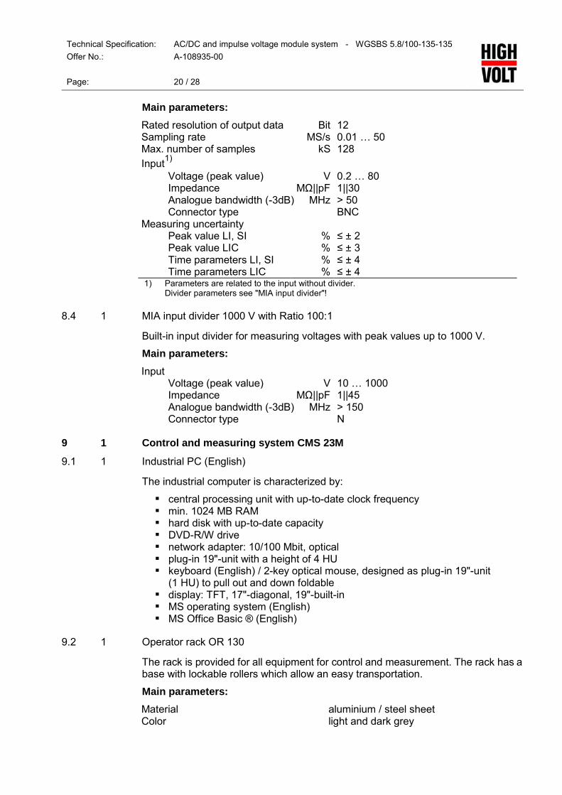
Main parameters: Rated resolution of output data Bit 12 Sampling rate MS/s 0.01 … 50 Max. number of samples kS 128 Input1) Voltage (peak value) V 0.2 … 80 Impedance MΩ||pF 1||30 Analogue bandwidth (-3dB) MHz > 50 Connector type BNC Measuring uncertainty Peak value LI, SI % ≤ ± 2 Peak value LIC % ≤ ± 3 Time parameters LI, SI % ≤ ± 4 Time parameters LIC % ≤ ± 4 1) Parameters are related to the input without divider.
Divider parameters see "MIA input divider"!
8.4 1 MIA input divider 1000 V with Ratio 100:1
Built-in input divider for measuring voltages with peak values up to 1000 V.
Main parameters: Input Voltage (peak value) V 10 … 1000 Impedance MΩ||pF 1||45 Analogue bandwidth (-3dB) MHz > 150 Connector type N
9 1 Control and measuring system CMS 23M
9.1 1 Industrial PC (English)
The industrial computer is characterized by: central processing unit with up-to-date clock frequency min. 1024 MB RAM hard disk with up-to-date capacity DVD-R/W drive network adapter: 10/100 Mbit, optical plug-in 19"-unit with a height of 4 HU keyboard (English) / 2-key optical mouse, designed as plug-in 19"-unit
(1 HU) to pull out and down foldable display: TFT, 17"-diagonal, 19"-built-in MS operating system (English) MS Office Basic ® (English)
9.2 1 Operator rack OR 130
The rack is provided for all equipment for control and measurement. The rack has a base with lockable rollers which allow an easy transportation.
Main parameters: Material aluminium / steel sheet Color light and dark grey

Technical Specification: AC/DC and impulse voltage module system - WGSBS 5.8/100-135-135
Offer No.: A-108935-00
Page: 21 / 28
Dimensions (approx.) Width mm 553 Depth mm 690 Height mm 1275 Total weight (approx.) kg 45
9.3 1 Operator device BG 8M E
The operator device is used to operate HV modular test systems. This device is a plug-in 19" -unit. It contains a SIEMENS branded operator panel which acts as a Human Machine Interface (HMI) between the operator and the test system. Manual and simple automatic test procedures can be carried out. An LCD-backlight-touch-screen ensures an easy handling of the operator device. The communication between the operator device and the test system is realized via a fiber optic link (ETHERNET) to eliminate electromagnetic interferences.
Main functions of the operator device are: emergency stop control on/off operating switch on/off voltage increases/decreases status indication of main and operating switch state messages of the test system pre-selection of test voltage and test time two pre-selectable regulating speeds limits for voltage and current for system protection password protection of essential system settings
Main parameters: Supply voltage V 230 Frequency Hz 50/60 Operating temperature °C 5 ... 35 Operating humidity (rel.) % ≤ 95, no condensation Dimensions (approx.) Width mm 462 Height mm 293 (6 HU) Depth mm 440 Weight kg 9 Interface ETHERNET, fiber optic
Fig. 26 Schematic sketch of operator device as plug-in 19"-unit

Technical Specification: AC/DC and impulse voltage module system - WGSBS 5.8/100-135-135
Offer No.: A-108935-00
Page: 22 / 28
9.4 1 Module extension for impulse voltage
This m odule i s an ex tension t o the c ontrol for impulse v oltage c onfigurations of module systems.
9.5 1 AC/DC peak voltmeter MU 18
The pea k v oltmeter M U 18 i s de signed as built-in uni t. I t i s us ed for al l measurements of AC and DC voltages especially in HVAC and HVDC test systems in connection with HV dividers.
The measured voltage is displayed on the operator device and/or control computer of the system control. All pre-selection as well as handling the measured data and the display is also done via the operator device or control computer.
Advantageous for practical measurements i s t he immediate storage of the latest value in case of a disruptive discharge at the test object.
The unit MU 18 is always built into another device of the HIGHVOLT control system.
The AC/DC peak voltmeter is in accordance with the related international standard IEC 60060-2.
The peak v oltmeter i s calibrated ac cording t o IEC 60060-2 by t he H IGHVOLT Calibration Laboratory DKD-K-24501, a ccredited by t he German C alibration Service D KD. A respective D KD c alibration certificate i s i ssued. The c ertificate documents the t raceability t o nat ional s tandards, w hich r ealize t he units of measurements according to the International System of Units (SI).
Main parameters: Input voltage V 0 … ±1000 Input impedance MΩ||pF 10||50 Frequency range Hz 10 … 500 and DC Measuring uncertainty % ≤ 0.5 Temperature range °C 5 … 40 Relative humidity % 10 … 80 Input connector coaxial, type N Divider ratio typical 1...20000; possible 1...9.999E09
9.6 1 AC secondary current measurement MI 11 W
The AC secondary current measurement will be carried out on the HV side of the HV test system.
The MI 11 W is always built into another device of the HIGHVOLT test system.
It consists o f a c urrent measuring transformer ( selected ac cording t o t he r ated current of the AC test system) and a measuring transducer. The current transformer is pl aced c lose t o t he grounded end o f the H V w inding o f t he t est o r ex citer transformer w hereas t he t ransducer i s pl aced i n t he s witchgear c ubicle / pow er module. Both are connected by a two-wire cable. The output of the transducer is processed by a programmable logic controller (PLC). The current is displayed on the operator device or IPC.

Technical Specification: AC/DC and impulse voltage module system - WGSBS 5.8/100-135-135
Offer No.: A-108935-00
Page: 23 / 28
9.7 1 DC secondary current measurement MI 11 G
The DC secondary current measurement will be carried out on the HV side of the HV test system.
The MI 11 G is always built into another device of the HIGHVOLT test system.
It consists of a current measuring shunt arranged in the ground connection of the rectifier column. It is selected according to the test equipment data. The shunt resistor is completed by related over voltage and over current protections. The output shunt i s c onnected t o a bu ffer amplifier t hat s upplies an ou tput v oltage (0 … 10 V DC) to the PLC. The current is displayed on the operator device or IPC.
9.8 1 Software for computer-aided testing WGMS 23 M
The software for computer-aided testing WGMS 23 M is designed for HV testing using the HV module system. It can control different components/sub-systems of the test system via one IPC. Supported features are: operation of the HV module test system voltage measurement check of the safety circuits; information about feedings and test circuit recording of data and printing of the protocol help functions
The advanced software WGMS 23 M enhances the performance of the test system significantly. Advanced features in this version are: software interface for hardware extensions, e.g. PD measurement full automation of test procedures template PSM 11(breakdown test according to the progressive stress
method - IEC 60060-1) template LTC 11(life-time characteristic) template WDT 11(withstand and assured discharge test according to IEC
60060-1) open interface for customer developed templates data transmitting to customer LAN via Ethernet
Remark: A pr oper oper ation o f t he s oftware c an onl y be g uaranteed i f the IPC/Laptop i s del ivered by H IGHVOLT. Otherwise Windows and M S Office are necessary requirements.
9.9 1 Software for computer-aided testing IMS 23
The software for computer-aided testing IMS 23 is designed for impulse testing. It can c ontrol di fferent c omponents/sub-systems o f the t est system via one I PC. Supported features are: operation of the HV impulse test system charging measurement controlling of switching gap controlling of chopping gap (as far as included) check of the safety circuits; information about feedings and test circuit recording of data and printing of the protocol help functions

Technical Specification: AC/DC and impulse voltage module system - WGSBS 5.8/100-135-135
Offer No.: A-108935-00
Page: 24 / 28
The advanced s oftware I MS 23 enhances t he performance o f the t est s ystem significantly. Advanced features in this version are: software interface for hardware extensions, e.g. transient measuring
system and impulse voltage measurement full automation of test procedures template MLM 21 (multiple level method) template PSM 21 (progressive stress method) template UDM 21 (up-and-down method) template WDT 21 (withstand voltage test, discharge voltage test) open interface for customer developed templates data transmitting to customer LAN via Ethernet
Remark: A pr oper oper ation o f t he s oftware c an onl y be g uaranteed i f the IPC/Laptop i s del ivered by H IGHVOLT. Otherwise Windows and M S Office are necessary requirements.
10 1 Special accessories
10.1 1 Rod for earthing ES 1
The ES 1 is designed for earthing and short-circuiting of AC test systems. The test system has to be switched off before the rod for earthing can be used. It is designed for indoor operation.
Main parameters: Dimensions (approx.) Length total (lg) mm 1125 Length handle (lh) mm 300 Length isolation (li) mm 700 Weight (approx.) kg 4
Fig. 27 Schematic sketch of ES 1
10.2 1 Rod for discharge and earthing ERS 1
The ERS 1 is designed for earthing, discharging and short-circuiting of ≤ 135 kV DC test systems. The test system has to be switched off before the rod for discharge and earthing can be used. It is designed for indoor operation.
Main parameters: Maximum energy kJ 2 Discharging resistor Ω 500 Dischargeable capacitance nF 175 Maximum discharge mC 24

Technical Specification: AC/DC and impulse voltage module system - WGSBS 5.8/100-135-135
Offer No.: A-108935-00
Page: 25 / 28
Dimensions (approx.) Length total (lg) mm 1740 Length handle (lh) mm 300 Length isolation (li) mm 700 Weight (approx.) kg 5
Fig. 28 Schematic sketch of ERS 1
10.3 1 Module for discharge and earthing ERE 150
The ERE 150 is designed for earthing, discharging and short-circuiting of ≤ 150 kV DC t est s ystems. It i s dr iven by a m agnet a nd w orks i n conjunction w ith a HIGHVOLT control module. The test system has to be switched off before the module for discharge and earthing can be used. It is designed for indoor operation.
Main parameters: Max. rated voltage DC kV 150 Maximum energy kJ 0.2 Discharging resistor Ω 1000 Dischargeable capacitance nF 20 Maximum discharge mC 3 Dimensions (approx.) Height (H) mm 840 Width (W) mm 300 Weight (approx.) kg 5
Fig. 29 Schematic sketch of ERE 150
H
W

Technical Specification: AC/DC and impulse voltage module system - WGSBS 5.8/100-135-135
Offer No.: A-108935-00
Page: 26 / 28
11 1 Miscellaneous
11.1 1 DKD-Calibration of alternating voltage measuring system
The HIGHVOLT calibration laboratory DKD-K-24501 is accredited by the German Calibration Service DKD according to DIN EN ISO/IEC 17025:2005. The DKD is signatory t o t he multilateral a greements o f the E uropean c o-operation f or Accreditation ( EA) and o f the I nternational Lab oratory A ccreditation C ooperation (ILAC) for the mutual recognition of calibration certificates.
The laboratory performs the calibration according to IEC 60060-2 by comparison measurement against reference standards.
The assigned scale factor of the measuring system is determined and it is verified if the measurement uncertainty is within the limits of ± 3 % defined in IEC 60060-2.
The measurement uncertainty is estimated according to the ISO/BIMP guide GUM ("Guide to the Expression of Uncertainty in Measurement”).
11.2 1 DKD-Calibration of direct voltage measuring system
The HIGHVOLT calibration laboratory DKD-K-24501 is accredited by the German Calibration Service DKD according to DIN EN ISO/IEC 17025:2005. The DKD is signatory t o t he multilateral a greements o f the E uropean c o-operation f or Accreditation (EA) and of t he International Lab oratory A ccreditation C ooperation (ILAC) for the mutual recognition of calibration certificates.
The laboratory performs the calibration according to IEC 60060-2 by comparison measurement against reference standards.
The assigned scale factor of the measuring system is determined and it is verified if the measurement uncertainty is within the limits of ± 3 % defined in IEC 60060-2.
The measurement uncertainty is estimated according to the ISO/BIMP guide GUM ("Guide to the Expression of Uncertainty in Measurement”).
11.3 1 DKD-Calibration of impulse voltage measuring system
The HIGHVOLT calibration laboratory DKD-K-24501 is accredited by the German Calibration Service DKD according to DIN EN ISO/IEC 17025:2005. The DKD is signatory t o t he multilateral a greements o f the E uropean c o-operation f or Accreditation (EA) and of t he International Lab oratory A ccreditation C ooperation (ILAC) for the mutual recognition of calibration certificates.
The laboratory performs the calibration according to IEC 60060-2 by comparison measurement against reference standards.
The assigned scale factor of the measuring system is determined and it is verified if the measurement uncertainty for the voltage m easurement i s w ithin t he limits of ± 3 % and for the time parameters within ± 10 % defined in IEC 60060-2.
The measurement uncertainty is estimated according to the ISO/BIMP guide GUM ("Guide to the Expression of Uncertainty in Measurement”).
11.4 1 DKD calibration certificate
About t he calibration a DKD-calibration certificate i n English language i s i ssued. The certificate documents the traceability to national standards, which realize the units of measurements according to the International System of Units (SI).

Technical Specification: AC/DC and impulse voltage module system - WGSBS 5.8/100-135-135
Offer No.: A-108935-00
Page: 27 / 28
11.5 1 DKD calibration certificate
About t he calibration a DKD-calibration certificate i n English language i s i ssued. The certificate documents the traceability to national standards, which realize the units of measurements according to the International System of Units (SI).
11.6 1 DKD calibration certificate
About t he calibration a DKD-calibration certificate i n English language i s i ssued. The certificate documents the traceability to national standards, which realize the units of measurements according to the International System of Units (SI).
11.7 1 Documentation
Technical documentation of test system will be provided in English as paper copy. The documentation will be handed over to customer's use together with handover of testing equipment.
11.8 1 Transportation packing (sea freight)
The packed good is shrink-wrapped in waterproof cover with preservation for 6 months and stackable under deck.
11.9 1 Factory acceptance test
The aim of the factory acceptance test is to demonstrate that the HV Module System under test was correctly produced and fulfils its technical specification including the relevant standards, especially IEC 60060.
The factory acceptance test is performed under the conditions of the HIGHVOLT production a nd test hal l and i s l imited ac cording t o i ts env ironmental conditions (atmospheric conditions, electric and acoustic noise level, clearances, available load, cleanness, etc.).
The factory acceptance test is used to demonstrate the operation and the handling of the HV Module System and could be considered as a first training of customer's engineers.
The test is considered to be successful if the following procedures show the proper operation:
(1) Check of the content of delivery for completeness and explanation of the test records of the main components.
(2) Explanation of the HV Module System. (3) Check o f the safety functions ( earthing dev ices, e mergency-off, s afety
circuit, overcurrent protection, etc.). (4) Demonstration and explanation of the specified voltage measuring systems
(and current measuring systems - if any) and of all other specified measuring devices, i ncluding ex planation o f the c alibration o f the v oltage measuring system(s).
(5) Check and de monstration o f the c ontrol functions, i ncluding manual a nd automatic operation (if any) as well as explanation of the operator screen of the computer control and / or of the operator device.
export
Typewritten Text

Technical Specification: AC/DC and impulse voltage module system - WGSBS 5.8/100-135-135
Offer No.: A-108935-00
Page: 28 / 28
(6) Voltage test without external load for
- AC voltage at Vrated / 15 min. - DC voltage at Vrated / 15 min for both polarities. - lightning impulse (LI) voltage at rated charging voltage (135 kV), 5
impulses for each polarity. - switching i mpulse ( SI) v oltage at r ated c harging v oltage (135 kV), 5
impulses for each polarity. (7) External breakdown test at all specified rated voltages and polarities with an
external rod gap in air and 5 breakdowns each.
The HV Module System has passed t he f actory acceptance t est if t he s ystem operates precisely.
export
Typewritten Text
export
Typewritten Text
export
Typewritten Text

Data Sheet no. 4.13/7
Spark Gaps
Description test spark gap VF 1:
The test spark gap VF 1 can be used for all module systems in the grid 850 mm. Two spheres and a spindle gear with a hand wheel for the manual adjustments of the gap spacing are located in an insulating frame. One of the electrodes is fixed and the other electrode is adjustable between 0 to 75 mm. A motor driven test spark gap VF 2 is on request available.
Note that, for the standalone installation two base elements FE1, two insulating elements IE1 and two junction elements KE1 have to be ordered as well. In the test spark gap a barrier frame can be included to demonstrate the effect of barriers. The barrier frame can hold an insulating screen, for example a sheet of paper.
Technical data:
Environmental conditions: temperature 5 to 40° C relative humidity ≤ 90 % indoor operation (different parameters on request)
type code
rated voltage AC kV
rated voltage DC and Impulse voltage
kV
dimensions (l x ød)
mm
total weight
kg
VF 1 100 135 722 x 235 5
Dimensional drawing
Fig. 1: VF 1
export
Text Box
export
Typewritten Text
export
Typewritten Text
export
Typewritten Text
export
Typewritten Text

TF 3 135 722 x 235 20
Environmental conditions: temperature 5 to 40° C relative humidity ≤ 90 % indoor operation (different parameters on request)
Dimensional drawing
Fig. 2: TF 3

Data Sheet no. 4.14/3
Test vessel, Type DG 100
Description test vessel DG 100 The pressure and vacuum test vessel serves to demonstrate the high-voltage performance in insulating gases depending on their pressure. Preferably, it is used in connection with the high-voltage module test system. Dimensions are in accordance with the reference grid 850, connection thread is M 22 x 1.5. The vessel itself is made of transparent material to observe the tests. The distance between the electrodes is adjustable. The scope of supply includes: - one set of exchangeable electrodes, consisting of semi-spherical electrodes (diameter 20 mm), rod and two
needle electrodes, - filling adapter and - manometer.
For the separate installation with PD free high-voltage connection: - one base element FE1, - one base connection element FV1, - one junction element KE1 and - one electrical connection, e.g. VE1 have to be ordered as well. Technical Data Type description: DG 100 Max. test voltage: 100 kV AC;
140 kV DC and impulse voltages Operating overpressure: 3 bar or 5 bar Volume: 4 l Temperature: 5...35°C Filling adapter: DILO ½ Inch Options - vacuum pump - SF6-gas handling device - different dimensions and electrodes upon customer’s request
export
Text Box
export
Typewritten Text
export
Typewritten Text
export
Typewritten Text


engineer
Text Box
Typical Oil Test Vessel (Cap)
"On-line PD Testing"
IPEC HHVSL PD Surveyor 2007 - Front Page
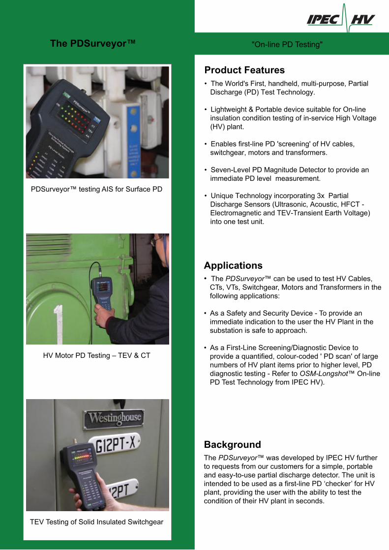
Product Features• The World's First, handheld, multi-purpose, Partial Discharge (PD) Test Technology.
• Lightweight & Portable device suitable for On-line insulation condition testing of in-service High Voltage (HV) plant.
• Enables first-line PD 'screening' of HV cables, switchgear, motors and transformers.
• Seven-Level PD Magnitude Detector to provide an immediate PD level measurement.
• Unique Technology incorporating 3x Partial Discharge Sensors (Ultrasonic, Acoustic, HFCT - Electromagnetic and TEV-Transient Earth Voltage) into one test unit.
Applications• The PDSurveyor™ can be used to test HV Cables, CTs, VTs, Switchgear, Motors and Transformers in the following applications:
• As a Safety and Security Device - To provide an immediate indication to the user the HV Plant in the substation is safe to approach.
• As a First-Line Screening/Diagnostic Device to provide a quantified, colour-coded ' PD scan' of large numbers of HV plant items prior to higher level, PD diagnostic testing - Refer to OSM-Longshot™ On-line PD Test Technology from IPEC HV).
BackgroundThe PDSurveyor™ was developed by IPEC HV further to requests from our customers for a simple, portable and easy-to-use partial discharge detector. The unit is intended to be used as a first-line PD ‘checker’ for HV plant, providing the user with the ability to test the condition of their HV plant in seconds.
The PDSurveyor™
PDSurveyor™ testing AIS for Surface PD
HV Motor PD Testing – TEV & CT
TEV Testing of Solid Insulated Switchgear

Test Set-Up with Portable Transponder(Double-Ended On-Line Cable Mapping)
"Science and Technology in Power Engineering"
IPEC HHVSL PD Surveyor 2007 - Back Page
The PDSurveyor™
How it WorksThe PDSurveyor™ units simple, 7-level, colour-coded PD level indications (displayed as a range of LEDs from green to red as shown opposite) allows very quick identification of potential insulation defects. Used in this way a large number of HV plant items can be scanned for PD activity in a fraction of the time required by other commercially available systems.
The PDSurveyor™ incorporates three individual partial discharge sensors and corresponding measurement circuits which are designed to pick up variations of PD activity in different types of HV plant, as follows:
AA – Airborne Acoustic Circuit – Acoustic PD signals are generated by partial discharges into air and are detected using the unit's 40kHz airborne acoustic sensor ('line-of-sight' to pd site required). This sensor is very useful when testing Air Insulated Switchgear.
CT - Cable PD Circuit – Cable PD is measured using an external, split-core, High Frequency Current Transformer (HFCT) sensor which is clipped around the earth strap of the cable. These pulses are generally in the frequency range of between 200kHz – 4MHz and are typically monopolar in shape. The unit measures theCable PD pulses in picoCoulombs (pC’s) by measuring the charge content (area under the monopolar pulse).
TEV Circuit – Transient Earth Voltage (TEV) PD signals are generated by internal partial discharges in switchgear, cable terminations, motors and transformers. TEV signals are in a higher frequency range of between 4MHz – 100MHz and are oscillating in general. The unithas a built-in TEV sensor which is placed against the equipment under test to measure these signals. The resultant PD signals are measured in dB (decibels), as is the convention for on-line switchgear testing.
The CT LEDs (top line) show an 'Orange 1' Cable PD Level which equates to 3300pC. The Action here wouldbe to investigate this further by PD testing with the OSM-Longshot™ On-Line PD Spot Tester.
PD Level Guidelines
PD Level Guide:
CT 300pC
600pC
1100pC
3300pC
7500pC
20000pC
50000pC
TEV
15dB
23dB
28dB
36dB
42dB
44dB
48dB
AA
12dB
18dB
20dB
22dB
25dB
28dB
33dB
Condition / Action
Plant OK/ No Action
Moderate PD/ Monitor
Moderate to High / Investigate
High PD/
Test & Restrict Access
On-Line Partial Discharge Surveying System
Testing the PD level of 33kV XLPE Cablewith a High Frequency Current Transformer
sales
Group Exporter: MULTI-TEK INTERNATIONAL 140 – 144 Freston Road (Industrial Area), London W10 6TR, England E-Mail: [email protected]


![Sin título-1 · gplithwm 02430 gp cr2430 gp cr2430 gp urwum cr2430 super value —super super high voltage (4lr44] 476 a. high voltage high voltage voltage voltage](https://static.fdocuments.us/doc/165x107/5fc9a1e0f8d7c57bb3741c3c/sin-ttulo-1-gplithwm-02430-gp-cr2430-gp-cr2430-gp-urwum-cr2430-super-value-asuper.jpg)