HIGH VOLTAGE INSTRUMENT TRANSFORMERS CA / UT / KA
22
USER MANUAL CONTENTS PRELIMINARY CONSIDERATIONS INTRODUCTION TRANSPORT AND HANDLING INSTALLATION INSPECTION AND MONITORING QUICK TROUBLESHOOTING GUIDE ANNEX I ANNEX II ANNEX III HIGH VOLTAGE INSTRUMENT TRANSFORMERS CA / UT / KA
Transcript of HIGH VOLTAGE INSTRUMENT TRANSFORMERS CA / UT / KA

USER MANUAL
CONTENTSPRELIMINARY CONSIDERATIONS
INTRODUCTION
TRANSPORT AND HANDLING
INSTALLATION
INSPECTION AND MONITORING QUICK
TROUBLESHOOTING GUIDE
ANNEX I
ANNEX II
ANNEX III
HIGH VOLTAGE INSTRUMENT TRANSFORMERS
CA / UT / KA

1 High Voltage Instrument Transformers | CA/UT/KA
User Manual
OBSERVATIONS/
Keep the instruction manual in a safe and accessible place to ensure that any operation or maintenance task can be performed quickly and easily when necessary.
For safety reasons, only qualifi ed staff can use this equipment.
Read the instruction manual and other documentation before the equipment’s installation, commissioning and maintenance.
Become familiar with all equipment information and safety precautions before using the equipment and during its operation.
Always use the equipment within the guidelines indicated in the instruction manual and other relevant documents.
In order to prevent malfunctions, carry out proper controls and maintenance.
Do not use or handle the equipment in a manner contrary to what is expressly stated in this manual, do not modify the equipment with parts from other manufacturers. This behavior can lead to damage to the equipment and/or personal injury.
ARTECHE is not liable for accidents due to causes unrelated to our guidelines.
In the event of equipment malfunction or any other type of problem, communicate it immediately to the corresponding ARTECHE department, providing the following information:
› Evaluation of contents and the product’s nameplate (name, serial number, type and date of manufacture).
› Description of the problem (as detailed as possible, including the situation immediately before and after the problem occurred) and supporting photos or videos.
If you have any questions, please contact ARTECHE www.arteche.com › EMEA: [email protected]
› APAC: [email protected]
› NAM: [email protected]
› LATAM: [email protected]
PRELIMINARY CONSIDERATIONS
ENVIRONMENTAL CONSIDERATIONS/
Disposal considerations:
Disposal or recycling will be carried out in accordance with current legislation. Oil and impregnated products shall be disposed of through an authorized manager in authorized plants. They can be incinerated in suitable plants, respecting local regulations. The oil is free of PCBs and chlorinated products. More information on the oil safety data sheet. The metals are recyclable (copper, steel, aluminum, silver, etc.).
Measures to be taken in the event of an oil spillage:
Prevent the oil from spreading or getting into the sewage system, ditches or rivers by using sand, absorbents or other appropriate barriers. Collect the oil with an absorbent material and send it to appropriate containers for disposal, in accordance with local legislation. Oil is not easily biodegradable. It contains components with bioaccumulation potential.
DANGER/CAUTION
Indicates that improper use or handling may result in physical
damage to the equipment, serious injury or even death
SAFETY PRECAUTIONS/
For safety reasons, only qualifi ed personnel can carry out maintenance and commissioning or operation.
Read the instruction manual and other documents before using the equipment. Become acquainted with every aspect of the equipment and its safety precautions before use.
Do not use, handle or modify the equipment in a way that is not expressly stated in these operating instructions and do not use or modify the equipment with parts from other manufacturers.
The safety precautions used in this manual are indicated by the following message:
Depending on the situation, mishandling can have serious repercussions, even when “Caution” is indicated in this instruction manual. Strictly observe all security measures.
These safety precautions are the manufacturer’s suggestions to ensure the safety of the equipment.
Users are requested to establish security measures so as to maintain safety and the equipment operating in accordance with various standards and requirements
ARTECHE will not be liable for accidents caused by not carrying out the safety measures.

2High Voltage Instrument Transformers | CA/UT/KA
User Manual
FOREWORD/
This manual describes the construction, installation, commissioning and monitoring for safe use of a high-voltage instrument transformer with oil-paper insulation.
INTRODUCTION
SCOPE OF APPLICATION/
The manual applies to the following transformers:
› Current Transformers, CA Series, Models: CA-36..800.
› Inductive Voltage Transformers, UT Series, Models UTx-52..525.
› Combined Transformers, KA Series, Models KA-36..245.
DESIGN/
Instrument transformers have the active parts located inside a metal enclosure located in the upper part for current transformers and in the lower part for voltage transformers.
The insulator can be either ceramic (porcelain) or polymeric (silicone), and is composed of a certain number of sheds.
The internal insulation consists of layers of paper impregnated with dielectric oil, with a relatively small volume, and hermetically sealed.
The variations in oil volume are balanced by one or more stainless steel compensators located in the device’s upper enclosure. A highly visible indicator at the top shows the compensator position.
At the bottom of the transformer there is a valve for oil sampling.
The secondary terminals of the windings are located in the terminal box at the base of the transformer.
All metal parts are treated against rust and the fasteners are made of stainless steel.
1. Cover2. Oil volume compensator3. Primary terminal4. Core(s)5. Primary winding
6. Secondary winding7. Insulator8. Capacitive bushing9. Insulating oil10. Secondary terminals
11. Tan Delta measurement tap12. Ground terminal13. Oil level indicator14. Eyebolts for lifting
› CA › KA› UTx
1
3
5
7
8
9
10
12
11
2
3
1
2
33
4
1
2
4
4 6
6
5
5
6
7
8
9
10
13
10
12 12
13
4
5
6
13
14
14 14
14
14
14 14

3 High Voltage Instrument Transformers | CA/UT/KA
User Manual
TRANSPORT/
TRANSPORT AND HANDLING
ARTECHE’s packaging guarantees a correct transport to destination.
These transformers can be transported both horizontally and vertically. For transport, the transformer should be properly attached to the packaging to avoid movement.
› Load and unload the transformer slowly and avoid sudden movements.
› It must be secured to the truck to avoid movement.
› Keep truck acceleration under 5G, and the speed under:
• Unpaved road ___________ Max. 30 km/hour
• Secondary road ___________ Max. 60 km/hour
• Highway (motorway) ___________ Max. 90 km/hour
STORAGE/
The storage area must maintain the necessary cleanliness and safety conditions so as to avoid damage to the transformer. Follow the safety markings on the packaging at all times.
› Storage in vertical position: The transformers can be stored upright in their original packaging, which was designed to this end.
› Storage in horizontal position: Transformers may only be stored horizontally within their original packaging, designed to this end. We recommend not keeping them in this position for more than 12 months. Therefore, if they are to be stored for a longer period, they should be taken out of the box and secured in an upright position. The transformer must be in an upright position for at least 2-3 days before start-up. After placing the unit in an upright position, check to see if there is residual oil in the storage area and ensure that no oil is leaking from the transformer.
Closed or semi-closed horizontal packages can be stacked at two heights if it is the same package and device. Closed or semi-closed vertical packages can only be stacked at two heights for the UTx-52..72 models. In no case can the original position of the packaging be changed.
Wooden packaging loses its properties over time, especially in outdoors. Therefore, transformers cannot be stored in their packaging indefi nitely. This period depends on the type of wood, temperature, humidity, contamination, etc. It is recommended to monitor the integrity of the packaging regularly.
After unpacking the transformers and if they are not to be installed immediately, always store them anchored fi rmly to the fl oor with no time restriction.
The fi nal holder will be responsible for delivering the used packaging or its waste for environmental management according to the legislation in force in their country.
HANDLING/
Unpacking: Remove the top and sides of the box to allow free handling of the unit.
Annex I, contains the following fi gures.
If the transformer is in a horizontal position, to place it in a vertical position, proceed as indicated in Fig. 1:
a. A wooden wedge (C) will be placed before beginning to lift it.b. During the lifting process, the slings must always be kept in
an upright position.
DANGERINJURIES from falls and tipping
› Do not place the equipment upside down or on its side
› Do not transport the equipment in conditions other than those mentioned
RECEIPT/
After receipt, check the packages for signs of shock, tampering, oil, etc. Any anomaly must be indicated on the transport company’s receipt sheet and communicated to ARTECHE or the equipment supplier.
Once the transformer has been unpacked, check that none of the screws holding the insulator have become loose during transport. If they have, tighten them according to the torque indicated in Annex II. If any other type of anomaly appears, inform ARTECHE or the supplier of the equipment. Include photos of the damaged transformers with the report.
› Possible damage to the packaging: Bumps on the outside, oil stains on the outside of the packaging, open packaging, etc.
› Possible damage to equipment: Broken or defective insulator, oil leaks, dented metal parts, damaged secondary terminal box, etc.
The packed units can be moved by forklift or with slings or chains. Follow the safety markings on the packaging.
DANGERINJURIES AND/OR FIRE
› Do not use damaged equipment
DANGER
INJURIES from falls and tipping
› Do not place the equipment upside down or on its side
› Handle the transformer according to the instructions in this manual
› The slings used must be in good condition and suitable for handling the equipment according to its weight, which is indicated on the nameplate
Under no circumstances should a transformer be manipulated by pulling on the primary terminalsThis may cause damage to the equipment and void its warranty

4High Voltage Instrument Transformers | CA/UT/KA
User Manual
INSTALLATION
Model Weight* Procedure
KA, CA >1,600 kgAccording to Fig. 4: The movements will be made by hooking the device with four slings through the four holes which are located at the base for this purpose. A sling must be fi xed at head height, hugging the lifting slings, to prevent the transformer from swinging, as indicated in Fig. 4a or in Fig. 4b.
Note: The center of gravity of the CA models is very high. The center of gravity of UT models is very low.
UTx-52..300
KA, CA <1,600 kg According to Fig. 3. The movements will be carried out by hooking the device with two slings through the two eyebolts arranged for that purpose on both sides of the head or intermediate body.UTx-420..525
*The total weight of the transformer is indicated on the nameplate
Once the equipment has been placed in an upright position, a visual inspection is suggested so as to detect possible oil leaks or stains.
Oil stains are not necessarily the result of a leak. In most cases, the stains are nothing more than oil residues left over from the manufacturing process.
The stain should be cleaned with a degreaser and the equipment should be kept under observation. If the stain reappears or spreads, contact the manufacturer.
MOUNTING ON THE STRUCTURE OR PLATFORM/Check the information on the nameplate to verify that the electrical characteristics match those of the system.
Check the status of the oil compensator’s position indicator. If the indicator is hidden, the device cannot be connected to the network, and ARTECHE or the supplier of the equipment must be informed (Fig. 5).
Some transformers have a mechanical protection for the compensator that must be removed before installation (Fig. 6). If this is the case, it shall be indicated on the equipment itself by means of a label.
Carefully check to make sure that all four legs of the device sit perfectly on the platform, before tightening the anchor screws. If this is not the case, correct the defect, by wedging metal plates or similar. Failure to do so may result in insulator breakage or oil leakage.
When the device is in a vertical position, movements can be made as indicated at Fig. 2, Fig. 3 and Fig. 4.
DANGER
INJURY AND/OR FIRE
› Do not install the equipment without following our specifi cations
› Use the transformers under proper service conditions and according to specifi cations
› Do not loosen any screws or fastening nuts, it can cause oil leaks
ELECTRICAL DISCHARGE
› Do not wire or connect when the equipment is energized
› The delta-tangent measurement tap (if any) must always be grounded when the transformer is in service
› The ground terminal of the apparatus must be solidly earthed by means of a connection capable of withstanding and conducting the line’s fault current to earth
› Do not short-circuit the secondary circuit of the voltage transformer
› Do not leave the secondary circuit of the current transformer open

5 High Voltage Instrument Transformers | CA/UT/KA
User Manual
ELECTRICAL CONNECTIONS/Primary connections
The most common connector materials are copper and aluminum. They can have a tin or silver coating with so as to prevent galvanic pair corrosion and improve their contact.
Do not bring aluminum into contact with copper-based materials unless special precautions are taken.
Material Finish Cleaning
CopperCopper/Brass We recommend cleaning the contact surfaces with
a soft cloth (avoid brushing with a metal brush)Aluminum
AluminumBare
We recommended vigorously brushing the contact surfaces with a soft metal brush (preferably
stainless steel) or sandpaper, until you see the characteristic shine of the clean metalCopper/Brass
Only impregnate the contact surfaces to be used with contact grease, keeping the others clean. Remove excess grease to avoid contamination.
Tightening must be carried out using a torque wrench, as shown on the diagram plates and in Annex II.
Change of primary ratio (if applicable). In current transformers (CA) and combined (KA), depending on the model, the change of primary ratio can be done in one or both primary terminals. The position and torque of the links is indicated on the diagram
plates next to the terminal (Fig. 7) or under the protective cover (Fig. 8). Before commissioning the transformer, check and make sure that the primary connection is in the ratio corresponding to the operating current.
Secondary connections
The secondary winding(s) must be connected to earth through one of its terminals, preferably in the secondary terminal box itself.
In case of secondary with intermediate taps, the common terminal must be grounded.
Check that the secondary connections are correctly tightened and the contact surfaces are clean.
The screws of the lower cable gland cover, the block cover and the terminals must be tightened to the torque specifi ed in Annex II.
In the terminal box there is a terminal block where the secondary wires are connected.
The disposition of the terminals is indicated on the secondary marking plate on the inside of the box cover.
A faulty contact or a bad connection can lead to rapid transformer deterioration
Current transformer (CA) and current secondaries of the combined transformer (KA)
Any secondary that is not loaded must be short-circuited and grounded
The voltage between open circuit secondary terminals can reach dangerous values and can even destroy the device
Voltage transformer (UT) and voltage secondaries of the combined transformer (KA)
Any secondary that is not loaded must be left open and grounded at a single point
The current in a short-circuited secondary can reach dangerous values and can even destroy the device
Avoid excessive torque, as the connector may suff er damage such as cracks which may expand in the future and cause it to break
An inadequate torque may cause improper contact and cause the terminals to heat up during operation
CAUTION
Do not use the secondary terminal block as a stepTo make or check the primary connections, a lifting platform or a ladder should be used, maintaining the necessary safety conditions for work at height. In no case may the terminal block be used as support
Check the correct external wiring.

6High Voltage Instrument Transformers | CA/UT/KA
User Manual
Grounding
The ground terminal of the transformer must be properly connected to the ground network by a connection capable of carrying the network’s fault current. Check that the connection is tightened correctly and that the contact surfaces are clean.
The low voltage (neutral) terminal of the voltage primary winding must always be grounded when the transformer is in service (not applicable for CA). This terminal can be located inside the secondary terminal box on the side of the box or on the outside of the tank (Fig. 9.)
The tangent delta measurement tap(if it has one) must always be grounded when the transformer is in service.
If it needs to be removed, the following steps must be followed to reconnect it (only applicable for CA series):
› Check the thread conditions. If necessary, clean them and apply contact grease.
› Tighten the connection screws on the block and the base correctly, per the tightening torque specifi ed in Annex II.
› Ground connection is tested with a multimeter connected between the link and the CT base. Measurement should be done at the lowest scale and the result must be below 0.3 ohm (Fig. 10).
Always follow the Arteche Manual for instructions on transport, storage, handling and installation.ARTECHE instrument transformers do not require maintenance. There are no moving parts and no components susceptible to wear and tear, so no active maintenance is required.
However, some companies perform some monitoring operations on instrument transformers as part of a general substation maintenance program. These maintenance programs are not intended to extend the life of the units, as the measures have no impact on the state of the insulation or the performance of the units. These programs serve to know the state of the isolation, so that the user can make decisions based on the results obtained, as well as detect situations that may be causing damage to the unit.
We at Arteche, as manufacturers, do not establish any specifi c measures, since the decision depends on:
› the resources available to each user,
› the location of the instrument transformer (can be a position which is more or less critical),
› the environmental and electrical conditions that the unit must withstand at each specifi c point,
› the history of the unit,
› the specifi c types or the problematic units,
› etc.
The following inspection points are only a suggestion in case they are within the user’s maintenance policy.
1. Physical inspection:
a. Mechanical: Look for signs of impact, damage or loose parts.
b. Electrical: Check the correct state of the electrical connections.
c. Oil: Look for oil leaks and check the oil level.
2. Dielectric tests:
d. Electrical tests to evaluate the insulation of the equipment. For the test procedure, see Annex III.
3. Oil tests:
e. Tests performed on oil samples. The oil tests analyze the state of the insulating liquid and show the properties of the system in general. The transformer oil contains information on the status of the device. Therefore, analysis of used oil can provide early indications of paper deterioration, overheating points and electrical faults. This data can be useful as a guide for corrective actions which should be applied for the transformer. When taking oil samples, follow Arteche’s user manual on oil sampling. As a general rule, the transformer should be fi lled with the same amount of oil as extracted. If this is not possible, please contact with Arteche.
4. Thermographic testing:
f. Use of thermographic cameras.
INSPECTION AND MONITORING
DANGER
ELECTRIC SHOCK AND/OR INJURY
› Everything should only be carried out by personnel qualifi ed in the maintenance and verifi cation of the equipment
› Do not touch live parts
DANGER The transformer must be fi rmly grounded. A faulty or non-existent connection may cause damage, even destroying the device
7 High Voltage Instrument Transformers | CA/UT/KA
User Manual
Type Code Test ObservationsP
hysi
cal i
nsp
ecti
on
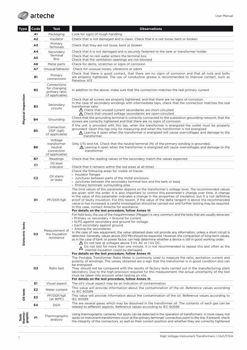
A1 Packaging Look for signs of rough handling
A2 Insulator Check that is not damaged and is clean. Check that it is not loose, bent or broken
A3 Primary Terminals Check that they are not loose, bent or broken
A4 Secondary Terminal
Box
Check that it is not damaged and is securely fastened to the tank or transformer holder
A5 Check that no rain water enters the terminal boxCheck that the ventilation openings are not blocked
A6 Metal parts Check for dents, scratches or signs of corrosion
A7 Unusual behavior Check for unusual noises, vibrations or odors
B1 Primary connections
Check that there is good contact, that there are no signs of corrosion and that all nuts and bolts are properly tightened. The use of conductive grease is recommended to improve contact, such as Penetrox A13
B2
Connections for changing primary ratio (if applicable)
In addition to the above, make sure that the connection matches the real primary current
B3 Secondary circuits
Check that all screws are properly tightened, and that there are no signs of corrosion.In the case of secondary windings with intermediate taps, check that the connection matches the real transformer ratio Check that unused current secondaries are short-circuited Check that unused voltage secondaries are open-circuited
B4 Grounding Check that the grounding terminal is correctly connected to the substation grounding network, that the screws are correctly tightened and that there are no signs of corrosion
B5Connection DDF (tgδ)
(if applicable)
If the unit is provided with this tap, when the transformer is energized the outlet must be properly grounded. Open this tap only for measuring and when the transformer is not energized Leaving it open when the transformer is energized will cause overvoltages and damage to the
transformer
B6
Voltage transformer
neutral connection
(if applicable)
Only UTx and KA. Check that the neutral terminal (N) of the primary winding is grounded. Leaving it open when the transformer is energized will cause overvoltages and damage to the
transformer
B7 Readings Check that the reading values of the secondary match the values expected
C1 Oil level indicator
Check that it remains within the red areas at all times
C2 Oil stains or leaks
Check the following areas for visible oil traces: › Insulator fl anges › Junctures between parts of the metal enclosure › Junctures between the secondary terminal box and the tank or base › Primary terminals’ surrounding area
Die
lect
ric
test
s
D1 PF/DDF/tgδ
The limit values of this parameter depend on the transformer’s voltage level. The recommended values are given with the order. It is also important to control this parameter’s change over time. A change in the value of this parameter indicates a change in the properties of insulation, but it is not defi nitive proof of faulty insulation. For this reason, if the value of the delta tangent is above the recommended value or has increased, a careful investigation should be carried out and further testing may be required. In this case, contact Arteche for assistance.For details on the test procedure, follow Annex III
D2Measurement of
the Insulation resistance
For fi eld tests, the use of the megohmmeter (Megger) is very common, and the tests that are usually done are: › Primary vs. secondary + Ground for current › N/P2 against secondary and ground for voltage › Each secondary against ground › Among the secondaries
In the case of new equipment, the value obtained does not provide any information, unless a short circuit is detected. Generally, values above 200 MΩ should be expected. However, the comparison of long-term values, as in the case of tanδ, or power factor, can help determine whether a device is still in good working order. Do not test at voltages above 3 kV AC or 1 kV DC. Do not test for more than one minute. It is not recommended to repeat this test often as the
internal insulation could be damaged. For details on the test procedure, follow Annex III
D3 Ratio test
The Portable Transformer Ratio Meter is commonly used to measure the ratio, excitation current and polarity of windings. The values obtained are a sign that the transformer is in good condition and can be energized. They should not be compared with the results of factory tests carried out in the manufacturing plant laboratory. Due to the high precision required for this measurement, the actual uncertainty of the test must be taken into account when testing on site.For details on the test procedure, follow Annex III
Oil
test
s
E1 Visual aspect The oil’s visual aspect may be an indication of contamination
E2 Water content This value will provide information about the contamination of the oil. Reference values according to IEC 60599
E3 PF/DDF/tgδ (at 90ºC)
This value will provide information about the contamination of the oil. Reference values according to IEC 60599
E4 DGA The are several gases which may be dissolved in the transformer oil. The contents of each gas can be related to diff erent aspects. Reference values according to IEC 60599
Test
s th
erm
o-gr
aphi
c
F1 Thermographic analysis
Using thermographic cameras, hot spots can be detected in the operation of transformers. In most cases, hot spots on instrument transformers occur at the primary terminals’ connection point to the line. If present, check the integrity of the connectors, as well as their correct position and whether they are correctly tightened

8High Voltage Instrument Transformers | CA/UT/KA
User Manual
TESTS PROGRAM/
When WhatOn arrival of the transformers at the warehouse or substation A1
After unpacking A2 - A3 - A4 - A6 - C2
During assembly A2 - A3 - A4 – A5 - A6 - B1 - B2 - B3 - B4 - B5 - B6 - C1 - C2 - D2 - D3
After energizing A7 - B7 - C1 - C2 - F1
Routine checks (weekly or monthly) A2 - A7 - B7 - C1 - C2
Annual check A2 - A3 - A4 - A5 - A6 - A7 - B1 - B2 - B3 - B4 - B5 - B6 - B7 - C1 - C2 - F1
Every fi ve years Same as annual + D1
After re-connections, load changes A7 - B1 - B2 - B3 - B4 - B5 - B6 - B7 - F1
After the fault conditions, the short circuits, etc. A3 - A7 - B1 - B2 - B3 - B4 - B5 - B6 - B7 - C1 - C2 - D1See also “Careful check of the transformer” below
After 1 year from start-up and after 5 years from start-up, if the values are normal and there is no considerable increase, perform an analysis after 15 years from start-up, and then every 5 years
E1 - E2 - E3 - E4
CAREFUL CHECK OF THE TRANSFORMER/It is recommended that all regular tests be repeated after a long period of operation (about 20 years), or if a major network disturbance has occurred that could damage the transformer
(e.g. a short circuit with current or duration values higher than the nominal ones, or over-voltages caused by the malfunctioning of the switches).
QUICK TROUBLESHOOTING GUIDE
Phenomenon Cause Countermeasure
Oil stains
Oil residues from the manufacturing process
Clean the area and keep it under observation for 24 hours. If the stain does not reappear, the device can function normally. If the leak persists, contact Arteche
Loose junctionsTighten the screws and bolts, clean the area and keep it under observation. If the leak persists, contact Arteche
Cracks or damage to components Contact Arteche
Oil level indicator not visible
Level indicator is stuck Remove top cover and eliminate mechanism blockage
Leakage or overpressure Remove service transformer and contact Arteche
Cracks in resin parts Bumps or improper handling Contact Arteche
User Manual - Annex I High Voltage Instrument Transformers | CA/UT/KA
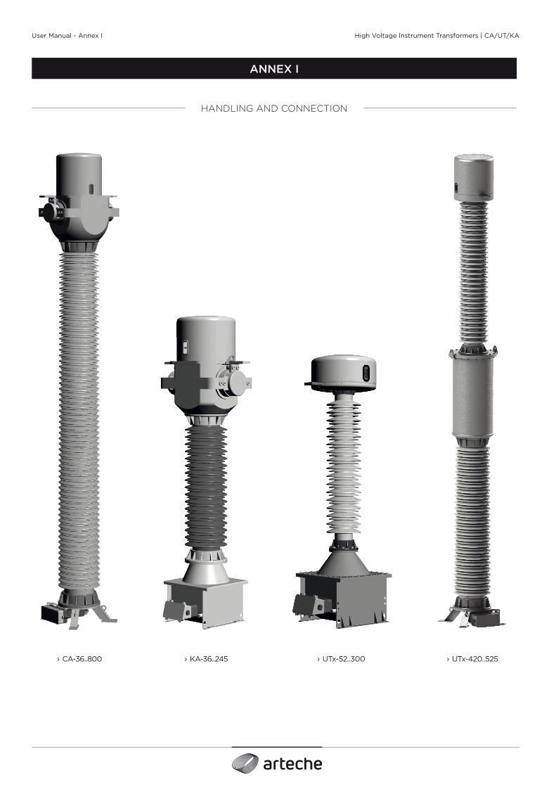
ANNEX I
› UTx-420..525› CA-36..800 › KA-36..245 › UTx-52..300
HANDLING AND CONNECTION

2
User Manual - Annex I
High Voltage Instrument Transformers | CA/UT/KA
› Fig. 1: Lifting
› UTx-420..525
› CA-36..800
› KA-36..245
› UTx-52..300
C
C
C
C

3
User Manual - Annex I
High Voltage Instrument Transformers | CA/UT/KA
› Fig. 2: Movement not allowed
› Fig. 4: Movement
› Fig. 3: Movement
› CA-36..800 › KA-36..245 › UTx-52..300 › UTx-420..525› CA-36..800
<1,600kg› KA-36..245
<1,600kg› UTx-420..525
› UTx-52..300› CA-362..800 >1,600kg
› KA-170..245 >1,600kg
› Fig. 4b
› Fig. 4a

4
User Manual - Annex I
High Voltage Instrument Transformers | CA/UT/KA
› Fig. 5: Level indicator › Fig. 6: Oil Compensator Protection
› Fig. 10: Resistance measurement tgδ tap connection
› Fig. 8: Primary diagram plate under the protective cover› Fig. 7: Primary diagram plate next to the terminal
› Fig. 9: Neutral Grounding

User Manual - Annex II High Voltage Instrument Transformers | CA/UT/KA
ANNEX II
Screw type
Torque wrench setting (Nm)
Use Torque wrench setting
M12/16/20 Fixing the insulator to the base 30 Nm
M10/12 Tangent Delta measurement tap 30 Nm
M10/12 Primary reconnection taps 30/40 Nm
M8 Secondary terminals (if they are of the screw type) 12 Nm
M10 Grounding (inside secondary terminal box) 12 Nm
M6 Cable gland 12 Nm
M8 Terminal Block Cover 20 Nm
TIGHTENING TORQUES
NOTE: If a torque diff erent from that indicated in this table is indicated on the drawing or plates of the equipment, the torque indicated on the drawing or plate must be applied.

User Manual - Annex III High Voltage Instrument Transformers | CA/UT/KA
ANNEX III
ON-SITE ELECTRICAL TESTS
All ARTECHE transformers are tested at our High Voltage laboratories, under the strictest criteria of international standards and/or under specifi c client standards/specifi cations when so requested. All of it under a thorough quality system, certifi ed under ISO 9001. However, it is normal for pre-operative tests to be performed in order to confi rm certain important equipment values. The following is a guide to the most common on-site tests and the proper way to perform them on ARTECHE brand transformers.
This annex applies to the following equipment:
› Current Transformers, CA Series, Models: CA-36..800.
› Inductive Voltage Transformers, UT Series, Models UTx-52..525.
› Combined Transformers, KA Series, Models KA-36..245*.
*For combined transformers, tests will be performed accordingly to the current and inductive voltage parts.

2 High Voltage Instrument Transformers | CA/UT/KA
User Manual - Annex III
The purpose of this test is to assess the insulation of the HV transformer.
The IEC 61869-1 standard labels this test as a special test, and mentions that “the test circuit must be agreed between the manufacturer and the customer”, and that “the dielectric dissipation factor depends on the insulation design.” The usual values are less than 0.5%.
There is no mention of this test in the IEEE C57.13 standard.
NOTE: Field testing of tanδ may be susceptible to diff erences in measured values from factory testing due to the following factors:
› The type of test equipment used and the measurement voltage level.
› Thermal conditions (high humidity, rain, pollution).
› Temperature of the test object.
› Induced voltages to the test object through other equipment.
It is recommended that the surfaces of the transformer (insulators and others) be clean, to avoid external leakage currents.
The fi eld measurement of tanδ for transformers that are already equipped with capacitive test taps (tanδ tap) can be carried out in the same manner as at the factory. In the case of other instrument transformers without tanδ tap, the base of the instrument transformer is always grounded and cannot be isolated. Therefore, it is possible that the measurement of tanδ that is carried out in the factory or in the laboratory cannot be carried out in the substation in the same manner.
Test instruments for fi eld use are usually equipped with solutions to compensate for external leakage current. The voltage test for this particular equipment is typically 10 kV for high voltage insulation and approximately 2.5 kV for low voltage insulation.
Tanδ and capacitance measurement can also be performed in the fi eld using other low voltage test bridges and a transportable high voltage test set capable of measuring voltages up to the nominal voltage. The choice and application of various test equipment is at the discretion and experience of the user.
In addition to the measurement of tanδ, the measuring equipment can usually also measure other parameters such as capacitance and power factor.
MEASUREMENT OF CAPACITANCE AND DIELECTRIC DISSIPATION FACTOR (tanδ)
› Fig. 1a
POWER SUPPLY
ELECTRODE 10 kV
MEASUREMENT ELECTRODE
› Fig. 1b › Fig. 2
MEASUREMENT ELECTRODE
POWER SUPPLY
ELECTRODE 10 kV
It is recommended that the test be carried out at a voltage of 10 kV AC.
If the device has a tanδ tap, it is recommended to perform the test through this tap.
› HV (UST) test for transformers with tanδ tap (Fig. 1):
• The test must be performed in UST (Ungrounded Specimen Test) mode.
• The power supply cable (HV) of the measuring equipment must be connected to the primary terminals P1 and P2, which are short-circuited with each other.
• The measurement cable must be connected to the tanδ tap, which should be previously disconnected from the ground (Fig. 1b).
• The secondary terminals must be short-circuited and grounded.
• Warning: At the end of the test, tanδ tap must be connected
to earth and its contact verifi ed.› HV (GST) test for transformers without tanδ tap (Fig. 2):
• The test must be performed in GST ( Ground Specimen Test) mode.
• The power supply cable (HV) of the measuring equipment must be connected to the primary terminals P1 and P2, which are short-circuited with each other.
• The measuring cable of the measuring instrument must be connected to the ground terminal, directly at the base of the instrument.
• The secondary terminals must be short-circuited and grounded.
CURRENT TRANSFORMERS/

3High Voltage Instrument Transformers | CA/UT/KA
User Manual - Annex III
It is recommended that the test be carried out at a voltage of 10 kV AC.
If the device has a tanδ tap, it is recommended to perform the test through this tap.
› HV (UST) test for transformers with tanδ tap (Fig. 3): • The test must be performed in UST (Ungrounded Specimen
Test) mode.
• The (HV) power cable of the measuring equipment must be connected to the primary terminal (A).
• The neutral connection of the primary (N*) must be disconnected from the ground and connected to the guard cable.
• The measurement cable must be connected to the tanδ tap, which should be previously disconnected from the ground.
• The corresponding secondary terminals at the end of each secondary winding must be connected to each other, and to earth.
• Warning: At the end of the test, the tanδ should be grounded and the contact should be verifi ed.
› HV (GST) test for transformers without tanδ tap (Fig. 4): • The test must be performed in GST ( Ground Specimen Test)
mode.
• The (HV) power cable of the measuring equipment must be connected to the primary terminal (A).
• The neutral connection of the primary (N*) must be disconnected from the ground and connected to the guard cable.
• The measuring cable of the measuring instrument must be connected to the ground terminal, directly at the base of the instrument.
• The corresponding secondary terminals at the end of each secondary winding must be connected to each other, and to earth.
INDUCTIVE VOLTAGE TRANSFORMERS/
› Fig. 3
A
Tanδ tapLV measuring cable
› Fig. 4
A
* The N or P2 terminal can be located inside the secondary terminal box on the side of the box or on the outside of the tank.
N N
LV measuring cable
Guard Wire - P2
Guard Wire - P2

4 High Voltage Instrument Transformers | CA/UT/KA
User Manual - Annex III
The measurement of the insulation resistance is done to check the integrity of the transformer insulation and to ensure that it has not been internally damaged during transportation.
This test depends largely on the design of the transformer, the general confi guration of the test, the instruments used, etc.
The values obtained may not be representative of the actual state of the insulation.
If this test is performed, it is recommended to contact the manufacturer.
For fi eld tests, the use of the megohmmeter (Megger) is very common, and the tests that are usually done are:
› Primary vs. secondary + Ground for current.
› N/P2 against secondary and ground for voltage.
› Each secondary against ground.
› Among the secondaries.
In the case of new equipment, the value obtained does not provide any information, unless a short circuit is detected. Generally, values above 200 MΩ should be expected. However, the comparison of long-term values, as in the case of tanδ, or power factor, can help determine whether a device is still in good working order.
Do not test at voltages above 3 kV AC or 1 kV DC.Do not test for more than one minute. It is not recommended to repeat this test often as the internal insulation could be damaged.
INSULATION RESISTANCE MEASUREMENT
› Fig. 5 › Fig. 6 › Fig. 7
Primary vs. Secondary + Ground P/S+G (Fig. 5)› The line cable of the measuring equipment must be connected
to the P1 and P2 primary terminals, which are short-circuited with each other.
› The ground wire of the measuring equipment must be connected to the short-circuited secondary wires, by the ground terminal, and directly to the base of the equipment.
› If the guard wire is used, it must be connected to the porcelain insulator.
Secondaries vs Ground S/G (Fig. 6)› The P1 and P2 Primary terminals must be disconnected.
› The line cable of the measuring equipment must be connected to the short-circuited secondary terminals.
› The ground cable of the measuring equipment must be connected to the base of the equipment.
Between secondaries S/S (Fig. 7)› This test is only applicable to transformers having more than
1 secondary.
› The P1 and P2 Primary terminals must be disconnected.
› The secondaries to be assessed will be connected; one to the line cable and the other(s) to the ground cable of the measurement equipment.
› The test is repeated with each secondary.
CURRENT TRANSFORMERS/
SUPPLYELECTRODE
GUARD ELECTRODE
GROUND ELECTRODE
GROUND ELECTRODE
GROUND ELECTRODE
SUPPLY ELECTRODE
GROUND ELECTRODE
SUPPLY ELECTRODE

5High Voltage Instrument Transformers | CA/UT/KA
User Manual - Annex III
Primaries vs. Secondaries+ Ground N/S+G (Fig. 8)› The line cable of the measuring equipment must be connected
to the terminals of the primary winding (A-N) that are short-circuited with each other, and the grounding plate (N*) must be disconnected from the primary winding.
› The ground cable of the measuring instrument must be connected to the short-circuited secondary terminals together with the ground terminals on the secondary terminal block as well as the tank.
Secondaries vs Ground S/G (Fig. 9)› Primary terminal A must be disconnected and the neutral
connection of the (N*) primary winding must be grounded.
› The line cable of the measuring equipment must be connected to the short-circuited secondary terminals.
› The grounding cable of the measuring equipment must be connected to the tank.
Between secondaries S/S› This test is only applicable to transformers having more than
1 secondary.
› Primary terminal A must be disconnected and the neutral connection of the (N*) primary winding must be grounded.
› The secondaries to be assessed will be connected; one to the line cable and the other(s) to the ground cable of the measuring equipment.
› The test is repeated with each secondary.
INDUCTIVE VOLTAGE TRANSFORMERS/
› Fig. 8 › Fig. 9
* The N or P2 terminal can be located inside the secondary terminal box on the side of the box or on the outside of the tank.
N N
A A

6 High Voltage Instrument Transformers | CA/UT/KA
User Manual - Annex III
The Portable Transformer Ratio Meter (TTR) is commonly used to measure the ratio, excitation current and polarity of windings.
The values obtained are a reference that the transformer is in good condition and can be energized. They should not be compared with the results of factory tests carried out in the manufacturing plant laboratory.
Due to the high precision required for this measurement, the actual uncertainty of the test must be taken into account when testing on site.
The TTR contains 4 terminals (this confi guration may vary depending on the manufacturer):
› H1: Black excitation terminal.
› H2: Red excitation terminal.
› X1: Black secondary terminal.
› X2: Secondary red terminal.
TRANSFORMER RATIO TEST
To carry out the test, it will be necessary to excite the transformer on the secondary side if a TTR is used, because this is where the highest number of turns are located.
This test verifi es the transformer ratio and polarity, and displays a “+” signal if correct, and a “-” signal if inverted. To carry out the test, proceed as follows (Fig. 10).
› The clamps marked “X” will be connected to the transformer’s primary terminals:
• X1 will be connected to the CT’s main terminal.
• X2 will be connected to the other primary terminal.
› The excitation terminals (the clamps marked “H”) will be connected to the transformer’s secondary terminals:
• H1 will be connected to the positive polarity terminal of the TI.
• H2 will be connected to the negative polarity terminal of the TI.
• The remaining secondaries must be short circuited.
CURRENT TRANSFORMERS/
› Fig. 10
X2
P2
X1
P1
H1
H2
7High Voltage Instrument Transformers | CA/UT/KA
User Manual - Annex III
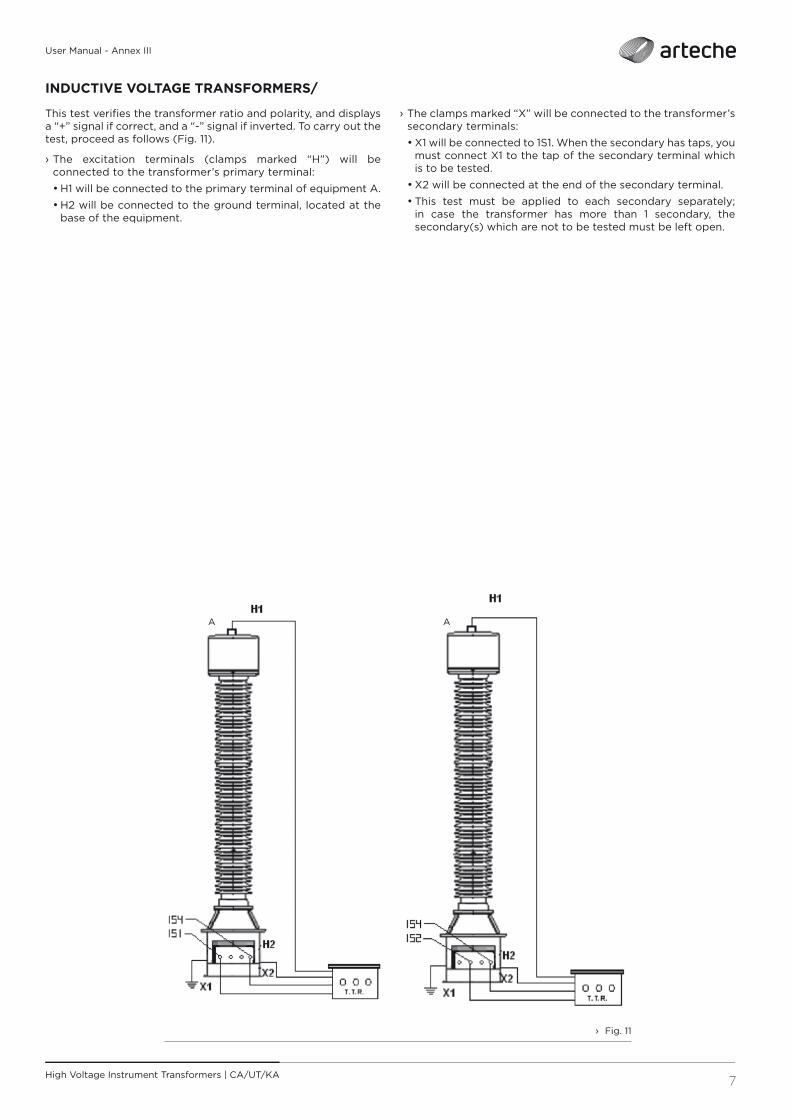
This test verifi es the transformer ratio and polarity, and displays a “+” signal if correct, and a “-” signal if inverted. To carry out the test, proceed as follows (Fig. 11).
› The excitation terminals (clamps marked “H”) will be connected to the transformer’s primary terminal:
• H1 will be connected to the primary terminal of equipment A.
• H2 will be connected to the ground terminal, located at the base of the equipment.
› The clamps marked “X” will be connected to the transformer’s secondary terminals:
• X1 will be connected to 1S1. When the secondary has taps, you must connect X1 to the tap of the secondary terminal which is to be tested.
• X2 will be connected at the end of the secondary terminal.
• This test must be applied to each secondary separately; in case the transformer has more than 1 secondary, the secondary(s) which are not to be tested must be left open.
INDUCTIVE VOLTAGE TRANSFORMERS/
› Fig. 11
A A

User Manual
For more detailed information, please visit us at arteche.com ©ARTECHESubject to change without notice
MU_HV_CA_UT_KA_ENV: A0 27/11/2020