High torque low speed vane motors (multi-torque type) MHT · 2018. 5. 10. · •switching valves...
17
3-1 N Motors (Vane) • Special switching valves enables easy switching from low speed high torque to high speed low torque. • Balanced type vane motor provides wide range of speeds and torques. • Compact with large torque output. • Smooth, stable low speeds even at 10 rpm. • Compact design which eliminates need for gear boxes and reduction gears. Functional Symbols 1 Low speed high torque vane motor 2 Full torque displacements 24, 32, 50, 70, 90, 150, 190, 250, 380, 500, 750, 1000 3 Partial torque displacements Refer to “Specifications”. 4 Shaft R1: Parallel shaft with square key (standard) 5 Design no. JA-12: MHT24, 32 15-JA: MHT70, 90 JA-30: MHT50 35-JA: MHT150, 190, 250, 380, 500, 750 (2-speed), 1000 (2-speed) JA-35: MHT750 (4-speed), 1000 (3-speed) 6 Special feature Omit: bi-directional rotation models (applied to MHT50/25/25) S12: Unidirectional right (CW) rotation (standard) S123: Unidirectional right (CW) rotation with flange type body mounting (for MHT70 and above) Note: Consult Tokyo Keiki for unidirectional left (CCW) rotation models. 7 Special switching valve Omit: no switching valve 8: Switching valve (applicable for MHT70/45/25 only) 9: Switching valve (applicable to all models except above model.) Note: Use switching valve for MHT750/625/500/375 and MHT1000/750/500. ● Special Switching Valve Refer to below for the special switching valve. MHT500/250/250-R1-35-JA-S12(9) 1 7 4 Model Code 2 6 3 5 4 Design no. Design no. is “-10-JA-S1” for MHT250, 500, 750 (2-speed) and MHT1000 (2-speed). Design no. is “JA-10-S3” for MHT750 (3-speed) and MHT1000 (3-speed). DMHT500-2-10-JA 3 2 4 1 1 Switching valve for MHT motors 2 Number 3 Motor speeds 2: 2 speed 3: 3 (or 4) speed 32 50 90 150 250 500 750 1000 MHT24 MHT32 MHT50 MHT70 MHT90 MHT150 MHT190 MHT250 MHT380 MHT500 MHT750 MHT1000 Number Applicable Motor (multi-torque) High torque low speed vane motors (multi-torque type) MHT AB B A1 A2 With special switching valve
Transcript of High torque low speed vane motors (multi-torque type) MHT · 2018. 5. 10. · •switching valves...

3-1N
Mot
ors
(Van
e)
• Special switching valves enables easy switching from low speed high torque to high speed low torque.
• Balanced type vane motor provides wide range of speeds and torques.
• Compact with large torque output.• Smooth, stable low speeds even at 10 rpm.• Compact design which eliminates need for gear boxes and reduction
gears.
Functional Symbols
1 Low speed high torque vane motor
2 Full torque displacements
24, 32, 50, 70, 90, 150, 190, 250, 380, 500, 750, 1000
3 Partial torque displacements
Refer to “Specifications”.
4 Shaft
R1: Parallel shaft with square key (standard)
5 Design no.
JA-12: MHT24, 32
15-JA: MHT70, 90
JA-30: MHT50
35-JA: MHT150, 190, 250, 380, 500, 750 (2-speed), 1000
(2-speed)
JA-35: MHT750 (4-speed), 1000 (3-speed)
6 Special feature
Omit: bi-directional rotation models (applied to MHT50/25/25)
S12: Unidirectional right (CW) rotation (standard)
S123: Unidirectional right (CW) rotation with flange type body
mounting
(for MHT70 and above)
Note: Consult Tokyo Keiki for unidirectional left (CCW) rotation models.
7 Special switching valve
Omit: no switching valve
8: Switching valve (applicable for MHT70/45/25 only)
9: Switching valve (applicable to all models except above
model.)
Note: Use switching valve for MHT750/625/500/375 and
MHT1000/750/500.
● Special Switching Valve Refer to below for the special switching valve.
MHT500/250/250-R1-35-JA-S12(9)1 74
Model Code
2 63 5
4 Design no.
Design no. is “-10-JA-S1” for MHT250, 500, 750 (2-speed) and
MHT1000 (2-speed). Design no. is “JA-10-S3” for MHT750
(3-speed) and MHT1000 (3-speed).
DMHT500-2-10-JA32 41
1 Switching valve for MHT motors
2 Number
3 Motor speeds
2: 2 speed
3: 3 (or 4) speed
呼び番号 32 50 90 150 250 500 750 1000
適用モータ(マルチトルク形)
MHT24MHT32
MHT50MHT70MHT90
MHT150MHT190MHT250
MHT380MHT500
MHT750 MHT1000
Number
Applicable Motor (multi-torque)
High torque low speed vane motors (multi-torque type) MHT
専用切換弁付き
A B
B
A1 A2
With special switching valve

N3-2
Mot
ors
(Van
e)
Specifications
• 3, 4-speed types are available with other combinations than the above chart. Consult Tokyo Keiki for details.
Characteristics Curves (at 25 mm2/s) (typical examples)
Characteristics Curves (1): 7 MPa (2): 14 MPa
2-Speed Models
全トルク 全トルク 最低 最高 モータ 専用切換弁
MHT24/12/12 JA-12 298 33 400 55 13
MHT32/16/16 JA-12 398 44 400 55 13
MHT50/25/25 JA-30 620 69 350 95 24
MHT70/35/35 15-JA 868 97 300 110 26.5
MHT90/45/45 15-JA 1116 124 300 110 26.5
MHT150/75/75 35-JA 1860 207 250 165 30
MHT190/95/95 35-JA 2360 263 200 240 38
MHT250/125/125 35-JA 3100 346 200 240 38
MHT380/190/190 35-JA 4720 526 200 335 39
MHT500/250/250 35-JA 6200 690 200 335 39
MHT750/375/375 35-JA 9300 1040 100 420 40
MHT1000/500/500 35-JA 12400 1380 75 505 41
MHT70/45/25 15-JA 868 97 300 110 26.5
MHT1000/750/500 JA-35 12400 1380 150 560 81
MHT750/625/500/375 JA-35 9300 7750 4650 1040 860 520 14 10 150 470 79690
48.5
34.5
22
173
131
104
62
690
520
分割トルク分割トルク
149
199
14 10
3段変速形
4段変速形
62 34.5
1040 690
6200
558 310
9300 6200
3100
4650
1180
6200
1550
2360
回転数
min-1差圧0.7 MPaでの
理論トルクN・m
質 量kg
10
最高使用圧力MPa
14
263
345
2段変速形
16.5
形 式
930
558
押しのけ容積
cm3/rev
434
310
デザイン番 号
Model Code
Max. Working Pressure
MPa
Speedmin-1
Weightkg
Displacementcm3/rev
Theoretical Torque (Pressure Differential 0.7 MPa)
N·mDesign No. Full Torque Full Torque Minimum MotorMaximum Special
Switching ValvePartial Torque
2-Speed Models
3-Speed Models
4-Speed Models
Partial Torque
分割トルク
(MHT16)理論流入量(MHT16)
(MHT12)
②
理論流入量 (MHT16)
(MHT16)
(MHT12)
(MHT12)
(MHT12)
①
①
②
②
②
(MHT32)
(MHT32)
(MHT24)(MHT32)
(MHT32)
(MHT24)
(MHT24)
N・m
トルク
全トルク
①
①
②
②
②
理論流入量
理論流入量
0
回転数 min-1
/L min
流入量
200 300 4001000
50500
1001000
1501500
(MHT24)②
MHT24/12/12MHT32/16/16
N・m
トルク
0
回転数 min-1
②
/
流入量
L min
100 200 3000
1001000
2002000
①
②
理論流入量
MHT50/25/25
全トルク
50
100
150
0 100 200 300
500
1000
1500
分割トルク
理論流入量
②
①
②
00
N・m
トルク
回転数 min-1
/
流入量
L min
100 200 300 400
回転数 min-1
/L min
流入量N・m
トルク
50
100
0
500
1000
Torq
ue
N·m
Torq
ue
N·m
Torq
ue
N·m
Torq
ue
N·m
Shaft Speed min-1 Shaft Speed min-1
Shaft Speed min-1Shaft Speed min-1
Full Torque
Partial Torque
Full Torque
Partial Torque
Inle
t flow
L/
min
Inle
t flow
L/
min
Inle
t flow
L/
min
Inle
t flow
L/
min
Theoretical inlet flow
Theoretical inlet flow
Theoretical inlet flow
Theoretical inlet flow
Theoretical inlet flow
Theoretical inlet flow

3-3N
Mot
ors
(Van
e)
Characteristics Curves (at 25 mm2/s) (typical examples)
Characteristics Curves (1): 7 MPa (2): 14 MPa
N・m
トルク
0
回転数 min-1
/L min
流入量
(MHT90)
(MHT90)
(MHT70)
(MHT90)
(MHT70)
(MHT90)
(MHT70)理論流入量
(MHT70)
①
②
②
②
①
②
理論流入量
100 200 3000
1001000
2002000
3003000
MHT90/45/45MHT70/35/35
全トルク
0
N・m
トルク
回転数 min-1
/
流入量
L min
理論流入量
理論流入量(MHT35)
(MHT35)
(MHT35)
(MHT45)
(MHT45)
(MHT35)
(MHT45)
(MHT45)
①
①
②
②
②
②
100 200 3000
1001000
2002000
分割トルク
minN・m
トルク
0
回転数 min-1
/L
流入量
②
100 2000
2002000
4004000
6006000
MHT150/75/75
②①
理論流入量
全トルク
0
N・m
トルク
回転数 min-1
/
流入量
L min 理論流入量
②
①
100 2000
2002000
3003000
1001000
分割トルク
②
理論流入量
(MHT250)
(MHT250)
(MHT190)理論流入量
(MHT190)
(MHT250)
(MHT190)
②
100 2000
回転数 min-1
N・m
トルク
/L min
流入量
0
2000 200
4000 400
6000 600
MHT190/95/95MHT250/125/125
全トルク
(MHT190)
(MHT250)
②
②
②
①
①
0
N・m
トルク
回転数 min-1
/
流入量
L min
理論流入量
理論流入量
(MHT125)
(MHT125)
(MHT95)
(MHT95)
(MHT125)
(MHT95)100 2000
100
2002000
4004000
300
分割トルク ②
②
①
①
N・m
トルク
0
回転数 min-1
/L min
流入量
理論流入量
理論流入量(MHT380)
(MHT380)
(MHT500)
(MHT380)
100 2000
5000 500
1000
1500
10000
15000
①
MHT380/190/190MHT500/250/250
全トルク
(MHT380)
(MHT500)
(MHT500) (MHT500)
②
②
①
②②
00
N・m
トルク
回転数 min-1
/
流入量
L min
理論流入量
②
理論流入量
②
100 200
2502500
5005000
7507500
(MHT250)
(MHT190)
(MHT190)
(MHT190)
(MHT250)
分割トルク
①
②②
①
(MHT250)(MHT250)
(MHT190)
②(MHT125)(MHT95)
②
Full Torque
Partial Torque
Partial Torque Partial Torque
Partial Torque
Full Torque
Torq
ue
N·m
Torq
ue
N·m
Shaft Speed min-1 Shaft Speed min-1
Inle
t flow
L/
min
Inle
t flow
L/
min
Theoretical inlet flow
Theoretical inlet flow
Theoretical inlet flow
Theoretical inlet flow
Theoretical inlet flowTheoretical inlet flow
Torq
ue
N·m
Torq
ue
N·m
Torq
ue
N·m
Torq
ue
N·m
Shaft Speed min-1
Shaft Speed min-1 Shaft Speed min-1
Shaft Speed min-1
Inle
t flow
L/
min
Inle
t flow
L/
min
Inle
t flow
L/
min
Inle
t flow
L/
min
Full Torque Full Torque
Torq
ue
N·m
Torq
ue
N·m
Shaft Speed min-1 Shaft Speed min-1
Inle
t flow
L/
min
Inle
t flow
L/
min
Theoretical inlet flow
Theoretical inlet flow
Theoretical inlet flow
Theoretical inlet flow
Theoretical inlet flow
Theoretical inlet flow
Theoretical inlet flow
Theoretical inlet flow

N3-4
Mot
ors
(Van
e)
Characteristics Curves (at 25 mm2/s) (typical examples)
Characteristics Curves (1): 7 MPa (2): 14 MPa
理論流入量(MHT45)
(MHT45)①
(MHT25)
(MHT25)理論流入量
(MHT25)0
/
流入量
L min
0
N・m
トルク 1000 100
2000 200分割トルク
①
②(MHT45)
(MHT45)
(MHT25)
②
②
②
min-1回転数
100 200 300
回転数
/
流入量
L minN・m
トルク
0
min-1
0
5000
10000
15000
20000
25000
1000
500
750
1250
250
全トルク
MHT1000/500/500
①
②
②
理論流入量
25 50 75
00
/
流入量
L minN・m
トルク
1000 100
2000 200
3000 300
①
②
理論流入量
②
MHT70/45/25
全トルク
min-1回転数
100 200 300
20000
10000
00
/
流入量
L minN・m①
トルク
②
1000
2000
②
理論流入量
全トルク
10050
min-1回転数
MHT750/375/375
0
/
流入量
L min
min-1回転数
50 100
500
分割トルク
①
理論流入量
②②
N・m
トルク
0
10000
5000
1000
分割トルク
①
②
理論流入量
回転数
/
流入量
L minN・m
トルク
0
min-1
0
5000
10000
15000
500
750
250
25 50 75
Full Torque
Partial Torque
Full Torque
Torq
ue
N·m
Torq
ue
N·m
Torq
ue
N·m
Shaft Speed min-1
Shaft Speed min-1
Shaft Speed min-1
Inle
t flow
L/
min
Inle
t flow
L/
min
Inle
t flow
L/
min
Theoretical inlet flow
Theoretical inlet flow
Theoretical inlet flow
Partial Torque
Torq
ue
N·m
Shaft Speed min-1
Inle
t flow
L/
min
Theoretical inlet flow
Full Torque
Torq
ue
N·m
Shaft Speed min-1
Inle
t flow
L/
min
Theoretical inlet flow
Partial Torque
Shaft Speed min-1
Torq
ue
N·m
Inle
t flow
L/
min
Theoretical inlet flow
Theoretical inlet flow

3-5N
Mot
ors
(Van
e)
Characteristics Curves (at 25 mm2/s) (typical examples)
Characteristics Curves (1): 7 MPa (2): 14 MPa
3-Speed Models 4-Speed Models
②
②
①
理論流入量
min-1回転数
10050 150
N・m
トルク
N・m
トルク
min-1回転数
理論流入量
②
①
②
10050 150
min-1回転数
50 100 1500
/
流入量
L min
0
10000
5000 500
1000
15000 1500
20000 2000
25000 2500
全トルク
MHT1000/750/500
0
/
流入量
L min
理論流入量
②
(MHT500)
(MHT750)
(MHT500)
理論流入量
②(MHT750)
0
5000 500
100010000
150015000
200020000
分割トルク
0
/
流入量
L minN・m
トルク
0
5000 500
100010000
150015000
200020000
全トルク
MHT750/625/500/375
0
min-1回転数
/
流入量
L minN・m
トルク
50 100 1500
5000 500
100010000
150015000
分割トルク
(MHT750)
(MHT500)
(MHT750)
(MHT500)①
①
②
②
理論流入量
②
(MHT500)
(MHT625)
(MHT500)
理論流入量
理論流入量
①
(MHT375)
②(MHT625)
(MHT375)
(MHT500)
②(MHT375)
①
(MHT500)
(MHT375)
(MHT625)①
②
②
②(MHT625)
Full Torque
Partial Torque Partial Torque
Full Torque
Torq
ue
N·m
Torq
ue
N·m
Torq
ue
N·m
Torq
ue
N·m
Shaft Speed min-1
Shaft Speed min-1 Shaft Speed min-1
Shaft Speed min-1
Inle
t flow
L/
min
Inle
t flow
L/
min
Inle
t flow
L/
min
Inle
t flow
L/
min
Theoretical inlet flowTheoretical inlet flow
Theoretical inlet flow
Theoretical inlet flow
Theoretical inlet flow
Theoretical inlet flow
Theoretical inlet flow

N3-6
Mot
ors
(Van
e)
Port Connection and Torque SwitchingWhen using special switching valve• Input port A, outlet port B (For left (CCW) rotation of
MHT50/25/25, inlet and outlet ports are reverse).• Switch lever only after motor is stopped. Lever should be
switched fully until it contacts stopper pin. Tighten fixing bolt.
• Lever position and torque relationship is shown in the below table.
When switching valve is not used• Select desired torque and determine port connections from
below table.• For 3-speed models (MHT70/45/25), ports should be
connected as the following table.
• Always use special switching valve for MHT750/625/500/375 and MHT1000/750/500.
• When using MHT50/25/25 with left hand rotation, the port connections shown in the above left table should be reversed.
Notes on Operation
• MountingMount motor using 4 bolt holes on the mounting flange (for MHT24, 32, 50, use 6 mounting holes on body). See dimensions for information on bolt tightening torque.
• DrainDrain should be piped directly to tank. Drain line allowable back pressure is 0.17 MPa.
• When motor is used at 3.5 MPa and under, or 50 rpm and over, confirm that drain flow is above values given in the table below. If drain flow is low, raise back pressure on motor outlet and increase drain flow.
• Rotation directionUni-directional, either right (standard) or left rotation. Motor cannot be operated in both directions (except for MHT50/25/25).Note: Consult Tokyo Keiki for left hand rotation motor.
• Motor cannot be used as brake (pump).�• Back pressure
Use a check valve, etc. to keep the motor outlet side pressure within the 0.5 to 3.5 MPa range.
• Temperature difference between motor and oil must be kept below 28°C. In any case motor is cool and oil temperature is high, run motor free from load at low speed (50min-1 or under) until the temperature difference drops within the 28°C range.
• For initial startup, fill oil from each port and operate after motor is completely filled with oil.
• See Vane Motor Notes on Operation (page N0-1).
形 式 ドレン量 cm3/min 形 式 ドレン量 cm3/min
MHT24/12/12 MHT190/95/95MHT32/16/16 MHT250/125/125MHT50/25/25 MHT380/190/190MHT70/35/35 MHT500/250/250MHT90/45/45 MHT750/375/375 570MHT150/75/75 MHT1000/500/500 760
200
200
380
Model Code Model CodeDrain cm3/min Drain cm3/min
AB
B
B B B B
B
B
A
A A A A
A
A
A
B
A
B
A
B
A
B
A
B
A
B
A
B
A
B
2速形
3速形
4速形
上記を除く2速形全て
停止低トルク中トルク高トルク最高トルク
トルクの切換状態モータ形式
MHT24/12/12MHT32/16/16
MHT70/45/25
MHT1000/750/750
MHT750/625/500/375
Motor Model
All 2 speeds models except for above model.
2-speed
3-speed
4-speed
Torque Switching Condition
Max. Torque High Torque Medium TorqueMedium Torque StopLow Torque
Torque Condition A1 Port A2 Port B PortFull Torque Low speed, high-torque Inlet Inlet
OutletPartial Torque High speed, low torque
Inlet OutletOutlet Inlet
A1
分割トルク(高速低トルク)
マルチトルク形モータ回路
B
A2
全トルク(低速高トルク)
B
A1 A2
Multi-torque motor circuit
Full torque (low speed high torque) Partial Torque (high speed low torque)
Torque Condition A1 Port A2 Port B PortFull Torque Low speed, high-torque Inlet Inlet
OutletPartial Torque
Medium speed, medium torque Outlet InletHigh speed, low torque Inlet Outlet

3-7N
Mot
ors
(Van
e)
Piping Flanges (Conforming to SAE J 518c Standard Pressure)
When using special switching valve
When switching valve is not used
• Flanges must be ordered separately.• Hex socket bolt, spring washers, O-rings included.• See page R7-1 for dimensions.
呼び ねじ形 溶接形 呼び ねじ形 溶接形
MHT24/12/12
MHT32/16/16
MHT50/25/25 FL1-10-10P-10-JA-S19-J FL1-10-10W-10-JA-S19
MHT70/35/35
MHT70/45/25
MHT90/45/45
MHT150/75/75 2 FL1-16-16P-10-JA-S4-J FL1-16-16W-10-JA 2 FL1-16-16P-10-JA-S19-J FL1-16-16W-10-JA-S19
MHT190/95/95
MHT250/125/125
MHT380/190/190
MHT500/250/250
MHT750/375/375
MHT1000/500/500
MHT750/625/500/375
MHT1000/750/500
FL1-20-20W-10-JA-S19
2-1/2
Bポート
1-1/4
1-1/2 FL1-12-12P-10-JA-S19-J FL1-12-12W-10-JA-S19
FL1-10-10W-10-JA-S21
FL1-20-20P-10-JA-S20-J FL1-20-20W-10-JA-S20
FL1-20-20P-10-JA-S19-J
FL1-20-20W-10-JA-S19
1-1/4
1-1/2
FL1-20-20P-10-JA-S19-J
2-1/2
Aポートモータ形式
FL1-20-20P-10-JA-S4-J
FL1-12-12P-10-JA-S4-J
FL1-10-10W-10-JA
FL1-12-12W-10-JA
FL1-20-20W-10-JA
フランジ形式
FL1-10-10P-10-JA-S21-J FL1-10-10P-10-JA-S4-J
Motor Model A Port B PortSize SizeThreaded ThreadedWelded Welded
Flange
呼び ねじ形 溶接形 呼び ねじ形 溶接形
MHT24/12/12
MHT32/16/16
MHT50/25/25
MHT70/35/35
MHT70/45/25
MHT90/45/45
MHT150/75/75 2 FL1-16-16P-10-JA-S4-J FL1-16-16W-10-JA
MHT190/95/95
MHT250/125/125
MHT380/190/190
MHT500/250/250
MHT750/375/375
MHT1000/500/500
A1,A2ポートモータ形式フランジ形式
1-1/2
2-1/2 FL1-20-20P-10-JA-S4-J FL1-20-20W-10-JA
Bポート
1-1/4
FL1-12-12P-10-JA-S4-J FL1-12-12W-10-JA
FL1-10-10P-10-JA-S4-J FL1-10-10W-10-JA
FL1-12-12P-10-JA-S4-J1-1/2
FL1-8-08W-10-JA
FL1-10-10W-10-JA
FL1-12-12W-10-JA
FL1-8-08P-10-JA-S4-J1
FL1-10-10P-10-JA-S4-J1-1/4
Motor Model A Port B PortSize SizeThreaded ThreadedWelded Welded
Flange

N3-8
Mot
ors
(Van
e)
MHT50/25/25-R1-JA-30
89
103
220
★
99
70
136
6-5/8-11UNC for mounting motorMounting bolt penetration depth ★Tightening torque 79±7 N•m
φ65
587
587
1106
.
.
* +0050
* ±08
+00250
.
310
5
0-0017
±01 0 -0
025 635 .
..
.
606
606
.
4-7/16-14UNC, 20.8 deep
A1 port φ31.5
302 302
4-7/16-14UNC, 28.7 deep
B port φ31.5
Parallel key
Guide hole
54
30.24-7/16-14UNC, 20.8 deep
φ125Grease inlet
Rc1/8
Drain port9/16-18UNF (SAE O-ring seal)
.
..
φ100
.
φ63
45
706
Max. 35
φ286
.
φ190475
φ1524
φ100
Max. penetration depth 5.8
15゜30゜
374
..
A2 port φ31.5
.
.
M12, 25.4 deep (for eye bolt)
.
587
φ2508
. .
.
.
158
8
.
□15 895 .
..
..
.
2059
±08* .76 .
φ152
4
φ190
475
+002
50
±08 +0
050
76±08
4-M6, 15.9 deep
..
.
MHT24/12/12-R1-JA-12-S12MHT32/16/16-R1-JA-12-S12
4949
φ60
54
108
178
89
Right (CW) rotation
★6-1/2-13UNC for mounting motorMounting bolt penetration depth ★Tightening torque 76±7 N•m
φ95
958
848
+0019-0001
.
260
5
0-0017.
881±0
1 0 -002
5.
572
.
. 262A1 port φ25.4
524
.
A2 port φ25.4
4-3/8-16UNC, 19.1 deep262
.
B port φ27
Parallel key
Guide hole
4-7/16-14UNC, 31.8 deep
φ125Grease inlet
Rc1/8Drain port7/16-20UNF (SAE O-ring seal)
629
φ57
1.
φ238
φ158, 0.4 deep
φ95
Max. penetration depth 3.4
.15゜
30゜
302
.
.
587
373 .
.
4-3/8-16UNC, 19.1 deep
.52
4
φ2032
..
133
4
.
□12 72 ..
.
..
. 1624
.
Max. 31.8+0
019
-000
1.
4-M6, 13.5 deep
φ158
, 0.4 d
eep
Dimensions
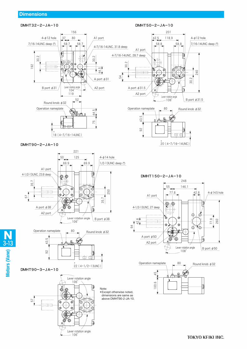
Note:• Special switching valve model,
DMHT32-2-JA-10 (see page N3-13).
Note:• * can also be used as mounting
guide holes.• Special switching valve model,
DMHT50-2-JA-10 (see page N3-13).

3-9N
Mot
ors
(Van
e)
MHT150/75/75-R1-35-JA-S123
150±15N・m
φ343251
50
127
121254
359
φ80
60
Right (CW) rotation
.72
1
699
699
1409
.
+030
. 0-0017 1096
635
177
814
92
.
357
A1 port φ38
A2 port φ38
4-1/2-13UNC27, deep
Parallel key
22
.
635
B port φ50
4-1/2-13UNC, 27 deep
4-1/2-13UNC, 27 deep
428
2-φ24 mounting bolt hole
Drain port (w/fitting)
Rc1/2
2-ø21 hole, M24 mounting bolt hole
φ125
.
Tightening torque (M20)
14
574
5
φ210
.
φ63
450 -0
025
7045
±01
φ395
φ443
48 20
+0250.
O-ring groove width
φ2785
O-ring groove diameter
゜20
゜2040゜
40゜
437
..
721
.
..
357
. .
778
M12, 25.4 deep (for eye bolt)
96 . .
. .59851□
.
0 -004
6
..
..
.
+003
9+0
001
.
..
.
MHT70/35/35-R1-15-JA-S123MHT90/45/45-R1-15-JA-S123MHT70/45/25-R1-15-JA-S123
227
320
95
φ70
φ110
50
22699
Right (CW) rotation58
758
71129
578 1236
.
+0250
. .
.
.
φ205
5
..
.
302 .
B port φ38
M12, 25.4 deep (for eye bolt)22
.
4-7/16-14UNC, 20.8 deep
Parallel key
..
A1 port φ31.5
2-φ24 mounting bolt hole
Drain port (w/fitting)
Rc1/4Tightening torque (M20)
150±15N・m
.
φ180
0 -004
..
..
5
.φ408
. .
O-ring groove diameter
.
O-ring groove width
φ360φ305
20゜
20゜
30゜
30゜
2-ø21 hole, M24 mounting bolt hole
412
.
644
644
..
A2 port φ31.5
302
.
. .
4-7/16-14UNC, 20.8 deep
357
4-1/2-13UNC, 23.8 deep
699
96 .
φ278 5+030
0-0025□15895
.
7045
φ63
45
±01
0 -002
5
574
635
+003
50 .
5515
88
133
4
Dimensions
Note:• Shaft side end-face O-ring (AS568-450),
1 pc, is included.• Special switching valve for 2-speed
model is DMHT90-2-JA-10. Special switching valve for 3-speed model is DMHT90-3-JA-10. (see page N3-13).
Note:• Shaft side end-face O-ring
(AS568-450), 1 pc, is included.
• Special switching valve model, DMHT150-2-JA-10 (see page N3-13).

N3-10
Mot
ors
(Van
e)
MHT380/190/190-R1-35-JA-S123MHT500/250/250-R1-35-JA-S123
φ3941/2-13UNC, 25.4 deep
151
57
103
225
268
411
118168
127
φ105
Right (CW) rotation
..
..
2776
889
1949
.
.
. 0-002
.
±01
0 -002
5
.
.
171
5.
A1 port φ38
A2 port φ38
30
.
681
M12, 25.4 deep (for eye bolt)
B port φ51
4-1/2-13UNC, 26.9 deep
508.
4-φ26 mounting bolt hole
Drain port (w/fitting)
Rc3/4
φ160
3
Tightening torque (M24)
250±25N・m
574
5
φ101
55
112
8
φ310
120
40
. +040
O-ring groove diameter
+0250.
O-ring groove width
φ500
30゜
30゜
357 .
699
699
823
823
4-1/2-13UNC, 26.9 deep
Parallel key
357
. .
4-1/2-13UNC, 35.1 deep
.
3897
.
112
5
96 .
φ3546 .
□2542 .
0 -005
2
..
..
.
4015
+003
80
206
2.
MHT190/95/95-R1-35-JA-S123MHT250/125/125-R1-35-JA-S123
φ394
225
268
151
57
411
φ105
298
108
3
118
Right (CW) rotation
699
699
.
1744
.
1949
.
. 0-002 1556
.
.
.
. 206
2.
.
.
A1 port φ38
A2 port φ38
.
681
30
B port φ51
4-1/2-13UNC, 26.9 deep
508
4-φ26 mounting bolt hole
Drain port (w/fitting)
Rc3/4
φ160
Tightening torque (M24)
125±15N・m
5
.
..
40 120
φ500
+0250.
O-ring groove widthφ3546+04
0
O-ring groove diameter
φ310
30゜
30゜
357 .
823
.82
3
..
4-1/2-13UNC, 26.9 deep
Parallel key
357
. .
4-1/2-13UNC, 35.1 deep
889
M12, 25.4 deep (for eye bolt)
3897
.
112
5
96 .
. .
.□ .54222
0 -005
2
987
φ88
85
±01
0 -002
5
574+0
038
0
171
5.
Dimensions
Note:• Shaft side end-face O-ring
(AS568-456), 1 pc, is included.
• Special switching valve model, DMHT250-2-10-JA-S1 (see page N3-14).
Note:• Shaft side end-face O-ring
(AS568-456), 1 pc, is included.
• Special switching valve model, DMHT500-2-10-JA-S1 (see page N3-14).

3-11N
Mot
ors
(Van
e)
2-□
φ394
φ105
300582
127
168Right (CW) rotation
MHT750/625/500/375-R1-JA-35-S123
16-1/2-13UNC, 26.9 deep
2854 1711. .
699
.82
3.
823
.
681 4566
.
.
889.
. 266
8.
0-002. .
1/2-13UNC, 25.4 deep
.0 -0
25
0 -005
2.
6203
φ101
55
0 -025 .
0 -002
5
+003
80
.
171
5.
357.
57
B1 port φ52
B2 port φ38
C1 port φ38
445
C2 port φ38
508
176
.
A2 port φ38
Parallel key
A1 port φ38
Drain port (w/fitting)
Rc3/4
φ160
3
Tightening torque (M24)
375±40N・m
..
.62
03.
φ310
2542
6-1/2-13UNC, 26.9 deep
225
268
151
411
φ105
118
Right (CW) rotation
103 103
168
127
505
MHT750/375/375-R1-35-JA-S123
357 .
699
699
.82
3.
823
..
4-1/2-13UNC, 26.9 deep
Parallel key
357
. 3809.
4-1/2-13UNC, 35.1 deep
889.
3897.
1949.
112
5.
96 .
. .
.. 0-002
.
0 -002
5
. 206
217
15
0 -005
2
. ..
.
.
+003
80
..
.
57
A1 port φ38
A2 port φ38
681
30
.
M12, 25.4 deep (for eye bolt)
B port φ51
4-1/2-13UNC, 26.9 deep
508
4-φ26 mounting bolt hole
φ394
φ160
Rc3/4
Drain port (w/fitting)
3
Tightening torque (M24)
375±40N・m
574
5
120
1/2-13UNC, 25.4 deep
40φ500
+0250.
O-ring groove widthφ3546+04
0
O-ring groove diameter
2-□2542
30゜
30゜
φ101
55
φ310
0 -002
5.
0 -002
5.
6203
6203
Dimensions
Note:• Shaft side end-face O-ring
(AS568-456), 1 pc, is included.
• Special switching valve model, DMHT750-3-JA-10-S3 (see page N3-14).
• Except where noted, dimensions are same as above MHT750/375/375.
• Flange surface dimensions for A1, A2, C1, and C2 ports are same.
Note:• Shaft side end-face O-ring
(AS568-456), 1 pc, is included.
• Special switching valve model, DMHT750-2-10-JA-S1 (see page N3-14).

N3-12
Mot
ors
(Van
e)
2-□
MHT1000/750/500-R1-JA-35-S123
Right (CW) rotation685
φ105
127
168 300
16-1/2-13UNC, 26.9 deep
.357
2854 2743. .
823
823
699.
681 5598
.
.
889
266
8
.
6-1/2-13UNC, 26.9 deep
.
.. 0-002
1/2-13UNC, 25.4 deep
6203
.
0 -005
2.
6203
φ101
55
0 -025 .
0 -002
5
+003
80
.
171
5.
.
A1 port φ38
.
A2 port φ38
.
176
508B2 port φ38
C2 port φ52
445
B1 port φ52
C1 port φ38
57
4-φ26 mounting bolt hole
φ394
Rc3/4
Drain port (w/fitting)
φ160
3Tightening torque (M24)
500±50N・m
..
.
φ310
.0 -0
25
2542 Parallel key
.
MHT1000/500/500-R1-35-JA-S123
Right (CW) rotation
268
225
103 103 103
484
411
118608168
127
φ105
357 .
823
823
699
699
..
4-1/2-13UNC, 26.9 deep
681.
4-1/2-13UNC, 35.1 deep
889.
3897
1949
.
.
112
5.
96+0250
φ3546+040
.
0 -005
2.
.. .
0 -002
5.
.
+003
80
. 206
217
15
..
A1 port φ38 .
57
..
A2 port φ38
151
357.30 M12, 25.4 deep (for eye bolt)
B port φ51
4-1/2-13UNC, 26.9 deep
508
4-φ26 mounting bolt hole
φ394
Drain port (w/fitting)
Rc3/4φ1
60
3
574
5
500±50N・m
Tightening torque (M24). .
O-ring groove diameter
..
O-ring groove width
φ500 40 120
2-□2542. 0-002 Parallel key
1/2-13UNC, 25.4 deep
0 -025.
6203
6203
0 -025.
30゜
30゜
φ101
55
φ310
Dimensions
Note:• Shaft side end-face O-ring
(AS568-456), 1 pc, is included.
• Special switching valve model, DMHT1000-3-JA-10-S3 (see page N3-14).
• Except where noted, dimensions are same as above MHT1000/500/500.
• Flange surface dimensions for A1, A2, C1, and C2 ports are same.
Note:• Shaft side end-face O-ring
(AS568-456), 1 pc, is included.
• Special switching valve model, DMHT1000-2-10-JA-S1 (see page N3-14).
3-13N
Mot
ors
(Van
e)
Note:• Except otherwise noted,
dimensions are same as above DMHT90-2-JA-10.
01-AJ-2-05THMD01-AJ-2-23THMD
52
75
*
7/16-14UNC deep (*)
Lever rotation angle
156
119
192
. .
445
.
4-φ12 hole.
B port φ31
Operation nameplate
Round knob φ32
18(4-7/16-14UNC)
A2 port
A port φ31
.
A1 port
.
201
240
80
92*
Lever rotation angle
54
588 588
.
A2 port
.
7/16-14UNC deep (*)
4-φ12 hole
Round knob φ32
20(4-7/16-14UNC)
Operation nameplate
A1 port
104゜
106゜
587 587
302
4-7/16-14UNC, 31.8 deep
302
.
4-7/16-14UNC, 28.7 deep
302
A port φ31.5
425 .
. .
302
B port φ31.5
445
435
37 80 . 1189
DMHT90-2-JA-10
.
Lever rotation angle
221
250
50
80
92
*
57
. .
.
A1 port
A port φ38
A2 port
22(4-1/2-13UNC)
Round knob φ32Operation nameplate
B port φ38
.
1/2-13UNC deep (*)
4-φ14 hole125
106゜
699 699
4-1/2-13UNC, 23.8 deep
357
357
435
DMHT90-3-JA-10
Lever rotation angle
Lever rotation angle
57
106゜
106゜
DMHT150-2-JA-10
80
Lever rotation angle
248
260
64
45
778 .
. .
.
A1 port
4-1/2-13UNC, 27 deep
A port φ50
A2 port
Round knob φ32Operation nameplate
B port φ50
55 .
108゜
428
428
778
100
6
1461
. 4-φ14.5 hole
Dimensions

N3-14
Mot
ors
(Van
e)
Dimensions table
Dimensions table
DMHT250-2-10-JA-S1DMHT500-2-10-JA-S1DMHT750-2-10-JA-S1DMHT1000-2-10-JA-S1
508
Lever rotation angle
45
267
98
X
.50
8
.
.
A1 port
.
A port φ60
A2 port
B port φ60
61 Y
Operation nameplate Round knob φ32
108゜
889
4-φ14.5 hole.988
4-1/2-13UNC, 28.6 deep
699
.
100
6
DMHT750-3-JA-10-S3DMHT1000-3-JA-10-S3
Lever rotation angle Lever rotation angle
8989
340
70
X
Y
45
98
6-φ14 hole587 508
..
.
A1 port
A2 port
B port φ60
2-1/2-13UNC, 27 deep C2 port
C1 portB1 port
A port φ60
Operation nameplate Round knob φ32
.
108゜
3377
..
889
889
100
6
108゜
Dimensions
形 式 X Y
DMHT250 291 177
DMHT500 394 280
DMHT750 497 383
DMHT1000 600 486
Model Code
形 式 X Y
DMHT750 572.3 513.6
DMHT1000 675.5 616.8
Model Code

3-15N
Mot
ors
(Van
e)
2-22
2-23
2-1
2-2
1-221-23
2-5
2-32-4
3-33-4
4-32-9
1-121-13
1-14
3-63-7
2-6
2-7
1-1
2-1
3-1
4-1
5-1
6-1
29
28
27
2625
24
17
1615
1819
2021
11
10
8
2-142-13
2-12
7-1
9-1
MHT24/12/12-S12MHT32/16/16-S12 (Seal kit No.: 40098042) MHT50/25/25 (Seal Kit No.: 40098043)
Construction
MHT24 to MHT32-S12MHT50
Note: For MHT50, part 3 is not used.
照号 名 称 部品番号 規 格 個数
2 玉軸受 40012193 JIS B 1521 6012ZZ 2
3 バックアップリング VA21304 4
4 Oリング 007904319 AS568-043(NBR,Hs90) 3
7 Oリング 007990619 AS568-906(NBR,Hs90) 3
9 Oリング 007901219 AS568-012(NBR,Hs90) 2
12 Xリング VP429290 2
14 Oリング 007926219 AS568-262(NBR,Hs90) 2
22 バックアップリング VA15590 2
23 Oリング 007915319 AS568-153(NBR,Hs90) 2
26 Oリング 007990419 AS568-904(NBR,Hs90) 1
No. Name
Bearing
Backup ring
O-ring
O-ring
O-ring
X-ring
O-ring
Backup ring
O-ring
O-ring
Part No. QtyStandard 照号 名 称 部品番号 規 格 個数
2 玉軸受 40012194 JIS B 1521 6013ZZ 2
4 Oリング 007904419 AS568-044(NBR,Hs90) 3
7 Oリング 007990819 AS568-908(NBR,Hs90) 3
9 Oリング 007911219 AS568-112(NBR,Hs90) 2
12 Xリング VP427689 2
14 Oリング 007926819 AS568-268(NBR,Hs90) 2
22 バックアップリング VA15596 2
23 Oリング 007923919 AS568-239(NBR,Hs90) 2
26 Oリング 007990619 AS568-906(NBR,Hs90) 1
No. Name
Bearing
O-ring
O-ring
O-ring
X-ring
O-ring
Backup ring
O-ring
O-ring
Part No. QtyStandard

N3-16
Mot
ors
(Van
e)
Construction
MHT190/95/95-S123MHT250/125/125-S123 (Seal kit No.: 40098040)
MHT750/375/375-S123 (Seal kit No.: 40098046)
MHT150/75/75-S123 (Seal kit No.: 40088603)
MHT70/35/35-S123MHT70/45/25-S123MHT90/45/45-S123 (Seal kit No.: 40098044)
MHT380/190/190-S123MHT500/250/250-S123 (Seal kit No.: 40078757)
MHT1000/500/500-S123 (Seal kit No.: 40098048)
MHT70 to MHT1000-S123
-1
-240
12
-2
-3
-4
-2
-3
-1
-1
-4
-1
-1
-1
-1
-2
-1-1
-2-2
-1-1
-1
-1
-2
-4
-2
-2
-2
-2
-2
-3
-1
-3
-2
-2
-1-1
-1
-1
-2
21
39
33
12
11
3433
3433
38
3536
37
3536
3635
3433
32
3130
12
34
56
78
9
78
310
11
1617
18
13
9
15
14
2019
2423
22
2021
21
2526
40
2728
29
3536
Note:• Schematics show MHT380, MHT500-S123.• For MHT70 to MHT250, parts 20 to 29 are not used.• For MHT750, two sets of parts 20 to 29 are used.• For MHT1000, three sets of parts 20 to 29 are used.• See page N3-17 for MHT750 (4-speed) and MHT1000 (3-speed).
MHT190MHT250
MHT380MHT500
MHT750 MHT1000
2 玉軸受 40012197 JIS B 1521 6021ZZ 2 2 2 2
3 Oリング 007925419 AS568-254(NBR,Hs90) 2 2 2 2
5 Oリング 007991019 AS568-910(NBR,Hs90) 1 1 1 1
7 Oリング 007991019 AS568-910(NBR,Hs90) 2 2 2 2
9 Oリング 007911419 AS568-114(NBR,Hs90) 2 2 2 2
11 シャフトシール VA30972 2 2 2 2
12 シール 40012880 2 2 2 2
20 シール 40012880 ― 2 4 6
21 Oリング 007911419 AS568-114(NBR,Hs90) ― 2 4 6
23 Oリング 007990619 AS568-906(NBR,Hs90) ― 1 2 3
33 バックアップリング VA21130 4 4 4 4
34 Oリング 007916119 AS568-161(NBR,Hs90) 3 3 3 3
36 Oリング 007991219 AS568-912(NBR,Hs90) 4 4 4 4
38 Oリング 007945619 AS568-456(NBR,Hs90) 1 1 1 1
個 数照号 名 称 部品番号 規 格No. Name
BearingO-ring
O-ring
O-ring
O-ring
O-ring
O-ringO-ring
Backup ring
O-ringO-ring
Shaft sealSealSeal
Part No. StandardQty
照号 名 称 部品番号 規 格 個数
2 玉軸受 40012195 JIS B 1521 6014ZZ 2
3 Oリング 007924119 AS568-241(NBR,Hs90) 2
5 Oリング 007990619 AS568-906(NBR,Hs90) 1
7 Oリング 007990619 AS568-906(NBR,Hs90) 2
9 Oリング 007911219 AS568-112(NBR,Hs90) 2
11 シャフトシール 40011705 2
12 Oリング 007927119 AS568-271(NBR,Hs90) 2
33 バックアップリング VA15592 4
34 Oリング 007915519 AS568-155(NBR,Hs90) 3
36 Oリング 007991019 AS568-910(NBR,Hs90) 3
38 Oリング 007945019 AS568-450(NBR,Hs90) 1
No. Name
Bearing
O-ring
O-ring
O-ring
O-ring
Shaft seal
O-ring
Backup ring
O-ring
O-ring
O-ring
Part No. QtyStandard 照号 名 称 部品番号 規 格 個数
2 玉軸受 40012196 JIS B 1521 6016ZZ 2
3 Oリング 007924619 AS568-246(NBR,Hs90) 2
5 Oリング 007990619 AS568-906(NBR,Hs90) 1
7 Oリング 007990619 AS568-906(NBR,Hs90) 2
9 Oリング 007911219 AS568-112(NBR,Hs90) 2
11 シャフトシール VA31071 2
12 シール 40012879 2
33 バックアップリング VA15594 4
34 Oリング 007915719 AS568-157(NBR,Hs90) 3
36 Oリング 007991219 AS568-912(NBR,Hs90) 3
38 Oリング 007945019 AS568-450(NBR,Hs90) 1
No. Name
Bearing
O-ring
O-ring
O-ring
O-ring
Shaft seal
Seal
Backup ring
O-ring
O-ring
O-ring
Part No. QtyStandard

3-17N
Mot
ors
(Van
e)
-1
41
411
23
3
340
4
4
3738
3937
38
3837
43
3534
1112
1336
3738
9
68
2625
24
26
25
24
13
13
30
29
28
9
9
6
6
8
8
27
2728
2827
13
13
9
9
3332
31
26
25
24
14
15
16
19
19
20
2021
2223
1718
13
36
12
11
1038
37
37
38
38 3837
37
98
67
56
44
43
34
43
3
12
423
4
-3
-1
-2
-2
-8-6
-7-5
-6
-6-6
-5-5
-5
-4
-2
-2
-2
-6
-8-8
-2
-4
-5
-6
-7
-7
-3
-3
-3
-2
-2
-2
-2
-2
-1
-3
-3
-4
-2
-3
-2
-2
-3-3
-5
-4
-5
-4
-1
-1
-1
-1
-2
-1
-1
-2
-1
-1
-1
-1
-4-4
-1
-1
-1
-1
-1
-3
-2
-2-2-3
-1
-4-3
-2-2
-3
-1
-1
MHT750/625/500/375-S123
MHT1000/750/500-S123
Note:• Schematics show MHT1000/750/500-S123.• For MHT750/625/500/375-S123, parts 14 to 23
are not used.
MHT750/625/500/375-S123 (シールキット番号:40088545)
MHT1000/750/500-S123 (シールキット番号:40098055)
MHT750/625/500/375 MHT1000/750/500
2 玉軸受 40012197 JIS B 6021ZZ 2 23 バックアップリング VA21130 8 84 Oリング 007916119 AS568-161(NBR,Hs90) 6 66 Oリング 007991019 AS568-910(NBR,Hs90) 5 59 Oリング 007911419 AS568-141(NBR,Hs90) 6 612 シャフトシール VA30972 2 213 シール 40012880 6 619 シール 40012880 220 Oリング 007911419 AS568-141(NBR,Hs90) 222 Oリング 007990619 AS568-906(NBR,Hs90) 132 Oリング 007990619 AS568-906(NBR,Hs90) 1 138 Oリング 007991219 AS568-912(NBR,Hs90) 8 840 Oリング 007945619 AS568-456(NBR,Hs90) 1 1
個数照号 名称 部品番号 規格No. Name
Bearing
Backup ring
O-ring
O-ring
O-ring
O-ring
O-ring
O-ring
O-ring
O-ring
Shaft seal
Seal
Seal
Part No. StandardQty
MHT750/625/500/375-S123 (Seal kit No.: 40088545)MHT1000/750/500-S123 (Seal kit No.: 40098055)