High temperature thermal energy storage systems … · MASTER THESIS High temperature thermal...
96
MASTER THESIS High temperature thermal energy storage systems based on latent and thermo-chemical heat storage Under the direction of Univ.Prof. Dipl.-Ing. Dr.techn. Markus Haider and Ao. Univ. Prof. Prof. Dipl.-Ing. Dr.techn. Heimo WALTER In the Institute for Energy and Thermodynamics (E302) Submitted in the Technischen Universität Wien Faculty of Mechanical and Industrial Engineering from Jennifer Carrasco Portaspana Matr. Nr. 1029166 Vienna, July 2011
Transcript of High temperature thermal energy storage systems … · MASTER THESIS High temperature thermal...

MASTER THESIS
High temperature thermal energy
storage systems based on latent
and thermo-chemical heat storage
Under the direction of
Univ.Prof. Dipl.-Ing. Dr.techn. Markus Haider
and
Ao. Univ. Prof. Prof. Dipl.-Ing. Dr.techn. Heimo WALTER
In the Institute for Energy and Thermodynamics (E302)
Submitted in the Technischen Universität Wien
Faculty of Mechanical and Industrial Engineering
from
Jennifer Carrasco Portaspana
Matr. Nr. 1029166
Vienna, July 2011

I
ACKNOWLEDGMENTS
I would like to thank Univ.Prof. Dipl.-Ing. Dr.techn. Markus Haider, the referee of my
Thesis and Ao. Univ. Prof. Prof. Dipl.-Ing. Dr.techn. Heimo WALTER who has helped me in the
last stage of my Master Thesis.
Also I would like to thank my family and my friends for giving me their support when I
have needed it and having the patience of listening to my complaints and problems when
something was not working. Specially I would like to thank my mother, Milagros Portaspana
Carrera, who has done everything which was in her hands to give me a good education.
Finally I would like to thank the Professor Lluis Albert Bonals because he has taught me
a good foundation in heat transfer and thermodynamics and he always makes the effort to
teach his students in the best way possible.

II
ABSTRACT
The increasing of the population and development of the different countries converts
the energy topic in one of the most important aspects of our times. The main target due to the
limited life of conventional energy sources is the achievement of a sustainable energy mix
where thermo solar energy plays an important role. One of the disadvantages of this
renewable energy is the fact that energy is not available all the time: the need of heat storage
systems appear. In this Master Thesis, a review on the work done until the moment in the
frame of latent heat and thermochemical storage systems is presented in the temperature
range from 200 to 700 ºC. Finally a design and the first calculations for the modeling of a latent
heat storage system for a laboratory device are shown.

III
CONTENT
ACKNOWLEDGMENTS………..……………………………………………………………………………………………………..I
ABSTRACT…………………………………………………………………………………………………………………………………II
CONTENT……………..………………………………………………………………………………………………………………….III
FIGURES……………………….…………………………………………………………………………………………………………..V
TABLES……………………………………………………………………………………………………..……………………………VIII
EQUATIONS……………………………………………………………………………………………………………………………..IX
REACTIONS……………………………………………………………………………………………………………………………….X
LIST OF TERMS…………………………………………………………………………………………………………………………XI
NOMENCLATURE………………………………………….………………………………………………………………………..XII
ANNEX A……………………………………………………………………………………………………………………………..XII
ANNEX B…………………………………………………………………………………………………………………………….XIII
NOMENCLATURE OF ANNEXES……………………………………………………………………………………………….XII
1. Introduction………………………………………………………………………………………………………………….……1
1.1. LATENT HEAT STORAGE……………………………………………………………………………………………….1
1.1.1. Materials to be used as PCM………………………………………………………………………….2
1.1.1.1. Properties required………………………………………………………………………………….2
1.1.1.2. Classification of the PCM……………………………………………………………………….…2
1.1.1.2.1. Inorganic salts and their eutectic mixtures………………………….………5
1.1.1.2.2. Metallics…………………………………………………………………………………..….7
1.1.2. Latent heat storage systems…………………………………………………………………………..8
1.1.2.1. Active direct systems………………………………………………………………………………..8
1.1.2.2. Active indirect systems……………………………………………………………………………..8
1.1.2.3. Passive systems…………………………………………………………………………………………9
1.1.3. Examples…………………………………………………………………………………………………………9
1.1.3.1. Active direct systems…..……………………………………………………………………………9
1.1.3.1.1. DISTOR Project……………………………………………………………………………..9
1.1.3.2. Active indirect systems…………………………………………..……………………………….16
1.1.3.2.1. Cascaded latent heat storage systems (CLHS) or multiple PCMs
method………………………………………………………………………………………16
1.1.3.2.2. PCM-based TES for Concentrated Solar Power Tower…………….….22
1.1.3.3. Passive systems………………………………………………………………………………………23
1.1.3.3.1. Combination of sensible and latent storage……………………………….23
1.1.3.4. Other studies……………………………………………………………………………..…………..25
1.1.3.4.1. PCM in solar thermal concentrating technology based on compact
linear Fresnel reflector (CLFR)…………………………………………………….25
1.1.3.4.2. Reflux heat transfer storage (RHTS)…………………………………………..28
IV
1.1.4. Conductivity enhancement……………………………………………………………………………29
1.1.4.1. Sandwich concept……………………………………………………………………………………29
1.1.4.2. PCM composite……………………………………………………………………………………….31
1.1.4.2.1. Graphite……………………………………………………………………………………..31
1.1.4.2.2. Graphite and metal foams………………………………………………………….32
1.1.4.2.3. Other conductivity enhancement approaches: Heat pipe heat
exchanger with latent heat storage……………………………………………34
1.2. THERMO-CHEMICAL STORAGE…………………………………………………………………………………..35
1.2.1. Properties required……………………………………………………………………………………….35
1.2.2. Classification of reactions………………………………………………………………………………36
1.2.3. Applications…………………………………………………………………………………………………..36
1.2.3.1. Dissociation of ammonia…………………………………………………………………………36
1.2.3.2. The steam and the carbon dioxide reforming of methane…………………….46
1.2.3.3. Dehydration/Hydration cycles………………………………………………………………..48
1.2.3.3.1. Medium temperature (200-300ºC) chemical heat storage using
mixed hydroxides……………………………………………………………………….48
1.2.3.3.2. Dehydration/Hydration cycle of Ca(OH)2/CaO…………………………….49
1.2.3.3.3. Ni-doped and undoped Mg-MgH2 materials……………………………….53
1.2.3.3.4. Mg2FeH6………………………………………………………..……………………………53
1.2.3.3.5. Dehydration/hydration cycles of salt hydrates……………………………54
1.2.3.4. Reduction and oxidation reactions………………………………………………………....54
2. DESIGN OF A LATENT HEAT STORAGE SYSTEM FOR A LABORATORY DEVICE……………………56
2.1. Modeling of the latent heat storage system…………………………………..………………………….59
2.1.1. The Classical Stefan Problem…………………………………………………………………………59
2.1.2. The finite volume model………………………………………………………………………………61
3. CONCLUSION……………………………………………………………………..…………………………………………….66
ANNEXES……………………………..…………………………………………………………………………………………………67
ANNEX A. Calculation of the convective coefficient and first dimensions………………………67
ANNEX B. Numerical model calculation………………………….………………………………………………70
REFERENCES……………………………………………………………………………………………………………………………77
V
FIGURES
Figure 1. Classification of PCM………………………………………………………..……..………………….….…..…….3
Figure 2. PCM groups with their heat of fusion and melting temperature range…..……….….……..4
Figure 3. Classification of PCM with examples of materials used……..………………………….……………5
Figure 4. Selected alkali nitrates/nitrites as PCM……………………………..…………………………….…….…..6
Figure 5. Basic concept for integration of thermal energy storage into solar termal parabolic
trough power plants using DSG technology…………………………………………………….…………….….…….10
Figure 6. Schematic of the sandwich concept using graphite foil………………………….…………………11
Figure 7. Capsules filled with NaNO3 – KNO3 used for laboratory scale test…………………….….…11
Figure 8. Single segment made of PCM/composite material used for the laboratory-scale
storage test unit. Holes are intended for steam pipes…………………………………………………….……….11
Figure 9. General view of the storage module and the system installed in the PSA DISS plant for
its evaluation………………………………………………………………………………………………………………….………12
Figure 10. Composite block of composite EG-PCM studied in [25]………………………………..…………13
Figure 11 . Sketch of the TES prototype with its dimensions……………………………………………….…..15
Figure 12. Proposal of cascaded latent heat storage with 5 PCM according to [11]…………..……16
Figure 13. Simplified flow diagram of the thermal oil test facility………………………………………..….17
Figure 14. Temperature distribution of a charging period with the scale time on the right
side…………………………………………………………………………………………………………………………………………18
Figure 15. Heat transfer oil temperature over time for four different LHS configurations…….…20
Figure 16. Multiple PCMs in LHTS unit of coaxial cylindrical tubes…………………….…….………………21
Figure 17. PCM-based TES design being developed by Terrafore……………………………….……………22
Figure 18. Overview of a three-part thermal energy storage system for DSG combining sensible
and latent heat storage………………………………………………………………………………………………………….24
Figure 19. PCM test module at the test site; left: delivery of the module; right: insulated
module……………………………………………………………………………………………………………………………..…….25
Figure 20. Heat capacity of high melting point phase change materials……………………….………..26
Figure 21. Media costs of high melting point PCM……………………………………………………….……..….26
Figure 22. Model for the charging and discharging study……………………………………….…..………….27
Figure 23. CLFR plant design incorporating LHTES…………………………………………….….…………………27
Figure 24. Schematic diagram of the RHTS concept…………………….…………………………………..……..28
Figure 25. Comparison of charge state for PCM without fins, with steel fins of different
thickness and with graphite fins……………………………………………………………………………..………..…….30
VI
Figure 26. NaNO3 PCM Storage Test Module………………….……………………………………………………..30
Figure 27. Fins for heat transfer enhancement……………………………………………………………….………30
Figure 28. Experimental device for the study of the conductivity enhancement…….………………..32
Figure 29. A heat pipe heat exchanger with latent heat thermal storage………………………….…….34
Figure 30. Receiver/reactor concept chosen for the ammonia thermo-chemical storage system
developed by ANU…………………………………………………………………………………………………………………..37
Figure 31. Conceptional system design of a solar thermal power plant using an ammonia-based
thermo-chemical closed-loop for energy conversion, storage and transport…………………………38
Figure 32. Experimental arrangement of ANU’s solar laboratory-scale closed-loop energy
transfer and storage system………………………………………………………………………………………..…………39
Figure 33. The 1 kWchem. synthesis reactor……………………………………………………………………………40
Figure 34. Ammonia dissociation reactor/receiver in operation on ANU’s 20 m2 solar
concentrator…………………………………………………………………………………………………………………………..41
Figure 35. Design of the cavity receiver with 15 kWsol solar dissociation reactor and its
assembly on ANU’s 20-m2 dish without insulation fitted…………………………………………………..….42
Figure 36. 15 kWsol ammonia dissociation receiver/reactor in operation on the ANU 20 m2
dish…………………………………………………………………………………………………………………………………………43
Figure 37. Design of the 10 kWth ammonia synthesis heat recovery reactor and heat recovery
tube assembly partially inserted in insulated containment…………………………………………………..43
Figure 38. Three receiver configurations viewed looking in to the aperture…………………..………..44
Figure 39. Sketch of the parabolic trough driven ammonia system…………………………….…………..45
Figure 40. Concepts for (a) closed and (b) open loop thermochemical heat-pipes based on
CH4/CO2 reforming and solar energy………………………………………………………………….….………………47
Figure 41. Thermal hybrid system (THS) combined with a medium-temperature chemical heat
pump and a high temperature exhaust gas from ICE, in comparison with the electric hybrid
system (EHS) currently employed in some hybrid vehicles………………………………………….….……….48
Figure 42. Scheme of the designed thermal storage prototype…..………………………………..…………50
Figure 43. Scheme of the experimental device used in [42]………….…………………………….…………..51
Figure 44. a) Indirectly heated reactor concept simulated by the DLR b) Experimental setup built
for the directly heated reactor concept…………………………………………………………………………..……..52
Figure 45. Equilibrium reaction temperature and potential energy storage density for various
oxides in air…………………………………………………………………………………………………………………………….55
Figure 46. Macro-encapsulation designing approach…………………………………………...………………..56
Figure 47. Single segment made of PCM/composite material used for the laboratory-scale
storage test unit. Holes are intended for steam pipes…………………………………………………………….57

VII
Figure 48. Laboratory device where the LHS will be installed……………………………………….…………58
Figure 49. Finite volume model…………………..…………………………………………………………………………..62
Figure 50. General node in cylindrical coordinates………………………....………………………………………63
Figure 51. Temperature profile for the unsteady state of node 8…………………………………………….65
Figure 52. Temperature profile for the unsteady state of nodes 9 and 10………………………….……65

VIII
TABLES
Table 1. Thermophysical properties of AlSi12 alloy……………………………………………………..…………….7
Table 2. Measured thermophysical properties of the different composites……………….………..….14
Table 3. Properties of the materials selected in [10]……………………………………………….………………17
Table 4. Heat storage capacities of four different storage configurations……………………….…….18
Table 5. Simulated storage capacities and mass portions to undergo a phase change between
charging and discharging………………………………………………………………………………………….……..…….19
Table 6. Cost and volume specific heat for some of the materials presented in this
section…………………………………………………………………………………………………………………………….……..20
Table 7. Assumptions made in the Classical Stefan Problem……………………………..…………………..60
IX
EQUATIONS
Equation 1. Storage capacity of a LHS system……………………………………………………….………………….1
Equation 2. Theoretical storage capacity of a latent heat storage system………………….….……....19
Equation 3. Position of the liquid-solid interface in the melting process of a semi-infinite
solid.............................................................................................................................................61
Equation 4. Temperature profile of the liquid region in the melting process of a semi-infinite
solid………………………………………………………………………………………………………………………………………..61
Equation 5. Conductivity between the i-node and the next one in the positive radial
direction………………………………………………………………………………………………………………………………….63
Equation 6. Conductivity between the i-node and the next one in the negative radial
direction………………………………………………………………………………………………………………………………….63
Equation 7. Conductivity between the i-node and the neighbor in the � direction (both
sides)……………………………………………………………………………………………………………………………………...64
Equation 8. Conductivity between the i-node and the neighbor in the z direction (either up and
down)……………………………………………………………………………………………………………………………………..64
Equation 9. Matrix solution of the unsteady state for the implicit method…………………….……….64

X
REACTIONS
1. Dissociation of ammonia………………………………………………………………………………….………..36
2. Carbon dioxide reforming of methane……………………………………….………………………..…….46
3. Steam reforming process of methane………………………………………………………….…..…………47
4. Metal oxide/water reaction…………………………………………………………………………………….…48
5. Dehydration/Hydration cycle of Ca(OH)2/CaO………………………………………….…………..…..49
6. Reversible Mg2FeH6 hydride system…………………………………………………………………………..53
7. Dehydration/hydration cycles of salt hydrates…………………………………………….…………....54
8. Reduction and oxidation reactions……………………………………………………………………………..54

XI
LIST OF TERMS
Term Acronym
Australian National University ANU
Compressed Expanded Graphite CEG
Compact Linear Fresnel Reflector CLFR
Cascaded Latent Heat Storage CLHS
Concentrated Solar Power CSP
German Aerospace Center DLR
Direct Steam Generation DSG
Expanded Natural Graphite ENG
Expanded graphite powder GFG
Heat Collector Reactor Element HCRE
Heat Transfer Fluid HTF
Internal Combustion Engine ICE
Latent Heat Storage LHS
Latent Heat Thermal Energy Storage LHTES
Multi Tower Solar Array MTSA
Natural Graphite NG
Phase Change Material PCM
Plataforma Solar de Almería PSA
Solar thermal electricity generating systems SEGS
Sensible Heat Storage SHS
Thermal Energy Storage TES
Thermal Hybrid System THS
XII
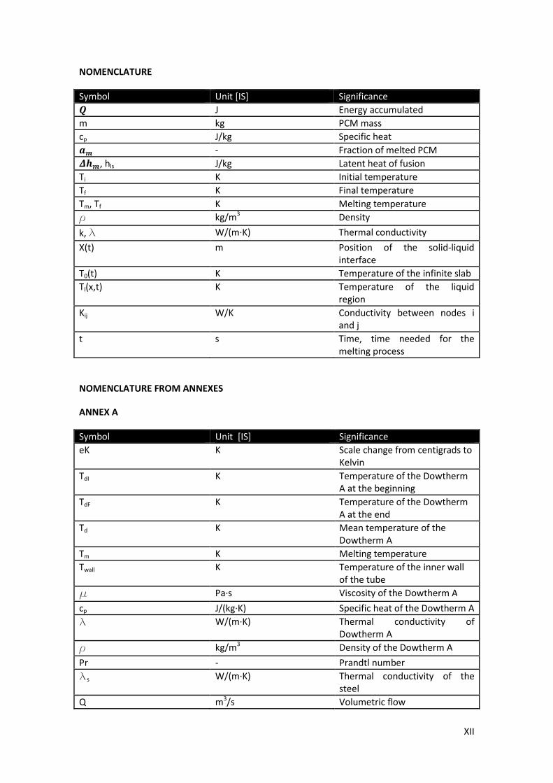
NOMENCLATURE
Symbol Unit [IS] Significance
� J Energy accumulated
m kg PCM mass
cp J/kg Specific heat
�� - Fraction of melted PCM
���, hls J/kg Latent heat of fusion
Ti K Initial temperature
Tf K Final temperature
Tm, Tf K Melting temperature
r kg/m3
Density
k, l W/(m·K) Thermal conductivity
X(t) m Position of the solid-liquid
interface
T0(t) K Temperature of the infinite slab
Tl(x,t) K Temperature of the liquid
region
Kij W/K Conductivity between nodes i
and j
t s Time, time needed for the
melting process
NOMENCLATURE FROM ANNEXES
ANNEX A
Symbol Unit [IS] Significance
eK K Scale change from centigrads to
Kelvin
TdI K Temperature of the Dowtherm
A at the beginning
TdF K Temperature of the Dowtherm
A at the end
Td K Mean temperature of the
Dowtherm A
Tm K Melting temperature
Twall K Temperature of the inner wall
of the tube
m Pa·s Viscosity of the Dowtherm A
cp J/(kg·K) Specific heat of the Dowtherm A
l W/(m·K) Thermal conductivity of
Dowtherm A
r kg/m3
Density of the Dowtherm A
Pr - Prandtl number
ls W/(m·K) Thermal conductivity of the
steel
Q m3/s Volumetric flow

XIII
Symbol Unit [IS] Significance
u m/s Velocity
Di m Inner diameter
thick m Thickness of the tube
D0 m Outer diameter
Pt m Thermal perimeter
Ph m Hydraulic perimeter
Dh m Hydraulic diameter
S m2
Inner cross-section of one tube
Afirstapprox m2 Total cross-section of the tubes
MLDT K Logarithmic mean temperature
difference
G kg/(m2·s) Superficial mass flow
Re - Reynolds number
q W/m2
Heat flux
Cfm - Friction coefficient
Nu - Nusselt number
hd W/(m2·K) Convection coefficient of the
Dowtherm A
As m2
Inner lateral area
Rs K/W Thermal resistance from the
Dowtherm A to the tube
Rss K/W Thermal resistance between the
two walls of the tube
Us W/(m2·K) Global heat transfer coefficient
Li m Length
Ai m2
Area
Vi m3
Volume
Dout m Outer diameter with the PCM
ANNEX B
Symbol Unit [IS] Significance
eK K Scale change from centigrads to
Kelvin
h W/(m2·K) Convection coefficient of the
Dowtherm A
Ts K Temperature of the steel
ls W/(m·K) Thermal conductivity of the
steel
rs kg/m3
Density of the steel
cs J/(kg·K) Specific heat of the steel
la W/(m·K) Thermal conductivity of the
aluminum
ca J/(kg·K) Specific heat of the aluminum
ra kg/m3
Density of the aluminum
XIV
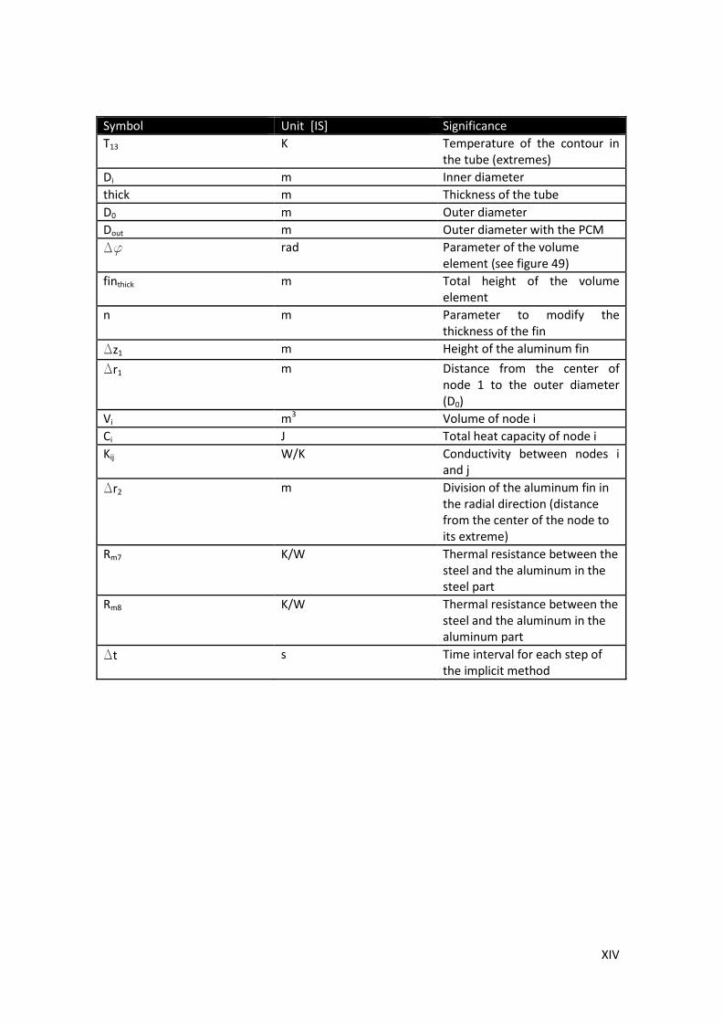
Symbol Unit [IS] Significance
T13 K Temperature of the contour in
the tube (extremes)
Di m Inner diameter
thick m Thickness of the tube
D0 m Outer diameter
Dout m Outer diameter with the PCM
Df rad Parameter of the volume
element (see figure 49)
finthick m Total height of the volume
element
n m Parameter to modify the
thickness of the fin
Dz1 m Height of the aluminum fin
Dr1 m Distance from the center of
node 1 to the outer diameter
(D0)
Vi m3
Volume of node i
Ci J Total heat capacity of node i
Kij W/K Conductivity between nodes i
and j
Dr2 m Division of the aluminum fin in
the radial direction (distance
from the center of the node to
its extreme)
Rm7 K/W Thermal resistance between the
steel and the aluminum in the
steel part
Rm8 K/W Thermal resistance between the
steel and the aluminum in the
aluminum part
Dt s Time interval for each step of
the implicit method

1
1. Introduction
The increasing on the prices of the conventional energy sources and the environmental
awareness have leaded to increase the use of renewable energies and the energy efficiency . In
this scene, storing thermal energy plays a really important role as it allows to improve the
dispatchability and the efficiency of different applications such as thermosolar power plants,
greenhouses and buildings heating systems.
There are three methods used and still being investigated in order to store thermal
energy. One is the sensible heat storage (SHS), the other one is the latent heat storage (LHS)
and the last one is the thermo-chemical storage. In the present work the last two ones will be
presented in the following sections focusing on the high temperature storage between 200
and 700 ºC.
The first method (SHS) is based on raising the temperature of a solid or liquid to store
heat and releasing it with the decrease of temperature when it is necessary. The volumes
needed to store energy in the scale that world needs are extremely large. That is why the
other two methods are being developed. The LHS method is a medium term method and the
thermo-chemical storage is a long term method as there have not been so many research work
and experiments as with the other two methods.
1.1. LATENT HEAT STORAGE
As it has been said in the introduction, an option to store thermal energy is the latent
heat storage. This method is based on the utilization of phase change materials (PCM). These
materials store heat when they go from solid to liquid, from liquid to gas or from solid to solid
(change of one crystalline form into another without a physical phase change). Then they
release energy when they have the reverse phase change. It must be mentioned that until
now, the PCM studies and applications have been mainly focused on the solid-liquid phase
change.
The storage capacity of a LHS system in the concrete case of solid-liquid
transformation is given by equation 1,
� = � � · ���
�· �� + � · �� · �ℎ� + � � · ��
��
�· ��
Equation 1. Storage capacity of a LHS system
where Ti is the initial temperature, Tm is the melting temperature, m is the mass of heat
storage medium, Cp is the specific heat, �� is the fraction melted and �ℎ� is the heat of
fusion per unit mass (J/kg).
The heat of fusion or the heat of evaporation is much greater than the specific heat.
Thanks to that, latent storage materials has got a larger volumetric energy storage capacity
than sensible storage materials. Another advantage is the fact that the absorption and release
of the energy stored takes place at a constant temperature which makes easier the choice of
the material to use in the different applications.
2
1.1.1. Materials to be used as PCM
1.1.1.1. Properties required
It is possible to find materials with a heat of fusion and melting temperature inside the
desired range but a material has to exhibit certain properties to become a feasible PCM. These
properties can be classified in 5 groups: thermal properties, physical properties, kinetic
properties, chemical properties and economical properties [1] [5].
The thermal properties the material must have:
• Suitable phase-transition temperature for the specific application.
• High latent heat of transition in order to occupy the minimum possible volume.
• High thermal conductivity in order to provide the minimum temperature gradients
and facilitate the charges and discharges of heat.
The physical properties are:
• Favorable phase equilibrium to facilitate the heat storage.
• High density to also occupy the minimum possible volume.
• Small volume change to facilitate the construction of the different needed containers
and heat exchangers.
• Low vapor pressure in order to avoid stresses and problems with the containers and
heat exchangers needed.
The kinetic properties are:
• Sufficient crystallization rate in order to avoid supercooling.
• No supercooling as it makes difficult to control the heat transfer and the truth melting
temperature that is in principle given.
The chemical properties are
• Long-term chemical stability and complete reversible melt/freeze cycle as it is needed
to work during the most cycles possible.
• Compatibility with materials of construction as it is also needed to work the most
possible time.
• No toxicity because of safety reasons.
• No fire hazard also because of safety reasons.
• Non-explosive also because of safety reasons.
Finally, from the point of view of economics, the material must be abundant, available
and cost effective to help into the feasibility of the use of the storage system.
1.1.1.2. Classification of the PCM
The different materials which have the properties mentioned before are classified in
different groups. One possible classification is the one shown in figure 1. There are three main
groups: organic materials, inorganic materials and eutectics. It must be mentioned that
generally the materials do not respect all the properties listed in the previous section and it
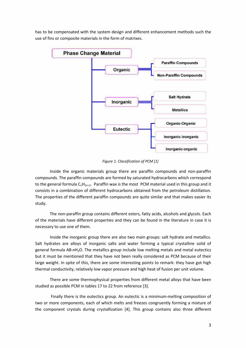
3
has to be compensated with the system design and different enhancement methods such the
use of fins or composite materials in the form of matrixes.
Figure 1. Classification of PCM [1]
Inside the organic materials group there are paraffin compounds and non-paraffin
compounds. The paraffin compounds are formed by saturated hydrocarbons which correspond
to the general formula CnH2n+2. Paraffin wax is the most PCM material used in this group and it
consists in a combination of different hydrocarbons obtained from the petroleum distillation.
The properties of the different paraffin compounds are quite similar and that makes easier its
study.
The non-paraffin group contains different esters, fatty acids, alcohols and glycols. Each
of the materials have different properties and they can be found in the literature in case it is
necessary to use one of them.
Inside the inorganic group there are also two main groups: salt hydrate and metallics.
Salt hydrates are alloys of inorganic salts and water forming a typical crystalline solid of
general formula AB·nH2O. The metallics group include low melting metals and metal eutectics
but it must be mentioned that they have not been really considered as PCM because of their
large weight. In spite of this, there are some interesting points to remark: they have got high
thermal conductivity, relatively low vapor pressure and high heat of fusion per unit volume.
There are some thermophysical properties from different metal alloys that have been
studied as possible PCM in tables 17 to 22 from reference [3].
Finally there is the eutectics group. An eutectic is a minimum-melting composition of
two or more components, each of which melts and freezes congruently forming a mixture of
the component crystals during crystallization [4]. This group contains also three different
4
groups: organic-organic, inorganic-inorganic and inorganic-organic, depending on the nature of
the components of the composition.
More detailed information about the different groups, its advantages and
disadvantages and some tables with materials of each group, melting temperature and heat of
fusion can be found in [1].
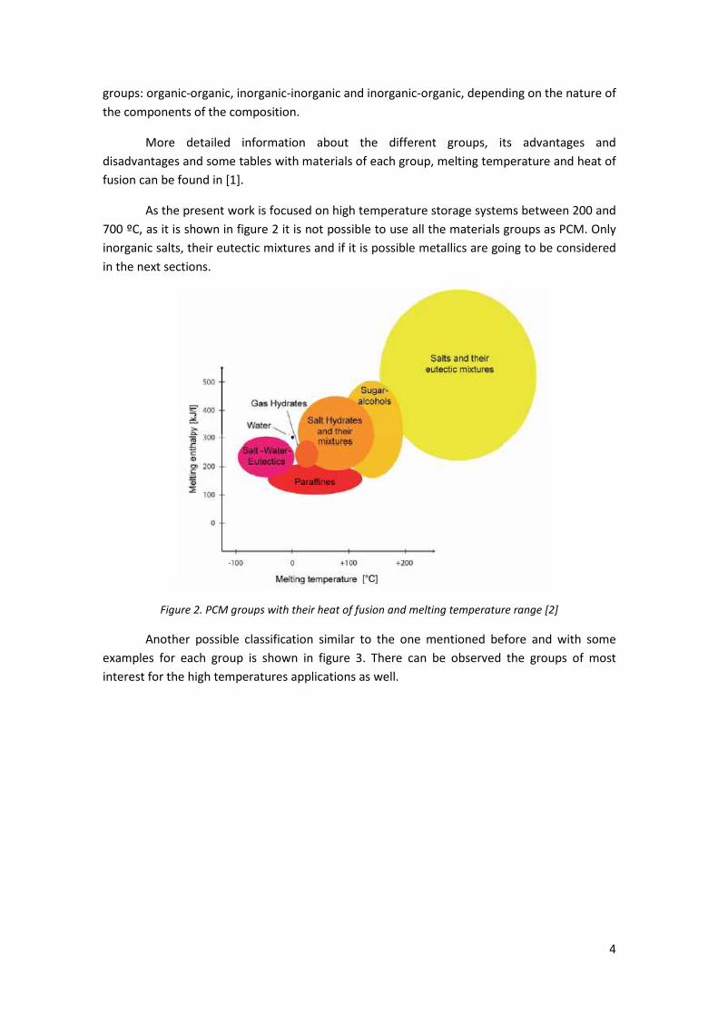
As the present work is focused on high temperature storage systems between 200 and
700 ºC, as it is shown in figure 2 it is not possible to use all the materials groups as PCM. Only
inorganic salts, their eutectic mixtures and if it is possible metallics are going to be considered
in the next sections.
Figure 2. PCM groups with their heat of fusion and melting temperature range [2]
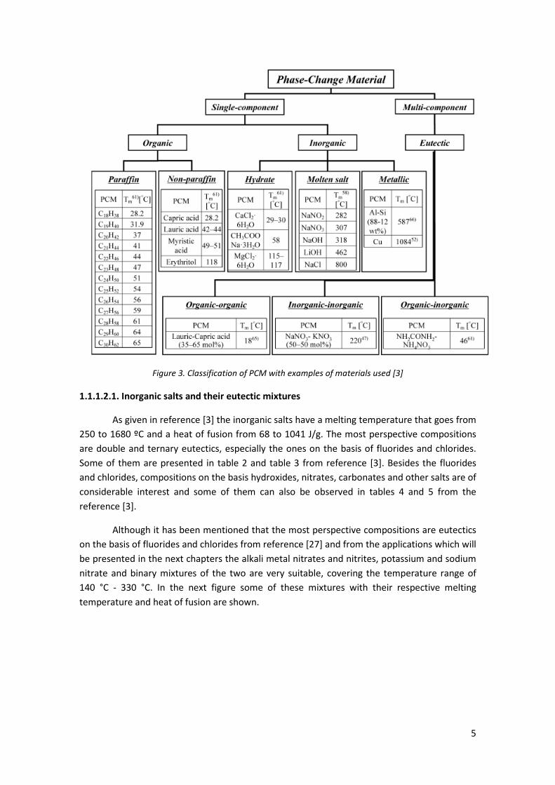
Another possible classification similar to the one mentioned before and with some
examples for each group is shown in figure 3. There can be observed the groups of most
interest for the high temperatures applications as well.
5
Figure 3. Classification of PCM with examples of materials used [3]
1.1.1.2.1. Inorganic salts and their eutectic mixtures
As given in reference [3] the inorganic salts have a melting temperature that goes from
250 to 1680 ºC and a heat of fusion from 68 to 1041 J/g. The most perspective compositions
are double and ternary eutectics, especially the ones on the basis of fluorides and chlorides.
Some of them are presented in table 2 and table 3 from reference [3]. Besides the fluorides
and chlorides, compositions on the basis hydroxides, nitrates, carbonates and other salts are of
considerable interest and some of them can also be observed in tables 4 and 5 from the
reference [3].
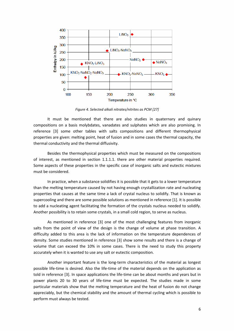
Although it has been mentioned that the most perspective compositions are eutectics
on the basis of fluorides and chlorides from reference [27] and from the applications which will
be presented in the next chapters the alkali metal nitrates and nitrites, potassium and sodium
nitrate and binary mixtures of the two are very suitable, covering the temperature range of
140 °C - 330 °C. In the next figure some of these mixtures with their respective melting
temperature and heat of fusion are shown.
6
Figure 4. Selected alkali nitrates/nitrites as PCM [27]
It must be mentioned that there are also studies in quaternary and quinary
compositions on a basis molybdates, vanadates and sulphates which are also promising. In
reference [3] some other tables with salts compositions and different thermophysical
properties are given: melting point, heat of fusion and in some cases the thermal capacity, the
thermal conductivity and the thermal diffusivity.
Besides the thermophysical properties which must be measured on the compositions
of interest, as mentioned in section 1.1.1.1. there are other material properties required.
Some aspects of these properties in the specific case of inorganic salts and eutectic mixtures
must be considered.
In practice, when a substance solidifies it is possible that it gets to a lower temperature
than the melting temperature caused by not having enough crystallization rate and nucleating
properties that causes at the same time a lack of crystal nucleus to solidify. That is known as
supercooling and there are some possible solutions as mentioned in reference [1]. It is possible
to add a nucleating agent facilitating the formation of the crystals nucleus needed to solidify.
Another possibility is to retain some crystals, in a small cold region, to serve as nucleus.
As mentioned in reference [3] one of the most challenging features from inorganic
salts from the point of view of the design is the change of volume at phase transition. A
difficulty added to this area is the lack of information on the temperature dependences of
density. Some studies mentioned in reference [3] show some results and there is a change of
volume that can exceed the 10% in some cases. There is the need to study this property
accurately when it is wanted to use any salt or eutectic composition.
Another important feature is the long-term characteristics of the material as longest
possible life-time is desired. Also the life-time of the material depends on the application as
told in reference [3]. In space applications the life-time can be about months and years but in
power plants 20 to 30 years of life-time must be expected. The studies made in some
particular materials show that the melting temperature and the heat of fusion do not change
appreciably, but the chemical stability and the amount of thermal cycling which is possible to
perform must always be tested.

7
The last property that must be tested is the compatibility between the salt and the
constructional materials. No chemical interaction must happen as the life-time of the design
must be guaranteed also in this aspect and corrosions tests must be run. As mentioned in
reference [3] the constructional material should have comprehensible mechanical and
metallurgical properties. The alloy for the container should be easily processed, be accessible
and cheap.
Finally the last feature of salts that must be taken into consideration is their low heat
conductivity (nearby 1 W/m) as told in [3] and [7]. This is the biggest technological problem in
the use of PCM faced right now.
The two concepts to solve this situation are mainly on one hand the extension of the
heat transfer area and on the other hand the use of a composite material compounded by the
salt and another material resulting in a higher heat conductivity. Normally the material used to
form the composite is graphite. The extension of the heat transfer area between the heat
carrier and the PCM can be achieved by the use of fins or by the encapsulation of the PCM.
Some studies about the conductivity enhancement will be discussed and presented in section
1.1.4.
1.1.1.2.2. Metallics
Although there have not been so many research as in the case of the other groups,
metals and its alloys must been taken into account as they can be used as high temperature
storage materials and they, as a rule, are deprived those lacks which are characteristic for salts
as mentioned in [3]. These lacks are: low heat conductivity, corrosion activity and high cost of
some salts.
Some metal eutectic alloys have been studied as possible phase change materials
determining their melting temperature and heat of fusion. These results are shown in tables
17 to 19 from reference [3].
The study of two compositions on the basis of aluminum and silicon performed by
Wang et al. [6] must be remarked. One was AlSi12 with a melting temperature of 576 ºC and a
heat of fusion of 560 J/g and the other one was AlSi20 with a Tm of 585 ºC and 460 J/g. As the
heat of fusions is greater in the case of AlSi12 this material was chosen for further studies. The
thermophysical properties of this alloy are shown in table 1. This alloy has been used for the
development of a high-temperature isothermal electric heater intended for thermal energy
storage at night, when the tariff for the electric power is lower.
Property Value Unit
Heat capacity of solid 1,038 J/g·K
Heat capacity of liquid 1,741 J/g·K
Temperature of phase transition 576 ºC
Heat of fusion 560 J/g
Density 2,70 g/cm3
Thermal conductivity 160 W/m·K
Table 1. Thermophysical properties of AlSi12 alloy. [6]

8
1.1.2. Latent heat storage systems
In the temperature range of interest (200-700ºC) the concepts used for the power
solar plants can be generalized to use them for the rest of applications. The concepts here
presented can be also applied to sensible heat storage systems. As told in [8] there are two
main concepts: the active and the passive systems.
In the active systems the storage medium itself circulates through a heat exchanger
[8]. They are subdivided into direct and indirect systems. In the first case the heat transfer fluid
(HTF) is also the storing medium and in the second case there is a second medium used for
storing the heat.
In the case of passive storage systems the HTF is used for charging and discharging the
storage material which is a different material to HTF.
1.1.2.1. Active direct systems
As it has been said in these systems the heat transfer fluid and the storage medium are
the same. That means a reduction on the costs of the system as there is no need of expensive
heat exchangers, the working temperatures can be higher improving the performance of the
plant and reducing the levelised electrical cost [8].
The usually system in this group is the two tanks direct system, where there are two
tanks. One tank is used to store the hot HTF and the other one to store the HTF when it has
been discharged.
The advantages of the system is that cold and heat storage materials are separated,
reducing the risk of approach and the high working temperatures that can be performed.
The disadvantages are the high cost of the HTF; high cost of the heat exchanger to
produce steam for the Rankine cycle; the need of two tanks; relatively small temperature
difference between the hot and the cold fluid in the storage system; high risk of solidification
of the storage fluid due to its high freezing temperature; increase of losses in the solar field
due to the high working temperature and finally the lowest cost of the thermal energy storage
(TES) system design and operation does not correspond to the lowest cost of electricity [8].
1.1.2.2. Active indirect systems
There are two main concepts in this group based on working with different HTF and
storage medium. One is the two tanks indirect systems which works as the direct one but as
the HTF fluid and the storage material are different there is the need of a heat exchanger
between them.
The advantages of this first concept are similar to the two tanks direct system:
separation between cold and hot HTF and the storage material flows only between hot and
cold tanks, not through the parabolic troughs. The disadvantages are the same as in the two
tanks direct systems [8].
9
The other concept is the single tank system reducing the cost as there is only one tank.
The cold and hot fluids are in the same tank and separated because of stratification. This zone
is known as thermocline. The hot fluid is at the top and the cold fluid at the bottom and there
is also the need of a heat exchanger to transfer the energy between the HTF and the storage
material.
The advantages of this concept are the decreasing of the cost in front of the two tank
storage system. As for the disadvantages: it is more difficult to separate the hot and cold HTF;
in the case of using molten salts it is necessary to keep a minimum system temperature to
avoid freezing and salt dissociation as they have high melting temperatures; the outlet
temperature is high resulting in an increase of losses in the solar field; the thermocline needs o
be controlled with some method (complicated); the design of storage system is complex and
from the thermodynamically point of view it is an inefficient power plant [9].
1.1.2.3. Passive systems
In a passive storage system the heat transfer medium passes through the storage only
for charging or discharging the system. The storage medium itself does not circulate. Passive
systems are generally dual medium storage systems (these systems are also called
regenerators). Passive storage systems are mainly solid storage systems (concrete, castable
materials and PCM) [8]
In the case of using concrete as a storage material the advantages are the low cost of
it; its high heat transfer rate due to a good contact between concrete and piping; the facility of
handling the material and the low degradation of heat transfer between the heat exchanger
and the storage material. The disadvantages are increase of cost of heat exchanger and of
engineering and a long-term instability [8].
In the case of using PCM the advantage is the improvement of storage ratio thanks to
the higher heat of fusion than specific heat of materials as it has already been said.
1.1.3. Examples
1.1.3.1. Active direct systems
1.1.3.1.1. DISTOR Project
Solar thermal power plants using parabolic trough collectors are the most economic
systems to generate electricity from solar insulation in the MW range. DISS project
demonstrated the feasibility of high temperature direct steam generation (DSG) in absorber
pipes of parabolic trough which resulted in a cost reduction of the thermal fluid as it is water
and also a higher working temperature which improves the efficiency of the plant. INDITEP
project, based on the know-how achieved in the DISS project, performed the design of the
first pre-commercial DSG solar power plant (5 MWe).
The storage systems play an important role in the improvement and acceptance of
these power generation systems as there is a reduction in the dependence on solar insulation,
there is a larger efficiency on the electricity production and it facilitates the integration of a
solar power plant into an electrical grid, since fluctuations in electricity generation resulting
from the actual insulation are reduced. These advantages result in higher revenues [20].
10
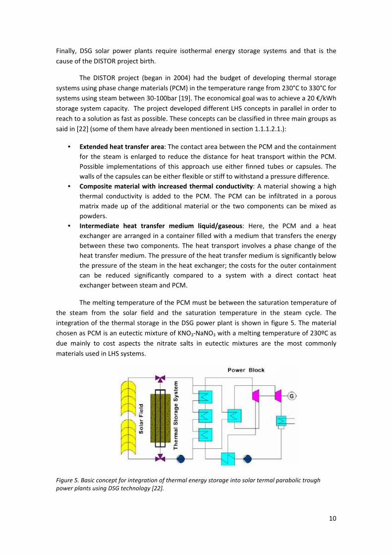
Finally, DSG solar power plants require isothermal energy storage systems and that is the
cause of the DISTOR project birth.
The DISTOR project (began in 2004) had the budget of developing thermal storage
systems using phase change materials (PCM) in the temperature range from 230°C to 330°C for
systems using steam between 30-100bar [19]. The economical goal was to achieve a 20 €/kWh
storage system capacity. The project developed different LHS concepts in parallel in order to
reach to a solution as fast as possible. These concepts can be classified in three main groups as
said in [22] (some of them have already been mentioned in section 1.1.1.2.1.):
• Extended heat transfer area: The contact area between the PCM and the containment
for the steam is enlarged to reduce the distance for heat transport within the PCM.
Possible implementations of this approach use either finned tubes or capsules. The
walls of the capsules can be either flexible or stiff to withstand a pressure difference.
• Composite material with increased thermal conductivity: A material showing a high
thermal conductivity is added to the PCM. The PCM can be infiltrated in a porous
matrix made up of the additional material or the two components can be mixed as
powders.
• Intermediate heat transfer medium liquid/gaseous: Here, the PCM and a heat
exchanger are arranged in a container filled with a medium that transfers the energy
between these two components. The heat transport involves a phase change of the
heat transfer medium. The pressure of the heat transfer medium is significantly below
the pressure of the steam in the heat exchanger; the costs for the outer containment
can be reduced significantly compared to a system with a direct contact heat
exchanger between steam and PCM.
The melting temperature of the PCM must be between the saturation temperature of
the steam from the solar field and the saturation temperature in the steam cycle. The
integration of the thermal storage in the DSG power plant is shown in figure 5. The material
chosen as PCM is an eutectic mixture of KNO3-NaNO3 with a melting temperature of 230ºC as
due mainly to cost aspects the nitrate salts in eutectic mixtures are the most commonly
materials used in LHS systems.
Figure 5. Basic concept for integration of thermal energy storage into solar termal parabolic trough
power plants using DSG technology [22].

11
Figure 6. Schematic of the
sandwich concept using
graphite foil [22].
The extended heat transfer area concept includes two
different approaches. On the one hand the sandwich concept
based on the integration of materials with high thermal
conductivity. Thins plates orthogonal to the axis of the steam
pipes are used. The first materials contemplated as high thermal
conductivity ones were graphite, stainless steel and carbon steel.
Due to the costs and good corrosion resistivity graphite foils are
chosen instead of steel. The final structure can be observed in
figure 6. More details about distances, positions and assembly
can be found in [22].
On the other hand the DISTOR project has deepened in
the macro-encapsulation concept. The PCM is packed into
capsules to reduce the maximum distance for heat transport.
Then the capsules are introduced in a vessel where the
steam/water circulates. As the PCM undergoes a change of
volume of about 10% in the phase change there are two possible
options: using a flexible capsule and filling it completely with PCM
or using a stiff capsule filling it with PCM and gas.
The flexible capsules for high temperature LHS systems is not a feasible option as the
cost of the material needed for the capsules is too high.
For the stiff capsules a cylindrical shape was chosen and the pressure inside the
capsule depending on the amount of PCM was studied. There is the need of less than 80%
PCM volume in order to avoid a serious cyclic load. The capsules can be observed in figure 7.
In the case of the second group, composite material with increased thermal
conductivity, the approach performed is the assembly by compression of a powder mixture of
eutectic NaNO3 /KNO3 and expanded graphite. The result can be observed in figure 8. The
Figure 7. Capsules filled with NaNO3 –
KNO3 used for laboratory scale test [22].
Figure 8. Single segment made of
PCM/composite material used for the
laboratory-scale storage test unit. Holes
are intended for steam pipes [22].

12
content of graphite must be limited as far as it is possible in order to achieve a cost-
effectiveness composite material.
Finally, there is not information available of the third group as it needed more research
and trials than the other two groups. More detailed information about the different
approaches can be found in [22].
The sandwich concept was chosen as the best option and in 2007 a test module of 200
kWh thermal capacity storage system was installed in the Plataforma Solar de Almería (PSA)
where the DISS Project took place. The storage model and the acquisition devices in order to
study its behavior can be observed in figure 9.
Figure 9. General view of the storage module and the system installed in the PSA DISS plant for its
evaluation [23].
More information about the installation can be found in [23] but it is interesting to
remark the design parameters of the test module:
• pressure /nominal temperature: 25 bar/220ºC
• nominal water/steam flow rate: 0,083 kg/s
and the final conclusions of the annual report 2007 [23] concerning the DISTOR project: the
technical feasibility of the molten salt thermal storage concept and later heat recovery by
crystallization was demonstrated during testing. It was also demonstrated how important
tube bundle design is to ensure heat transfer during charging and discharging. The lower
velocity of the working fluid (water) during discharging requires the tube bundles to be sized
for the right convective heat transfer coefficient without excessive pressure drops in the tube
bundle during charging, when the working fluid (steam) density is lower.

13
Although the project was programmed to end in 2007, due to a delay in the
construction the project ended in 2008. It must be mentioned that tests were stopped because
there was a leak in the tube bundle and the cause of the leak was detected. It gave valuable
information for future prototypes. DLR and CIEMAT which were some of the organisms
working in the DISTOR project decided to perform a new LHS test module in PSA out of the
DISTOR Project. This new test module is designed to work for a maximum of 80 bar and 300 ºC
and the salt used is still a nitrate salt. The tests should have been done during 2010 but there is
not available information about it [24].
Within the framework of DISTOR project there are some articles which must be
mentioned. The first article of interest is [25]. A model of a PCM composite block (figure 10)
for heat storage is developed and some simulations and analysis are performed. The use of
blocks allows to adjust the heat storage capacity to the working conditions of the DSG solar
power plant.
Figure 10. Composite block of composite EG-PCM studied in [25].
The PCM composite consists of compressed naturally expanded porous graphite matrix
(CEG). The manufacture was performed by pouring the expanded graphite powder into a cubic
mold of aluminium and then pressed to obtain the porous graphite matix with the desired bulk
apparent density. Then the CEG graphite pores were filled with the binary eutectic
KNO3/NaNO3 mentioned before. Three different composites were obtained varying the
percentage by mass of CEG (3’96, 5’27 and 7’35%) and the thermophysical properties of the
resulting composite materials were studied and are shown in table 2. As it can be observed the
thermal conductivity in the axial direction is lower thant the one in the radial direction due to
the axial compression which is used in the manufacturating method.

14
Material Pure
salt
CEG–salt
composite
(3.96%
mass graphite)
CEG–salt
composite
(5.27%
mass graphite)
CEG–salt
composite
(7.35%
mass graphite)
Axial thermal
conductivity (W/m K)
0,8 1,6 2,6 2,8
Radial thermal
conductivity (W/m K)
0,8 4,1 5,65 8,2
Apparent latent heat
of fusion (J/kg)
94250 90500 89300 87300
Apparent density of
CEG (kg/m3)
- 75 100 140
Table 2. Measured thermophysical properties of the different composites [25]
The detailed heat transfer and fluid flow model is detailed in section 3 from [25] but
due to its complexity as there is the need to know or fix a great amount of parameters a
simplified model is developed in section 4 in order to have an easy and feasible preliminar
design. The simplified model is validated through the comparison with the detailed model.
A design procedure for sizing the storage system is presented. The maximum energy
storage capacity and average power of system are the most important design criteria and
these two parameters are function of the length of the tubes, the number of tubes and the
time of charging the system as can be observed in equation 11 from [25]. There is a design
procedure explained which is based on fixing the internal tube diameter and solving some of
the equations given in [25].
Finally this design procedure is used to design a thermal storage system of 20 kWh
with an average power of 10 kW in order to test the different composites. The detailed
information of the design is shown in table 2 from [25]. It is interesting to remark the
conclusions which are reached. With less than 4% graphite by mass there is a reduction of the
overall length of tubes of 74% with an increase in the PCM composite material weight less than
4,5% and a small decrease in the overall heat storage capacity. This is an important point to
consider as the steel tubes represent a large part in the total cost of the storage system.
The second article within the framework of the DISTOR project which is interesting to
summarize deals with an analysis of a 100 kWth latent heat storage system for DSG using the
sandwich concept presented above. The prototype, which is shown in figure 11, was installed
in PSA and it proved the feasibility of this latent heat storage system.

15
Figure 11 . Sketch of the TES prototype with its dimensions (mm) [26]
The PCM used was an eutectic mixture of 54% wt KNO3/46% NaNO3 and the
conductive fins were 490x490 mm2 and 1 mm thick of expanded graphite. More details about
the prototype dimensions and configuration are shown in table 2 from [26]. It is interesting to
mention the working conditions: a mass flow of 0,08 kg/s, saturated steam at about 235 ºC in
charge mode and saturated water at about 200 ºC in discharge mode.
Different termocouples were placed in 6 different transversal sections in order to
study the behavior of the PCM. The working temperature ranges of the PCM were divided in 4
regions which are specified in [26] both for charge and discharge processes. There were
presented also some calculations which are compared to the experimental results in section
4.1 from [26].
There was a mismatch between the experimental and calculation results in some of
the regions both for charge and discharge processes. One cause is the different steam
production in the central pipes than in the outer pipes. The other cause of the mismatch is an
excess of PCM which had no EG foils and then could not transfer heat in an efficient way. This
must be corrected in other designs taking care of the TES module volume and tube
bundle/PCM arrangement.
There is another disagreement between the theoretical calculations and the
experimental results between the energy which can be charged if there is enough time (58
kWthh) and the energy which can be recovered (40 kWthh). One of the causes is the excess of
mass already commented which does not give any energy in discharge process.
The last simulation performed is the application of the quasi static approximation
which is presented in detail in [26]. This approximation is based on neglecting the sensible heat
exchanged and then the energy equation becomes independent of time. The results of the
16
calculations of the steam quality shown in [26] lead to the following conclusion: at the
beginning of the heat transfer region considered the real HTF condensation is lower than
expected from calculations. Some reasons as told in [26] could be the following:
• Not all tubes condense the same amount of vapor.
• Condensation does not occur along the whole tube length.
• The quasi static approximation cannot be applied at the beginning of charging. In other
words, it is not possible to neglect the sensible heat exchange at the beginning of
charging.
During discharge mode the calculation curve of the steam quality fits the experimental
results if it is considered a minor tube length than the real one taking into account that the
vaporization does not take place in all the tube length due to a deficient thermal insulation.
Finally it is interesting to include the final suggestions of [26] in order to consider them
in future designs:
• PCM mass should not exceed the amount that can be homogeneously melted/frozen
by the tube bundle.
• Thermal insulation to environment is crucial and has to be ensured around the whole
prototype.
• For a detailed description of TES module with sandwich configuration, it is necessary to
improve the quasi static model by introducing a sensible heat term at both beginning
and end of latent heat exchange regions.
1.1.3.2. Active indirect systems
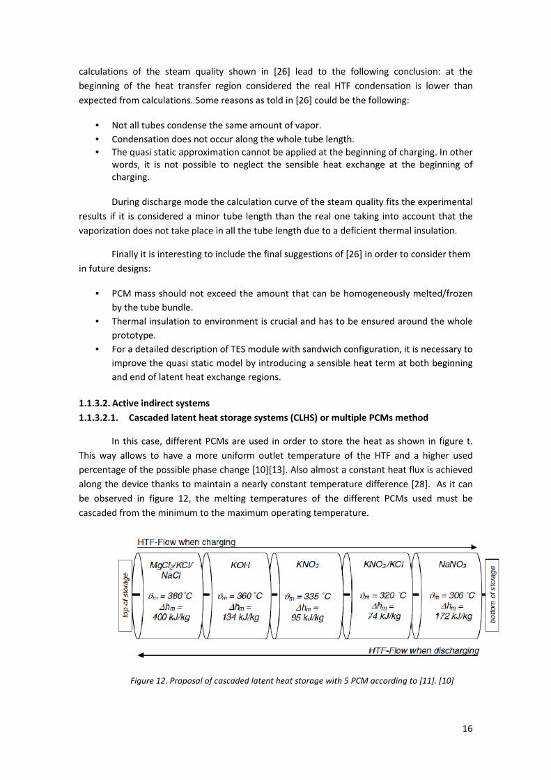
1.1.3.2.1. Cascaded latent heat storage systems (CLHS) or multiple PCMs method
In this case, different PCMs are used in order to store the heat as shown in figure t.
This way allows to have a more uniform outlet temperature of the HTF and a higher used
percentage of the possible phase change [10][13]. Also almost a constant heat flux is achieved
along the device thanks to maintain a nearly constant temperature difference [28]. As it can
be observed in figure 12, the melting temperatures of the different PCMs used must be
cascaded from the minimum to the maximum operating temperature.
Figure 12. Proposal of cascaded latent heat storage with 5 PCM according to [11]. [10]
17
The study performed in [10] is summarized in this section. It is a cascaded latent heat
storage system oriented to be used in a parabolic trough solar power plant with a HTF which
works between 290 and 350 ºC. The materials selected where: sodium nitrate (NaNO3), an
eutectic mixture of potassium nitrate and potassium chloride (KNO3/KCl) and potassium nitrate
(KNO3). The selection of this materials where based on experimental and literature data. The
properties of these three materials, as given in [10] are shown in table 3.
Property Unit NaNO3 KNO3/KCl
95,5/4,5
KNO3
Tm ºC 306 320 335
����hf kJ/kg 172 74 95
ρs kg/m3
2261 2100 2109
Cp,s kJ/kg·K 1,10 1,21 0,953
ks W/m·K 0,5 0,5 0,5
Table 3. Properties of the materials selected in [10].
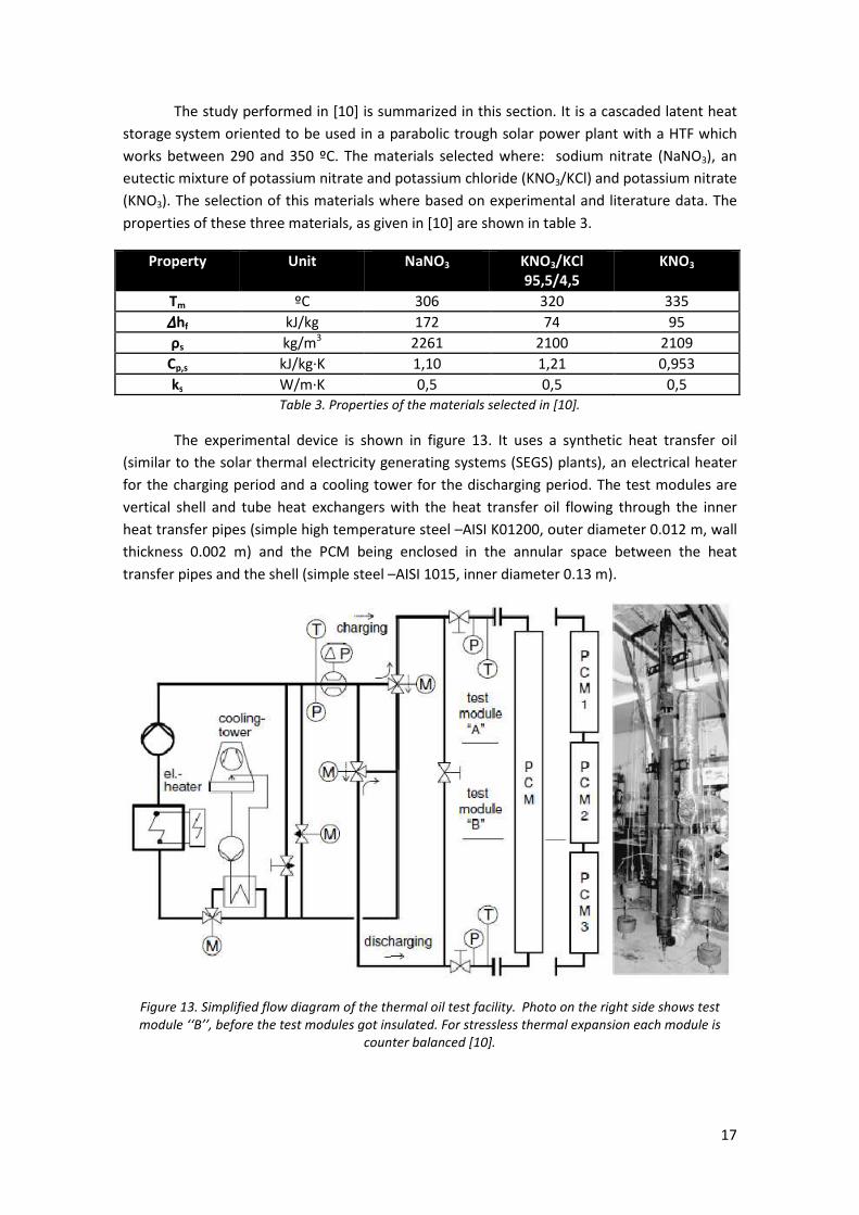
The experimental device is shown in figure 13. It uses a synthetic heat transfer oil
(similar to the solar thermal electricity generating systems (SEGS) plants), an electrical heater
for the charging period and a cooling tower for the discharging period. The test modules are
vertical shell and tube heat exchangers with the heat transfer oil flowing through the inner
heat transfer pipes (simple high temperature steel –AISI K01200, outer diameter 0.012 m, wall
thickness 0.002 m) and the PCM being enclosed in the annular space between the heat
transfer pipes and the shell (simple steel –AISI 1015, inner diameter 0.13 m).
Figure 13. Simplified flow diagram of the thermal oil test facility. Photo on the right side shows test
module ‘‘B’’, before the test modules got insulated. For stressless thermal expansion each module is
counter balanced [10].
18
Due to the PCMs volume change during melting and solidifying the hot oil enters the
test module at the top during charging and the somewhat colder oil enters the test module at
the bottom during discharging. To determine the heat transfer coefficient during melting a
simple double tube test module with a height of 2.5 m was used (Figure 5A). To investigate the
behavior of a CLHS three identical test modules with a height of 1.1 m each where placed
directly above each other to avoid heat losses of the oil when flowing from one test module to
the other (Figure 5B).
Temperature sensors were placed inside the heat transfer pipes to measure the oil’s
temperature at the inlet, during the way through the test module and at the outlet. Further
temperature sensors were placed in the annular gap around the heat transfer pipes to
measure the PCMs temperature.
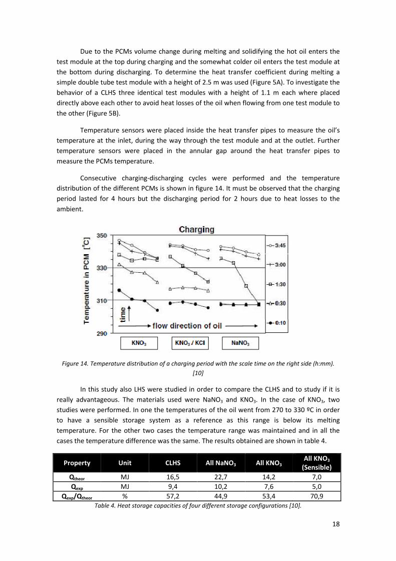
Consecutive charging-discharging cycles were performed and the temperature
distribution of the different PCMs is shown in figure 14. It must be observed that the charging
period lasted for 4 hours but the discharging period for 2 hours due to heat losses to the
ambient.
Figure 14. Temperature distribution of a charging period with the scale time on the right side (h:mm).
[10]
In this study also LHS were studied in order to compare the CLHS and to study if it is
really advantageous. The materials used were NaNO3 and KNO3. In the case of KNO3, two
studies were performed. In one the temperatures of the oil went from 270 to 330 ºC in order
to have a sensible storage system as a reference as this range is below its melting
temperature. For the other two cases the temperature range was maintained and in all the
cases the temperature difference was the same. The results obtained are shown in table 4.
Property Unit CLHS All NaNO3 All KNO3 All KNO3
(Sensible)
Qtheor MJ 16,5 22,7 14,2 7,0
Qexp MJ 9,4 10,2 7,6 5,0
Qexp/Qtheor % 57,2 44,9 53,4 70,9
Table 4. Heat storage capacities of four different storage configurations [10].

19
Qtheor indicates the theoretical storage capacity of each configuration which is
calculated using equation 2. Qexp shows the experimental results and the third line is the ratio
between these last two values. The interesting points to comment are on the one hand the
higher storage capacity of the LHS systems in front the sensible storage system, the higher
storage capacity of the All NaNO3 sample due to its high heat of fusion and the higher ratio
Qexp/Qtheor of the CLHS in front the other LHS systems which was one of the advantages of this
type of system commented at the beginning of the section.
������ = � ���� · (� ��, �
�!
"#$
%#&· �� + ∆ℎ� + � ��,(
�)*
�· ��
Equation 2. Theoretical storage capacity of a latent heat storage system.
A simulation with Dymola-Modelica was also accomplished in order to compare the
experimental data. More details about the model can be found in [10] but it must be remarked
that all simulation results matched the experimental data well.
The model verified was used to design a CLHS for a 50 MWel parabolic trough power
plant with a storage capacity of 875 MWhth to realize a discharging duration of 6 h (split into
two storages with 3h each for more flexibility) while charged for 2*4 h. The storage operation
boundary conditions were:
• Charging: Toil, top = 391 ºC and Toil, bottom = 290 - 330 ºC
• Discharging: Toil, bottom =285 ºC and Toil, out =390 - 350 ºC
and the PCMs configuration was like the one shown in figure 4.
More details about the design and simulation are included in [10]. In this case also the
study of LHS systems using one PCM was carried out due to comparison reasons and it is
interesting to plot the results obtained (table 5 and figure 15).
Property Unit CLHS All NaNO3 All KNO3 All
MgCl2/KCl/NaCl
Qsim MJ 64,5 74,0 67,7 56,0
mphasechange/mtotal % 47 8 30 4
Table 5. Simulated storage capacities and mass portions to undergo a phase change between charging
and discharging.[10]
20
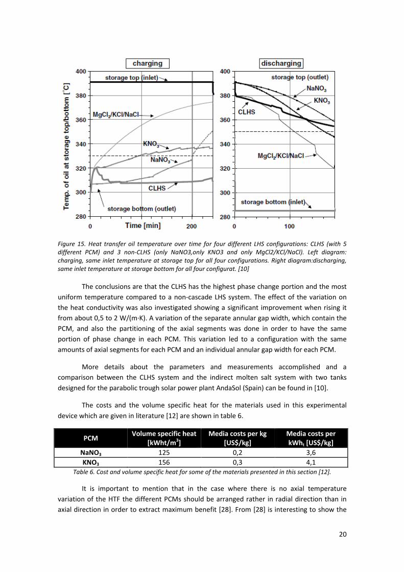
Figure 15. Heat transfer oil temperature over time for four different LHS configurations: CLHS (with 5
different PCM) and 3 non-CLHS (only NaNO3,only KNO3 and only MgCl2/KCl/NaCl). Left diagram:
charging, same inlet temperature at storage top for all four configurations. Right diagram:discharging,
same inlet temperature at storage bottom for all four configurat. [10]
The conclusions are that the CLHS has the highest phase change portion and the most
uniform temperature compared to a non-cascade LHS system. The effect of the variation on
the heat conductivity was also investigated showing a significant improvement when rising it
from about 0,5 to 2 W/(m·K). A variation of the separate annular gap width, which contain the
PCM, and also the partitioning of the axial segments was done in order to have the same
portion of phase change in each PCM. This variation led to a configuration with the same
amounts of axial segments for each PCM and an individual annular gap width for each PCM.
More details about the parameters and measurements accomplished and a
comparison between the CLHS system and the indirect molten salt system with two tanks
designed for the parabolic trough solar power plant AndaSol (Spain) can be found in [10].
The costs and the volume specific heat for the materials used in this experimental
device which are given in literature [12] are shown in table 6.
PCM Volume specific heat
[kWht/m3]
Media costs per kg
[US$/kg]
Media costs per
kWht [US$/kg]
NaNO3 125 0,2 3,6
KNO3 156 0,3 4,1
Table 6. Cost and volume specific heat for some of the materials presented in this section [12].
It is important to mention that in the case where there is no axial temperature
variation of the HTF the different PCMs should be arranged rather in radial direction than in
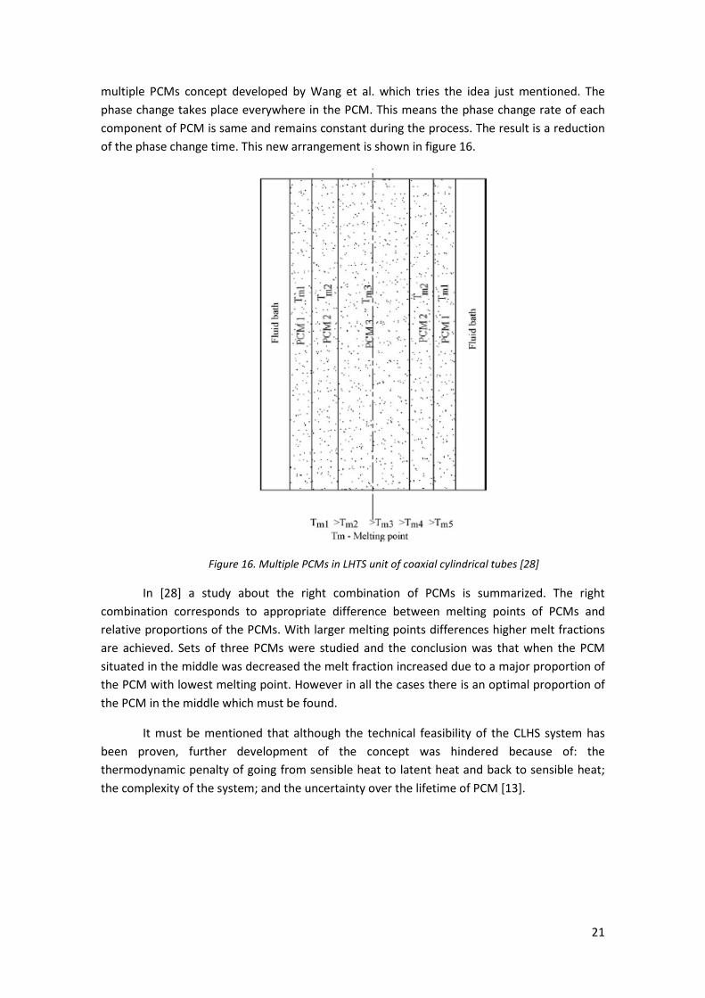
axial direction in order to extract maximum benefit [28]. From [28] is interesting to show the
21
multiple PCMs concept developed by Wang et al. which tries the idea just mentioned. The
phase change takes place everywhere in the PCM. This means the phase change rate of each
component of PCM is same and remains constant during the process. The result is a reduction
of the phase change time. This new arrangement is shown in figure 16.
Figure 16. Multiple PCMs in LHTS unit of coaxial cylindrical tubes [28]
In [28] a study about the right combination of PCMs is summarized. The right
combination corresponds to appropriate difference between melting points of PCMs and
relative proportions of the PCMs. With larger melting points differences higher melt fractions
are achieved. Sets of three PCMs were studied and the conclusion was that when the PCM
situated in the middle was decreased the melt fraction increased due to a major proportion of
the PCM with lowest melting point. However in all the cases there is an optimal proportion of
the PCM in the middle which must be found.
It must be mentioned that although the technical feasibility of the CLHS system has
been proven, further development of the concept was hindered because of: the
thermodynamic penalty of going from sensible heat to latent heat and back to sensible heat;
the complexity of the system; and the uncertainty over the lifetime of PCM [13].

22
1.1.3.2.2. PCM-based TES for Concentrated Solar Power Tower
As there is the need to store energy in different solar applications: power tower,
trough, linear Fresnel collectors… there is the need to develop new technologies in order to
reduce the volume and the costs. Terrafore which is a consulting and technology development
firm is working on the topic.
The project is called Heat Transfer and Latent Heat Storage in Inorganic Molten Salts
for Concentrating Solar Power Plants. It started on March 2009 and it is programmed to end on
December 2011. The concept which is being developed is shown in figure 17. It works with the
thermocline concept presented in the previous section.
Figure 17. PCM-based TES design being developed by Terrafore [16]
The salt is heated up and inserted on the top of the tank. Then the hot fluid is on the
top and the cold fluid at the bottom and when the tank is completely charged all the salt is at
the same temperature. For discharging, the salt on the top circulates to the HX-2 in figure 17
(heat exchanger) to generate superheated steam and then reaches a boiler (also a heat
exchanger) where the feed water is vaporized resulting in saturated steam. The salt coming
out from the boiler is around 40% solid forming a slurry with the liquid phase which is
introduced at the bottom of the tank having the solid at the bottom and the liquid on the top.
As the thermocline concept is used, one of the tasks of the project has been the
development of an active thermal stratification management controller required for PCM
storage and it has been demonstrated that this controller can be applied to any thermocline
storage
As it is said in [17] the objective of the project is to develop and demonstrate a shell
and coated tube heat exchanger that significantly improves heat transfer from a freezing salt
23
mixture as the heat transfer rate is one of the challenges of the LHS systems. The salt melting
temperatures studied go from 275 to 350 ºC and the operating temperatures to 570 ºC.
There were over 700 salt mixtures examined but very few met selection criteria and
the salt chosen for the rest of the project is a nitrate based mixture.
The major challenge in the project as told in [16] is that when the salt solidifies on heat
exchanger surfaces, the heat transfer rates decreases significantly requiring large heat
exchangers. In order to solve this problem, the approach proposed by Terrafore is based on
three elements: choosing a dilute composition of salt mixtures that form a eutectic with a
specific phase diagram called simple phase diagram, using an additive(s) that will cause the salt
to solidify as a slush and that can be easily washed off the heat transfer surface and using a
coating on the heat exchanger tubes that discourages strong adhesion of freezing salt [16].
Two coatings have been selected in the first phase of the project in order to perform
more tests in the next phases.
There is not more information about the following phases of the project but as the
schedule in [17] shows, the next tasks should have been already completed:
• Build a scaled model experiment by July 2010
• Conduct tests with coated tube heat exchangers between July and December 2010
• Quantify adhesion properties of coatings before August 2010
• Characterize salt morphology near and during freezing by October 2010
• Complete modeling and system analysis with PCM TES and Power Tower CSP by
November 2010
1.1.3.3. Passive systems
1.1.3.3.1. Combination of sensible and latent storage
In [14] a three-part storage system for a direct steam generation device is proposed
using concrete and PCM as it is shown in figure 18. In this concrete studied case the total
storage capacity is about 1 MWh. The concrete storage modules are used for preheating and
superheating the steam and the PCM storage module is used to evaporate/condensate the
heat transfer fluid (water). This last heat transfer represents the 70% of the required energy.

24
Figure 18. Overview of a three-part thermal energy storage system for DSG combining sensible and
latent heat storage [14]
During discharging, feed water enters the preheater (A) and is heated up close to the
boiling curve (B), then the water is circulated through the PCM storage, where part of the
water evaporates (C). The steam is separated from the water in the steam drum and is
superheated in the concrete unit (D), while the remaining water is recirculated through the
PCM storage [14].
In the latent storage module the material chosen as PCM was sodium nitrate (NaNO3)
by the sandwich concept using aluminum fins which is detailed in [15]. Its melting temperature
is 306 ºC.
Prior to the large scale demonstration PCM storage module, a lab-scale test module
with 140 kg NaNO3 and the sandwich concept for enhancement of heat transfer was
successfully tested for more than 4000 h and the tests comprised 172 melting / solidification
cycles. A very high level of specific capacity and specific power was achieved, so it was
demonstrated that these PCM units are a viable option for steam storage systems [14].
Once the lab-scale was proved, the design was scaled up to about 14 tons of salt with a
latent heat capacity of approx. 680 kWh and adapted to the design parameters of the
water/steam test loop (128 bar, 400 °C). The tube register is arranged vertically because the
sodium nitrate experiences a volume increase of approx. 10 % during melting. Then an excess
volume is provided for the liquid phase at the top of the storage to guarantee the good
performance of the module. The module already constructed is shown in figure 19 and
detailed information about the construction of the module is presented also in [14]
In charging mode, steam with a temperature slightly above saturation properties
(typically about 107 bar and 320 °C) is routed into the PCM module where it condenses. The
flow direction during charging is from top to bottom so that the condensate is removed by
gravity. A condensate drain assures that the medium leaves the module only in liquid form.
The module is expected to be able to condense the full mass flow of 0.8 kg/s that the test loop
can provide. [14]
25
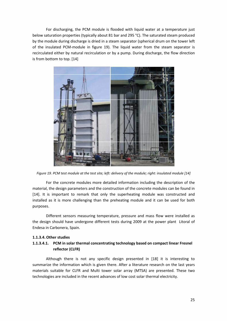
For discharging, the PCM module is flooded with liquid water at a temperature just
below saturation properties (typically about 81 bar and 295 °C). The saturated steam produced
by the module during discharge is dried in a steam separator (spherical drum on the tower left
of the insulated PCM-module in figure 19). The liquid water from the steam separator is
recirculated either by natural recirculation or by a pump. During discharge, the flow direction
is from bottom to top. [14]
Figure 19. PCM test module at the test site; left: delivery of the module; right: insulated module [14]
For the concrete modules more detailed information including the description of the
material, the design parameters and the construction of the concrete modules can be found in
[14]. It is important to remark that only the superheating module was constructed and
installed as it is more challenging than the preheating module and it can be used for both
purposes.
Different sensors measuring temperature, pressure and mass flow were installed as
the design should have undergone different tests during 2009 at the power plant Litoral of
Endesa in Carbonera, Spain.
1.1.3.4. Other studies
1.1.3.4.1. PCM in solar thermal concentrating technology based on compact linear Fresnel
reflector (CLFR)
Although there is not any specific design presented in [18] it is interesting to
summarize the information which is given there. After a literature research on the last years
materials suitable for CLFR and Multi tower solar array (MTSA) are presented. These two
technologies are included in the recent advances of low cost solar thermal electricity.
26
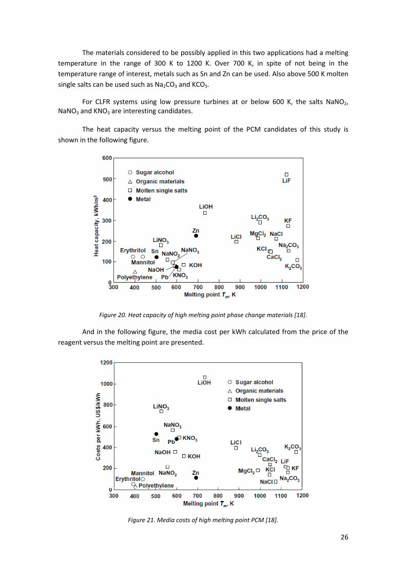
The materials considered to be possibly applied in this two applications had a melting
temperature in the range of 300 K to 1200 K. Over 700 K, in spite of not being in the
temperature range of interest, metals such as Sn and Zn can be used. Also above 500 K molten
single salts can be used such as Na2CO3 and KCO3.
For CLFR systems using low pressure turbines at or below 600 K, the salts NaNO2,
NaNO3 and KNO3 are interesting candidates.
The heat capacity versus the melting point of the PCM candidates of this study is
shown in the following figure.
Figure 20. Heat capacity of high melting point phase change materials [18].
And in the following figure, the media cost per kWh calculated from the price of the
reagent versus the melting point are presented.
Figure 21. Media costs of high melting point PCM [18].
27
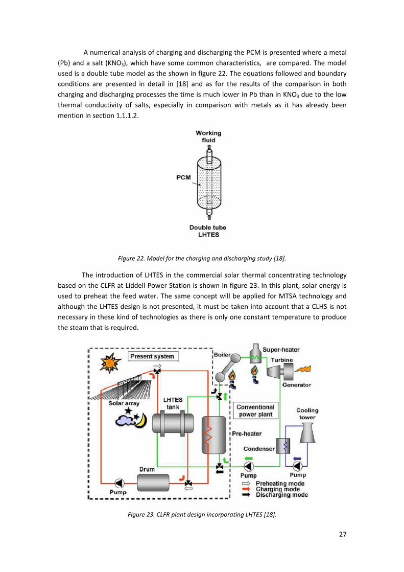
A numerical analysis of charging and discharging the PCM is presented where a metal
(Pb) and a salt (KNO3), which have some common characteristics, are compared. The model
used is a double tube model as the shown in figure 22. The equations followed and boundary
conditions are presented in detail in [18] and as for the results of the comparison in both
charging and discharging processes the time is much lower in Pb than in KNO3 due to the low
thermal conductivity of salts, especially in comparison with metals as it has already been
mention in section 1.1.1.2.
Figure 22. Model for the charging and discharging study [18].
The introduction of LHTES in the commercial solar thermal concentrating technology
based on the CLFR at Liddell Power Station is shown in figure 23. In this plant, solar energy is
used to preheat the feed water. The same concept will be applied for MTSA technology and
although the LHTES design is not presented, it must be taken into account that a CLHS is not
necessary in these kind of technologies as there is only one constant temperature to produce
the steam that is required.
Figure 23. CLFR plant design incorporating LHTES [18].
28
1.1.3.4.2 Reflux heat transfer storage (RHTS)
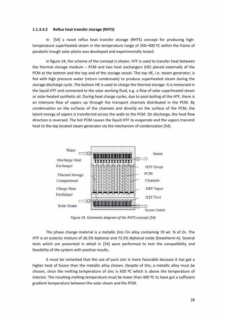
In [54] a novel reflux heat transfer storage (RHTS) concept for producing high-
temperature superheated steam in the temperature range of 350–400 ºC within the frame of
parabolic trough solar plants was developed and experimentally tested.
In figure 24, the scheme of the concept is shown. HTF is used to transfer heat between
the thermal storage medium – PCM and two heat exchangers (HE) placed externally of the
PCM at the bottom and the top and of the storage vessel. The top HE, i.e. steam generator, is
fed with high pressure water (return condensate) to produce superheated steam during the
storage discharge cycle. The bottom HE is used to charge the thermal storage. It is immersed in
the liquid HTF and connected to the solar working fluid, e.g. a flow of solar superheated steam
or solar-heated synthetic oil. During heat charge cycles, due to pool-boiling of the HTF, there is
an intensive flow of vapors up through the transport channels distributed in the PCM. By
condensation on the surfaces of the channels and directly on the surface of the PCM, the
latent energy of vapors is transferred across the walls to the PCM. On discharge, the heat flow
direction is reversed. The hot PCM causes the liquid HTF to evaporate and the vapors transmit
heat to the top located steam generator via the mechanism of condensation [54].
Figure 24. Schematic diagram of the RHTS concept [54].
The phase change material is a metallic Zinc-Tin alloy containing 70 wt. % of Zn. The
HTF is an eutectic mixture of 26.5% biphenyl and 73.5% diphenyl oxide (Dowtherm-A). Several
tests which are presented in detail in [54] were performed to test the compatibility and
feasibility of the system with positive results.
It must be remarked that the use of pure zinc is more favorable because it has got a
higher heat of fusion than the metallic alloy chosen. Despite of this, a metallic alloy must be
chosen, since the melting temperature of zinc is 420 ºC which is above the temperature of
interest. The resulting melting temperature must be lower than 400 ºC to have got a sufficient
gradient temperature between the solar steam and the PCM.

29
In order to extent the operating time of solar thermal electric systems a thermal buffer
(also with the RHTS concept) is added to the system arranged in series to the main one. This
buffer serves to settle the time-variable temperature of steam after the main storage caused
by the gradually solidification of the alloy (non-isothermal).
Additionally two different options for installing the thermal storage system are
studied: serial connection (using the prime solar system) and parallel connection (using a
supplementary solar system). The parallel connection offers a larger thermal capacity but
there is an extra investment in the supplementary solar system.
Finally, although the PCM chosen is more expensive than the salts used in other latent
heat storage systems, the conclusion is that there are several advantages which can lead to the
success of this concept in front of other ones:
• Outstanding chemical stability of the tested Zn70Sn30 – HTF system.
• High substance density and superior thermal conductivity of Zn70Sn30, roughly 50
W/m-K in liquid state that is about two orders of magnitude over molten salts.
• High heat transfer quality demonstrated in the experiments that can be compared to
the utility of thermosyphons [54].
1.1.4. Conductivity enhancement
As the conductivity enhancement of PCM is one of the most difficult challenges as it
has already been mentioned it is interesting to dedicate one section to this topic. As it has
been said in the DISTOR project section there are two main approaches to achieve the budget
of improving the thermal conduction (although there were considered three approaches the
studies performed are mainly focused in two). On the one hand it is possible to increase the
heat transfer area and on the other hand it is possible to use PCM composites. In the first case
and for high temperature application there are two options: the macro-encapsulation and the
use of a tubular heat exchanger with finned tubes (what is known as sandwich concept). In the
following sections some studies about the conductivity enhancement are presented.
1.1.4.1. Sandwich concept
In reference [27] and as it has already been mentioned in the DISTOR Project graphite
foil, stainless steel, carbon steel and aluminum are considered as possible materials in order to
construct the fins. Although in a preliminary thought stainless steel would be the chosen one
due to its compatibility with the steel tubes of the heat exchangers, graphite foil or aluminum
are the chosen ones. The reason is their more favorable heat conductivity which allows a less
volume of the material to be used.
As told in [27] the application of fins made of expanded graphite offers several
advantages besides good thermal conductivity. Expanded graphite shows good chemical
stability in nitrates and nitrites at temperatures up to 250 °C and galvanic corrosion does not
occur in contact with steel tubes. Since graphite foils, often used as sealing material, show a
high flexibility, a close contact between tubes and fins can easily be realized.

30
Aluminum fins are applicable for temperatures up to 330 °C. The mounting of the fins
on the tubes is an essential issue for the sandwich concept. Galvanic corrosion of aluminum
with carbon steel and sodium nitrate has been analyzed, showing no critical corrosion. A good
mechanical contact between fins and tubes is important [27].
In the following figure it is possible to observe the improvement which is achieved by
the use of fins and also the better behavior of the graphite foils fins in front of the steel ones.
Figure 25. Comparison of charge state for PCM without fins, with steel fins of different thickness and
with graphite fins [27].
In [27] another study of the sandwich concept is given. Based
on previous experiments which are summarized in table 3 from [27],
an experimental demonstration is performed with the aim of
optimizing the thermo-economic graphite-based sandwich concept. A
storage module using sodium nitrate (NaNO3) as PCM and aluminum
for fins is chosen due to incompatibility between graphite and NaNO3
in the working temperature range. It is shown in figure 26 and the fins
can be observed in figure 27.
Figure 26. NaNO3 PCM
Storage Test
Module [27].
Figure 27. Fins for heat transfer enhancement [27]

31
Thanks to some measurements the theoretical capacity of the storage module was
calculated and was of 8,51 kWh. Some cycles (charge and discharge processes) were
performed in order to calculate the real storage capacity. The result was a storage capacity of
7,87 ± 0.03 kWh in the charge mode and of 7,20 ± 0.05 kWh in the discharge mode. More
details about the tests performed are presented in [27]. The difference between the
theoretical and the measured capacity are awarded to uncertainties in the measurement of
the oil temperature but in any case the test results and the expectations are in good
agreement.
The conclusions of this report are the following: High temperature latent heat storage
with high capacity factors was demonstrated at different temperature levels. The sandwich
concept using fins made either from graphite or aluminum was proven as the best option to
realize cost-effective latent heat energy storage. The application of graphite is preferred for
applications up to 250 °C; at higher temperatures aluminum fins are used [27].
1.1.4.2. PCM composite
1.1.4.2.1. Graphite
The thermal conductivity of graphite varies from 24 to 470 W/m·K. The thermal
conductivity of PCM(0.2–1 W/m K) can be intensified by a factor of 5–100 depending upon the
density of graphite added into the PCM. Cabeza et al. have found that using PCM-graphite
compound is the best option in applications like thermally stratified storage tank. The cheapest
form of graphite is natural graphite flakes, which are composed of dense staked graphite
layers. However, it is found that expanded graphite (EG) can be a better choice as it is of better
absorbability due to high porosity. When the EG is mixed with PCM, the melted PCM will be
absorbed in the pores of the EG results in composite PCM. The thermal conductivity and
thermal capacity of the composite PCM depend upon the relative proportion of graphite and
PCM [28].
An article about the conductivity enhancement by the use of PCM composites using
graphite can be found in [29]. Three different types of industrial graphite were tested: graphite
flakes (NG), expanded natural graphite (ENG) and expanded graphite powder (GFG). Due to
their different properties, the same graphite content in the composite results in different
properties (thermal conductivity, anisotropy…).
The elaboration route which was normally used is the dispersion and it is detailed in
[29]. Four industrial grade composites were studied. They were all composed by the
NaNO3/KNO3 eutectic at industrial grade but different graphite types and contents: the
NG/400/22, the NG/400/30, the GFG/50/20 and the GFG/500/21. To understand the
nomenclature: NG/400/22 is made of 22% wt of NG flakes of 400 mm. Other salts were
considered as PCM in a previous study and are presented in table 1 from [29] but due to
corrosion aspects, hygroscopic behavior, industrial availability and cost and hazard the nitrate
eutectic was selected for further studies.
The properties of the different composites were determined: the melting and
solidification temperatures, the latent heat and the thermal conductivity. The results show

32
that the latent heat of the PCM is not affected by the graphite content but it affects the phase
change transition temperature variation which decreases at increasing graphite amount [29].
The different industrial made composites were thermally cycled 200 times and
characterized. The latent heat is lowered after the 200 cycles and it depends mainly upon the
size of the graphite flakes. A further study of the influence of particle size was performed and
the conclusion was that it only affects for the largest amount of graphite flakes.
With respect to thermal conductivity, the results obtained leaded to the following
conclusions: different graphite sizes and types lead to a significant variation in conductivity, a
larger particle size or a lower density particle (which leads to a larger number of dispersed
particles) are favorable to the creation of a better conductive network within the PCM. The
influence of temperature on thermal conductivity was also studied and it was proved that the
thermal conductivity is strongly temperature dependant [29].
As the thermal conductivity is still low for the solar application (within the framework
of DISTOR project the target is a thermal conductivity of 8 w/m·K) it is proposed to use
additional conductive graphite fins radially distributed in the volume with respect to the heat
transfer tubes. To study the efficiency of this approach a simulation was performed and it is
detailed in [29]. The conclusion of the simulation is that each particular case of application (in
term of geometry and working parameters) will lead to a specific technico-economic optimum
defined by the graphite amount within the composite and the interfoil distance between the
graphite fins.
1.1.4.2.2. Graphite and metal foams
In [30] there is another study of the conductivity enhancement in high temperature
storage systems. The PCM used is NaNO3 (properties have already been shown in table 3) and
there are two improving ways presented: using metal foam or using expanded graphite. An
experimental device which is shown in figure 28 was constructed in order to study the
conductivity enhancement and its advantages in the charge/discharge processes. More details
about the sensors, devices, insulation and container are presented in [30].
Figure 28. Experimental device for the study of the conductivity enhancement [30].
33
Three different charging processes and one discharging process are studied. The
results show that the conductivity enhancement with the two methods is achieved. Porosity
plays an important role and the conclusion is that reducing porosity and cell size significant
conductivity enhancement is accomplished. It must be taken into account that the lower
porosity implies a lower total heat storage capacity.
One of the charging processes studied correspond to the phase change of the PCM
(250 to 350 ºC) and the stages and dominant heat transfers mechanisms during the process
are explained with detail in [30]. It must be mentioned that NaNO3 has a solid-solid phase
change at 276 ºC and this leads to a little step in the temperature curves.
Another point to be remarked is that although metal foam structures enhance
conduction, natural convection can be weakened by metal foams. In the case of expanded
graphite natural convection can be severely suppressed due to its small pore size and higher
viscosity inside the composite [30]. Due to this fact, after the complete melting of the PCM,
temperature curves are much more complex with metal foams or expanded graphite than in
the case of the pure salt. In some of the tested containers this fact leads to a lower heat
transfer in the liquid phase region, namely porous materials do not always enhance heat
transfer in every regime.
For the discharging process it is shown that both methods allow a faster discharging
process thanks to achieving also an enhancement in the heat transfer process.
Besides the charging and discharging studies, a report about the compatibility in terms
of corrosion between NaNO3 and metal foams is also presented. Heavy corrosion effects in the
metal foams can be observed after some tests reducing the positive effect of using metal
foams in the enhancement of thermal conductivity of PCM.
Although the overall performance of metal foams is superior to that of expanded
graphite, graphite has a good chemical stability to resist corrosion as it has been mentioned
before in section 1.1.4.1. The disadvantage of the expanded graphite pointed in [30] is the
difficulty of the composite manufacturing (mixing process) with possible voids inside the
composites with larger fraction of expanded graphite.
Finally a discussion about the economic impact of the use of composites in TES is
presented in [30]. The loss of thermal storage capacity is worth by the enhancement in heat
transfer. It is said in [30] that the overall cost of the TES system using expanded graphite can
be estimated as a little change or even up to 10% reduction thanks to the reduction of the area
of heat exchangers and the relative low cost of the expanded graphite. In respect to the use of
metal foams, as they have a higher price than the expanded graphite, it is estimated a 10-20%
rise on the cost of the TES system [30].
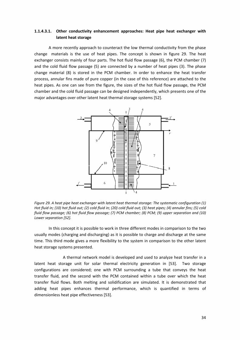
34
1.1.4.3.1. Other conductivity enhancement approaches: Heat pipe heat exchanger with
latent heat storage
A more recently approach to counteract the low thermal conductivity from the phase
change materials is the use of heat pipes. The concept is shown in figure 29. The heat
exchanger consists mainly of four parts. The hot fluid flow passage (6), the PCM chamber (7)
and the cold fluid flow passage (5) are connected by a number of heat pipes (3). The phase
change material (8) is stored in the PCM chamber. In order to enhance the heat transfer
process, annular fins made of pure copper (in the case of this reference) are attached to the
heat pipes. As one can see from the figure, the sizes of the hot fluid flow passage, the PCM
chamber and the cold fluid passage can be designed independently, which presents one of the
major advantages over other latent heat thermal storage systems [52].
Figure 29. A heat pipe heat exchanger with latent heat thermal storage: The systematic configuration (1)
Hot fluid in; (10) hot fluid out; (2) cold fluid in; (20) cold fluid out; (3) heat pipes; (4) annular fins; (5) cold
fluid flow passage; (6) hot fluid flow passage; (7) PCM chamber; (8) PCM; (9) upper separation and (10)
Lower separation [52].
In this concept it is possible to work in three different modes in comparison to the two
usually modes (charging and discharging) as it is possible to charge and discharge at the same
time. This third mode gives a more flexibility to the system in comparison to the other latent
heat storage systems presented.
A thermal network model is developed and used to analyze heat transfer in a
latent heat storage unit for solar thermal electricity generation in [53]. Two storage
configurations are considered; one with PCM surrounding a tube that conveys the heat
transfer fluid, and the second with the PCM contained within a tube over which the heat
transfer fluid flows. Both melting and solidification are simulated. It is demonstrated that
adding heat pipes enhances thermal performance, which is quantified in terms of
dimensionless heat pipe effectiveness [53].

35
Although it has the budget of developing a latent heat storage system for high
temperature applications, the experiments performed used water as a HTF and a paraffin with
a Tm of 52,1 ºC as the PCM. As it is outside the temperature of range of interest, no more
details about the model will be presented. It must be remarked that is a concept which must
be taken into account as possibly further studies will be available during the next years.
1.2. THERMO-CHEMICAL STORAGE
As it has been said in the introduction the chemical storage is the third approach
studied to store heat. This one is the approach which has been developed less. It is based on
using reversible thermo-chemical reactions: chemical compounds store energy by an
endothermic reaction and the energy is then released in the recombination of the compounds
by an exothermic reaction [7].
The most interesting advantage of this method is that the enthalpy of reaction is
considerably larger than the specific heat or the heat of fusion. Then the storage density is
much better. Some of the compounds and reactions with their respective temperatures and
heat of reaction and the storage density are shown in table 4 from [7] and in table 8 from [8].
Another advantage from this approach is that thermal insulation is not required (lower
cost) but on the other hand the chemical compounds must be heated and cooled before
reactions (higher cost).
1.2.1 Properties required
As told in [7] when selecting the chemical compounds, some properties are required in
order to achieve the desired performance:
• Reversibility: The reaction must go to completion; no side reactions or changes in
reaction rate with time should occur.
• Reaction rates: Both forward and reverse reactions must be rapid enough to absorb all
the available energy or release it promptly. The reaction rates must not decrease with
cycling. Such a decrease can be observed, if structural changes of the storage medium
occur (e.g., crushing of particles into powder).
• Controllability: The reactions must be controllable because they have to be turned on
and off when required. Controllability is achieved by product separation, by controlling
the temperature and pressure, or by catalysts.
• Ease of storage: The reaction products have to be easily separable prior to storage.
Reactions must not occur at storage temperature.
• Safety: Toxicity, inflammability, and corrosiveness of the reaction products may pose
unacceptable safety hazards.
• Cost: Cost should be low; this requires materials which are readily available.
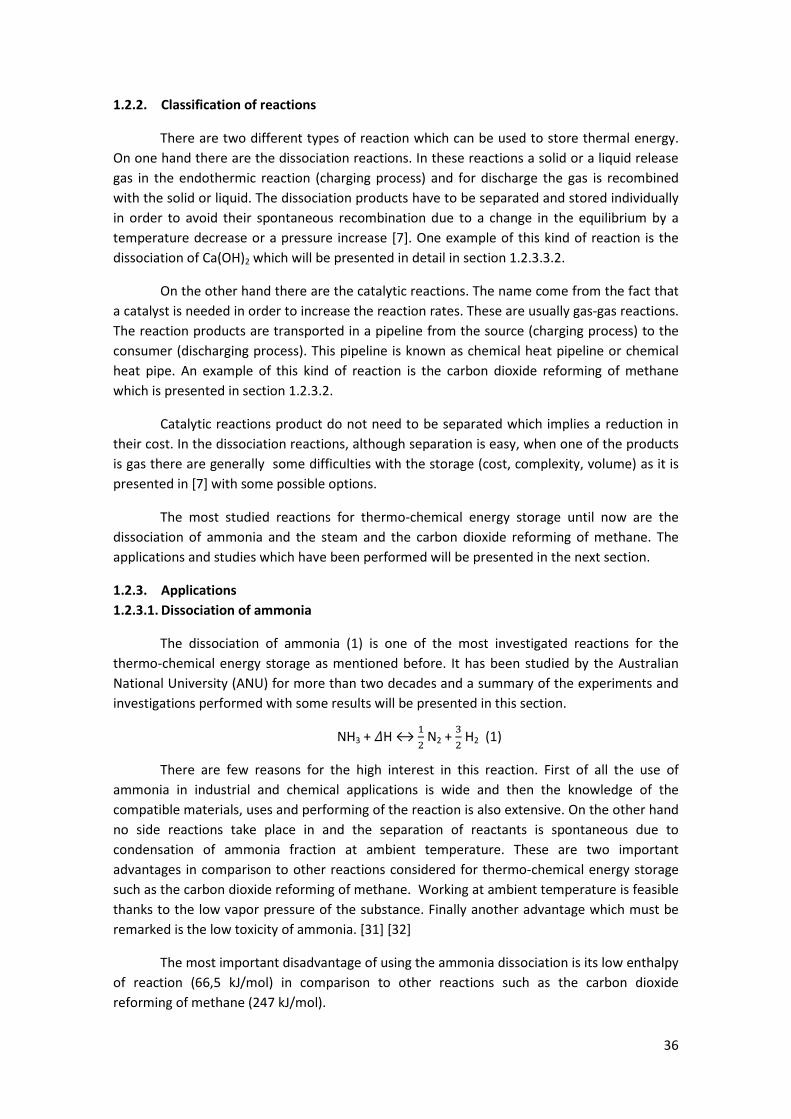
36
1.2.2. Classification of reactions
There are two different types of reaction which can be used to store thermal energy.
On one hand there are the dissociation reactions. In these reactions a solid or a liquid release
gas in the endothermic reaction (charging process) and for discharge the gas is recombined
with the solid or liquid. The dissociation products have to be separated and stored individually
in order to avoid their spontaneous recombination due to a change in the equilibrium by a
temperature decrease or a pressure increase [7]. One example of this kind of reaction is the
dissociation of Ca(OH)2 which will be presented in detail in section 1.2.3.3.2.
On the other hand there are the catalytic reactions. The name come from the fact that
a catalyst is needed in order to increase the reaction rates. These are usually gas-gas reactions.
The reaction products are transported in a pipeline from the source (charging process) to the
consumer (discharging process). This pipeline is known as chemical heat pipeline or chemical
heat pipe. An example of this kind of reaction is the carbon dioxide reforming of methane
which is presented in section 1.2.3.2.
Catalytic reactions product do not need to be separated which implies a reduction in
their cost. In the dissociation reactions, although separation is easy, when one of the products
is gas there are generally some difficulties with the storage (cost, complexity, volume) as it is
presented in [7] with some possible options.
The most studied reactions for thermo-chemical energy storage until now are the
dissociation of ammonia and the steam and the carbon dioxide reforming of methane. The
applications and studies which have been performed will be presented in the next section.
1.2.3. Applications
1.2.3.1. Dissociation of ammonia
The dissociation of ammonia (1) is one of the most investigated reactions for the
thermo-chemical energy storage as mentioned before. It has been studied by the Australian
National University (ANU) for more than two decades and a summary of the experiments and
investigations performed with some results will be presented in this section.
NH3 + �H ↔ &+ N2 +
,+ H2 (1)
There are few reasons for the high interest in this reaction. First of all the use of
ammonia in industrial and chemical applications is wide and then the knowledge of the
compatible materials, uses and performing of the reaction is also extensive. On the other hand
no side reactions take place in and the separation of reactants is spontaneous due to
condensation of ammonia fraction at ambient temperature. These are two important
advantages in comparison to other reactions considered for thermo-chemical energy storage
such as the carbon dioxide reforming of methane. Working at ambient temperature is feasible
thanks to the low vapor pressure of the substance. Finally another advantage which must be
remarked is the low toxicity of ammonia. [31] [32]
The most important disadvantage of using the ammonia dissociation is its low enthalpy
of reaction (66,5 kJ/mol) in comparison to other reactions such as the carbon dioxide
reforming of methane (247 kJ/mol).

37
The recent literature about the ammonia thermo-chemical energy storage is mainly
based on the work performed by ANU and is based on a pseudo-homogenous model adapted
from the work of Richardson et al. (1988) and the model is described in detail by Lovegrove
(1995).
In [33] a study about an endothermic reactor for an ammonia thermo-chemical energy
storage system is presented. The most important points about it is the feasibility of reaching
pressures up to 30 MPa which provides benefits in the heat transfer coefficients and the
volumetric energy storage density. In this technical report also different receiver/reactor
concepts are investigated. The details about the tests and results can be found in [33] but it is
important to remark the option which is most cost effective is the use of a cavity of directly
irradiated catalyst filled tubing as the one shown in figure 30. There are forty-three 500 mm
long reactor tubes and the catalyst tube cross-section used was the same used before in the
electrically heated dissociation reactor (15,6 mm i.d. 24 mm o.d. Inconel) which was used
before the installation of the 20 m2 dish in the ANU campus.
Figure 30. Receiver/reactor concept chosen for the ammonia thermo-chemical storage system developed
by ANU [33].
Once the receiver/reactor concept was chosen, the following study which can be found
in literature is the one presented in [34]. It presents the results regarding the design,
performance modeling and preliminary costing of key system component of a complete 10
MWe solar thermal power plant system designed for 24-h base-load operation. The conceptual
design is shown in figure 31.
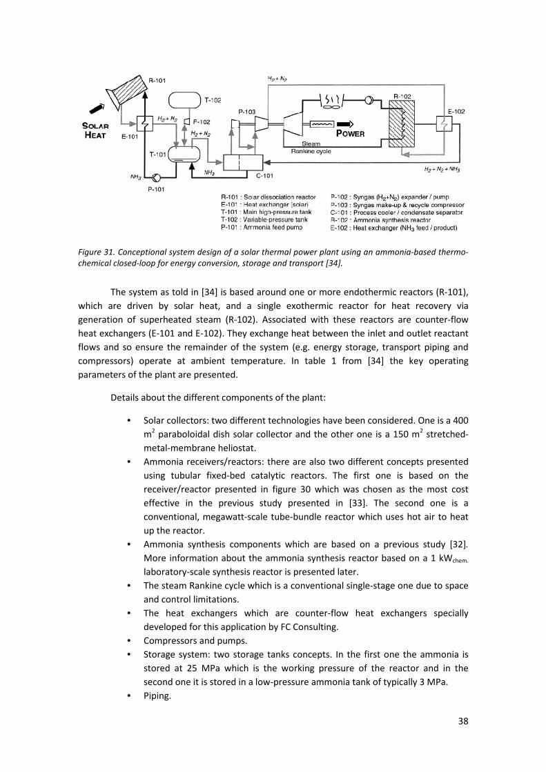
38
Figure 31. Conceptional system design of a solar thermal power plant using an ammonia-based thermo-
chemical closed-loop for energy conversion, storage and transport [34].
The system as told in [34] is based around one or more endothermic reactors (R-101),
which are driven by solar heat, and a single exothermic reactor for heat recovery via
generation of superheated steam (R-102). Associated with these reactors are counter-flow
heat exchangers (E-101 and E-102). They exchange heat between the inlet and outlet reactant
flows and so ensure the remainder of the system (e.g. energy storage, transport piping and
compressors) operate at ambient temperature. In table 1 from [34] the key operating
parameters of the plant are presented.
Details about the different components of the plant:
• Solar collectors: two different technologies have been considered. One is a 400
m2 paraboloidal dish solar collector and the other one is a 150 m
2 stretched-
metal-membrane heliostat.
• Ammonia receivers/reactors: there are also two different concepts presented
using tubular fixed-bed catalytic reactors. The first one is based on the
receiver/reactor presented in figure 30 which was chosen as the most cost
effective in the previous study presented in [33]. The second one is a
conventional, megawatt-scale tube-bundle reactor which uses hot air to heat
up the reactor.
• Ammonia synthesis components which are based on a previous study [32].
More information about the ammonia synthesis reactor based on a 1 kWchem.
laboratory-scale synthesis reactor is presented later.
• The steam Rankine cycle which is a conventional single-stage one due to space
and control limitations.
• The heat exchangers which are counter-flow heat exchangers specially
developed for this application by FC Consulting.
• Compressors and pumps.
• Storage system: two storage tanks concepts. In the first one the ammonia is
stored at 25 MPa which is the working pressure of the reactor and in the
second one it is stored in a low-pressure ammonia tank of typically 3 MPa.
• Piping.

39
with its working parameters, information about the models used and the overall performance
are presented in [34].
Finally there a preliminary cost estimation is performed based on 1997 prices, past
project experiences and quotes from European and Australian manufacturers. The result of
this estimation is shown in table 5 from [34] and the results shown are encouraging as they
indicate the potential for economic viability of this solar power plant concept. Besides the
positive economical results, it is important to remark that the first receiver/reactor concept is
more cost-effective than the second one due to a more direct energy transfer from the sun to
the ammonia system [34]. In the laboratory-scale and other experiments for the study of the
ammonia thermo-chemical energy storage systems this reactor concept is the one used.
As mentioned before, there is more information available about the ammonia
synthesis reactor in the literature [32]. Although different ammonia synthesis reactors have
been already used for other applications it is needed to perform a study about it. The reason is
that the optimized working conditions for each application vary. In the case of thermo-
chemical energy storage it is important to maximize the output of high-temperature heat for
electrical power generation in comparison to the maximization of the production rate of
ammonia which is desired in other applications.
In order to find the optimal working conditions experimental data have been recorded.
A model based on the two-dimensional pseudo-homogeneous packed-bed catalytic reactor
model mentioned before has also been validated after performing a calibration with the
experimental results. Details about the experimental results and this calibration process can be
found in [32]. The 1 kWchem. laboratory-scale scheme used in the study can be observed in
figure 32.
Figure 32. Experimental arrangement of ANU’s solar laboratory-scale closed-loop energy transfer and
storage system [32].

40
Both liquid ammonia and the 3:1 hydrogen/nitrogen gas mixture are stored at ambient
temperature and high pressure in a 20 l storage vessel. The ammonia laboratory allows
handling and analysis of reactants up to 30 MPa [32].
For dissociation, liquid ammonia is drawn from the storage vessel and passed via a
circulation pump to the nitrogen gas backed accumulator. It is subsequently passed to one of
the two receivers/reactors mentioned before [32]. The whole system operates at constant
volume and so the pressure increases as the ammonia in the vessel is dissociated [35].
For synthesis, gas is drawn from the storage vessel by a compressor pump and stored
in a 10 l buffer vessel. Subsequently, it passes through a chilled separator where some fraction
of the ammonia vapor condenses and separates from the gas and travels back to the 10 l
vessel. The purified gas continues on the heat recovery reactor which is illustrated in figure 33.
More detailed information about the laboratory installation and the measuring devices used
for testing is presented in [32] and [35].
Figure 33. The 1 kWchem. synthesis reactor [32].
It is important to mention the conclusions reached about the maximization of the
output heat. The external reactor wall temperature plays an important role in the output heat:
higher temperature contribute to higher reaction rates while an approach to chemical
41
equilibrium conditions work to reduce them. Regarding the pressure, thermal output increases
almost linearly with operating pressure.
In [35] more studies about the laboratory-scale closed-loop installation presented
before are presented. It is important to mention that the dissociation reactor used is an
improvement of the one shown in figure 30. The new version is shown in figure 34.
It differs from the previous model in that the endcap is sealed against leaks by welding
rather than using a copper gasket. It has a reduced thickness of catalyst bed, as modeling
indicated that the significantly improved heat transfer associated with higher gas velocities
strongly reduced the reactor wall operating temperature and outweighed the loss of catalyst
surface area. The reactant flow direction has also been reversed, ammonia now enters from
the base and flows through the catalyst bed toward the tip. This reversal of flow direction
allows the hot product gases to give up some of their heat to the bed as they pass back down
the centre tube. Then this new reactor uses less catalyst material [35].
Figure 34 . Ammonia dissociation reactor/receiver in operation on ANU’s 20 m2 solar concentrator [35].
An experiment with the details of the working conditions is presented in [35]. It proves
the ability of solar ammonia dissociation reactors to operate smoothly and effectively through
transients. Also the synthesis reactor was proved to work correctly as the heat was being

42
exchanged and the ammonia level at the end of the performance the ammonia level was close
to the initial conditions [35].
Finally, some considerations about the scale-up of the system to accept the 15 kWsol
input from the 20 m2 installed at ANU will be mentioned. Twenty 0,5 m long Inconel catalyst
filled tubes of similar design to the 1 kW unit are positioned in a conical arrangement around a
water-cooled cavity receiver aperture. It is shown in figure 35. The water-cooling can be
substituted by ammonia in future designs [35]. The reactor in operation can be observed in
figure 36.
Figure 35. Design of the cavity receiver with 15 kWsol solar dissociation reactor and its assembly on ANU’s
20-m2 dish without insulation fitted [35].
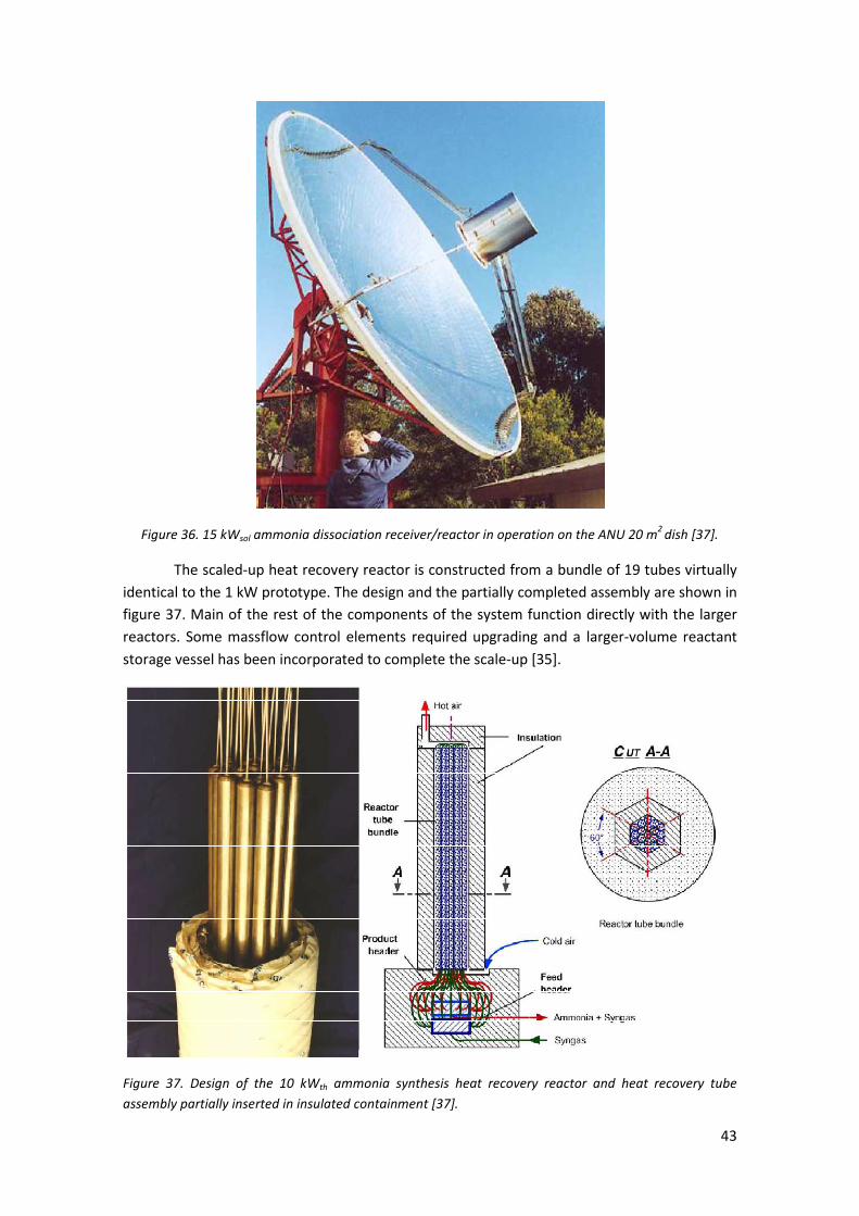
43
Figure 36. 15 kWsol ammonia dissociation receiver/reactor in operation on the ANU 20 m2
dish [37].
The scaled-up heat recovery reactor is constructed from a bundle of 19 tubes virtually
identical to the 1 kW prototype. The design and the partially completed assembly are shown in
figure 37. Main of the rest of the components of the system function directly with the larger
reactors. Some massflow control elements required upgrading and a larger-volume reactant
storage vessel has been incorporated to complete the scale-up [35].
Figure 37. Design of the 10 kWth ammonia synthesis heat recovery reactor and heat recovery tube
assembly partially inserted in insulated containment [37].
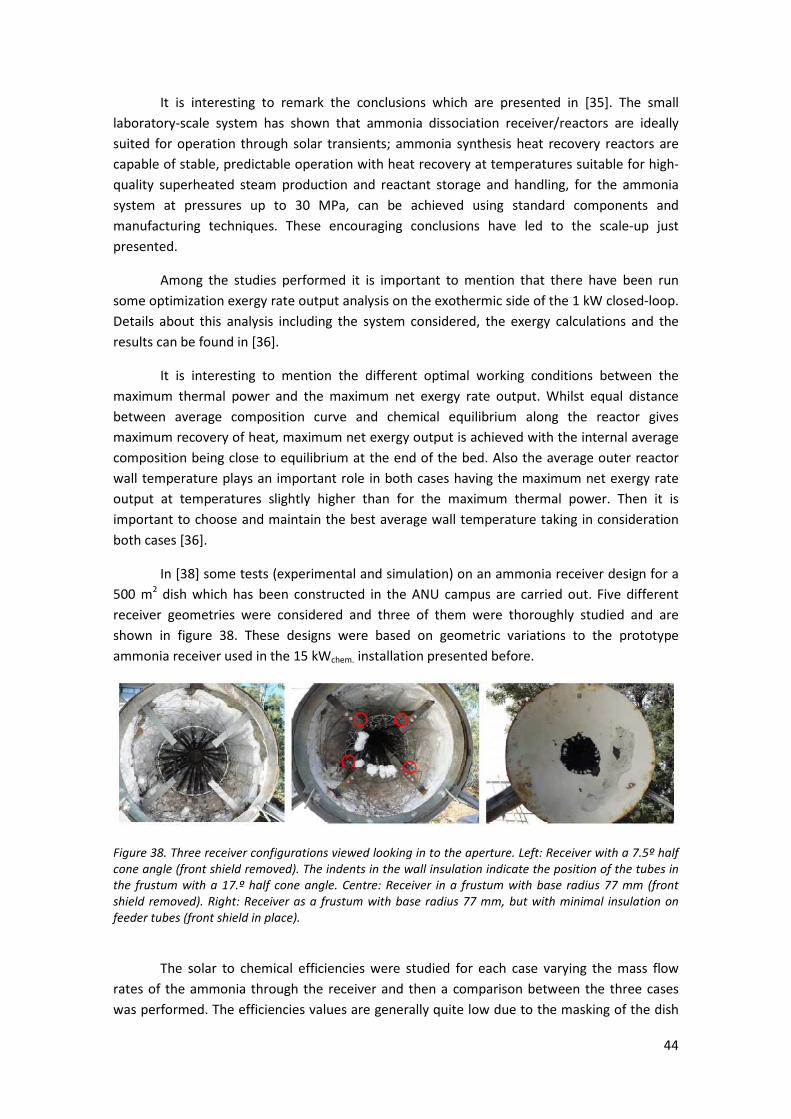
44
It is interesting to remark the conclusions which are presented in [35]. The small
laboratory-scale system has shown that ammonia dissociation receiver/reactors are ideally
suited for operation through solar transients; ammonia synthesis heat recovery reactors are
capable of stable, predictable operation with heat recovery at temperatures suitable for high-
quality superheated steam production and reactant storage and handling, for the ammonia
system at pressures up to 30 MPa, can be achieved using standard components and
manufacturing techniques. These encouraging conclusions have led to the scale-up just
presented.
Among the studies performed it is important to mention that there have been run
some optimization exergy rate output analysis on the exothermic side of the 1 kW closed-loop.
Details about this analysis including the system considered, the exergy calculations and the
results can be found in [36].
It is interesting to mention the different optimal working conditions between the
maximum thermal power and the maximum net exergy rate output. Whilst equal distance
between average composition curve and chemical equilibrium along the reactor gives
maximum recovery of heat, maximum net exergy output is achieved with the internal average
composition being close to equilibrium at the end of the bed. Also the average outer reactor
wall temperature plays an important role in both cases having the maximum net exergy rate
output at temperatures slightly higher than for the maximum thermal power. Then it is
important to choose and maintain the best average wall temperature taking in consideration
both cases [36].
In [38] some tests (experimental and simulation) on an ammonia receiver design for a
500 m2 dish which has been constructed in the ANU campus are carried out. Five different
receiver geometries were considered and three of them were thoroughly studied and are
shown in figure 38. These designs were based on geometric variations to the prototype
ammonia receiver used in the 15 kWchem. installation presented before.
Figure 38. Three receiver configurations viewed looking in to the aperture. Left: Receiver with a 7.5º half
cone angle (front shield removed). The indents in the wall insulation indicate the position of the tubes in
the frustum with a 17.º half cone angle. Centre: Receiver in a frustum with base radius 77 mm (front
shield removed). Right: Receiver as a frustum with base radius 77 mm, but with minimal insulation on
feeder tubes (front shield in place).
The solar to chemical efficiencies were studied for each case varying the mass flow
rates of the ammonia through the receiver and then a comparison between the three cases
was performed. The efficiencies values are generally quite low due to the masking of the dish
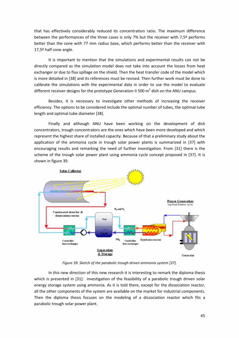
45
that has effectively considerably reduced its concentration ratio. The maximum difference
between the performances of the three cases is only 7% but the receiver with 7,5º performs
better than the cone with 77 mm radius base, which performs better than the receiver with
17,5º half cone angle.
It is important to mention that the simulations and experimental results can not be
directly compared as the simulation model does not take into account the losses from heat
exchanger or due to flux spillage on the shield. Then the heat transfer code of the model which
is more detailed in [38] and its references must be revised. Then further work must be done to
calibrate the simulations with the experimental data in order to use the model to evaluate
different receiver designs for the prototype Generation II 500 m2 dish on the ANU campus.
Besides, it is necessary to investigate other methods of increasing the receiver
efficiency. The options to be considered include the optimal number of tubes, the optimal tube
length and optimal tube diameter [38].
Finally and although ANU have been working on the development of dish
concentrators, trough concentrators are the ones which have been more developed and which
represent the highest share of installed capacity. Because of that a preliminary study about the
application of the ammonia cycle in trough solar power plants is summarized in [37] with
encouraging results and remarking the need of further investigation. From [31] there is the
scheme of the trough solar power plant using ammonia cycle concept proposed in [37]. It is
shown in figure 39.
Figure 39. Sketch of the parabolic trough driven ammonia system [37].
In this new direction of this new research it is interesting to remark the diploma thesis
which is presented in [31]: investigation of the feasibility of a parabolic trough driven solar
energy storage system using ammonia. As it is told there, except for the dissociation reactor,
all the other components of the system are available on the market for industrial components.
Then the diploma thesis focuses on the modeling of a dissociation reactor which fits a
parabolic trough solar power plant.

46
Three different concepts are investigated and presented in detail in [31]: a single tube
heat collecting reactor element (HCRE), a tube bundle HCRE and a cavity type HCRE. The
advantages and disadvantages of the different approaches and the necessary considerations in
order to adapt the concepts to a parabolic trough solar power plant are discussed also in [31].
Some simulations are run in order to test its expectable performance and to demonstrate
opportunities for further research within this field.
The design chosen was the cavity type reactor due to reduced heat loss and the ability
to expose the reactor elements to a staggered flux distribution. Some simulations varying the
diameter and ammonia feeds were performed in order to find the best nominal diameter of
the reactor which resulted to be of two inch.
To obtain constructive limits, the limits regarding pressure drop and maximal reactor
temperature were chosen, and the maximal achievable reactor length was determined out of
the result files.
Depending on the different reactor elements, length, diameter and the reaction extent
which could be expected at the corresponding massflow one design and its operation was
chosen to simulate a bench mark design for the further modeling. Depending on the results of
this bench mark a next step was performed assuming a staggered flux distribution in
comparison to the assumption of isothermally operation made in the first steps.
The results obtained from these simulations show that remarkable reaction extents
are achievable even for a non optimized reactor design regarding geometry and catalyst used.
Then, it can be concluded that the dissociation of ammonia should be achievable using a cavity
type reactor operated with the LS-3 type trough considering the assumptions taken within the
work presented in [31]. It is also concluded that the new trough design which allow a higher
temperature tolerance of the absorber could lead to higher reaction extents and thus to higher
overall efficiencies of the system [31].
1.2.3.2. The steam and the carbon dioxide reforming of methane
The reforming processes of methane are catalytic processes. In the case of the carbon
dioxide reforming of methane, the overall CO2/CH4 reaction is shown in (2) and its enthalpy of
reaction is of 247 kJ/mol at 25 ºC.
CO2 + CH4 ↔ 2 CO + 2 H2 (2)
And the thermo-chemical heat-pipes concepts using this reaction are shown in figure
40. For the storage of heat only the closes loop concept is of interest.

47
Figure 40. Concepts for (a) closed and (b) open loop thermochemical heat-pipes based on CH4/CO2
reforming and solar energy [46].
In [45] CSIRO/Pacific Power research on using the carbon dioxide reforming of
methane reaction for solar energy storage is described. Fluidised-bed reactors were chosen for
both endothermic and exothermic reactions.
Several potential catalysts were prepared and characterized for both reactions. The
CSIRO catalysts chosen were used to conduct both reacions in small-scale fluidised-bed
reactors under practical reaction condictions without carbon formation. Stable, equilibrium
CO2/CH4 reforming was obtained over a wide range of operating conditions (650 – 950 ºC, 0,1
– 0,7 MPa, 0,8 – 1,2 CO2/CH4 feed molar ratio) with thermo-chemical energy storage rates
equivalent of up to 30 MWth/tonne of catalyst being achieved. The exothermic reaction was
conducted in a fluidised-bed reactor in such a manner than more than 90 % of the reaction
heat can be recovered at temperatures around 550 ºC, thus allowing the closed loop version of
this technology to either be integrated with a conventional Rankine cycle power plant or be
used for the production of high grade process heat [46].
For the steam reforming process of methane, the reaction which takes place is shown
in (3) and the enthalpy of reaction is 206,2 kJ/molt at 25 ºC.
CH4 + H2O ↔ 3H2 + CO (3)
The same concepts as for the carbon dioxide reforming of methane can be applied but
as the temperature range needed for the reforming processes is between 750 and 950 ºC , no
further information about these two thermo-chemical reactions will be presented as it is
outside the range of interest. They have been mentioned since they are one of the most
studied and a promising technology is being developed around these two thermo-chemical
reactions [47].

48
1.2.3.3. Dehydration/Hydration cycles
1.2.3.3.1. Medium temperature (200-300ºC) chemical heat storage using mixed hydroxides
In [39] an hybrid system with a chemical heat pump and a high-temperature process is
proposed. In this case the system is focused on the efficiency enhancement of vehicles as
carbon dioxide emission due to vehicle usage has a significant impact on global warming [39].
An electric hybrid system (EHS), which combines an internal combustion engine (ICE)
with an electrical battery and a power controller as shown in figure 41, has good energy saving
performance. Upon braking, the EHS kinetically converts surplus work into electricity, which is
stored in the electrical battery. The stored electricity is used to start the vehicle or to assist
during a period of low-efficient operation of the ICE.
Figure 41. Thermal hybrid system (THS) combined with a medium-temperature chemical heat pump and
a high temperature exhaust gas from ICE, in comparison with the electric hybrid system (EHS) currently
employed in some hybrid vehicles [39].
The authors are proposing a thermal hybrid system (THS) that combines an ICE with a
thermal battery and a thermal power controller for efficient use of exhaust heat from ICE as
shown in figure 41 in comparison with the EHS. The thermal battery in THS is used for heat
storage of surplus exhaust heat from ICE. The stored heat in the thermal battery is supplied to
heat output side for tasks such as cold start, catalyst heating for exhaust gas reduction and
vehicle cabin heating. The THS is expected to contribute to load leveling of ICE operation,
improvement of fuel consumption efficiency, and reduction of CO2 emission. The THS concept
can also be applied to the cogeneration engine and solar thermal power systems [39].
Different chemical reactions were surveyed and the most promising one was the metal
oxide/water reaction (4).
MO + H2O ↔ M(OH)2 (4)
Several reactions of this type are shown in figure 2 from [39] and approach finally
chosen was a mixed between magnesium hydroxide and nickel hydroxide as it combines the
high reactivity with water vapor from magnesium oxide with the potential as new reaction
system of nickel hydroxides.
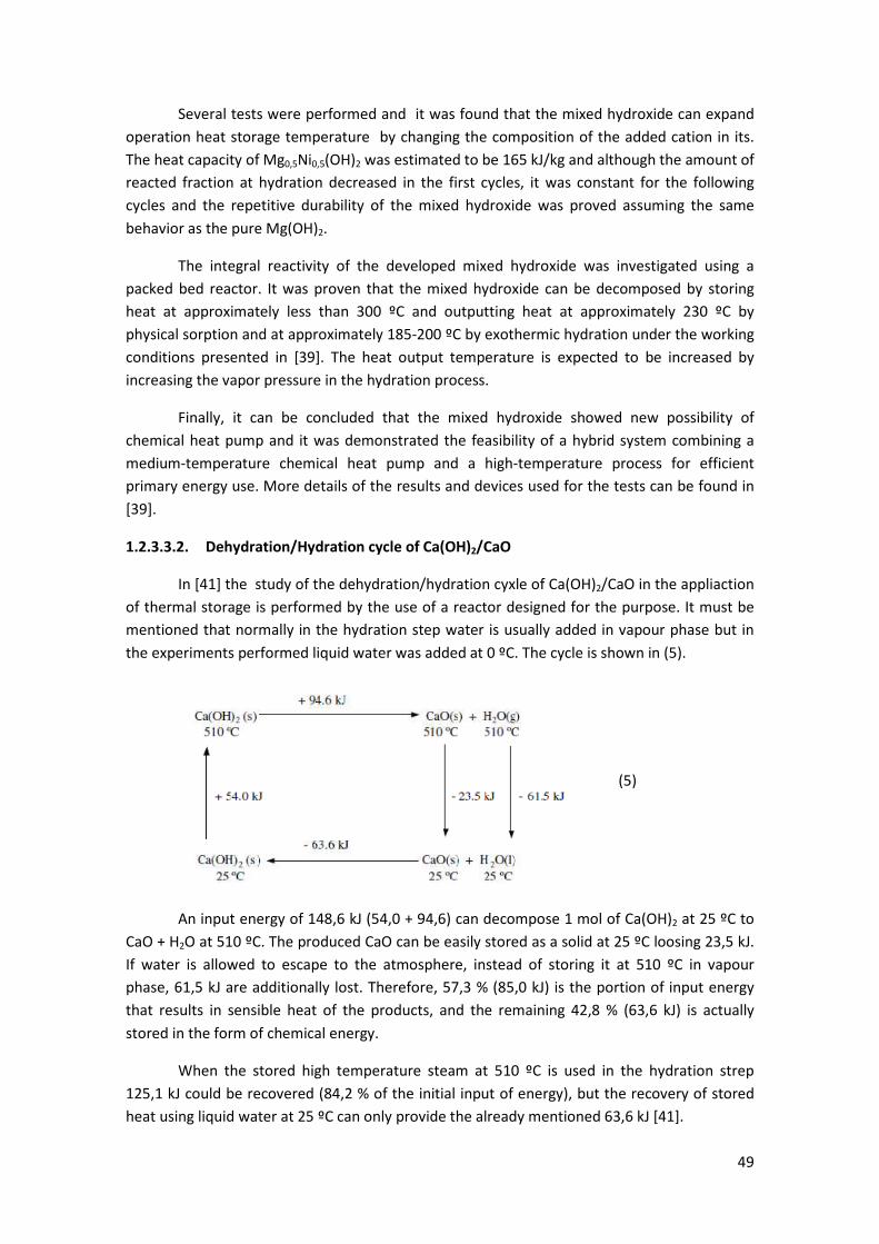
49
Several tests were performed and it was found that the mixed hydroxide can expand
operation heat storage temperature by changing the composition of the added cation in its.
The heat capacity of Mg0,5Ni0,5(OH)2 was estimated to be 165 kJ/kg and although the amount of
reacted fraction at hydration decreased in the first cycles, it was constant for the following
cycles and the repetitive durability of the mixed hydroxide was proved assuming the same
behavior as the pure Mg(OH)2.
The integral reactivity of the developed mixed hydroxide was investigated using a
packed bed reactor. It was proven that the mixed hydroxide can be decomposed by storing
heat at approximately less than 300 ºC and outputting heat at approximately 230 ºC by
physical sorption and at approximately 185-200 ºC by exothermic hydration under the working
conditions presented in [39]. The heat output temperature is expected to be increased by
increasing the vapor pressure in the hydration process.
Finally, it can be concluded that the mixed hydroxide showed new possibility of
chemical heat pump and it was demonstrated the feasibility of a hybrid system combining a
medium-temperature chemical heat pump and a high-temperature process for efficient
primary energy use. More details of the results and devices used for the tests can be found in
[39].
1.2.3.3.2. Dehydration/Hydration cycle of Ca(OH)2/CaO
In [41] the study of the dehydration/hydration cyxle of Ca(OH)2/CaO in the appliaction
of thermal storage is performed by the use of a reactor designed for the purpose. It must be
mentioned that normally in the hydration step water is usually added in vapour phase but in
the experiments performed liquid water was added at 0 ºC. The cycle is shown in (5).
An input energy of 148,6 kJ (54,0 + 94,6) can decompose 1 mol of Ca(OH)2 at 25 ºC to
CaO + H2O at 510 ºC. The produced CaO can be easily stored as a solid at 25 ºC loosing 23,5 kJ.
If water is allowed to escape to the atmosphere, instead of storing it at 510 ºC in vapour
phase, 61,5 kJ are additionally lost. Therefore, 57,3 % (85,0 kJ) is the portion of input energy
that results in sensible heat of the products, and the remaining 42,8 % (63,6 kJ) is actually
stored in the form of chemical energy.
When the stored high temperature steam at 510 ºC is used in the hydration strep
125,1 kJ could be recovered (84,2 % of the initial input of energy), but the recovery of stored
heat using liquid water at 25 ºC can only provide the already mentioned 63,6 kJ [41].
(5)
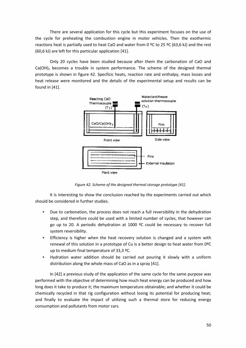
50
There are several application for this cycle but this experiment focuses on the use of
the cycle for preheating the combustion engine in motor vehicles. Then the exothermic
reactions heat is partially used to heat CaO and water from 0 ºC to 25 ºC (63,6 kJ) and the rest
(60,6 kJ) are left for this particular application [41].
Only 20 cycles have been studied because after them the carbonation of CaO and
Ca(OH)2 becomes a trouble in system performance. The scheme of the designed thermal
prototype is shown in figure 42. Specficic heats, reaction rate and enthalpy, mass losses and
heat release were monitored and the details of the experimental setup and results can be
found in [41].
Figure 42. Scheme of the designed thermal storage prototype [41].
It is interesting to show the conclusion reached by the experiments carried out which
should be considered in further studies.
• Due to carbonation, the process does not reach a full reversibility in the dehydration
step, and therefore could be used with a limited number of cycles, that however can
go up to 20. A periodic dehydration at 1000 ºC could be necessary to recover full
system reversibility.
• Efficiency is higher when the heat recovery solution is changed and a system with
renewal of this solution in a prototype of Cu is a better design to heat water from 0ºC
up to medium final temperature of 33,3 ºC.
• Hydration water addition should be carried out pouring it slowly with a uniform
distribution along the whole mass of CaO as in a spray [41].
In [42] a previous study of the application of the same cycle for the same purpose was
performed with the objective of determining how much heat energy can be produced and how
long does it take to produce it; the maximum temperature obtainable; and whether it could be
chemically recycled in that rig configuration without losing its potential for producing heat;
and finally to evaluate the impact of utilizing such a thermal store for reducing energy
consumption and pollutants from motor cars.
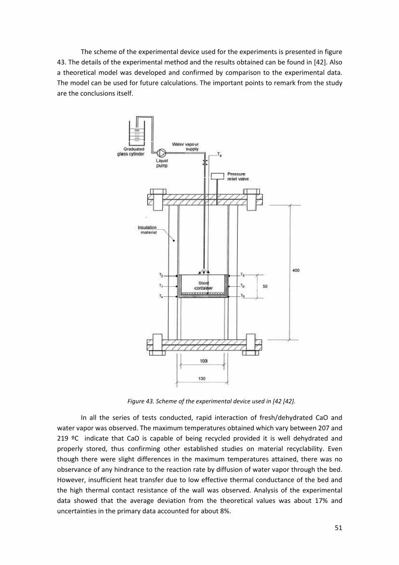
51
The scheme of the experimental device used for the experiments is presented in figure
43. The details of the experimental method and the results obtained can be found in [42]. Also
a theoretical model was developed and confirmed by comparison to the experimental data.
The model can be used for future calculations. The important points to remark from the study
are the conclusions itself.
Figure 43. Scheme of the experimental device used in [42 [42].
In all the series of tests conducted, rapid interaction of fresh/dehydrated CaO and
water vapor was observed. The maximum temperatures obtained which vary between 207 and
219 ºC indicate that CaO is capable of being recycled provided it is well dehydrated and
properly stored, thus confirming other established studies on material recyclability. Even
though there were slight differences in the maximum temperatures attained, there was no
observance of any hindrance to the reaction rate by diffusion of water vapor through the bed.
However, insufficient heat transfer due to low effective thermal conductance of the bed and
the high thermal contact resistance of the wall was observed. Analysis of the experimental
data showed that the average deviation from the theoretical values was about 17% and
uncertainties in the primary data accounted for about 8%.
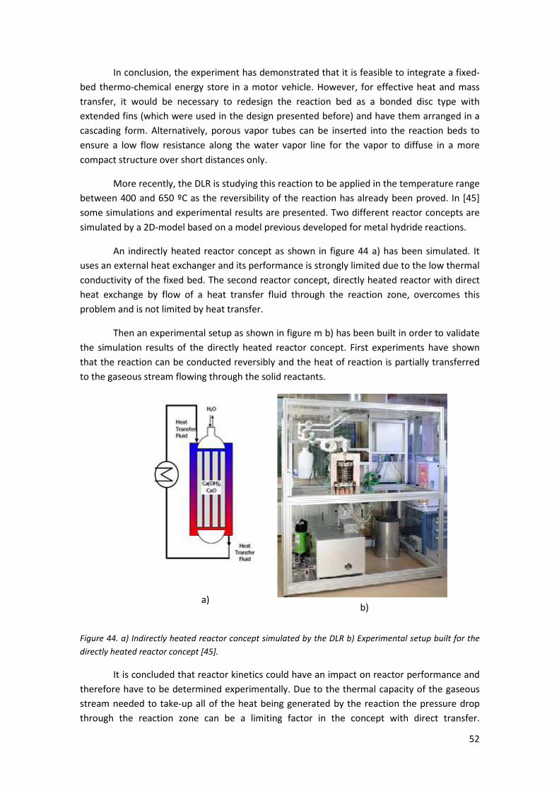
52
In conclusion, the experiment has demonstrated that it is feasible to integrate a fixed-
bed thermo-chemical energy store in a motor vehicle. However, for effective heat and mass
transfer, it would be necessary to redesign the reaction bed as a bonded disc type with
extended fins (which were used in the design presented before) and have them arranged in a
cascading form. Alternatively, porous vapor tubes can be inserted into the reaction beds to
ensure a low flow resistance along the water vapor line for the vapor to diffuse in a more
compact structure over short distances only.
More recently, the DLR is studying this reaction to be applied in the temperature range
between 400 and 650 ºC as the reversibility of the reaction has already been proved. In [45]
some simulations and experimental results are presented. Two different reactor concepts are
simulated by a 2D-model based on a model previous developed for metal hydride reactions.
An indirectly heated reactor concept as shown in figure 44 a) has been simulated. It
uses an external heat exchanger and its performance is strongly limited due to the low thermal
conductivity of the fixed bed. The second reactor concept, directly heated reactor with direct
heat exchange by flow of a heat transfer fluid through the reaction zone, overcomes this
problem and is not limited by heat transfer.
Then an experimental setup as shown in figure m b) has been built in order to validate
the simulation results of the directly heated reactor concept. First experiments have shown
that the reaction can be conducted reversibly and the heat of reaction is partially transferred
to the gaseous stream flowing through the solid reactants.
Figure 44. a) Indirectly heated reactor concept simulated by the DLR b) Experimental setup built for the
directly heated reactor concept [45].
It is concluded that reactor kinetics could have an impact on reactor performance and
therefore have to be determined experimentally. Due to the thermal capacity of the gaseous
stream needed to take-up all of the heat being generated by the reaction the pressure drop
through the reaction zone can be a limiting factor in the concept with direct transfer.
a) b)
53
Experiments are currently under way to investigate the influence of various operating
conditions and to get close to the commercial demonstration of thermo-chemical energy
storage.
1.2.3.3.3. Ni-doped and undoped Mg-MgH2 materials
In [44] the use of Ni-doped and undoped Mg-MgH2 materials for thermo-chemical heat
storage in the temperature range of 450-500 ºC is also studied. It is proved that both types of
materials have excellent cyclic stability and high hydrogenation rates. Several cycling tests are
carried out focusing mainly on the causes of hydrogen capacity losses and finding the
operational conditions which minimize these losses.
Details about the experimental devices, the samples of the materials and the cycling
tests are detailed in [44] with their respective results. It is important to mention that the
properties of the different materials are sensitively dependent upon all the details of the
experimental cycling conditions: hydrogenation/dehydrogenation pressure and temperature,
distance to the equilibrium conditions, time allotted for hydrogenation/dehydrogenation
processes, the temperature regime of heating and cooling and the previous cyclization history
of the material sample.
The conclusion is that these materials can be applied for applications such as solar
generation of heat and cold, heat pumps, hydrogen storage, solar power generation via Stirling
engine and storage of industrial heat in the temperature range of 450 to 500 ºC [44].
1.2.3.3.4. Mg2FeH6
The reversible Mg2FeH6 hydride system has been studied as an option for thermo-
chemical storage at approximately 500 ºC. In [43] there is a report about the thermodynamic
properties and cyclic stability of this system by an elemental analysis, themovolumetry, X-ray
powder diffraction, PCI measurements and transmission electron microscopy . The preparation
of the different samples and experimental devices used and the experiences carried out are
presented in [43].
The reaction with its enthalpy of reaction (77,4 kJ/mol H2) resulted to be the one
shown in (6).
2Mg + Fe + 3H ↔ Mg2FeH6+ 77.4 kJ/mol H2 (6)
A comparison between this system and the MgH2 system is also performed reaching to
the conclusion that Mg2FeH6 shows a lower hydrogen dissociation pressure which is favorable
from technical and economical points of view, since the required heat storage containers
would be less costly and the H2 leakage rate would be reduced.
Also the mixed Mg2FeH6-MgH2 is studied and characterized resulting to be also a
potential thermo-chemical hydrogenation/dehydrogenation system.
The conclusions are that these two systems have got a higher gravimetric and
volumetric thermal energy density than the sensible or latent heat storage materials and the
stability in cycle tests at around 500 ºC has been proved. Further advantages include the low
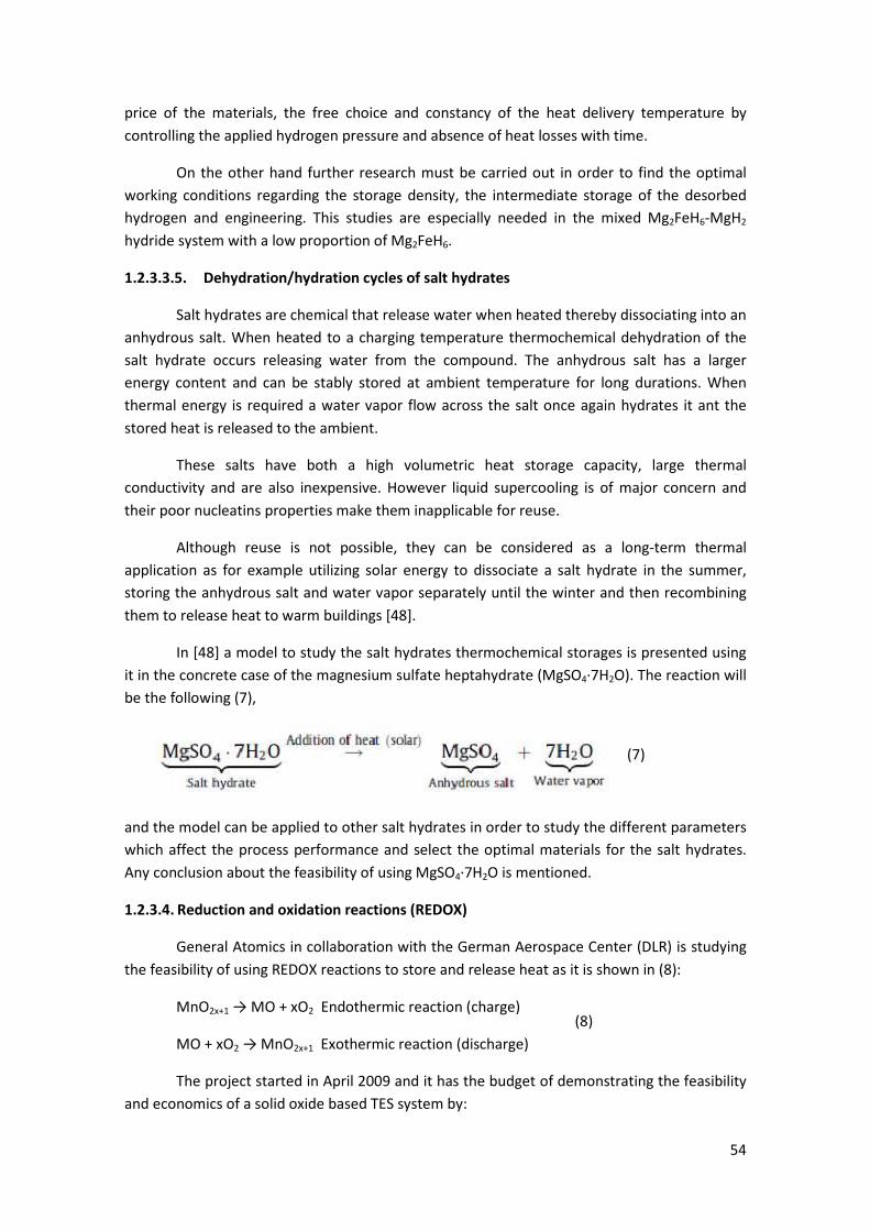
54
price of the materials, the free choice and constancy of the heat delivery temperature by
controlling the applied hydrogen pressure and absence of heat losses with time.
On the other hand further research must be carried out in order to find the optimal
working conditions regarding the storage density, the intermediate storage of the desorbed
hydrogen and engineering. This studies are especially needed in the mixed Mg2FeH6-MgH2
hydride system with a low proportion of Mg2FeH6.
1.2.3.3.5. Dehydration/hydration cycles of salt hydrates
Salt hydrates are chemical that release water when heated thereby dissociating into an
anhydrous salt. When heated to a charging temperature thermochemical dehydration of the
salt hydrate occurs releasing water from the compound. The anhydrous salt has a larger
energy content and can be stably stored at ambient temperature for long durations. When
thermal energy is required a water vapor flow across the salt once again hydrates it ant the
stored heat is released to the ambient.
These salts have both a high volumetric heat storage capacity, large thermal
conductivity and are also inexpensive. However liquid supercooling is of major concern and
their poor nucleatins properties make them inapplicable for reuse.
Although reuse is not possible, they can be considered as a long-term thermal
application as for example utilizing solar energy to dissociate a salt hydrate in the summer,
storing the anhydrous salt and water vapor separately until the winter and then recombining
them to release heat to warm buildings [48].
In [48] a model to study the salt hydrates thermochemical storages is presented using
it in the concrete case of the magnesium sulfate heptahydrate (MgSO4·7H2O). The reaction will
be the following (7),
and the model can be applied to other salt hydrates in order to study the different parameters
which affect the process performance and select the optimal materials for the salt hydrates.
Any conclusion about the feasibility of using MgSO4·7H2O is mentioned.
1.2.3.4. Reduction and oxidation reactions (REDOX)
General Atomics in collaboration with the German Aerospace Center (DLR) is studying
the feasibility of using REDOX reactions to store and release heat as it is shown in (8):
MnO2x+1 → MO + xO2 Endothermic reaction (charge)
MO + xO2 → MnO2x+1 Exothermic reaction (discharge)
The project started in April 2009 and it has the budget of demonstrating the feasibility
and economics of a solid oxide based TES system by:
(8)
(7)

55
• Indentifying and select the multivalent oxide based TES systems that have the
potential to meet the economical targets.
• Evaluating and demonstrating their feasibility experimentally.
• Determining the process economics based on the data obtained.
Achieving these targets, CSP will be competitive in the intermediate power market by 2015
and baseloadmarket by 2020 [40].
Sixteen pure oxides were found to be able to undergo REDOX in air based on
thermodynamics calculation with their respective equilibrium reaction temperatures and
energy density storage are shown in figure 45.
Figure 45. Equilibrium reaction temperature and potential energy storage density for various oxides in air
[40].
From these sixteen oxides Cr5O12, Li2O2, Mg2O, PtO2, UO3 and Rh2O3 were eliminated
based on transition temperatures and raw material costs. Then an experimental protocol
which is detailed in [40] was establised in order to test and characterize the candidates left.
It is important to mention that in the temperature range of interest (200-700 ºC) no
large scale re-oxidation was observed in thermochemical candidates. Nevertheless in the range
of 700 to 1100 ºC, Co3O4 was chosen as a feasible candidate as it demonstrated full re-
oxidation. Heat charge and discharge in a TES packed bed was shown using the cobalt oxide
and further studies will be performed in the next phases of the project.
Finally, re-oxidation kinetics improvement and long term stability of the low cost
oxides via secondary oxide incorporation will be key to large scale deployment of this TES
concept with CSP and will allow to make feasible other oxides which have been previously
mentioned. More details about the project, the time horizon of the different phases and
budgets can be found in [40].
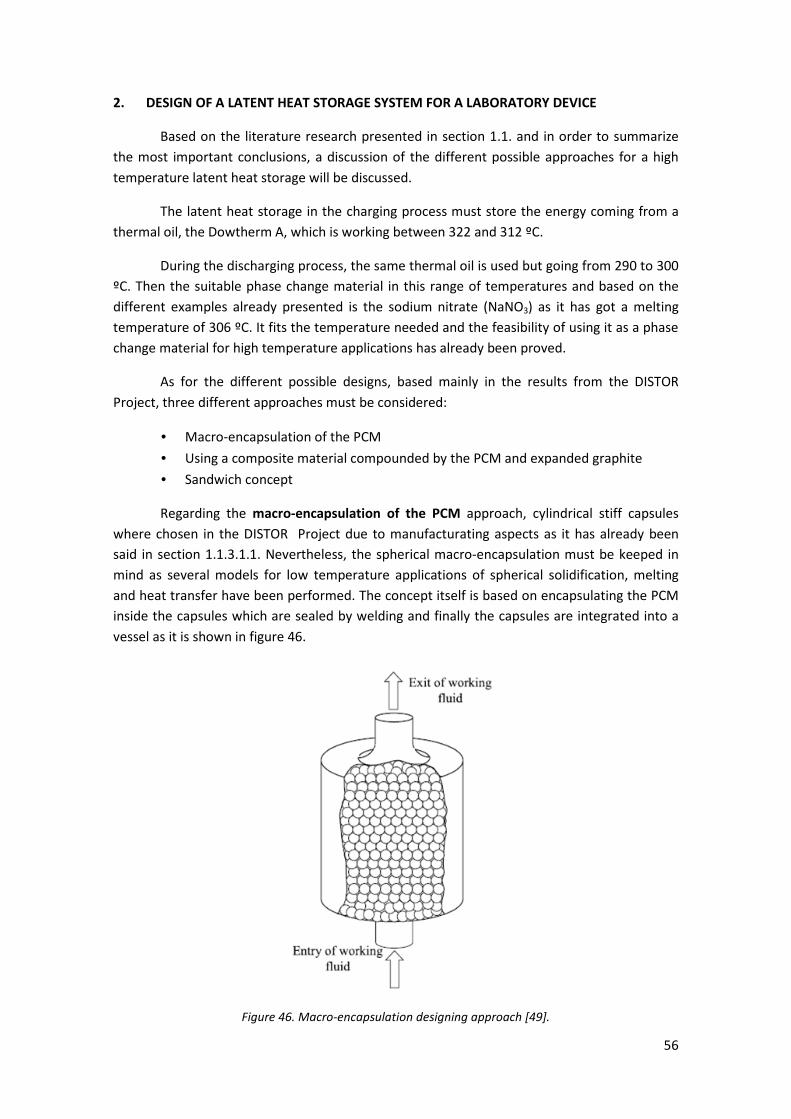
56
2. DESIGN OF A LATENT HEAT STORAGE SYSTEM FOR A LABORATORY DEVICE
Based on the literature research presented in section 1.1. and in order to summarize
the most important conclusions, a discussion of the different possible approaches for a high
temperature latent heat storage will be discussed.
The latent heat storage in the charging process must store the energy coming from a
thermal oil, the Dowtherm A, which is working between 322 and 312 ºC.
During the discharging process, the same thermal oil is used but going from 290 to 300
ºC. Then the suitable phase change material in this range of temperatures and based on the
different examples already presented is the sodium nitrate (NaNO3) as it has got a melting
temperature of 306 ºC. It fits the temperature needed and the feasibility of using it as a phase
change material for high temperature applications has already been proved.
As for the different possible designs, based mainly in the results from the DISTOR
Project, three different approaches must be considered:
• Macro-encapsulation of the PCM
• Using a composite material compounded by the PCM and expanded graphite
• Sandwich concept
Regarding the macro-encapsulation of the PCM approach, cylindrical stiff capsules
where chosen in the DISTOR Project due to manufacturating aspects as it has already been
said in section 1.1.3.1.1. Nevertheless, the spherical macro-encapsulation must be keeped in
mind as several models for low temperature applications of spherical solidification, melting
and heat transfer have been performed. The concept itself is based on encapsulating the PCM
inside the capsules which are sealed by welding and finally the capsules are integrated into a
vessel as it is shown in figure 46.
Figure 46. Macro-encapsulation designing approach [49].
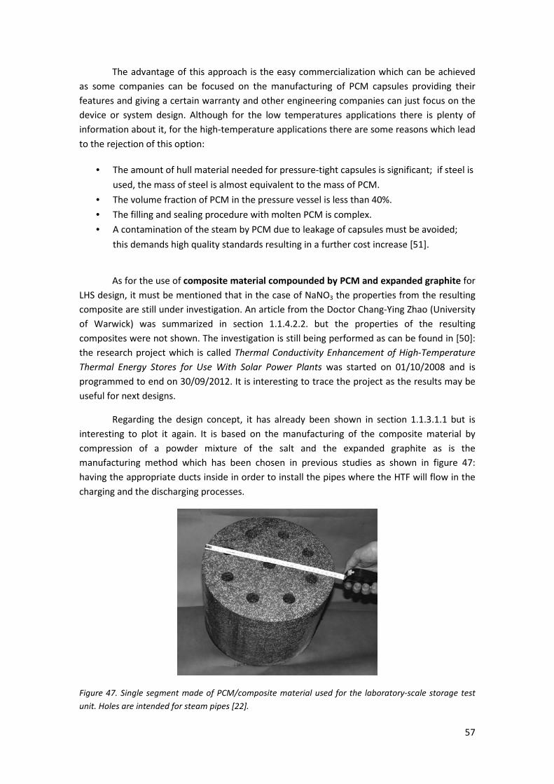
57
The advantage of this approach is the easy commercialization which can be achieved
as some companies can be focused on the manufacturing of PCM capsules providing their
features and giving a certain warranty and other engineering companies can just focus on the
device or system design. Although for the low temperatures applications there is plenty of
information about it, for the high-temperature applications there are some reasons which lead
to the rejection of this option:
• The amount of hull material needed for pressure-tight capsules is significant; if steel is
used, the mass of steel is almost equivalent to the mass of PCM.
• The volume fraction of PCM in the pressure vessel is less than 40%.
• The filling and sealing procedure with molten PCM is complex.
• A contamination of the steam by PCM due to leakage of capsules must be avoided;
this demands high quality standards resulting in a further cost increase [51].
As for the use of composite material compounded by PCM and expanded graphite for
LHS design, it must be mentioned that in the case of NaNO3 the properties from the resulting
composite are still under investigation. An article from the Doctor Chang-Ying Zhao (University
of Warwick) was summarized in section 1.1.4.2.2. but the properties of the resulting
composites were not shown. The investigation is still being performed as can be found in [50]:
the research project which is called Thermal Conductivity Enhancement of High-Temperature
Thermal Energy Stores for Use With Solar Power Plants was started on 01/10/2008 and is
programmed to end on 30/09/2012. It is interesting to trace the project as the results may be
useful for next designs.
Regarding the design concept, it has already been shown in section 1.1.3.1.1 but is
interesting to plot it again. It is based on the manufacturing of the composite material by
compression of a powder mixture of the salt and the expanded graphite as is the
manufacturing method which has been chosen in previous studies as shown in figure 47:
having the appropriate ducts inside in order to install the pipes where the HTF will flow in the
charging and the discharging processes.
Figure 47. Single segment made of PCM/composite material used for the laboratory-scale storage test
unit. Holes are intended for steam pipes [22].

58
The shape of the composite block, position of the ducts and dimensions can be varied
depending on the working conditions in order to achieve the optimal design. It must be
remembered that there is an analytical model with some assumptions presented in [25] which
can be useful once the results from Dr. C.Y. Zhao are published. The conclusion is that this
option must be rejected as the feasibility of the composite material approach could not be
proven for nitrate salts so far [51].
Finally the sandwich concept approach which is the one chosen as the best solution in
the DISTOR Project was already presented in sections 1.1.3.1.1 and 1.1.4.1. As the melting
temperature of the sodium nitrate is 306 ºC, aluminum fins are the ones that must be used in
this case.
The feasibility of this approach with high capacity factors, as mentioned in [27], has
already been proved in different storage units ranging from 2 to 100 kW. Because of that, this
option is the one chosen for the design of the latent heat storage system for the laboratory
device which is shown in figure 48. It can be observed several valves, pumps and the heating
source and heat since which can be chosen depending on the process required: charging and
discharging processes respectively. The temperatures shown in figure 48 are the ones
corresponding to the charging process.
Figure 48. Laboratory device where the LHS will be installed.
59
A part from choosing the latent heat storage material and the configuration of the
system, the designing parameters are:
• The latent heat storage power: 30 kW.
• The heat transfer fluid: Dowtherm A. The properties of the fluid which have
been used for the calculations presented in the following section can be found
in [56].
• The volumetric flow: 6 m3/h and a velocity of around 1 m/s.
• The temperatures in the charging process from the Dowtherm A: 322 ºC in the
beginning and 312 ºC in the end.
• The temperatures in the discharging process from the Dowtherm A: 290 ºC in
the beginning and 300 ºC in the end.
• The maximum dimensions: 2 m3
• Charging and discharging time of 2 hours: energy capacity of 60 kWh.
Once the design has been chosen (sandwich concept) and the main designing
parameters are clearly listed, it is possible to model it in order to choose the geometrical
parameters and observe the behavior of the system.
Due to the complexity of the problem, the model presented in the following section is
a preliminary and approximate model which can be only seen as a way of having an initial idea
of how the temperature profiles evolve and a trial to prove the feasibility between the design
chosen and the designing parameters. Before building the system for the experimental device,
further studies and modeling performances must be carried out, including software and
simulation tools such as FLUENT, Mathcad and Mathlab.
2.1. Modeling of the latent heat storage system
2.1.1. The Classical Stefan Problem
The calculation of a latent heat storage system is based on the Classical Stefan
Problem. The complexity of the problem due to the unknown location of the interface
between the solid and liquid results in the need of making several assumptions.
These assumptions are presented in the following table comparing them to the real
situation:

60
Physical Factors Involved in
Phase Change Processes
(real situation)
Simplifying Assumptions for
the Stefan Problem
Remarks on the assumptions
Heat and mass transfer by
conduction, convection,
radiation with possible
gravitational, elastic,
chemical and
electromagnetic effects.
Heat transfer isotropically by
conduction only, all other
effects assumed negligible.
Most common case. Very
reasonable for pure
materials, small container,
moderate temperature
gradients.
Release or absorption of
latent heat.
Latent heat is constant; it is
released or absorbed at the
phase-change temperature.
Very reasonable and
consistent with the rest of
assumptions.
Variation of phase-change
temperature.
Phase-change temperature is
a fixed known temperature, a
property of the material.
Most common case,
consistent with other
assumptions.
Nucleation difficulties,
supercooling effects.
Assume not present. Reasonable in many
situations.
Interface thickness and
structure.
Assume locally planar and
sharp (a surface separating
the phases) at the phase-
change temperature.
Reasonable for many pure
materials (no internal heating
present).
Surface tension and
curvature effects at the
interface.
Assume insignificant. Reasonable and consistent
with other assumptions.
Variation of thermophysical
properties.
Assume constant in each
phase, for simplicity.
An assumption of
convenience only.
Reasonable for most
materials under moderate
temperature range
variations. The significant
aspect is their discontinuity
across the interface, which is
allowed.
Density changes. Assume constant (rL = rS). Necessary assumption to
avoid movement of material.
Possibly the most
unreasonable of the
assumptions.
Table 7. Assumptions made in the Classical Stefan Problem [55].
Several models have been built around the Stefan problem which in some cases add
some accuracy to the assumptions shown in table 7. For further details about these models,
the reviews shown in [57] and [58] and the book mentioned in [59] are interesting.
In this Master Thesis due to time and resources limiting factors, the model performed
is a simplified one and has got the target of using an analytical solution of the Stefan Problem:
the quasi-static approximation. The effects of sensible heat are neglected and thanks to that
the energy equation becomes independent of time and solutions are much easier to obtain.

61
For the case of interest, the equations which will be used are the ones corresponding
to a Cartesian Coordinate geometry as the Stefan Problem is a non-linear problem and it is not
possible to obtain the results from the steel cylinder and the aluminum fins and add them at
the end. Because of that, the heat transfer from the steel tube is neglected and only the heat
transfer from the aluminum fins considering Cartesian coordinates is taken into account.
The general equations governing the process for the quasi-static approximation are
the following:
-(./ = [2 · 2(3 · ℎ (
· � [��(./ − ��5 · �.5�
6
&/+ 89: . ≥ 0
Equation 3. Position of the liquid-solid interface in the melting process of a semi-infinite solid [60]
�((=, ./ = ��(./ − >��(./ − �?@ · =-(./ AB 0 ≤ = ≤ -(./ 89: . ≥ 0
Equation 4. Temperature profile of the liquid region in the melting process of a semi-infinite solid [60]
As it can be observed in equations 3 and 4, there is the need to obtain the temperature
profile of the aluminum fins in the non-steady state. An analytical solution for a hollow
cylinder with radial fins along the cylinder in the external surface does not exist and there is
the need to use numerical methods to solve the problem. The finite volume model built for the
purpose is presented in the following section.
2.1.2. The finite volume model
The finite volume model developed can be observed in figure 49 with the
corresponding nodal numeration. It takes into account only one fin and has got 13 nodes,
the last three of them are contour nodes and their temperature is already known:
• Node 11 is the phase-change material and it is at its melting temperature as the
sensible heat is neglected in the quasi-static approximation and no supercooling is
considered in the Classical Stefan Problem as mentioned before.
• Node 12 corresponds to the Dowtherm A and the heat transfer with the steel tube is
by convection.
• Node 13 is the contour of the steel tube in its extremities from z direction and it is
considered the same temperature in both of the sides (symmetry from the horizontal
axis of the fin).
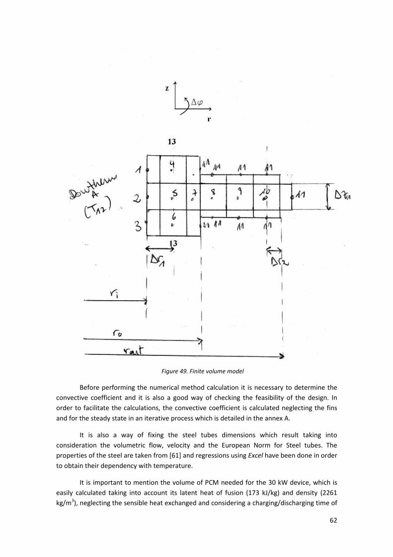
62
Figure 49. Finite volume model
Before performing the numerical method calculation it is necessary to determine the
convective coefficient and it is also a good way of checking the feasibility of the design. In
order to facilitate the calculations, the convective coefficient is calculated neglecting the fins
and for the steady state in an iterative process which is detailed in the annex A.
It is also a way of fixing the steel tubes dimensions which result taking into
consideration the volumetric flow, velocity and the European Norm for Steel tubes. The
properties of the steel are taken from [61] and regressions using Excel have been done in order
to obtain their dependency with temperature.
It is important to mention the volume of PCM needed for the 30 kW device, which is
easily calculated taking into account its latent heat of fusion (173 kJ/kg) and density (2261
kg/m3), neglecting the sensible heat exchanged and considering a charging/discharging time of
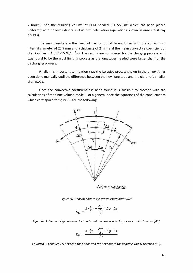
63
2 hours. Then the resulting volume of PCM needed is 0.551 m3 which has been placed
uniformly as a hollow cylinder in this first calculation (operations shown in annex A if any
doubts).
The main results are the need of having four different tubes with 6 steps with an
internal diameter of 22.9 mm and a thickness of 2 mm and the mean convective coefficient of
the Dowtherm A of 1715 W/(m2·K). The results are considered for the charging process as it
was found to be the most limiting process as the longitudes needed were larger than for the
discharging process.
Finally it is important to mention that the iterative process shown in the annex A has
been done manually until the difference between the new longitude and the old one is smaller
than 0.001.
Once the convective coefficient has been found it is possible to proceed with the
calculations of the finite volume model. For a general node the equations of the conductivities
which correspond to figure 50 are the following:
Figure 50. General node in cylindrical coordinates [62].
D%& = 2 · E:% + ∆:2 F · ∆G · ∆H∆:
Equation 5. Conductivity between the i-node and the next one in the positive radial direction [62].
D%, = 2 · E:% − ∆:2 F · ∆G · ∆H∆:
Equation 6. Conductivity between the i-node and the next one in the negative radial direction [62].
64
D%+ = 2 · ∆: · ∆H:% · ∆G = D%I
Equation 7. Conductivity between the i-node and the neighbor in the G direction (both sides) [62].
DJK = 2 · :% · ∆G · ∆:∆H = DJL
Equation 8. Conductivity between the i-node and the neighbor in the z direction (either up and down)
[62].
It is important to mention that due to symmetry the conductivities in the f direction
are not taken into account, there is only heat transfer in two dimensions: z and r. That leads to
use for all the nodes an Df of 2p and also is important to remark that F=f in figure 50.
Also there is the need to choose the numerical method resolution: in this case the
implicit method as the properties of the different materials are considered constant with
temperature and in this method there is not any problems with stability and convergence in
the solutions.
Once the conductivities for each node are calculated, it is possible to define the
conductivity matrix (KT), the conductivity contour matrix (KC), the temperature contour nodes
vector (TC), the CDT matrix which is needed as it is the unsteady state and it is possible to
calculate the final temperatures (TF) after each time interval (2 s) supposing for the first time
interval a first temperature vector of the nodes: in this case 579 K as it is the temperature of
the steel tube from the calculations presented before (annex A).
The matrix solution is then:
�M = (D� − �N�/L& =(−D�=�� − �N�=�O/
Equation 9. Matrix solution of the unsteady state for the implicit method [62].
and the details about all the procedure, with the conductivities defined for each node and the
matrixes mentioned before can be found in the annex B for the first time interval.
The steady state is reached after 6 seconds and the temperature profile in front of
time of the nodes of the aluminum fins (8,9 and 10) are plotted in the following two figures as
the results for node 9 and 10 are the same.

65
Figure 51. Temperature profile for the unsteady state of node 8.
Figure 52. Temperature profile for the unsteady state of nodes 9 and 10.
As for the contour conditions, the PCM has been considered at a constant
temperature: the melting temperature. The results show that the temperature of the nodes of
the fin is not enough high as the heat flux between the Dowtherm A and the aluminum fins is
not enough.
Then in order to calculate the time needed for the melting of the PCM, after all the
assumptions made, it is reasonable enough to consider a constant temperature five degrees
above the melting temperature for the aluminum fin which should be the target of future
designs.
Then the time it takes for the solid-liquid interface to get to the most extreme area: 2
mm far away from the fin is from equation 3 and considering T0(t) = 311 ºC = constant:
. = -(./+ · 3 · ℎ (2 · P( · (�6 − ��/ = 0.006 +�+ · 2261PT/�, · 173300W/PT
2 · 0.5Y/(� · D/ · 5D = 2821 [ = 0.78 ℎ
Then, using equation 3, it is possible to have a bigger distance between fins than the
one initially selected as it is possible to have a charging time of 2 hours:
-(7200/ = \2 · 0.5 Y/(� · D/2261PT/�, · 173300W/PT · 5D · 7200[]
6.^= 0.009 �
It must be mentioned that all the calculations presented in both annex A and annex B are
based on several chapters from [62].
2 4 6 8
305.99
305.995
T9
∆tgraph
2 4 6 8305.995
306
306.005
T8
∆tgraph
66
3. CONCLUSION
A review of the latent heat storage systems which can be found for high temperature
applications has been performed. A great progress has already been achieved with several
models and laboratory devices which have been built. Nevertheless there is still work to do in
order to reach to the commercialization of LHS devices for high temperature.
There are still some challenges which must be overcome and specially the low thermal
conductivity of the phase change materials which are normally used. In this direction, different
approaches have been studied and the sandwich concept is the most successful at the
moment as it has already been mentioned. Nevertheless, the macro-encapsulation of PCM, the
use of composites and the use of metallic materials are interesting approaches which must be
followed and studied further.
In addition, a review on thermo-chemical storage systems has been shown. Although it is
a newer topic than the LHS systems, there is also a great work already developed specially with
the dissociation of ammonia, the dehydration/hydration cycles and the reduction and
oxidation reactions. As in the case of the LHS systems, there is a long way to reach the
commercialization level but to have an idea of when it can be enough developed it is
interesting to remark that the reduction and oxidation reactions project already mentioned
has got the target of reaching the commercialized level between 2015 and 2020.
Finally, an initial design of a LHS system for a laboratory device has been presented. The
model is limited as the phase-change is a non-linear problem which has a complex
mathematical modeling. The sandwich concept was the design chosen and some first
calculations were performed including a simple finite volume model in order to have a first
idea of the behavior and the temperature profiles of the system. Software with adequate
simulations tools for the problem must be used in the future to continue the modeling of the
system and finish the detailing of the design specially because at the moment the heat flux
between the heat transfer fluid and the aluminum fins is not enough. An option to overcome
the situation could be the reconsideration of the designing parameters such as the input and
output temperature of the heat transfer fluid (Dowtherm A).
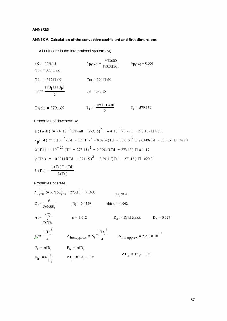
67
ANNEXES
ANNEX A. Calculation of the convective coefficient and first dimensions
∆T F TdF Tm−:=
All units are in the international system (SI)
eK 273.15:=
Twall 579.169:=
Properties of dowtherm A:
Di 0.0229:=
Properties of steel λs Ts( ) 5.7168 Ts 273.15−( )⋅ 71.685−:=
thick 0.002:=
VPCM60 3600⋅173.3 2261⋅
:= VPCM 0.551=
TdI 322 eK+:=
TdF 312 eK+:= Tm 306 eK+:=
TdTdI TdF+( )
2:= Td 590.15=
TsTm Twall+
2:= Ts 579.159=
µ Twall( ) 5 109−× Twall 273.15−( )
2⋅ 4 106−× Twall 273.15−( )− 0.001+:=
cp Td( ) 3 105−⋅ Td 273.15−( )
30.0206 Td 273.15−( )
2− 8.0348 Td 273.15−( )+ 1082.7+:=
λ Td( ) 1020−
Td 273.15−( )2
0.0002 Td 273.15−( )⋅− 0.1419+:=
ρ Td( ) 0.0014− Td 273.15−( )2⋅ 0.2911 Td 273.15−( )⋅− 1020.3+:=
Pr Td( )µ Td( ) cp Td( )⋅
λ Td( ):=
Nt 4:=
Q6
3600Nt⋅:=
u4 Q⋅
Di2 π⋅
:= u 1.012= Do Di 2thick+:= Do 0.027=
Sπ Di
2⋅
4:= Afirstapprox Nt
π Do2⋅
4⋅:= Afirstapprox 2.273 10
3−×=
Pt π Di⋅:= Ph π Di⋅:=
Dh 4S
Ph
⋅:= ∆T I TdI Tm−:=

68
MLDT∆T I ∆T F−
ln∆T I∆T F
:=
G ρ TdI( ) u⋅:=
Turbulent flow
n 0.25:=
L 6.574:=
Twallnew q Rss⋅ Tm+:=
np 6:=
ReGDh⋅
µ Td( ):= Re 7.721 10
4×=
φµ Td( )
µ Twall( ):=
q Q ρ Td( )⋅ cp Td( )⋅ TdI TdF−( )⋅:=
Cfm1
1.58 ln Re( )⋅ 3.28−( )2
:= Cfm 4.755 103−×=
Nu
Cfm Re 1000−( )⋅ Pr Td( )⋅ 1Dh
L
2
3
+
⋅ φ n⋅
2 17.96Cfm0.5⋅ Pr Td( )
2
31−
⋅+
:=
hdNu λ Td( )⋅
Dh
:= hd 1.715 103×=
As π Di⋅ L⋅:=
Rs1
hd As⋅:= Rss
lnDo
Di
2 π⋅ λs Ts( )⋅ L⋅:=
Us1
As Rs Rss+( )⋅:=
Lnewq
Us π⋅ Di MLDT⋅:= Lnew 6.574=
Twallnew 579.169=
Error Lnew L−:= Error 1.542− 104−×=
Vtubes π Do⋅ Lnew⋅:= Vtubes 0.556=
Vtotal Vtubes VPCM+:=Lstep
L
np
:=
Vtotal 1.107=
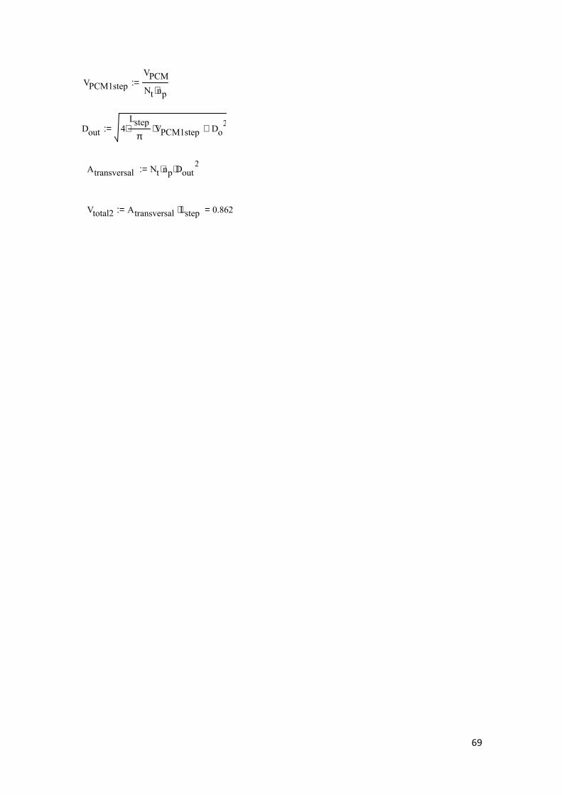
69
VPCM1step
VPCM
Nt np⋅:=
Dout 4Lstep
π⋅ VPCM1step⋅ Do
2+:=
Atransversal Nt np⋅ Dout2⋅:=
Vtotal2 Atransversal Lstep⋅ 0.862=:=
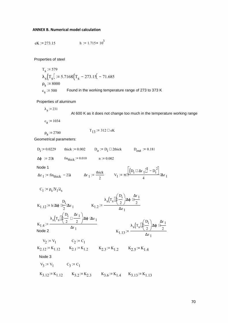
70
ANNEX B. Numerical model calculation
eK 273.15:=
Properties of steel
Ts 579:=
λs Ts( ) 5.7168 Ts 273.15−( )⋅ 71.685−:=
ρs 8000:=
cs 500:=
Properties of aluminum
λa 231:=
At 600 K as it does not change too much in the temperature working range
ca 1034:=
ρa 2700:=
Geometrical parameters:
Di 0.0229:= thick 0.002:=
finthick 0.010:= n 0.002:=
Node 1
Node 2
K2.12 K1.12:=
K2.1 K1.2:=
K2.3 K1.2:=
K2.5 K1.4:=
Node 3
K3.12 K1.12:=
K3.2 K2.3:=
K3.6 K1.4:= K3.13 K1.13:=
Found in the working temperature range of 273 to 373 K
h 1.715 103×:=
T13 312 eK+:=
Do Di 2thick+:= Dout 0.181:=
∆ϕ 2 π⋅:=
∆z 1 finthick 2 n⋅−:= ∆r 1thick
2:= V1 π
Di ∆r 1+( )2 Di2−
4⋅ ∆z 1⋅:=
C1 ρs V1⋅ cs⋅:=
K1.12 h ∆ϕ⋅Di
2⋅ ∆z 1⋅:= K1.2
λs Ts( )Di
2
⋅ ∆ϕ⋅∆r 12
⋅
∆z 1:=
K1.4
λs Ts( )Di
2
∆r 12
+
⋅ ∆ϕ⋅ ∆z 1⋅
∆r 1:=
K1.13
λs Ts( )Di
2
⋅ ∆ϕ⋅∆r 12
⋅
∆z 1:=
V2 V1:= C2 C1:=
V3 V1:= C3 C1:=

71
Node 4
Node 5
K5.2 K2.5:= K5.6 K4.5:=
K5.4 K4.5:=
Node 6
K6.3 K3.6:=
K6.5 K5.6:=
K6.11 K4.11:=
K6.13 K4.13:=
Node 7
K7.5 K5.7:=
C4 ρs V4⋅ cs⋅:=
K4.1 K1.4:= K4.5
λ s Ts( )Di
2∆r 1+
⋅ ∆ϕ⋅ ∆r 1⋅
∆z 1:= K4.13
λ s Ts( )Di
2∆r 1+
⋅ ∆ϕ⋅ ∆r 1⋅
∆z 1:=
K4.11
λ s T s( )Di
2∆ r 1+
∆ r 12
+
⋅ ∆ϕ⋅ ∆ z 1⋅
∆ r 1:=
V5 V4:= C5 C4:=
K5.7
λs Ts( )Di
2∆r 1+
3
4
∆r 12
⋅+
⋅ ∆ϕ⋅ ∆z 1⋅
∆r 12
∆r 14
+
:=
V6 V4:= C6 C4:=
V7 πDi 4∆r 1+( )2 Di 3∆r 1+( )2−
4⋅ ∆z 1⋅:= C7 ρs V7⋅ cs⋅:=
K7.11 2
λs Ts( )Di
2∆r 1+
∆r 12
+∆r 14
+
⋅ ∆ϕ⋅∆r 12
⋅
∆z 1⋅:=
Rm7
∆r 1
4
λs Ts( )Di
2∆r 1+
∆r 12
+∆r 14
+
⋅ ∆ϕ⋅ ∆z 1⋅
:= ∆r 2
Dout
2
Do
2−
7:=
Rm8
∆r 2
λaDi
2∆r 1+
∆r 12
+∆r 14
+
⋅ ∆ϕ⋅ ∆z 1⋅
:= K7.81
Rm7 Rm8+:=
V4 πDi 3∆r 1+( )2 Di ∆r 1+( )2−
4⋅ ∆z 1⋅:=

72
Nodes from the aluminum fin
Node 8
K8.7 K7.8:=
Node 9
K9.8 K8.9:=
Node 10
K10.9 K9.10:=
V8 πDo 4∆r 2+( )2 Do( )2−
4⋅ ∆z 1⋅:= C8 ρa V8⋅ ca⋅:=
K8.11 2
λaDout
26 ∆r 2⋅−
⋅ ∆ϕ⋅ 2⋅ ∆r 2⋅
∆z 1⋅:=
K8.9
λaDo
2∆r 2+ ∆r 2+
⋅ ∆ϕ⋅ ∆z 1⋅
2 ∆r 2⋅:=
V9 πDo 8∆r 2+( )2 Do 4∆r 2+( )2−
4⋅ ∆z 1⋅:= C9 ρa V9⋅ ca⋅:=
K9.11 2
λaDo
23 ∆r 2⋅+
⋅ ∆ϕ⋅ 2⋅ ∆r 2⋅
∆z 1⋅:=
K9.10
λaDo
23∆r 2+ ∆r 2+
⋅ ∆ϕ⋅ ∆z 1⋅
2 ∆r 2⋅:=
V10 πDo 12∆r 2+( )2 Do 8∆r 2+( )2−
4⋅ ∆z 1⋅:= C10 ρa V10⋅ ca⋅:=
K10.11 2
λaDo
25 ∆r 2⋅+
⋅ ∆ϕ⋅ 2⋅ ∆r 2⋅
∆z 1⋅
λaDo
25∆r 2+ ∆r 2+
⋅ ∆ϕ⋅ ∆z 1⋅
2 ∆r 2⋅+:=
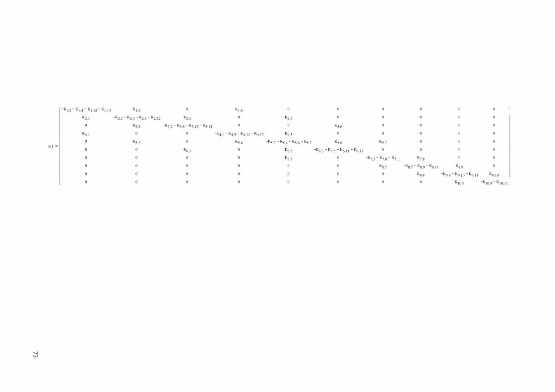
KT
K1.2
− K1.4
− K1.12
− K1.13
−
K2.1
0
K4.1
0
0
0
0
0
0
K1.2
K2.1
− K2.3
− K2.5
− K2.12
−
K3.2
0
K5.2
0
0
0
0
0
0
K2.3
K3.2
− K3.6
− K3.12
− K3.13
−
0
0
K6.3
0
0
0
0
K1.4
0
0
K4.1
− K4.5
− K4.11
− K4.13
−
K5.4
0
0
0
0
0
0
K2.5
0
K4.5
K5.2
− K5.4
− K5.6
− K5.7
−
K6.5
K7.5
0
0
0
0
0
K3.6
0
K5.6
K6.3
− K6.5
− K6.11
− K6.13
−
0
0
0
0
0
0
0
0
K5.7
0
K7.5
− K7.8
− K7.11
−
K8.7
0
0
0
0
0
0
0
0
K7.8
K8.7
− K8.9
− K8.11
−
K9.8
0
0
0
0
0
0
0
0
K8.9
K9.8
− K9.10
− K9.11
−
K10.9
0
0
0
0
0
0
0
0
K9.10
K10.9
− K10.11
−
:=
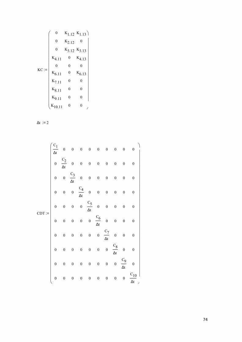
74
∆t 2:=
KC
0
0
0
K4.11
0
K6.11
K7.11
K8.11
K9.11
K10.11
K1.12
K2.12
K3.12
0
0
0
0
0
0
0
K1.13
0
K3.13
K4.13
0
K6.13
0
0
0
0
:=
CDT
C1
∆t
0
0
0
0
0
0
0
0
0
0
C2
∆t
0
0
0
0
0
0
0
0
0
0
C3
∆t
0
0
0
0
0
0
0
0
0
0
C4
∆t
0
0
0
0
0
0
0
0
0
0
C5
∆t
0
0
0
0
0
0
0
0
0
0
C6
∆t
0
0
0
0
0
0
0
0
0
0
C7
∆t
0
0
0
0
0
0
0
0
0
0
C8
∆t
0
0
0
0
0
0
0
0
0
0
C9
∆t
0
0
0
0
0
0
0
0
0
0
C10
∆t
:=
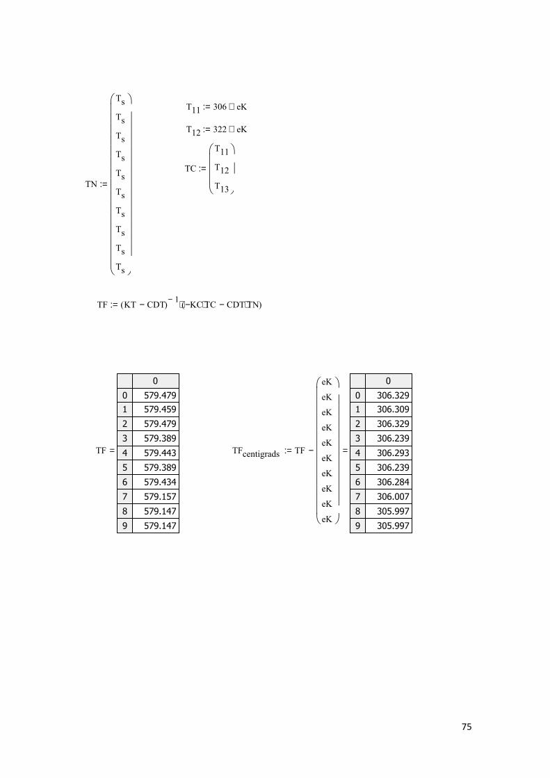
75
T11 306 eK+:=
T12 322 eK+:=
TC
T11
T12
T13
:=
TN
Ts
Ts
Ts
Ts
Ts
Ts
Ts
Ts
Ts
Ts
:=
TF KT CDT−( )1−
KC− TC⋅ CDT TN⋅−( )⋅:=
TF
0
0
1
2
3
4
5
6
7
8
9
579.479
579.459
579.479
579.389
579.443
579.389
579.434
579.157
579.147
579.147
= TFcentigrads TF
eK
eK
eK
eK
eK
eK
eK
eK
eK
eK
−
0
0
1
2
3
4
5
6
7
8
9
306.329
306.309
306.329
306.239
306.293
306.239
306.284
306.007
305.997
305.997
=:=
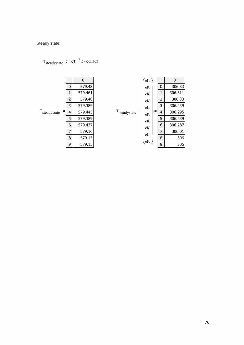
76
Steady state:
Tsteadystate KT1−
KC− TC⋅( )⋅:=
Tsteadystate
0
0
1
2
3
4
5
6
7
8
9
579.48
579.461
579.48
579.389
579.445
579.389
579.437
579.16
579.15
579.15
= Tsteadystate
eK
eK
eK
eK
eK
eK
eK
eK
eK
eK
−
0
0
1
2
3
4
5
6
7
8
9
306.33
306.311
306.33
306.239
306.295
306.239
306.287
306.01
306
306
=

77
REFERENCES
[1] Review on thermal energy storage with phase change materials and applications, A.
Sharma, Kun Shan University.
[2] Latent heat storage in concrete, Dipl.-Ing. Jens H. Dieckmann, University of Kaiserslautern.
[3] High-temperature phase change materials for thermal energy storage, Murat M. Kenisarin,
Uzbekistan Academy of Sciences.
[4] George A. Handbook of thermal design. In: Guyer C, editor. Phase change thermal storage
materials. McGraw Hill Book Co.; 1989 [chapter 1].
[5] Technology of latent heat storage for high temperature application: a review, ISIJ
International, Vol. 50 (2010), No. 9, pp. 1229–1239.
[6] Experimental research on a kind of novel high-temperature phase change storage heater.
Energy Convers Manage 2006, Wang X, Liu J, Zhang Y, Di H, Jiang Y.
[7] Heat storage media; Rainer Tamme (DLR), Thomas Bauer (DLR), Erich Hahne (University of
Stuttgart).
[8] State of the art on high temperature thermal energy storage for power generation. Part 1-
Concepts, materials and modellization; Antoni Gil, Marc Medrano, Ingrid Martorell, Ana
Lázaro, Pablo Dolado, Belen Zalba, Luisa F. Cabeza.
[9] Evaluation of molten salt power tower technology based on the experience of solar two,
Reilly HE, Kolb WJ, SANDIA report SAND2001-3674; 2001.
[10] Cascaded latent heat storage for parabolic trough solar power plants; Horst Michels,
Robert Pitz-Paal; Deutsches Zentrum für Luft- und Raumfahrt (DLR), Solar Research, Linder Hö
he, 51147 Cologne, Germany; 2006.
[11] Thermal energy storage for commercial application (TESCA), a feasibility study on
economic storage systems; Dinter, F., Geyer, M., Tamme, R.; Springer-Verlag, Berlin, 1991.
[12] Overview on thermal storage systems, FLABEG Solar International GmbH, 2002
[13] State of the art on high temperature thermal energy storage for power generation. Part 2-
Case studies; Antoni Gil, Marc Medrano, Ingrid Martorell, Ana Lázaro, Pablo Dolado, Belen
Zalba, Luisa F. Cabeza.
[14] Thermal energy storage for direct steam generation; Doerte Laing et al.; Institute of
Technical Thermodynamics, Stuttgart, Germany.
[15] Advanced high temperature latent heat storage system – design and test results; D. Laing,
T. Bauer, W.-D. Steinmann, D. Lehmann; Institute of Technical Thermodynamics, German
Aerospace Center (DLR), 2009.
78
[16] Heat Transfer and Latent Heat Storage in Inorganic Molten Salts for Concentrating Solar
Thermal Power Plants, Anoop Mathur, June 5 2009
[17] Heat Transfer and Latent Heat Storage in Inorganic Molten Salts for Concentrating Solar
Thermal Power Plants, Anoop Mathur, May 26 2010
[18] Screening of high melting point phase change materials (PCM) in solar thermal
concentrating technology based on CLFR; Akira Hoshi et al.; Department of Mechanical
Engineering, Ichinoseki National College of Technology, Takanashi, Hagisho, Ichinoseki 021-
8511, Japan, 2004.
[19] http://www.dlr.de/tt/desktopdefault.aspx/tabid-2872/4415_read-6488/
[20] INDITEP: The first pre-commercial DSG solar power plant; Eduardo Zarza et al.; Plataforma
Solar de Almería, CIEMAT, Apartado P.O. Box 22, 04200 Tabernas, Almería, Spain; 2005
[21] DISTOR Project: Thermal Storage in solar-thermal plants; Francisco Javier Gala Lupiani;
Iberdrola
[22] Latent Heat Storage for Solar Steam Systems; Rainer Tamme; German Aerospace Center
(DLR), Institute of Technical Thermodynamics, Pfaffenwaldring 38-40, 70569 Stuttgart,
Germany
[23] Annual report from Plataforma Solar de Almería 2007
[24] Biannual report from Plataforma Solar de Almería 2008 – 2009
http://es.scribd.com/doc/45800380/Plataforma-Solar-de-Almeria-Annual-Report-2008-2009
[25] Thermal energy storage systems for electricity production using solar energy direct steam
generation technology; Vincent Morisson; TREFLE UMR 8508, Esplanade des Arts et M´etiers,
33405 Talence Cedex, France; 2007
[26] Analysis of the experimental behavior of a 100 kWth latent heat storage system for direct
steam generation in solar thermal power plants; Rocío Bayón, Esther Rojas, Loreto Valenzuela,
Eduardo Zarza, Javier León; 2010
[27] Advanced high temperature latent heat storage system-design and test results; D. Laing,
T. Bauer, W.-D. Steinmann, D. Lehmann; Institute of Technical Thermodynamics, German
Aerospace Center (DLR) Pfaffenwaldring 38-40, 70569 Stuttgart, Germany
[28] Performance enhancement in latent heat thermal: a review; S. Jegadheeswaran, Sanjay D.
Pohekar; Mechanical Engineering Area, Tolani Maritime Institute, Induri, Talegaon-Chakan
Road, Pune 410 507, India, 2009
[29] Highly conductive composites made of phase change materials and graphite for thermal
storage; S. Pincemin, R. Olives, X. Py, M. Christ; Solar Energy Materials & Solar Cells 92 (2008)
603–613

79
[30] Heat transfer enhancement of high temperature thermal energy storage using metal
foams and expanded graphite; C.Y. Zhao, Z.G.Wu; School of Engineering, University of
Warwick, Coventry CV4 7AL, UK, 2010.
[31] Investigation of the feasibility of a parabolic trough driven solar energy storage system
using ammonia; Marc Scheffler; Diploma Thesis
[32] Theoretical analysis and experimental results of a 1kW ammonia synthesis reactor for a solar thermo-chemical energy storage system; H. Kreetz; Centre for Sustainable Energy Systems, Department of Engineering, Australian National University, Canberra ACT 0200, Australia, 1999 [33] Endothermic reactors for an ammonia based thermo-chemical solar energy storage and transport system; K Lovegrove; Energy Research Centre/Department of Engineering, Australian National University, Canberra ACT 0200, Australia, 1996 [34] Techno-economic analysis of a 10 MWe solar thermal power plant using ammonia-based thermo-chemical energy storage; Andreas Luzzi; Centre for Sustainable Energy Systems, Australian National University (ANU), Canberra ACT 0200, Australia, 1998 [35] A solar-driven ammonia-based thermo-chemical energy storage system; Keith Lovegrove; Centre for Sustainable Energy Systems, Department of Engineering, Australian National University, Canberra, ACT 0200, Australia, 1999 [36] Exergy analysis of an ammonia synthesis reactor in a solar thermo-chemical power system; H. Kreetz; Centre for Sustainable Energy Systems, Department of Engineering, Australian National University, Canberra ACT 0200, Australia, 2002 [37] Developing ammonia based thermo-chemical energy storage for dish power plants; K. Lovegrove; Department of Engineering, Centre for Sustainable Energy Systems, Australian National University, Canberra ACT 0200, Australia, 2003 [38] Ammonia receiver design for a 500 m2 dish; Rebecca Dunn; Solar Thermal Group, Australian National University (ANU), Department of Engineering, Building 32 North Rd, ACT 0200, Australia. [39] Study on medium-temperature chemical heat storage using mixed hydroxides; Yukitaka Kato; Research Laboratory for Nuclear Reactors, Tokyo Institute of Technology, 2-12-1-N1-22, Ookayama, Meguro-ku, Tokyo 152-8550, Japan, 2009 [40] Thermochemical heat storage for concentrated solar power, General Atomics, Award number: DE-FG-36-08GO18145 DOE Solar Program Review, 2010 [41] Heat recovery from a thermal energy storage based on the Ca(OH)2/CaO cycle; M.N. Azpiazu; Departamento de Ingeniería Química y del Medio Ambiente, E.T.S. Ingenieros (UPV/EHU), Alda. Urquijo s/n, 48013 Bilbao, Spain, 2003 [42] Thermo-chemical energy storage in inorganic oxides: an experimental evaluation; K. Darkwa; Applied Energy and Environmental Engineering Unit, Department of Building and Environmental Health, Nottingham Trent University, Burton Street, Nottingham NG1 4BU, UK, 1997
80
[43] Thermodynamics and dynamics of the Mg–Fe–H system and its potential for thermo-chemical thermal energy storage; Borislav Bogdanovic; Max-Planck-Institut für Kohlenforschung, Kaiser-Wilhelm-Platz 1, D-45470 Mülheim an der Ruhr, Germany, 2002 [44] Ni-doped versus undoped Mg–MgH materials for high temperature heat or hydrogen storage; Borislav Bogdanovic; Max-Planck-Institut für Kohlenforschung, Kaiser-Wilhelm-Platz 1, D-45470 Mülheim an der Ruhr, Germany, 1999 [45] High temperature thermo-chemical heat storage for CSP using gas-solid reactions; Franziska Schaube; German Aerospace Center – DLR e.V., Pfaffenwaldring 38-40, 70569 Stuttgart, Germany [46] The use of solar-based CO2/CH4 reforming for reducing greenhouse gas emissions during the generation of electricity and process heat; J. H. Edwards, CSIRO Coal and Energy Technology, 51 Delhi Rd, North Ryde, NSW, 2113, Australia, 1996. [47] Catalyst application in solar thermo-chemistry; V. A. Kirillow; Boreskov Institute of Catalysis, Pr. Akad. Lavrentieva 5, 630090 Novosibirsk, Russia, 1999 [48] Modeling of thermo-chemical energy storage by salt hydrates; Ganesh Balasubramanian, Department of Engineering Science and Mechanics, Virginia Polytechnic Institute and State University, Blacksburg, VA 24061, USA, 2010 [49] Numerical and experimental study of spherical capsules packed bed latent heat storage system; K.A.R. Ismail; Departamento de Engenharia T_ermica e de Fluidos, FEM, UNICAMP, Caixa Postal 6122, CEP 13083-970 Campinas, SP, Brazil, 2002 [50] Expertise profile of Doctor Chang-Ying Zhao, http://www2.warwick.ac.uk/fac/sci/eng/research/profile/cyz/
[51] Latent heat storage systems for solar thermal power plants and process heat applications, Wolf-Dieter Steinmann; http://www.nrel.gov/docs/gen/fy08/42709CD.zip --> 42709_1i_4.pdf [52] An experimental study on heat transfer characteristics of heat pipe heat exchanger with latent heat storage. Part I: Charging only and discharging only modes; Zhongliang Liu; Key Laboratory of Enhanced Heat Transfer and Energy Conservation, Ministry of Education and Key Laboratory of Heat Transfer and Energy Conversion, Beijing Education Commission, College of Environmental and Energy Engineering, Beijing University of Technology, Beijing 100022, PR China, 2005 [53] High temperature latent heat thermal energy storage using heat pipes; H. Shabgard; Department of Mechanical Engineering, The University of Connecticut, 191 Auditorium Road, Unit 3139 Storrs, CT 06269, USA, 2010 [54] Heat transfer efficient thermal energy storage for steam generation; R. Adinberg; Solar Research Facilities, Weizmann Institute of Science, Rehovot 76100, Israel, 2009
[55] Mathematical modeling of melting and freezing processes; Alexiades Vasilios; Hemisphere Publications, 1993
81
[56] Product information, Dowtherm A, Synthetic Organic Heat Transfer Fluid—Liquid and Vapor Phase Data, DOW [57] A review of materials, heat transfer and phase change problem formulation for latent heat thermal energy storage systems (LHTESS), Francis Agyenim, Centre for Sustainable Technologies, University of Ulster, Newtownabbey BT37 0QB, UK, 2009 [58] A review on phase-change materials: Mathematical modeling and simulations, Yvan Dutil, Chaire de Recherche Industrielle T3E, École de technologie supérieure, Université du Québec, 801 Boul. Mgr, Bourget Lévis, QC G6V 9V6, Canada, 2010 [59] Thermal energy storage : systems and applications; Ibrahim Dinçer; Chichester, England: Wiley, cop. 2002 [60] Handbook of Thermal Engineering; Frank Kreith; CRC Pr., 2000 [61] Properties of steel: http://www.azom.com/article.aspx?ArticleID=863
[62] Transferència de calor : apunts de classe. Bonals Muntada, Lluís Albert. Barcelona : CPDA. ETSEIB, 2005