High Temperature Electrolysis System
15
High Temperature Electrolysis System Dr. Steve Herring Idaho National Laboratory May 19, 2009 Project ID # PD_14_Herring This presentation does not contain any proprietary, confidential, or otherwise restricted information
Transcript of High Temperature Electrolysis System

High TemperatureElectrolysis System
Dr. Steve HerringIdaho National Laboratory
May 19, 2009
Project ID # PD_14_Herring
This presentation does not contain any proprietary, confidential, or otherwise restricted information

2
• Project start date: Jan. 2003, button cells
• Project end date: Engr. Demo (1 MW), 2015
(MYPP p. 3.1-24)• G. Capital Cost Development of larger
systems is also needed to take advantage of economies of scale.
• H. System Efficiency New membrane, electrode and system designs are needed to improve system efficiency
• I. Grid Electricity Emissions Low-cost, carbon-free electricity generation is needed. Electrolysis systems that can produce both hydrogen and electricity need to be evaluated.
• Total project funding– All DOE-NE
• Funding received in FY08: $3559k• Funding for FY09: $2588k
Timeline
Budget
Barriers
• Massachusetts Institute of Technology• Ceramatec, Inc.• St. Gobain Ceramics• Materials & Systems Research, Inc.• NASA – Glenn Research Center • Argonne National Laboratory• Virginia Tech, Georgia Tech (NERI projects) • Project lead: Idaho National Laboratory
Partners
Overview

3
• Objectives – Over Life of Project– Develop an economical method for the CO2-free production of hydrogen in
centralized facilities– Configure the plant for the integration of heat and electricity from a nuclear
reactor and for interactions with the grid to accept or supply power as wind/solar sources vary
• Objectives – June 2008 - May 2009– Construction and Operation of the three-module Integrated Laboratory Scale
experiment for long-duration (>1000 hrs) – Organization and sponsorship of a Workshop on SOEC Degradation with
experts from the SOFC/SOEC community– Characterization of degraded cells to determine silicon/chromium transport,
delamination and destabilization of electrolyte– Tests of short stacks and button cells of other designs and from other
manufacturers– Build capability to simultaneously run five small tests– Due to budget constraints, flowsheet modeling and CFD have been stopped
for FY-09
Relevance

4
FY 2008 Milestones• Demonstrate improved performance of oxygen and steam hydrogen electrodes through
the deposition of electrocatalytic materials by the ALD or other infiltration processes. (ANL) 9/30/2008
• Test plan for ILS operations with three modules 5/15/2008• Report on O2 handling and cooling options based on collaboration with AECL
7/2/2008 • Three module test in the ILS at 15 kW input power. 9/15/2008• Analysis report on corrosion testing of the second series of BOP materials
9/30/2008FY 2009 Milestones• Long-term Operation of ILS [Completed 10/20/08, 1080 hours]• Report on experimental data from the operation of the HTE ILS experiment
(2/27/2009) [Completed and uploaded to PICS 2/17/09]• Report on critical causes of stack degradation in ILS cells (5/29/2009)• Report on long-term testing of 10-cell stacks degradation (8/14/2009)• Complete 2500 hr 10-cell stack test (9/14/09)• Report on insights gained from testing of alternative cell designs (9/15/2009)
Relevance
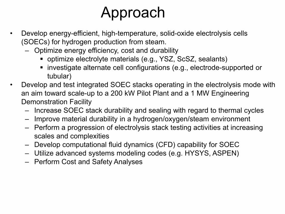
Approach• Develop energy-efficient, high-temperature, solid-oxide electrolysis cells
(SOECs) for hydrogen production from steam.– Optimize energy efficiency, cost and durability
optimize electrolyte materials (e.g., YSZ, ScSZ, sealants)investigate alternate cell configurations (e.g., electrode-supported or tubular)
• Develop and test integrated SOEC stacks operating in the electrolysis mode with an aim toward scale-up to a 200 kW Pilot Plant and a 1 MW Engineering Demonstration Facility– Increase SOEC stack durability and sealing with regard to thermal cycles– Improve material durability in a hydrogen/oxygen/steam environment– Perform a progression of electrolysis stack testing activities at increasing
scales and complexities – Develop computational fluid dynamics (CFD) capability for SOEC– Utilize advanced systems modeling codes (e.g. HYSYS, ASPEN)– Perform Cost and Safety Analyses

High-Temperature Electrolysis (HTE) Research and Development Activities at INL
Button Cell
Short Stacks
CFD
Integrated LaboratoryScale Facility
INL has demonstrated H2production rates up to 5.6 Nm3/hr in the ILS facility
70 NL/hr
Alternate Configuration Testing
Flowsheet Modeling

Technical Accomplishments and Progress, 2008• Three-module operation of the High Temperature Electrolysis Integrated Laboratory
Scale experiment (level 1 due Sept 15, 2008)– Max. H2 Production: 5.65 Normal m3/hour (0.504 kg H2/hr, 18 kW)
• 50x higher max. production, 6x longer than competing methods• Major issue: long-term cell degradation
– Operated 24-7 Sept 5 to Oct 20, 1080 hours– Incorporated Heat Recuperation and H2 Recycle
Three Modules, 4x60 cells each Heat Recuperator (1 of 3)
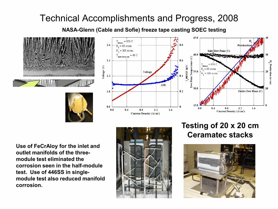
Technical Accomplishments and Progress, 2008
Testing of 20 x 20 cm Ceramatec stacks
NASA-Glenn (Cable and Sofie) freeze tape casting SOEC testing
Use of FeCrAloy for the inlet and outlet manifolds of the three-module test eliminated the corrosion seen in the half-module test. Use of 446SS in single-module test also reduced manifold corrosion.

Immediate Challenge: Long-term Cell Degradation
0
500
1000
1500
2000
2500
3000
3500
4000
0 200 400 600 800 1000
based on currentbased on dewpoints
hydr
ogen
pro
duct
ion
rate
(scc
m)
time, hours
increased stack temperature from 800 to 830 C
210
hydrogen production rate, NL/hr
180
150
120
90
60
30
0
240
Cell increases in resistance while operating at constant voltage,leading to a decrease in H2 production.
Possible causes:• Chromium transport to electrodes from interconnects• Silicon transport to electrodes from sealants• Changes in electrolyte morphology due to transport of yttria or scandia• Delamination due to limited O2 formation at the electrolyte-electrode interface
Jan-Feb 2006 25-cell test:rate: 21%/1000 hours ILS Three Module Operation
Sept-Oct 2008At 480 hrs the H2 recycle was fixed

• Cation interdiffusion between cathode and electrolyte of SOFCs
• Presence of Cr-containing species in SOFC cathode
Investigation of degradation mechanisms in SOEC Oxygen electrodes
Bond Layer Dissociation
Cation segregation Local variations in cation ratios at catalyst surface
Interdiffusion of Cr-containing species from interconnects into bond layer and anode
Cr distribution across the bond layer and anode
Relationship between Cr and
local composition
Cr-Mn Spinel
Degradation studies roadmap
Testing of fully stabilized ScSz and YSZ electrolyte performance
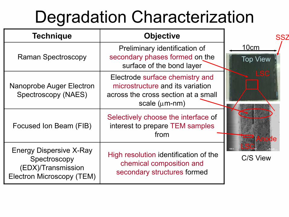
Degradation CharacterizationTechnique Objective
Raman SpectroscopyPreliminary identification of
secondary phases formed on the surface of the bond layer
Nanoprobe Auger Electron Spectroscopy (NAES)
Electrode surface chemistry and microstructure and its variation
across the cross section at a small scale (μm-nm)
Focused Ion Beam (FIB)Selectively choose the interface of interest to prepare TEM samples
from
Energy Dispersive X-Ray Spectroscopy
(EDX)/Transmission Electron Microscopy (TEM)
High resolution identification of the chemical composition and
secondary structures formed
LSCAnode
LSC
SSZ
Top View
C/S View
10cm

12
Collaborations• INL Sponsored International Workshop on Degradation, October
2008, with 25 experts on SOFC and SOEC degradation mechanisms. Using output of workshop to guide further development and testing
• Ceramatec, Inc., Salt Lake City: development and manufacture of electrolyte-supported cells used in the Integrated Laboratory Scale experiments in 2007 and 2008
• MIT: analysis of cells to determine causes of degradation, particularly of oxygen electrode
• Argonne National Laboratory: post-test analysis of cells• Virginia Tech: development and analysis of sealant glasses (NERI)• Georgia Tech: development of porosity-gradient oxygen electrodes
(NERI)• University of Arizona: summer student• NASA-Glenn: testing of all-ceramic stack concept• MSRI, VersaPower and St. Gobain: testing of their hydrogen-
electrode-supported SOFC designs in electrolytic mode
Future work for FY-09
Emphasis: Improve long-term SOEC performance
•Finish expansion of INL testing lab to allow parallel testing of up to five experiments • allowing for accelerated studies of degradation
• Participate in Karlsruhe (EIFER) workshop on HTSE degradation. June ‘09• Conduct tests on button cells and stacks during FY-09 of various designs from
various vendors (MSRI, St. Gobain, VersaPower, NASA,..)• Ceramatec: Transition to use of a fully stabilized scandia-zirconia electrolyte• Ceramatec: Explore advanced electrode materials• Examine cells using Auger and Raman spectroscopy
determine elemental transport and changes in morphology• Collaborate with SECA SOFC manufacturers to determine why SOFC degradation
rates are ~10x lower• Experimentally adjust average steam concentration within cells to determine if drier
gas conditions (~SOFC conditions) result in slower degradation• Experiment with coatings on the interconnect to prevent Cr transport

Future work for FY-10
Major assumption: HTSE is chosen to go forward for development with the NGNP
Design of pilot plantPressurized operation - will require development work Experimental and computation efforts Develop heat integration with the NGNPFlowsheet analysisDevelopment of heat exchangersInitiate down-selection of potential SOEC vendorsContinue improvement of long-term SOEC performanceContinue study of SOEC for synthesis of liquid fuels as well as for production of hydrogen for end-use needs
15
• Constructed and operated the Integrated Laboratory Scale experiment with a full set of modules for 1080 hrs in Sept.-Oct. 2008– Automated, integrated platform; unattended operation– Heat recuperation– Hydrogen recycle– Little corrosion of manifolds (new manifold material)
• Major issue with the degradation of cells – possible causes:– Chromium transport to electrodes from interconnects– Silicon transport to electrodes from sealants– Changes in electrolyte morphology due to transport of yttria or scandia– Delamination due to limited O2 formation at the electrolyte-electrode interface
• Focus in FY-09– Long-term short stack and button-cell testing– Testing of cells from additional manufacturers– Detailed characterization of processes in electrolytic cells
• Nanoscale Auger and Raman scans of electrodes and electrolyte • Sectioning at the interfaces to determine migration
Summary