HIGH TEMPERATURE CLEARANCE - Pentair Thermal BLADES IN AN OPERATIONAL TURBINE, EVEN AT HIGH...
16
HIGH TEMPERATURE CLEARANCE AND VIBRATION MONITORING SYSTEMS THERMAL MANAGEMENT SOLUTIONS WWW.CAPACISENSE.COM
Transcript of HIGH TEMPERATURE CLEARANCE - Pentair Thermal BLADES IN AN OPERATIONAL TURBINE, EVEN AT HIGH...

HIGH TEMPERATURE CLEARANCEAND VIBRATION MONITORING SYSTEMSTHERMAL MANAGEMENT SOLUTIONS WWW.CAPACISENSE.COM
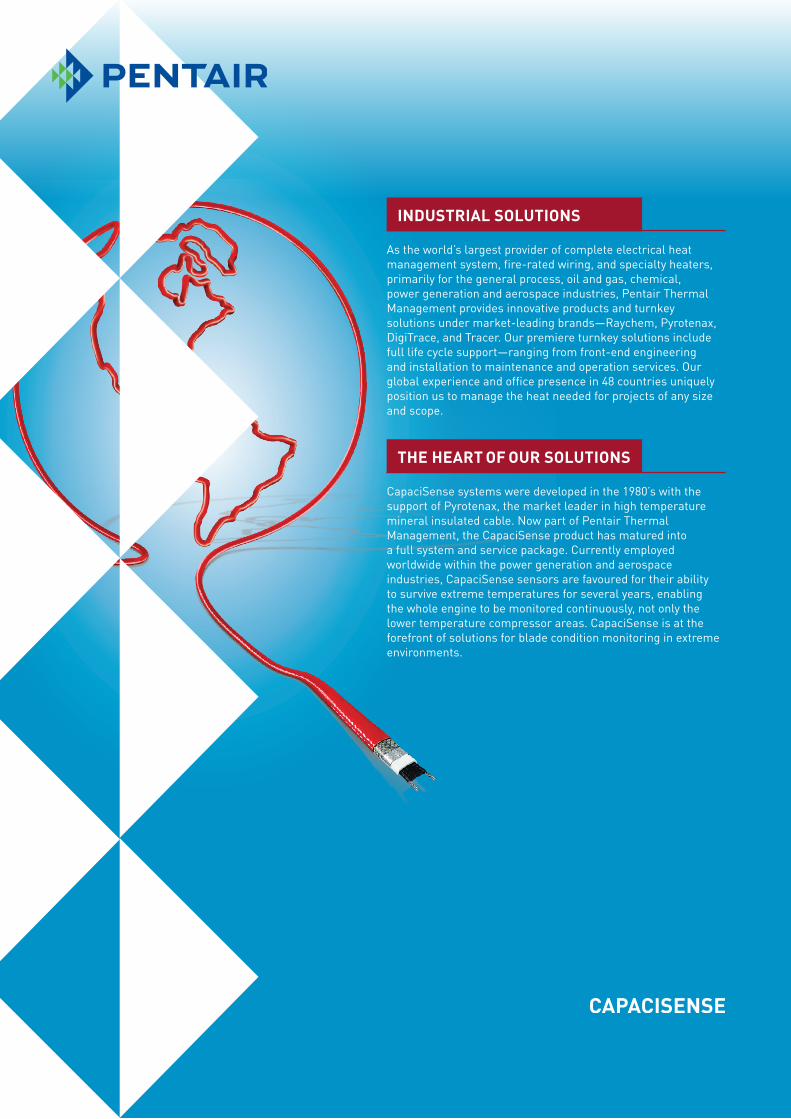
INDUSTRIAL SOLUTIONS
THE HEART OF OUR SOLUTIONS
As the world’s largest provider of complete electrical heat management system, fire-rated wiring, and specialty heaters, primarily for the general process, oil and gas, chemical, power generation and aerospace industries, Pentair Thermal Management provides innovative products and turnkey solutions under market-leading brands—Raychem, Pyrotenax, DigiTrace, and Tracer. Our premiere turnkey solutions include full life cycle support—ranging from front-end engineering and installation to maintenance and operation services. Our global experience and office presence in 48 countries uniquely position us to manage the heat needed for projects of any size and scope.
CapaciSense systems were developed in the 1980’s with the support of Pyrotenax, the market leader in high temperature mineral insulated cable. Now part of Pentair Thermal Management, the CapaciSense product has matured into a full system and service package. Currently employed worldwide within the power generation and aerospace industries, CapaciSense sensors are favoured for their ability to survive extreme temperatures for several years, enabling the whole engine to be monitored continuously, not only the lower temperature compressor areas. CapaciSense is at the forefront of solutions for blade condition monitoring in extreme environments.

MONITOR BLADES IN AN OPERATIONAL TURBINE, EVEN AT HIGH TEMPERATURESCapaciSense systems combine blade tip clearance and vibration monitoring using high bandwidth electronics to provide two sets of data from one state-of-the-art turbine sensor. With sensors (probes) that are able to withstand temperatures of 1400°C/2550°F, CapaciSense systems enable you to monitor at turbine temperatures in continuous operation.
By providing a virtual window to see inside your operating turbine engine, CapaciSense condition monitoring systems:
• Provide accurate real-time data to help you achieve smaller clearances, optimising the machine’s efficiency, therefore, cutting down fuel costs
• Monitor differential thermal growth during warm restarts to prevent tip damage caused by blade rubbing
• Monitor vibrations through tip timing to provide an early warning of problems or potential failure, preventing unplanned and expensive outages or even catastrophic failure
CapaciSense systems are used in gas turbines within the power generation and aerospace industries, although they are also suitable for other applications where a conventional proximity probe would not survive the environment.
CapaciSense systems are based on capacitance theory and contain sensors, turbine mounted/local electronics, remote electronics and a control and processing module with software.
This document gives a brief overview of what CapaciSense has to offer. Contact your local representative to discuss your needs.
1FLOORHEATING 1HIGH TEMPERATURE CLEARANCE AND VIBRATION MONITORING SYSTEMS

BACKGROUND INFORMATION
CapaciSense systems were developed in the 1980’s with the support of Pyrotenax, the market leader in high temperature mineral insulated cable. Now part of Pentair Thermal Management, the CapaciSense product has matured into a full system and service package. Currently employed worldwide within the power generation and aerospace industries, CapaciSense sensors are favoured for their ability to survive extreme temperatures for several years, enabling the whole engine to be monitored continuously, not only the lower temperature compressor areas.
CapaciSense is at the forefront of solutions for blade condition monitoring in extreme environments.
KEY DEVELOPMENTS AND MILESTONES1988 First triax cable for capacitive sensors supplied
1996 First development sensor design
1997 Sensor patent granted
2003 First sensors into production engines
2006 CapaciSense brand launched, 150th sensor designed
2006 Industrialised ATEX and FM approved systems
2007 First retrofit installation and 5 Series demodulator launched
2008 5 Series oscillator launched
2009 5 Series ATEX approval and blade clearance and vibration software launch
2010 5 Series FM approval
2 PENTAIR2 THERMAL MANAGEMENT SOLUTIONS

APPLICATIONS
ENGINE DESIGN VERIFICATION
OPERATING ENGINE
RETROFIT
NON-GAS TURBINES
A driving factor when designing gas turbines, whether it be power generation or aerospace, is their fuel efficiency. Higher fuel efficiency means lower operating costs, often driving the decision on which turbine to adopt. Most of the world’s leading developers of power generation turbines have used our systems for design verification of blade tip to shroud clearances at high temperatures, supplanting the older technologies.
By using our CapaciSense system, turbine designers can get a live picture of the blade tip clearances in prototype engines during all phases of the engine’s operation.
Designers of some of the world’s largest power generating turbines are now choosing to install our condition monitoring system to continuously monitor blade clearances and vibration. Our system offers data for informed user control of adaptive clearance systems.
As downtime for maintenance is expensive, it is imperative that this is minimised and performed at the right time with informed knowledge of current engine conditions. By retrofitting with a CapaciSense system, the operator can be given forward notice of potential blade failure due to blade rubbing or vibration. This additional intelligence on the engine operation allows warm restarts to be safely performed with the knowledge that differential thermal expansion isn’t going to cause a blade rub which will result in costly repairs.
With approvals including ATEX and FM, our systems can be used safely in hazardous areas. This is of particular interest for those considering retrofitting turbines with additional condition monitoring sensors for predictive maintenance or to check blades in “near rubbing” conditions.
While CapaciSense system’s primary application is in gas turbines, it can be used for proximity applications where conventional systems are inadequate, for example gas seal clearances or piston clearance measurement.
3FLOORHEATING 3HIGH TEMPERATURE CLEARANCE AND VIBRATION MONITORING SYSTEMS

WHY CHOOSE A CAPACISENSE SYSTEM?
IMPROVED RELIABILITY AND REDUCED MAINTENANCE COSTS
SUITABLE FOR HAZARDOUS LOCATIONS
IMPROVED OUTPUT AND EFFICIENCY
By providing real time data, you will access early warning signals of potential problems, which will help you to make decisions and avoid unplanned and expensive outages or even catastrophic failure.
Turbines are extremely sensitive to blade tip rubbing, which can be the cause of failure. Our tip clearance functionality will monitor differential thermal growth during warm restarts, and the information provided helps you to prevent tip damage caused by blade rubbing.
Our tip timing functionality will monitor the arrival time of a blade tip and use this to calculate blade deflections and identify vibration.
With ATEX and FM approval, our fully industrialised systems are suitable for use in hazardous locations.
The engine mounted FM oscillator enclosure is ATEX and FM approved, allowing intrinsically safe operation when systems are used for condition monitoring of running engines. Nonhazardous area enclosures are also available for occasions when the oscillators are to be mounted outside of turbine compartment using sensor cable lengths of up to 10 m (32.8 ft).
Due to the high temperatures our sensors can sustain 1400°C/2552°F, even the turbine stage blade clearance can be measured, an important factor as this means the whole engine can be monitored, not just the lower temperature compressor areas. This raises the possibility of controlling the various stages differentially and optimising the whole turbine rather than just one zone.
As the turbine’s fuel efficiency is directly affected by the size of the clearance, designers and manufacturers are using the live outputs to adjust clearances to a minimum on working turbines and therefore gaining greater fuel efficiencies.
4 PENTAIR4 THERMAL MANAGEMENT SOLUTIONS

TIP TIMING AND CLEARANCE FROM ONE SENSOR
For condition monitoring applications, sensors need to perform well over extended periods of time. CapaciSense sensors are proved to be robust. The four sensors pictured to the right have had years in the hottest turbine zone in one of the world’s largest turbines. They were removed during regular servicing and are still functional. One sensor has been polished to remove combustion product deposits—it shows it is still close to its original condition. All CapaciSense sensors have patented fully captive components which limits the risk of the sensor breaking apart into the engine—even if it is damaged.
Our systems have been successfully used worldwide by gas turbine manufacturers to verify the frame clearances in extreme environments for many years.
The CapaciSense team provides a full design and development service on every project in order to meet the requirements of your application. We custom make our sensors to suit your environment:
• Extremes of temperature (>1400°C/2250°F)
• Temperature cycling
• Vibration
• Moisture (including on-line water wash)
Calibration disc design and manufacture to replicate actual blade tip profiles, sensor calibration and a full installation service are offered as part of our solution. It is our goal not to provide components but to provide the whole solution.
CapaciSense systems can provide both tip clearance and tip timing from one state-of-the-art sensor. With the advent of the new high speed 5 Series electronics and software, the blade passing signal, which has traditionally provided only clearance information is now capable of resolving blade time of arrival. Traditional methods for measuring blade fatigue include strain gauging and optical tip timing. Whilst strain gauges provide accurate information, they only provide that information for the blades which are instrumented and these gauges are not suitable for a production environment.
Optical sensors provide excellent tip timing data but only for short periods of time before their optics became fogged with contamination. By using already proven CapaciSense clearance sensors, additional data can be derived on blade vibration without the need to install additional instrumentation.
LONG LASTING
TRUSTED HISTORY
CUSTOMISED SOLUTIONS
5FLOORHEATING 5HIGH TEMPERATURE CLEARANCE AND VIBRATION MONITORING SYSTEMS
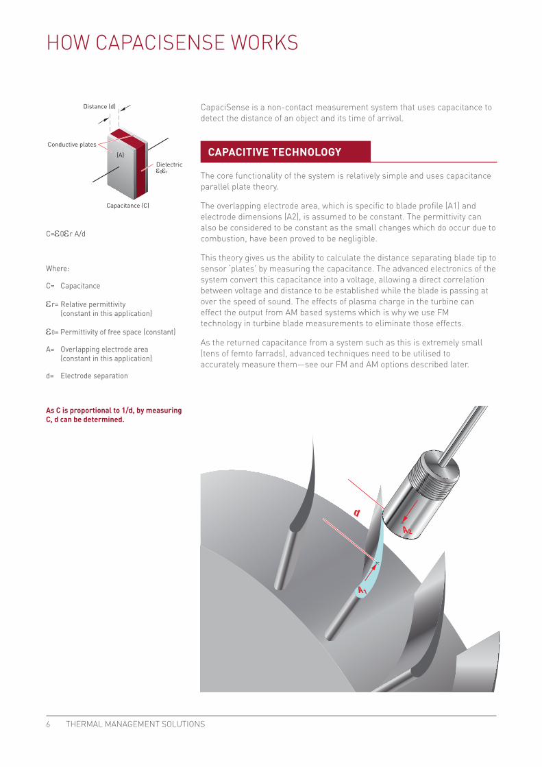
C=e0er A/d
Where:
C= Capacitance
er= Relative permittivity (constant in this application)
e0= Permittivity of free space (constant)
A= Overlapping electrode area (constant in this application)
d= Electrode separation
As C is proportional to 1/d, by measuring C, d can be determined.
Conductive plates
Distance (d)
Capacitance (C)
Dielectric(A)
ε0εr
A 2
A 1
d
HOW CAPACISENSE WORKS
CapaciSense is a non-contact measurement system that uses capacitance to detect the distance of an object and its time of arrival.
The core functionality of the system is relatively simple and uses capacitance parallel plate theory.
The overlapping electrode area, which is specific to blade profile (A1) and electrode dimensions (A2), is assumed to be constant. The permittivity can also be considered to be constant as the small changes which do occur due to combustion, have been proved to be negligible.
This theory gives us the ability to calculate the distance separating blade tip to sensor ‘plates’ by measuring the capacitance. The advanced electronics of the system convert this capacitance into a voltage, allowing a direct correlation between voltage and distance to be established while the blade is passing at over the speed of sound. The effects of plasma charge in the turbine can effect the output from AM based systems which is why we use FM technology in turbine blade measurements to eliminate those effects.
As the returned capacitance from a system such as this is extremely small (tens of femto farrads), advanced techniques need to be utilised to accurately measure them—see our FM and AM options described later.
CAPACITIVE TECHNOLOGY
6 PENTAIR6 THERMAL MANAGEMENT SOLUTIONS

Blade passing signal output showing how measuring pulse amplitude is used for clearance monitoring
Blade passing signal output showing how measuring time of arrival is used for vibration monitoring
Reduced clearance
Clearance
Engine casingSensor
Blades
Engine casing
Blades
Sensor
Vibrating blade
Bladetiming
TIP CLEARANCE
TIP TIMING
7FLOORHEATING 7HIGH TEMPERATURE CLEARANCE AND VIBRATION MONITORING SYSTEMS

APPROVALS AND CERTIFICATIONS
CapaciSense high temperature clearance and vibration monitoring systems are approved and certified for use in nonhazardous and haz-ardous locations by FM Approvals and Baseefa.
An FM (frequency modulated) system is chosen to monitor intermittent signals from blades. The system works on the principal of measuring the capacitance change between the sensor electrode and a passing blade. This blade to sensor tip capacitance change forms part of a tuned oscillating circuit.
Changes in capacitance at the sensor tip due to the passing blades cause a frequency modulation of the 2 MHz carrier signal. This change is demodulated to a change in output voltage each time a blade passes the sensor tip. Due to the high and low speed capabilities of the 5 Series electronics, they can operate on engines with blade passing events from around 10 Hz to 50 Hz and with a blade passing time, leading edge to trailing edge, of approximately 4ųs.
The two main factors which govern changes in sensor tip capacitance are the sensor/blade tip geometry and blade tip clearance. During operation the sensor/blade tip geometry usually remains constant; therefore any changes in capacitance at the sensor tip are the direct result of variations in tip clearance.
Use of frequency modulation makes the system sensitive to carrier frequency variations and ignores ESD (Electro Static Discharge) or EM (Electro Magnetic) varying fields. The FM system also operates via a low carrier voltage making it ideal for hazardous area application, unlike some high voltage systems available. The oscillator electronics are designed to minimise and compensate for cable and sensor capacitance variations which may change as the ambient temperature surrounding the sensor increases to 1400°C/2552°F.
Backed by more than fifty years of mineral cable expertise, our triaxial cables provides reliable, low noise signals in the harsh operating environment of a gas turbine. With over 175 bespoke sensor designs manufactured and in operation, the FM system provides a turnkey solution for condition monitoring.
5 SERIES FM SYSTEM
8 PENTAIR8 THERMAL MANAGEMENT SOLUTIONS
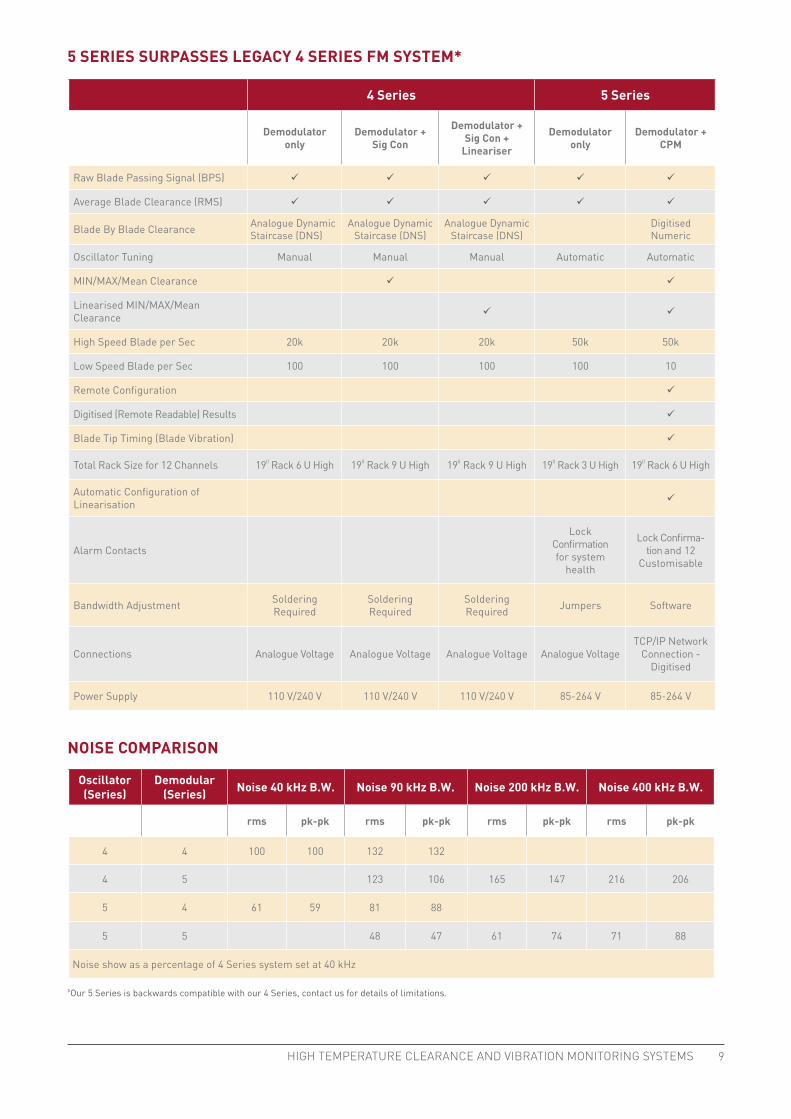
4 Series 5 Series
Demodulator only
Demodulator + Sig Con
Demodulator + Sig Con +
Lineariser
Demodulator only
Demodulator + CPM
Raw Blade Passing Signal (BPS) ü ü ü ü ü
Average Blade Clearance (RMS) ü ü ü ü ü
Blade By Blade Clearance Analogue Dynamic Staircase (DNS)
Analogue Dynamic Staircase (DNS)
Analogue Dynamic Staircase (DNS)
Digitised Numeric
Oscillator Tuning Manual Manual Manual Automatic Automatic
MIN/MAX/Mean Clearance ü ü
Linearised MIN/MAX/Mean Clearance ü ü
High Speed Blade per Sec 20k 20k 20k 50k 50k
Low Speed Blade per Sec 100 100 100 100 10
Remote Configuration ü
Digitised (Remote Readable) Results ü
Blade Tip Timing (Blade Vibration) ü
Total Rack Size for 12 Channels 19II Rack 6 U High 19II Rack 9 U High 19II Rack 9 U High 19II Rack 3 U High 19II Rack 6 U High
Automatic Configuration of Linearisation ü
Alarm Contacts
Lock Confirmation for system
health
Lock Confirma-tion and 12
Customisable
Bandwidth Adjustment Soldering Required
Soldering Required
Soldering Required Jumpers Software
Connections Analogue Voltage Analogue Voltage Analogue Voltage Analogue VoltageTCP/IP Network
Connection - Digitised
Power Supply 110 V/240 V 110 V/240 V 110 V/240 V 85-264 V 85-264 V
Oscillator(Series)
Demodular(Series) Noise 40 kHz B.W. Noise 90 kHz B.W. Noise 200 kHz B.W. Noise 400 kHz B.W.
rms pk-pk rms pk-pk rms pk-pk rms pk-pk
4 4 100 100 132 132
4 5 123 106 165 147 216 206
5 4 61 59 81 88
5 5 48 47 61 74 71 88
Noise show as a percentage of 4 Series system set at 40 kHz
NOISE COMPARISON
5 SERIES SURPASSES LEGACY 4 SERIES FM SYSTEM*
ÞOur 5 Series is backwards compatible with our 4 Series, contact us for details of limitations.
9FLOORHEATING 9HIGH TEMPERATURE CLEARANCE AND VIBRATION MONITORING SYSTEMS

Oscillators
10 m(32.8 ft)
limit
100 m(328 ft)
limit
CPM
Remotenetwork access
Demodulators
Sensors
SENSOR AND CABLE ASSEMBLY
The sensors are of triaxial construction
• Centre electrode (induced – modified by target)
• Inner guard (driven)
• Outer screen/body (noise reduction)
• All inner components are captive on all temperature designs
Super-alloys are employed to reach tip temperatures of 1400°C/2552°F. All sensors are custom designed.
5 SERIES FM SYSTEM COMPONENTS
10 PENTAIR10 THERMAL MANAGEMENT SOLUTIONS

The oscillator drives the sensor with a 2 MHz oscillating carrier frequency (typically), the control circuit is then used to keep this constant and compensate for changes in temperature. Changes in capacitance at the sensor tip modulate this frequency. This modulation is then translated into an output voltage by the demodulator. The 5 Series also features an onboard memory which stores calibration. This eliminates human error at installation by removing the need to manually enter calibration data. Oscillators are usually engine mounted in a cooled enclosure or mounted externally with a 10 m (32.8 ft) cable.
The demodulator extracts the frequency changes from the oscillator and converts this to a voltage. This voltage is proportional to changes in capacitance at the sensor tip. Using the calibration data, this voltage can be used to determine the clearance. CapaciSense systems have a bandwidth of 400 kHz, giving a high resolution to our blade vibration measurements.
Used initially to configure the system and to present the data in values, figures and visual plots and charts:
• Up to 10 MHz simultaneous sampling in control and processing modules (CPM) from analogue BPS signal
• Built-in data acquisition and software means no analogue data for the user to acquire and analyse
• Gain and bandwidth settings (90/200/400 kHz) controlled via CPM
• Auto download of sensor calibration means you can never mix your signals
• Auto setup—no jumper settings
• Sync signal—used to synchronise multipleracks for the pooling of data
• Hard disc for data storage and further analysis
• 5 Series oscillator will allow Ultra Slow Mode
• Once per rev input (engine speed/blade identification)
• Configurable alarm volt-free contacts for basic remote monitoring
• Addition of blade vibration monitoring from the same system that gives you the tip clearance (simple software update)
• Smaller footprint—12 (5 Series) channels in the space of 8 (4 Series), remote access from Microsoft Windows® or Linux® based machines—no software needs to be installed.
CONTROL AND PROCESSING MODULE WITH SOFTWARE
OSCILLATOR
DEMODULATOR
High Temperature Sensors
Used predominantly for turbine applications. The inclusion of flutes and cooling apertures has advanced the operational capabilities of these designs over to 1400°C/2552°F, allowing several years of operation.
Mid Range Temperature Sensors
Typically for FM compressor applications or AM systems, the mid temperature range of designs have an operating temperature of up to 1000°C/1832°F. The sensors have the same characteristics as the high temperature range without the cooling functionality. These sensors can be used at higher temperatures although their life will be shortened.
Lower Temperature Sensors
For operational use at tempera-tures below 200°C/392°F, the low temperature design incorporates flexible triaxial cable as opposed to mineral insulated cable. Whilst still using the specialist assembly techniques, the sensors benefit from a lower cost and easierinstallation.
11FLOORHEATING 11HIGH TEMPERATURE CLEARANCE AND VIBRATION MONITORING SYSTEMS
AM SYSTEM
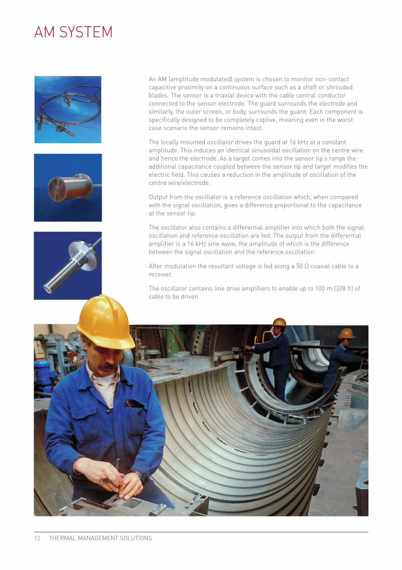
An AM (amplitude modulated) system is chosen to monitor non-contact capacitive proximity on a continuous surface such as a shaft or shrouded blades. The sensor is a triaxial device with the cable central conductor connected to the sensor electrode. The guard surrounds the electrode and similarly, the outer screen, or body, surrounds the guard. Each component is specifically designed to be completely captive, meaning even in the worst case scenario the sensor remains intact.
The locally mounted oscillator drives the guard at 16 kHz at a constant amplitude. This induces an identical sinusoidal oscillation on the centre wire and hence the electrode. As a target comes into the sensor tip’s range the additional capacitance coupled between the sensor tip and target modifies the electric field. This causes a reduction in the amplitude of oscillation of the centre wire/electrode.
Output from the oscillator is a reference oscillation which, when compared with the signal oscillation, gives a difference proportional to the capacitance at the sensor tip.
The oscillator also contains a differential amplifier into which both the signal oscillation and reference oscillation are fed. The output from the differential amplifier is a 16 kHz sine wave, the amplitude of which is the difference between the signal oscillation and the reference oscillation.
After modulation the resultant voltage is fed along a 50 Ω coaxial cable to a receiver.
The oscillator contains line drive amplifiers to enable up to 100 m (328 ft) of cable to be driven.
12 PENTAIR12 THERMAL MANAGEMENT SOLUTIONS
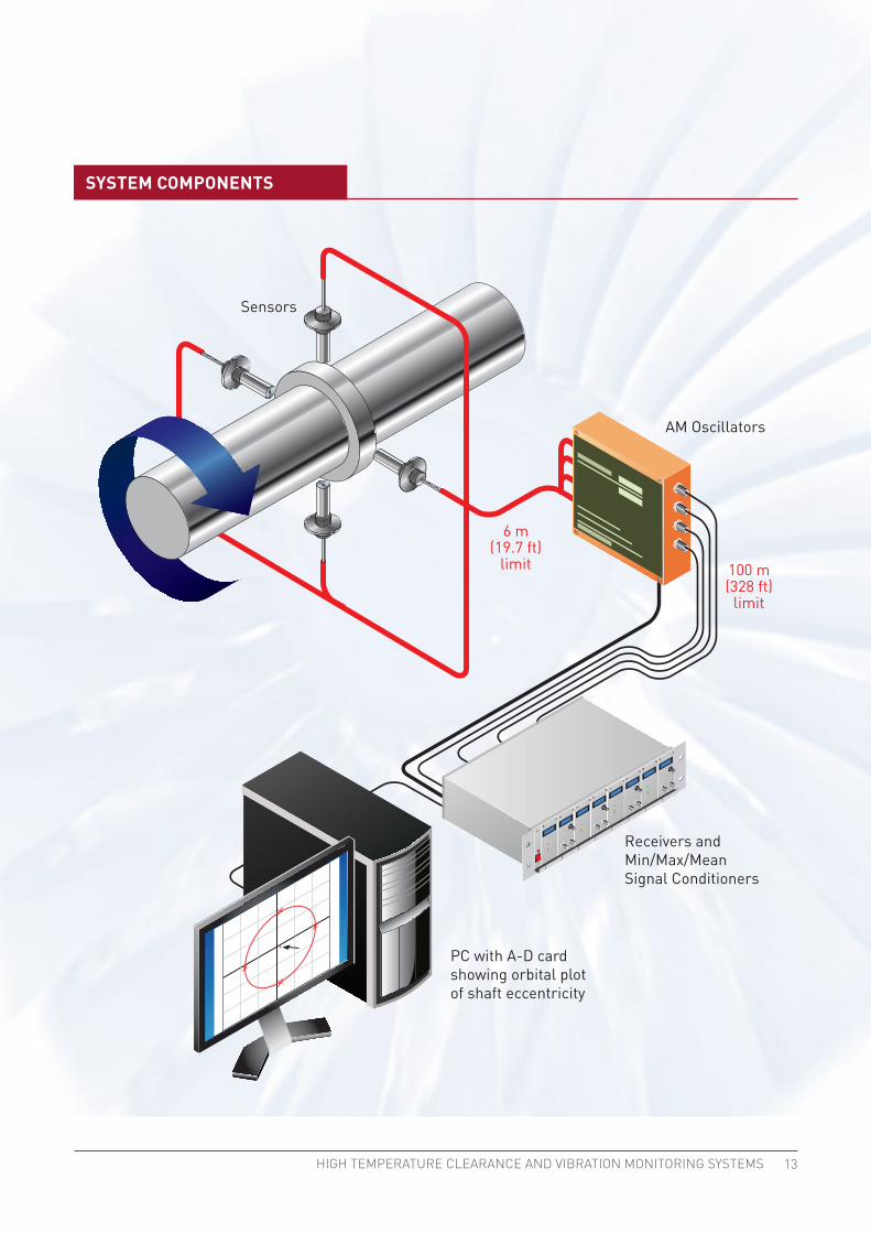
6 m(19.7 ft)
limit 100 m(328 ft)
limit
Receivers and Min/Max/Mean Signal Conditioners
PC with A-D cardshowing orbital plotof shaft eccentricity
Sensors
AM Oscillators
SYSTEM COMPONENTS
13FLOORHEATING 13HIGH TEMPERATURE CLEARANCE AND VIBRATION MONITORING SYSTEMS

GB-CapaciSenseHighTemperatureClearanceNAM-SB-H58659 01/13 THERMAL MANAGEMENT SOLUTIONS
WORLDWIDE HEADQUARTERS 7433 Harwin DriveHouston, TX 77036 Tel: +1.800.545.6258Fax: +1.800.527.5703Tel: +1.650.216.1526Fax: [email protected]
LATIN AMERICA7433 Harwin DriveHouston, TX 77036Tel: 713-868-4800 Tel: 713-735-8645Fax: 713868-2333
JAPAN4F KC Bldg. 3-16-1Shin-Yokohama, Kohoku-kuYokohama, Kanagawa, 222-0033JapanTel: +81 45 471 7630Fax: +81 45 471 7631
UNITED KINGDOM3 Rutherford RoadStephenson Industrial EstateWashington, Tyne & WearNE37 3HX, United KingdomTel: +44 191 4198200Fax: +44 191 4198201 www.capacisense.com
Pentair, CapaciSense, Pyrotenax, Tracer, DigiTrace and TraceTek are owned by Pentair or its global affiliates. All other trademarks are the property of their respective owners. Pentair reserves the right to change specifications without prior notice.
© 2010-2013 Pentair.
WWW.THERMAL.PENTAIR.COM