High T Superconducting Applications in Geophysical ... sessions/17am...c Superconducting...
68
High T c Superconducting Applications in Geophysical Exploration and Telecommunications MANUFACTURING and DATA61 C.P. Foley CSIRO Team: Jia Du, Keith Leslie, Emma Mitchell, Shane Keenan, Kirsty Hannam, Jeina Lazar, Chris Lewis, Bill Vasilevski, Karl Wilson, Andrew Weily, Xiang Gao, Ting Zhang, Wendy Purches, Alex Gracea, Kyle Blay
Transcript of High T Superconducting Applications in Geophysical ... sessions/17am...c Superconducting...

High Tc Superconducting Applications in Geophysical Exploration and Telecommunications
MANUFACTURING and DATA61
C.P. Foley
CSIRO Team: Jia Du, Keith Leslie, Emma Mitchell, Shane Keenan, Kirsty Hannam, Jeina Lazar, Chris Lewis, Bill Vasilevski, Karl Wilson, Andrew Weily, Xiang Gao, Ting Zhang, Wendy Purches, Alex Gracea, Kyle Blay

Relationship of Geophysical Exploration
and Communications
USA Population: 0.3B
Australian Population: 0.02B
Australia has the same
population as Shanghai


Presentation title | Presenter name | Page 4

Communication across vast distances to small populations
5 |


This talk
• Josephson junctions in HTS – recent emergence of step edges
• Geophysical applications• Magnetometers
• Gradiometers
• High frequency devices
• New concept antennas
7 |


YBCO is not an easy material
Nature Materials 6, 631 - 642 (2007) S. R. Foltyn, L. Civale, J. L. MacManus-Driscoll, Q. X. Jia, B. Maiorov, H. Wang & M. Maley
• Highly anisotropic
• a-b coherence length ≈ 2 nm
• One element is a gas

1 µm
1 µm


| Dimos et al Phys Rev B 1990 41 4038

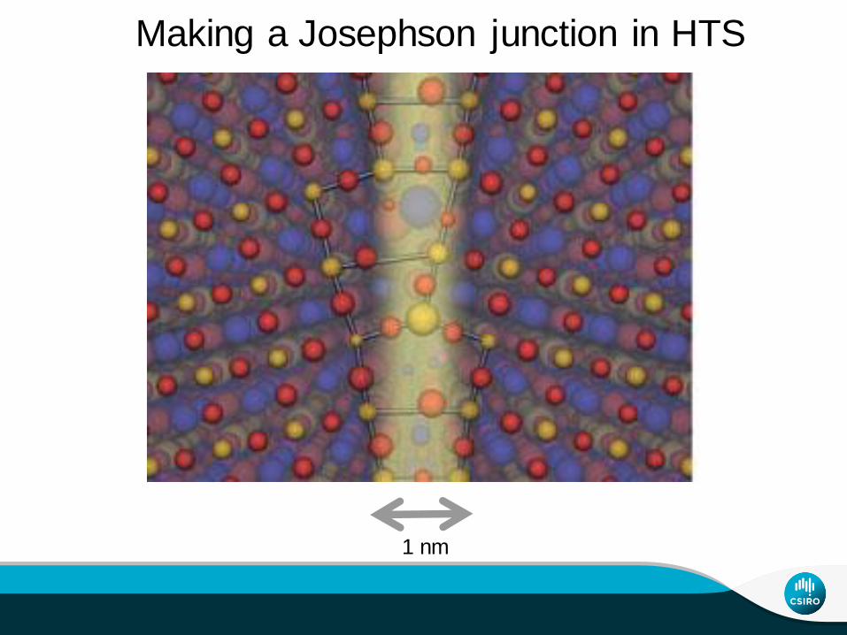
1 nm
Making a Josephson junction in HTS

Enpuku and Minotani Simplistic Model IEICE Trans Electron E83-C (2000) 34
SuperconductorSuperconductor Insulator
Cooper Pair Direct tunnel (d-wave symmetry)
Direct tunnel
Resonant tunnel
Trap and escape (1/f noise)
Quasiparticles

| Fagaly Review of Scientific Instruments (2006) 77 101101
Bicrystal and ion beam damaged
Step edgeRamp
Important parameters:
- IcRn – aim for 1000 µV
- Critical current fluctuations with B
- Ic control <9% spread

Bicrystal Junctions
IcRn product of symmetric 20o bicrystal junctions ∼400 μV at 77.4 K

Ramp Junctions
|
Moeckly and Char APL 1997 71 2526
Wen et al Applied Physics Letters 75, 2470 (1999)
IcRn at 77 K 156 µV

Step edge grain boundary junctions
|

STO
MgO
c axis
c axis
Why MgO?
LAO
“Step-edge Josephson junctions and SQUIDs” F. Lombardi and A. Ya. Tzalenchuk
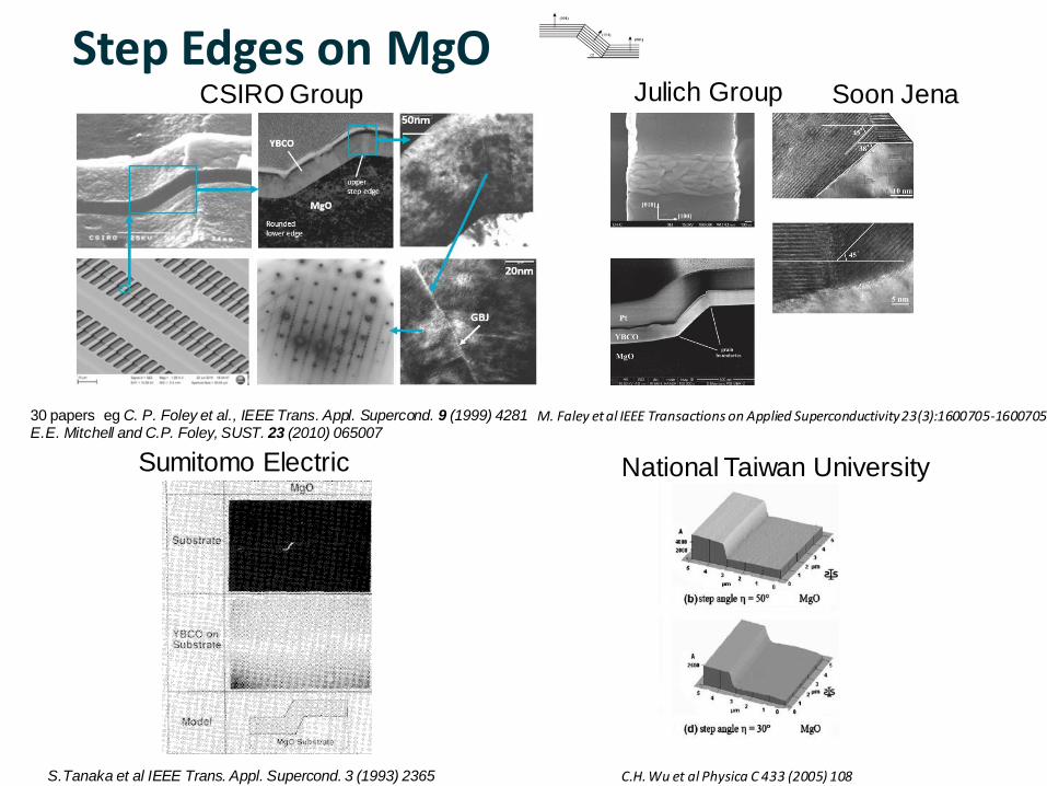
Step Edges on MgOJulich Group
M. Faley et al IEEE Transactions on Applied Superconductivity 23(3):1600705-1600705
CSIRO Group
30 papers eg C. P. Foley et al., IEEE Trans. Appl. Supercond. 9 (1999) 4281E.E. Mitchell and C.P. Foley, SUST. 23 (2010) 065007
S.Tanaka et al IEEE Trans. Appl. Supercond. 3 (1993) 2365
Sumitomo Electric National Taiwan University
C.H. Wu et al Physica C 433 (2005) 108
Soon Jena

Can you do over the edge but not come back up?
“Escher steps”

Development of a step edge Josephson junction
24 |
First efforts


Presentation title | Presenter name | Page 26

CSIRO HTS Step-edge Josephson Junction technology - many HTS electronic devices built upon
1m
Θ= 36.8±0.2o
YBCO film
C. P. Foley et al, IEEE Trans. Appl. Supercond. 9 1(999) 4281.E.E. Mitchell and C.P. Foley, Supercond. Sci. Technol. 23 (2010) 065007

Junction noise in a magnetic shield
0
1
2
3
0.4 0.6 0.8 1.0
cath1.ep
BC2 bi-xtal
ML384Pk.1Pk.2
ML789Pk.2 Pk.1
ML635
T/Tc
Sv (
nV
Hz
-1/2
)VOLTAGE NOISE vs. REDUCED TEMPERATURE FOR
3 STEP-EDGE JUNCTIONS (ML***) AND 1 BI-XTAL JUNCTION
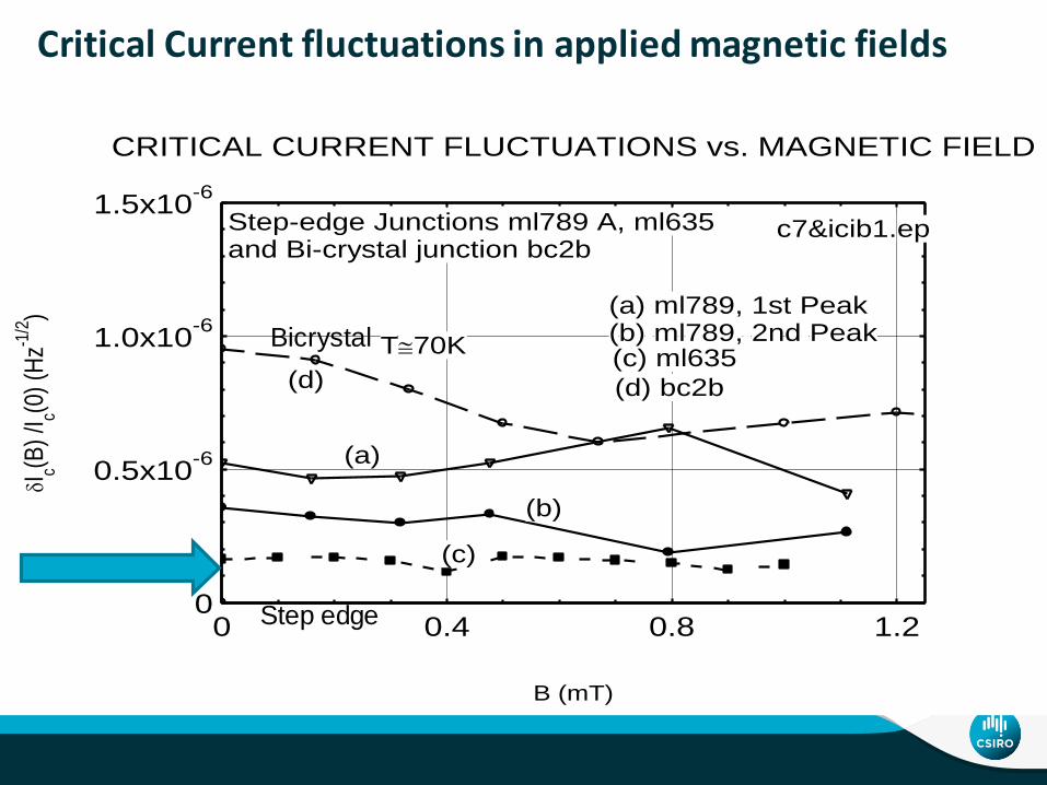
0
0.5x10⁻⁶
1.0x10⁻⁶
1.5x10⁻⁶
0 0.4 0.8 1.2
(d) bc2b(d)
(c)
(c) ml635T70K
Step-edge Junctions ml789 A, ml635and Bi-crystal junction bc2b
c7&icib1.ep
(a) ml789, 1st Peak(b) ml789, 2nd Peak
(b)
(a)
B (mT)
Ic(B
) /I c(0
) (H
z-1/2
)
CRITICAL CURRENT FLUCTUATIONS vs. MAGNETIC FIELD
Critical Current fluctuations in applied magnetic fields
Bicrystal
Step edge

Lindfield Clean Room – HTS FoundaryDesign rules available

Geophysical ExplorationApplicationsMagnetometer – Active TEM

RF SQUID - 1 junction
|
X

conductorDecaying eddy current
Transient Electromagnetics (TEM)

1992-1993
First HTS Ground-based TEM system
BHPB
1994-1997
“Airborne System”
BHPB1999-2001
Prototype unit
Falconbridge/Crone2002-2004
LANDTEMTM
Outer-Rim Exploration Services
RF SQUID LANDTEMTM system

35 |

2 Junction: HTS DC SQUIDs
Field noise ~ 30 fT/root Hz (white)
Flux noise ~ 5 /root Hz

HTS Gradiometers
37 / 20

Gradiometers Systems using High Tc Junctions
Rotating axial gradiometersSensitivity – 10 pT/m/Hz at 10 Hz unshielded need 3
Static planar gradiometers (hexagonal-prism)Sensitivity – 2 pT/m/Hz at 10 Hz unshielded need 6
Rotating planar gradiometer-initial results; continuing improvement – need 1!Sensitivity ~ 50 pT /(m.√Hz) in rotation at 2nd harmonic (30 Hz) Stable operation in Earth’s field
1. 2. 3.
z
yx

Rotating the Axial Gradiometer.
• Fourier transform of signals from three rotating gradiometers provides information to derive all the components of the magnetic field gradient tensor and magnetic field vectors, providing information about the bearing and range to the target
• Common Mode Rejection of Earth’s field achieved by frequency separation.
- Gradient terms at 2x rotation frequency
- B field components at rotation frequency.
• Rotating system raises the vibration isolation requirements above ~15 Hz; advantageous for most airborne platforms

Rotating axial gradiometer
Fourier transform of the 2nd harmonic time series.Additional noise reduction using least squares fitting
Gradient noise density of a single rotating axialgradiometer
• Gradient signal modulated to second harmonic 2.
• Common mode response modulated to first 1
• Sensitivity – 10 pT/m/Hz at 10 Hz unshielded operation
1
2

Helicopter trial over a magnetic target
Slide Presentation Title
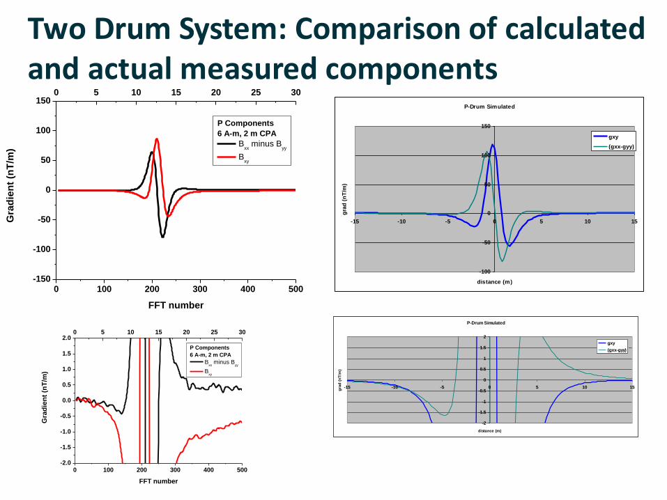
Two Drum System: Comparison of calculated and actual measured components
P-Drum Simulated
-100
-50
0
50
100
150
-15 -10 -5 0 5 10 15
distance (m)
gra
d (
nT
/m)
gxy
(gxx-gyy)
P-Drum Simulated
-2
-1.5
-1
-0.5
0
0.5
1
1.5
2
-15 -10 -5 0 5 10 15
distance (m)
gra
d (
nT
/m)
gxy
(gxx-gyy)
0 100 200 300 400 500-150
-100
-50
0
50
100
1500 5 10 15 20 25 30
Gra
die
nt
(nT
/m)
FFT number
P Components
6 A-m, 2 m CPA
Bxx
minus Byy
Bxy
0 100 200 300 400 500-2.0
-1.5
-1.0
-0.5
0.0
0.5
1.0
1.5
2.00 5 10 15 20 25 30
Gra
die
nt
(nT
/m)
FFT number
P Components
6 A-m, 2 m CPA
Bxx
minus Byy
Bxy

Measurement setup hexagonal system

Static planar tensor gradiometer
Presentation title | Presenter name44 |
• Six planar flip chip gradiometers
• 3 reference SQUID magnetometers
• Sensitivity – 2 pT/m/Hz at 10 Hz unshielded operation
Extracted tensor components from a 6 A.m2
dipole magnet pass
Gradient noise density of a single planar gradiometer
Calculated scaled moment vs the theoreticalmoment for a dipole magnet pass

Rotating Planar GradiometerR-Tensor –early development
R-Tensor is a magnetic tensor gradiometer that requires only a single rotating planar SQUID gradiometer to measure all the independent components of the magnetic gradient tensor.
45 |
• reduces system complexity (one sensor verses typically five minimum)
• significantly reduces size, weight and power (SWaP) requirements
• single rotating planar SQUID gradiometer + orthogonal referencing for field compensation (improves accuracy of some components)
• current sensitivity ~ 50 pT /(m.√Hz) @ 30 Hz (rotational rate)
• currently ~4 hours of continuous operation

Concept • 2nd Harmonic – free from common-mode
• 1st harmonic + DC contaminated with common-mode, reduced with field referencing
• Response to a moving dipole 2.8 A.m2 – CPA = 1.2 m (8 m track)
zzzyzx
yzyyyx
xzxyxx
BBB
BBB
BBB
G
f 2f
Frequency
DC
1st Harmonic2nd
Harmonic
Tensor
components
contained within
the in-phase and
quadrature of the
harmonic

HTS Devices for Communication
47 |

Josephson Junctions for High Frequency Applications
• AC Josephson Effect: ƒ (2e/h)Vo, 2e/h = 0.4836 GHz/V
V0 from V to mV, f falls into the microwave, mm, sub-mm/THz bands
Generate rf signal of variable frequency controlled by a voltage
Detect an incoming rf signal
Measure and detect voltage with extremely high precision
• Advantages of SC active devices:
extremely low noise
low power consumption (nWs)
high freq and wide band operation
(due to high-energy gap)
-2.5
-2.0
-1.5
-1.0
-0.5
0.0
0.5
1.0
1.5
2.0
2.5-2 -1 0 1 2
-1T -500G 0 500G 1T
0
10
20
30
V (mV)
no CB
1 CB
2 CB
3 CB
THz blocked
I (m
A)
spectrum
Hilb
ert
Spectr
um
(a.u
.)
Frequency (Hz)

HTS microwave passive devices developed – Low loss, high selectivity, high Q-factor
10 mm
T. Zhang, J. Du, et al. Electronics Letters, 48, (2012).
T. Zhang, J. Du, et al. Supercond. Sci. Technol. 25
(2012) 105014
T. Zhang, J. Du, et al., Physica C, 495, 69-73, 2013.
D. Bai, J. Du, et al., JAP, 114 (2013) 133906.

HTS Josephson Junction microwave active devices – some examples developed
YBCO step-edge junctions
Au film resistor
500.0M 1.0G 1.5G 2.0G 2.5G
0.0
0.2
0.4
0.6
0.8
1.0
No
rma
lise
d V
2
Freq. (Hz)
JD318F in cryocooler at 55K, IB = 390 uA, vary Ir, 2/4/09
• HTS Josephson Junction is a highly nonlinear active device.
Tuneable heterodyne GHz oscillatorSelf-pumped tuneable JJ mixer
Refs:
•J. Du and J. C. Macfarlane, Electronics Letters, 47 (2011) 772.
•J. Du, et al, Supercond. Sci. Technol. 25 (2012) 025019.
•J. Du, et al., J. Appl. Phys. 111, 053910 (2012).
• D. Bai, J. Du and Y. S. He, IEEE Trans Appl. Supercond., vol. 24 (5), 1501404, 2014.
IF
LO
RF

An advanced receiver based on HTS technology
Can enhance sensitivity & selectivity
Can achieve high-speed broadband communication
Integrate HTS passive and active components onto single chip,
i.e. MMIC (microwave monolithic integrated circuit) Josephson
junction mixer
Develop a low-noise receiver front-end

High-Tc Superconducting (HTS) Monolithic Microwave Integrated Circuit (MMIC) RF Receivers
• Stable operation between 20 to 80 K.
• Conversion gain ~-1±0.5dB at 20 K (~ 0 dB
deducted the filter Ils). The highest value
demonstrated for HTS mixers.
• On-chip Integration:
o Improve coupling efficiency
o Isolation of input and output circuits
o Remove losses due to connections
o Compactness
o Lower power consumption

High-Tc Superconducting Receiver Technology for Ka band (26.5–40 GHz) high-speed, long-range communications
Enabling:
• Inter-satellite communications
• Communications between ships and satellite, …
Demonstrated :
• a compact (2.5 x 2 x1.5
cm3),
• high-gain (40 dB) and
• low noise (~ 0.1 dB)
• Ka band HTS receiver
front-end module.

Smart Devices/Systems for Future Terahertz Communications
• Unprecedented growth in wireless communication push freq. towards millimeter and THz range
• THz – higher carrier freq. and broad bandwidth, potential for ultra high-bit rate wireless communication (tens of gigabit to terabit/s data rate).
• Problems:
• (1) High atmospheric attenuation –ultra-sensitive heterodyne mixers required
• (2) Lack components/systems (beyond microwave tech and below optical tech)
• Research Aim: develop heterodyne mixers for THz sensing and communication applications

A Ring-slot antenna - coupled HTS Step-edge JJ Harmonic Mixer – cooled on a PT cryocooler
J. Du, et al , Supercond. Sci. Technol. 29, in print, 2016
Mixing with 20th
harmonic of LO
frequency to
down-converted
from 600 GHz to
2.4 GHz
Intermediate
frequency (IF)

Broadband THz Mixer:
Principal Investigator: Dr Xiang Gao

Harmonic Mixing CharacterizationFrequency response characterization – broadband (over 24 GHz
bandwidth)
200-GHz band 600-GHz band
The black traces refer to directly measured results. The red traces refer to processed results
after calibration of the whole IF link and frequency-dependent THz source power.
To be published

RF Measurement
58 |
Temperature dependence:
Operating at T up to 77K !!
IF Output vs the harmonic number

Broadband Response: SQUID voltage power spectrum –no rf
fc
2fc
dc

Broadband response: SQUID voltage power spectrum – rfat 12GHz
fc
2fc
fRF
dc

|

SQIFs
|
Design #1 100,200 Junctions βL = 0.4
Design #2 20,000 Junctions βL = 0.4
Design #3 20,000 Junctions βL < 1
23360 V/T
5740 V/T
1530 V/T

Increasing HTS SQIF array size & sensitivity
63 |
• N= 100,200
• Substrate = 1cm2 MgO
• Scaling up to 4cm2
MgO with N= 1,000,000

Broadband RF response of HTS SQIF array
• N = 100,200
• VB = 23.3 kV/T
• Flat band response to 300 MHz
• Recent detection of multiple AM
radio stations (not shown)

Comparison of Cryocooler Alignment
65 |

Summary
• HTS step edge Josephson Junctions on MgO make good devices
• HTS gradiometers – new concept is promising with a single planar gradiometer rotated
• Various telecommunication components in HTS have been demonstrated with excellent performance • Filters are proving successful
• Full monoliths - still to clarify value
• New SQIF antennas demonstrated but still to get the sensitivity to desired levels
66 |

67 |
Real
x xImaginary
Planned
IWSSD 2016
IWSSD 2018

Thank you!
See you in Sydney 2018!