High Speed Serial Waveform Plug-in Application Printable...
47
xx High Speed Serial Waveform Plug-in Application ZZZ Printable Help Document *P077124500* 077-1245-00
Transcript of High Speed Serial Waveform Plug-in Application Printable...

xx
High Speed Serial WaveformPlug-in Application
ZZZ
Printable Help Document
*P077124500*
077-1245-00


High Speed Serial WaveformPlug-in Application
ZZZ
Printable Help Document
www.tek.com077-1245-00

Copyright © Tektronix. All rights reserved. Licensed software products are owned by Tektronix or itssubsidiaries or suppliers, and are protected by national copyright laws and international treaty provisions.
Tektronix products are covered by U.S. and foreign patents, issued and pending. Information in thispublication supersedes that in all previously published material. Specifications and price change privilegesreserved.
TEKTRONIX and TEK are registered trademarks of Tektronix, Inc.
SourceXpress ® is a registered trademark of Tektronix, Inc.
Microsoft, Windows, Windows XP Professional, and Windows 7 are registered trademarks of MicrosoftCorporation.
Supports High Speed Serial Plug-in application Version 1.0 and above.
Help part number: 076–0395–00
PDF of Help system part number: 077–1245–00
Contacting TektronixTektronix, Inc.14150 SW Karl Braun DriveP.O. Box 500Beaverton, OR 97077USA
For product information, sales, service, and technical support:In North America, call 1-800-833-9200.Worldwide, visit www.tek.com to find contacts in your area.

Table of Contents
Table of Contents
IntroductionWelcome .. . . . . . . . . . . . . . . . . . . . . . . . . . . . . . . . . . . . . . . . . . . . . . . . . . . . . . . . . . . . . . . . . . . . . . . . . . . . . . . . . . . . . . . . . . . . . . . . . . . . . . . . . . . . 1Key features . . . . . . . . . . . . . . . . . . . . . . . . . . . . . . . . . . . . . . . . . . . . . . . . . . . . . . . . . . . . . . . . . . . . . . . . . . . . . . . . . . . . . . . . . . . . . . . . . . . . . . . . . 1Documentation. . . . . . . . . . . . . . . . . . . . . . . . . . . . . . . . . . . . . . . . . . . . . . . . . . . . . . . . . . . . . . . . . . . . . . . . . . . . . . . . . . . . . . . . . . . . . . . . . . . . . . 3Support information . . . . . . . . . . . . . . . . . . . . . . . . . . . . . . . . . . . . . . . . . . . . . . . . . . . . . . . . . . . . . . . . . . . . . . . . . . . . . . . . . . . . . . . . . . . . . . . . 3
OrientationElements of the display . . . . . . . . . . . . . . . . . . . . . . . . . . . . . . . . . . . . . . . . . . . . . . . . . . . . . . . . . . . . . . . . . . . . . . . . . . . . . . . . . . . . . . . . . . . . 5Plug-in selection . . . . . . . . . . . . . . . . . . . . . . . . . . . . . . . . . . . . . . . . . . . . . . . . . . . . . . . . . . . . . . . . . . . . . . . . . . . . . . . . . . . . . . . . . . . . . . . . . . . . 5Compile button. . . . . . . . . . . . . . . . . . . . . . . . . . . . . . . . . . . . . . . . . . . . . . . . . . . . . . . . . . . . . . . . . . . . . . . . . . . . . . . . . . . . . . . . . . . . . . . . . . . . . . 6Reset Plug-in button. . . . . . . . . . . . . . . . . . . . . . . . . . . . . . . . . . . . . . . . . . . . . . . . . . . . . . . . . . . . . . . . . . . . . . . . . . . . . . . . . . . . . . . . . . . . . . . . 9Help button . . . . . . . . . . . . . . . . . . . . . . . . . . . . . . . . . . . . . . . . . . . . . . . . . . . . . . . . . . . . . . . . . . . . . . . . . . . . . . . . . . . . . . . . . . . . . . . . . . . . . . . . . . 9Enabled/disabled indicators . . . . . . . . . . . . . . . . . . . . . . . . . . . . . . . . . . . . . . . . . . . . . . . . . . . . . . . . . . . . . . . . . . . . . . . . . . . . . . . . . . . . . . 10
Pattern tab overviewPattern tab overview.. . . . . . . . . . . . . . . . . . . . . . . . . . . . . . . . . . . . . . . . . . . . . . . . . . . . . . . . . . . . . . . . . . . . . . . . . . . . . . . . . . . . . . . . . . . . . . 11Basic Settings . . . . . . . . . . . . . . . . . . . . . . . . . . . . . . . . . . . . . . . . . . . . . . . . . . . . . . . . . . . . . . . . . . . . . . . . . . . . . . . . . . . . . . . . . . . . . . . . . . . . . . 11Encoding/Modulation . . . . . . . . . . . . . . . . . . . . . . . . . . . . . . . . . . . . . . . . . . . . . . . . . . . . . . . . . . . . . . . . . . . . . . . . . . . . . . . . . . . . . . . . . . . . . 13Scrambling . . . . . . . . . . . . . . . . . . . . . . . . . . . . . . . . . . . . . . . . . . . . . . . . . . . . . . . . . . . . . . . . . . . . . . . . . . . . . . . . . . . . . . . . . . . . . . . . . . . . . . . . . 14Step Response.. . . . . . . . . . . . . . . . . . . . . . . . . . . . . . . . . . . . . . . . . . . . . . . . . . . . . . . . . . . . . . . . . . . . . . . . . . . . . . . . . . . . . . . . . . . . . . . . . . . . . 15Duty Cycle Distortion. . . . . . . . . . . . . . . . . . . . . . . . . . . . . . . . . . . . . . . . . . . . . . . . . . . . . . . . . . . . . . . . . . . . . . . . . . . . . . . . . . . . . . . . . . . . . 16Markers . . . . . . . . . . . . . . . . . . . . . . . . . . . . . . . . . . . . . . . . . . . . . . . . . . . . . . . . . . . . . . . . . . . . . . . . . . . . . . . . . . . . . . . . . . . . . . . . . . . . . . . . . . . . . 17
Transmitter tabTransmitter tab overview .. . . . . . . . . . . . . . . . . . . . . . . . . . . . . . . . . . . . . . . . . . . . . . . . . . . . . . . . . . . . . . . . . . . . . . . . . . . . . . . . . . . . . . . . 19Periodic Jitter . . . . . . . . . . . . . . . . . . . . . . . . . . . . . . . . . . . . . . . . . . . . . . . . . . . . . . . . . . . . . . . . . . . . . . . . . . . . . . . . . . . . . . . . . . . . . . . . . . . . . . 19Random Jitter . . . . . . . . . . . . . . . . . . . . . . . . . . . . . . . . . . . . . . . . . . . . . . . . . . . . . . . . . . . . . . . . . . . . . . . . . . . . . . . . . . . . . . . . . . . . . . . . . . . . . . 20Noise . . . . . . . . . . . . . . . . . . . . . . . . . . . . . . . . . . . . . . . . . . . . . . . . . . . . . . . . . . . . . . . . . . . . . . . . . . . . . . . . . . . . . . . . . . . . . . . . . . . . . . . . . . . . . . . . 22Pre/De-Emphasis . . . . . . . . . . . . . . . . . . . . . . . . . . . . . . . . . . . . . . . . . . . . . . . . . . . . . . . . . . . . . . . . . . . . . . . . . . . . . . . . . . . . . . . . . . . . . . . . . . 23Spread Spectrum Clocking . . . . . . . . . . . . . . . . . . . . . . . . . . . . . . . . . . . . . . . . . . . . . . . . . . . . . . . . . . . . . . . . . . . . . . . . . . . . . . . . . . . . . . . 25
Channel tabS-Parameter license . . . . . . . . . . . . . . . . . . . . . . . . . . . . . . . . . . . . . . . . . . . . . . . . . . . . . . . . . . . . . . . . . . . . . . . . . . . . . . . . . . . . . . . . . . . . . . . 29Channel tab overview .. . . . . . . . . . . . . . . . . . . . . . . . . . . . . . . . . . . . . . . . . . . . . . . . . . . . . . . . . . . . . . . . . . . . . . . . . . . . . . . . . . . . . . . . . . . . 29Intersymbol Interference.. . . . . . . . . . . . . . . . . . . . . . . . . . . . . . . . . . . . . . . . . . . . . . . . . . . . . . . . . . . . . . . . . . . . . . . . . . . . . . . . . . . . . . . . . 30S-Parameters . . . . . . . . . . . . . . . . . . . . . . . . . . . . . . . . . . . . . . . . . . . . . . . . . . . . . . . . . . . . . . . . . . . . . . . . . . . . . . . . . . . . . . . . . . . . . . . . . . . . . . . 30
S-Parameter file descriptions . . . . . . . . . . . . . . . . . . . . . . . . . . . . . . . . . . . . . . . . . . . . . . . . . . . . . . . . . . . . . . . . . . . . . . . . . . . . . . . . 33Aggressor signals . . . . . . . . . . . . . . . . . . . . . . . . . . . . . . . . . . . . . . . . . . . . . . . . . . . . . . . . . . . . . . . . . . . . . . . . . . . . . . . . . . . . . . . . . . . . . 35
High Speed Serial Printable Help Document i

Table of Contents
Batch Compile tabBatch compile tab overview .. . . . . . . . . . . . . . . . . . . . . . . . . . . . . . . . . . . . . . . . . . . . . . . . . . . . . . . . . . . . . . . . . . . . . . . . . . . . . . . . . . . . . 37
LicensingLicensing . . . . . . . . . . . . . . . . . . . . . . . . . . . . . . . . . . . . . . . . . . . . . . . . . . . . . . . . . . . . . . . . . . . . . . . . . . . . . . . . . . . . . . . . . . . . . . . . . . . . . . . . . . . 39
Index
ii High Speed Serial Printable Help Document

Introduction Welcome
Welcome
The High Speed Serial (HSS) plug-in is a waveform creation application that takes an input pattern andcreates pre-distorted waveforms to test a device's conformance to standards.
The High Speed Serial plug-in is designed to integrate and operate seamlessly as an enhancement to theSourceXpress waveform creation software application or to an AWG70000A series arbitrary waveformgenerator.
Once installed, the plug-in becomes available as another waveform plug-in application.
This illustration shows the High Speed Serial plug-in viewed from the SourceXpress application. Theplug-in is identical whether it is used from SourceXpress or from an AWG70000A series instrument.
Key features
Jitter Generation: Up to four different sinusoidal jitters with different amplitudes, frequencies andphases can be added to a base pattern. Three independent band-limited random jitters can alsobe added to the base pattern.
Inter Symbol Interference (ISI) Creation: Directly create ISI.
S-Parameters: Scattering parameters can be directly convolved with the base pattern to recreate thechannel characteristics. S-Parameters can be entered directly from an S-Parameter file captured froma Tektronix sampling oscilloscope. By applying an inverse filter, the effects of the channel can be
High Speed Serial Printable Help Document 1

Introduction Key features
de-embedded from the circuit. Cascading S-Parameters allows you to cascade up to six Touchstonefiles of the same format to emulate a cascaded channel.
Noise: Vertical noise can be added at both near and far ends of the channel.
Idle State: Standards like SATA call for OOB signaling which requires an idle state followed by aburst. You can directly create this idle state without using additional power dividers. Noise can also beadded to these idle state waveforms.
Batch Processing: When more than one pattern needs to be synthesized, you can use batch processingto create multiple waveforms with a combination of one random and maximum of 2 sinusoidal jitter
Sequencing: You can add compiled waveforms directly to existing sequences or create sequencesusing the Batch Compile feature.
Marker outputs: Marker outputs can be configured to be the same as the input base pattern or togenerate clocks at a user-defined frequency. You can also set the marker output to all high, all low,or trigger.
Pre/de-emphasis and Preshoot: Provides flexibility to program the Pre/De-emphasis and Preshootsample by sample. The preview feature facilitates you to arrive at the most optimized Pre/de-emphasisfor a particular channel quickly.
Scrambling and 8B10B encoding: The input data pattern can be scrambled by defining a polynomial.You can also encode using the 8B10B encoding option. 8B10B encoding works with D and Ksymbol pattern only.
NRZ, NRZ-I, PAM, and PWM: Allows you to define the pattern duty cycle using the Pulse WidthModulation (PWM), and alternatively encode the bit stream to 4- 8- 16-PAM, NRZ, or NRZ-I.
2 High Speed Serial Printable Help Document

Introduction Documentation
Documentation
In addition to this application Help system, the following documentation is available for the software.
All documentation is available on the Tektronix Web site (www.tektcom/manual/downloads ).
To read about Use these documents
High Speed Serial plug-in operation and userinterface help
Access the plug-in application help from the plug-in Help menu forinformation on all controls and elements on screen.
The High Speed Serial plug-in help system is also available in PDFformat located in the program’s installation folder and also available onthe Tektronix web site.
High Speed Serial plug-in programmercommands
Access the plug-in programmer manual for the syntax of remote commandsspecific to the plug-in.
This is available on the Tektronix web site.
SourceXpress operation and user interface help Access the SourceXpress application help from the Help menu forinformation on all controls and elements on screen.
The SourceXpress help system is also available in PDF format, availableon the Tektronix web site.
SourceXpress programmer commands Access the SourceXpress programmer manual for the syntax of remotecommands.
This document is available in PDF format located in the program’sinstallation folder and also available on the Tektronix web site.
Connected instrument operation and userinterface help (such as an AWG70002A)
For operation and interface help of a connected instrument, refer to theinstrument’s documentation.
This is available with the instrument or on the Tektronix web site.
Connected instrument programmer commands(such as an AWG70002A)
For programming information of a connected instrument, refer to theinstrument’s documentation. This is available with the instrument or onthe Tektronix web site.
xxx
Support information
Tektronix offers the following services in support of their products:
Technical Support. For application-related questions about a Tektronix product, contact us bytelephone or email ).
Service Support. For service-related questions about a Tektronix product, contact us by telephoneor email ).
Tektronix also offers extended warranty and calibration programs as options on many products. Contactyour local Tektronix distributor or sales office.
High Speed Serial Printable Help Document 3

Introduction Support information
4 High Speed Serial Printable Help Document

Orientation Elements of the display
Elements of the display
The main areas of the application window are shown in the following figure.
Plug-in selection
Use the Plug-in pull-down menu to select the High Speed Serial plug-in application. The plug-in pull-downmenu varies depending the installed applications.
NOTE. High Speed Serial requires a license to create waveforms.
Refer to Licensing (see page 39).
High Speed Serial Printable Help Document 5

Orientation Compile button
Compile button
Use the Compile button to create the waveforms and place the waveforms into the Waveforms list of thehost application.
Use the Compile settings button to edit the compilation settings.
6 High Speed Serial Printable Help Document

Orientation Compile button
Compile settings
Item Description
Name The application provides a base name for compiled waveforms. You can edit the fieldwith a name of your choice. The waveform is added to the Waveforms list. If the namealready exists, the name is incremented with a numerical value (unless the overwriteoption is selected).
The Reset Plug-in button resets the Name field to the default name.
Overwrite existingwaveform
If checked, a waveform with the same name (in the waveforms list) is overwritten with nowarnings.
Compile for Choose the channel to associate with the compiled waveform.
Single channel instruments default to the single channel.
Compile only The compiled waveforms are simply entered into the Waveforms list.
High Speed Serial Printable Help Document 7

Orientation Compile button
Item Description
Compile and assign to The compiled waveforms are entered into the Waveforms list and automatically assignedto the selected channel.
Play after assign If checked, the waveform starts to play out immediately after compiling.
Add to an existing sequence The compiled waveforms are entered into the Waveforms list and added to the specifiedsequence.
There must be at least one sequence available in the Sequences list.
Sequences Use the pull-down list to view the available sequences.
Tracks Use the pull-down list to select the track the of the specified sequence to append thewaveform.
Sampling Rate
Auto Calculate SampleRate
This is the default method to set the sampling rate. The application creates a samplingrate based on the settings chosen for the waveform.
Manual Sampling Rate Select to enter a specific sampling rate.
Samples/Unit Interval Enter the samples per UI of the waveform
A unit interval (UI), also referred to as a bit time, is the time taken in a data stream for onebit. For example, in a serial line with a baud rate of 2.5 Gb/s, a unit interval is 1/(2.5Gb/s) = 0.4 ns.
This value, either calculated or user defined, determines the number of Coefficientsavailable when adding Pre- or De-Emphasis.
Apply Corrections File You can apply a correction file directly to the waveform when compiling.
Correction file Path: When applying a correction file, navigate to the location of the file.
Use the browse folder icon to navigate to a saved correction file.
Once a valid file path is entered, the Correction Settings icon is enabled. Select todisplay the Frequency Response (see page 9) screen.
Auto Repeat Count When compiling a waveform, the waveform must meet the minimum waveform lengthrequirement for the instrument (to be a valid waveform). If the current setup would createa waveform of invalid length, the system automatically repeats the waveform until theminimum length is reached.
Auto Repeat Count enabled (default mode):
If necessary, the waveform is automatically repeated until it meets the minimum waveformlength requirement.
Auto Repeat Count disabled:
When disabled, you are presented with a control to either set a number of times to repeatthe waveform, or to enter a waveform length in time.
If the manual setting would cause a waveform of insufficient length, the softwareautomatically increases the repeat count so that a valid waveform is generated. If thishappens, a warning message is displayed informing you of the event.
If the manual setting causes a waveform that exceeds the maximum waveform lengthallowed, an error message is displayed and no waveform is created.
Compile Compiles the waveform.
xxx
8 High Speed Serial Printable Help Document

Orientation Reset Plug-in button
Correction file frequency response
When applying an RF correction file, the Frequency Response screen shows plot information and providesAdvanced options to apply a Gaussian filter or remove Sin(x)/x distortions.
Reset Plug-in button
Returns the plug-in features and settings to their default values.
Help button
Help button: Provides links to open the application help.
Item Description
User manual Opens the plug-in help system.
About ... Provides you with information about your plug-in application. This information ishelpful when contacting Tektronix about your application.
xxx
High Speed Serial Printable Help Document 9

Orientation Enabled/disabled indicators
Enabled/disabled indicators
All distortion types that can be enabled or disabled include a status indicator in their tab. This provides aview of which distortions currently enabled (turned on) for use when compiling a waveform.
Blue indicates the distortion is turned on.
Turning off a distortion type means it will not be used while compiling. But all settings remain, allowingyou to quickly add the distortion.
10 High Speed Serial Printable Help Document

Pattern tab overview Pattern tab overview
Pattern tab overview
This tab allows users to set the basic pattern for waveform generation including encoding and modulationschemes along with scrambling. In addition to this, users can enable DCD and step response to includerise/fall time effects on the waveform. You can also include markers with desired settings.
Basic SettingsTable 1:
Item Description
Base Pattern Data
Pattern Select the pattern type.
Clock This generates a waveform with clock-like bit pattern of alternate 0s and 1s.
All Zero This generates a waveform with an amplitude corresponding to the maximum negativevoltage level.
All One This generates a waveform with an amplitude corresponding to maximum positivevoltage level.
IdleState Enter the idle state value (in samples or secs) of the waveform.
Idle state is the state used for some standards like SATA. During this state, the valueis neither 0 or 1. It is a state during which no valid data is transferred between thetransmitter and the receiver. SourceXpress supports Idle state waveforms with idlevalue and idle offset.
Idle state waveforms are individual waveforms that can be sent to the AWG. Thewaveforms contain the DC values with no base data during this state. You can add thenumber of samples and noise as required in the idle state waveform.
NOTE. All other features of the High Speed Serial plug-in are disabled (except forNoise) when IdleState is selected as the Pattern.
High Speed Serial Printable Help Document 11

Pattern tab overview Basic Settings
Table 1: (cont.)
Item Description
Idle State Offset Enter the offset value (in Volts) of the waveform.
This is available only when Pattern is set to IdleState.
Idle State Time Enter the amount of time the Idle State Offset value is held.
PRBS Select one of the available PRBS patterns.
You can also define a custom PRBS pattern with the PRBS Editor. Set the Pattern typeto User Defined PRBS and click the Settings icon to display the editor.
Pattern Select the pattern type.
• Binary
• Hex
• Symbol
Based on the type, enter the pattern. You can also copy and paste a pattern directlyinto the pattern field. You can enter up to 512 characters.
File Click the folder icon to navigate to a pattern file.
Invert Bits Use the Invert Bits to create an inverted signal. For example, an input bit stream of011000 will create a signal of 100111 when the Invert Bits option is enabled.
Data Rate Specify the data rate (in bps) of the waveform.
Amplitude
Maximum Specify the maximum amplitude (in volts) of the waveform.
Range: dependent on instrument.
Minimum Specify the minimum amplitude (in volts) of the waveform.
Range: dependent on instrument.
xxx
12 High Speed Serial Printable Help Document
Pattern tab overview Encoding/Modulation
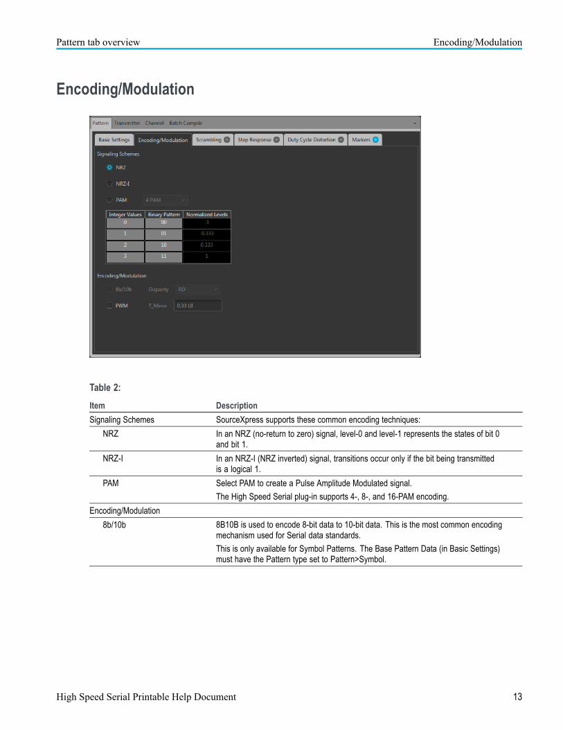
Encoding/Modulation
Table 2:
Item Description
Signaling Schemes SourceXpress supports these common encoding techniques:
NRZ In an NRZ (no-return to zero) signal, level-0 and level-1 represents the states of bit 0and bit 1.
NRZ-I In an NRZ-I (NRZ inverted) signal, transitions occur only if the bit being transmittedis a logical 1.
PAM Select PAM to create a Pulse Amplitude Modulated signal.
The High Speed Serial plug-in supports 4-, 8-, and 16-PAM encoding.
Encoding/Modulation
8b/10b 8B10B is used to encode 8-bit data to 10-bit data. This is the most common encodingmechanism used for Serial data standards.
This is only available for Symbol Patterns. The Base Pattern Data (in Basic Settings)must have the Pattern type set to Pattern>Symbol.
High Speed Serial Printable Help Document 13

Pattern tab overview Scrambling
Table 2: (cont.)
Item Description
Running Disparity 8B/10B encoding scheme uses the difference between the total number of ones andzeros transmitted to encode the present symbol. This difference is referred to as therunning disparity. Its value is limited to +1 (RD+) or –1 (RD–).
PWM Select PWM to generate a Pulse Width Modulated signal.
• T_Minor: Enter a value for T_Minor as a fraction of the UI (unit interval).
In the PWM scheme, each bit is represented in terms of a 0 followed by 1. In orderto distinguish between the original bits, the T_Minor parameter is used to specify theduration of the encoded bit 0 (or 1) with respect to the original unit interval (UI). In casethe original bit was a 0, then T_Minor specifies the width of the encoded bit 0. If theoriginal bit was 1, then T_Minor specifies the width of the encoded bit 1.
xxx
ScramblingItem Description
Scrambling Type Scrambles the input data pattern with a Polynomial
• Additive
• Multiplicative
Polynomial Specify the scrambling polynomial expression.
Define a polynomial expression such as X16+X14+1.
Register Initial Value Specify the register initial values and select the format (Hex or Binary). The length ofthe register is equal to the degree of the polynomial.
• Binary
• Hex
xxx
14 High Speed Serial Printable Help Document

Pattern tab overview Step Response
Step Response
Step Response defines the rise and fall time edges of the waveform. Rise and fall times can be definedin UI or seconds.
Item Description
Rise Elapsed time between the low reference level crossing and the high reference levelcrossing on the rising edge of the waveform. It is measured in time units between the10% and 90% levels or between the 20% and 80% levels.
Set the rise time in UI or seconds from 0.05 UI to 0,5 UI (50 ps to 500 ps)
• First Order conveys an exponential transition between the low and high level.
• Linear conveys a linear transition between the low and high level.
Fall Elapsed time between the high reference level crossing and the low reference levelcrossing on the falling edge of the waveform. It is measured in time units between the10% and 90% levels or between the 20% and 80% levels.
Set the rise time in UI or seconds from 0.05 UI to 0,5 UI (50 ps to 500 ps)
• First Order conveys an exponential transition between the low and high level.
• Linear conveys a linear transition between the low and high level.
Rise/Fall Time Define how the rise time and fall time are measured.
• 20/80: Measured between 20% and 80% of the signal amplitude.
• 10/90: Measured between 10% and 90% of the signal amplitude.
xxx
High Speed Serial Printable Help Document 15

Pattern tab overview Duty Cycle Distortion
Duty Cycle Distortion
Duty Cycle Distortion (DCD) is the portion of the deterministic jitter directly correlated with waveformpolarity (the difference in the positive edges and negative edges). The duty cycle can be defined in UIor seconds.
16 High Speed Serial Printable Help Document

Pattern tab overview Markers
Markers
Markers are used to help synchronize equipment. Use the Markers tab to enable markers and definethe marker parameters.
Item Description
Marker 1
and
Marker 2
Enable markers. The markers can be independently defined.
Base Pattern Marker matches the base pattern.
Clock Define the clock frequency based on the selected data rate.
• Data Rate
• Data Rate/2
• Data Rate/4
• Data Rate/8
• User-Defined, Range: 1 Hz to Data Rate
High/Low • All High
• All Low
• Trigger: Define the marker to transition (High To Low or Low To High) at the setnumber of samples.
xxx
High Speed Serial Printable Help Document 17

Pattern tab overview Markers
18 High Speed Serial Printable Help Document

Transmitter tab Transmitter tab overview
Transmitter tab overview
The transmitter tab allows user to include timing impairments like Periodic Jitter, Random Jitter, andSpread Spectrum Clocking during waveform compilation. In addition to this, users can also includeamplitude impairments like Noise, and specify the Pre-Emphasis scheme and set the appropriate valueson the waveform.
Periodic Jitter
Use the Periodic Jitter tab to introduce one or more sine waves as periodic jitter.
Periodic Jitter is the portion of the deterministic jitter that is periodic, but for which the period is notcorrelated with any data in the waveform. It is measured by peak-to-peak variation and frequency.
NOTE. If Batch Compile is enabled, the Periodic Jitter tab is disabled.
High Speed Serial Printable Help Document 19

Transmitter tab Random Jitter
Enable Periodic Jitter by selecting at least one of the Periodic Jitter (PJ) check boxes and enter theparameters.
Item Description
PJ1 — PJ4
Magnitude Set the magnitude of the sine wave (jitter) (in UI) to introduce.
Range: 0 UI to 50 UI
Phase Set the phase of the sine wave (jitter) (in degrees) to introduce.
Frequency Set the frequency of the sine wave (jitter) (in Hz) to introduce.
Range: 10 kHz to ½ Data rate.
Integer Cycles Select to ensure that there is an integer number of sinusoidal jitter cycles over theentire bit pattern under consideration. In some cases, the bit pattern might be repeatedto meet this requirement.
Deviation Users can indicate the choice of either allowing the software to automatically decide thefinal sinusoidal frequency by using 'Auto' or provide the maximum allowable variationas a percentage of the dialed sinusoidal frequency by using the 'Manual' mode.
• Auto: The software to automatically decides the final sinusoidal frequency.
• Manual: Enter the maximum allowable variation as a percentage of the dialedsinusoidal frequency.
xxx
Random Jitter
Random Jitter is jitter that does not exhibit deterministic behavior and is not bounded. It can be describedby a Gaussian probability distribution. It is characterized by standard deviation value (RMS).
NOTE. If Batch Compile is enabled, the Random Jitter tab is disabled.
20 High Speed Serial Printable Help Document

Transmitter tab Random Jitter
Item Description
RJ1 — RJ3
Magnitude (RMS) Set the magnitude of the jitter (in UI or seconds) to introduce.
Range: 0.001 UI to 0.5 UI (1 ps to 500 ps).
Low-Frequency Set the low frequency of the random jitter (in Hz) to introduce.
Range: 1 kHz to (High-Frequency – 10 kHz).
High-Frequency Set the high frequency of the random jitter (in degree) to introduce.
Range: 1 kHz to ½ Data rate.
Seed
(RJ1 only)
Select to use the same random jitter sequence during each compilation. The requiredrandom jitter sequence is generated through a 5-digit seed. By keeping the 5-digit seedconstant, the same random jitter sequence is generated during each compilation.
When not selected, the uncorrelated random jitter sequence is generated duringeach compilation.
Range: 1 to 99999
Crest Factor
(RJ1 only)
Select to apply the required crest factor value of Rj1 to the serial data.
When you enable Rj1 with a specified RMS value within a short signal duration, it willnot reach the peak value. By enabling this, a required crest factor value of Rj1 isapplied to the serial data during data transmission.
For example, if the Rj1 crest factor is set to 12 and magnitude (RMS) for Rj1 is 0.05 UI,then the Rj1 peak value is 12 x 0.05 = 0.6 UI.
Range: 1 to 20
xxx
High Speed Serial Printable Help Document 21

Transmitter tab Noise
Noise
This is a type of additive noise that modifies the vertical amplitude of the serial data and contributesto the jitter.
Item Description
Type • Near-End: This type of noise corresponds to random amplitude variations on thewaveform before it enters the channel.
• Far-End: This type of noise corresponds to the random amplitude variations of thewaveform at the far-end of the channel.
Magnitude Enter the amplitude of the noise (in volts) to generate.
Frequency • Full Bandwidth: Generates white noise between 0 Hz to Fs/2 Hz. The noisegenerated is independent for each compilation.
• Single Tone: Generates sine noise at the specified frequency. The frequency canbe a maximum of half of the data rate.
xxx
NOTE. When noise is added to a differential waveform, its amplitude appears doubled. This is because thenoise is generated in the application and appears as a waveform output for AWG.
Limitation of pattern length on randomness
The noise is created as part of the waveform data. Due to AWG memory limitations, the waveform datahas finite length. This limits randomness of the noise. The larger the waveform length, the greater is therandomness of the noise. The AWG70000A series supports waveforms up to 16 G samples on a singlechannel model (8G on a two channel model). Randomness of the noise pattern is limited by waveformlength. In the AWG continuous mode, the waveform repeats, thus the noise pattern repeats. This limitationof the AWG pattern length applies to random jitter.
22 High Speed Serial Printable Help Document

Transmitter tab Pre/De-Emphasis
Pre/De-Emphasis
Scale and Unit Intervals
Select the units scale for the Tap Coefficients (dB or Linear). The setting defines the units for bothPre/De-Emphasis and Preshoot. Also note the Samples/Unit Interval setting.
Item Description
Units for Tap Coefficients The tap coefficients defines the incremental voltage on the pre-emphasized bit.
• dB Scale: Range –20 dB to +20 dB.
• Linear Scale: Range 0.1 to 10.
Maximum Number ofSamples/Unit Interval =
The Maximum Number of Samples/Unit Interval displayed is defined by theSamples/Unit Interval set in the Compile Settings. See Compile button (see page 6).The value is set to the nearest whole number. The maximum number of coefficients issix, although the Samples/Unit Interval can exceed six.The value is set to the nearest whole integer based on the Samples/Unit Interval listedin the Compile Settings.
xxx
High Speed Serial Printable Help Document 23

Transmitter tab Pre/De-Emphasis
Pre/De-Emphisis
Item Description
Number of Taps Up to five taps are available for Pre/De-Emphisis.
NOTE. This is reduced to one tap if enabling Preshoot.
Pre/De-Emphisis Type Select the type to use.
• UI-Constant: Pre/De-emphasis is applied to all the samples in the UI.
• UI-Linear: Pre/De-emphasis is applied to all the samples in the UI linearly
• Fractional: Pre/De-emphasis is applied to a fraction of the UI.
Units for Tap Coefficients The tap coefficients defines the incremental voltage on the pre-emphasized bit.
• dB Scale: Range –20 dB to +20 dB.
• Linear Scale: Range 0.1 to 10.
xxx
Preshoot
24 High Speed Serial Printable Help Document

Transmitter tab Spread Spectrum Clocking
Item Description
Number of Taps Only one tap is available for Preshoot.
Preshoot Type Select the type to use.
• UI-Constant: Preshoot is applied to all the samples in the UI.
• UI-Linear: Preshoot is applied to all the samples in the UI linearly
• Fractional: Preshoot is applied to a fraction of the UI.
Units for Tap coefficients The tap-coefficients defines the incremental voltage on the pre-emphasized bit. For dB,the value ranges from –20 dB to +20 dB. For Volt, the value ranges from 0.1 V to +10 V.
The units in which the tap-coefficients are specified is defined with the Units For TapCoefficients (dB or Linear).
xxx
Plot view
The plot view helps you quickly arrive at the most optimized Pre/De-Emphasis and/or Preshoot for aparticular channel.
Item Description
Preview Displays the affects of the Pre/De-Emphasis and Preshoot coefficients.
Reset Sets all coefficients to their default values.
xxx
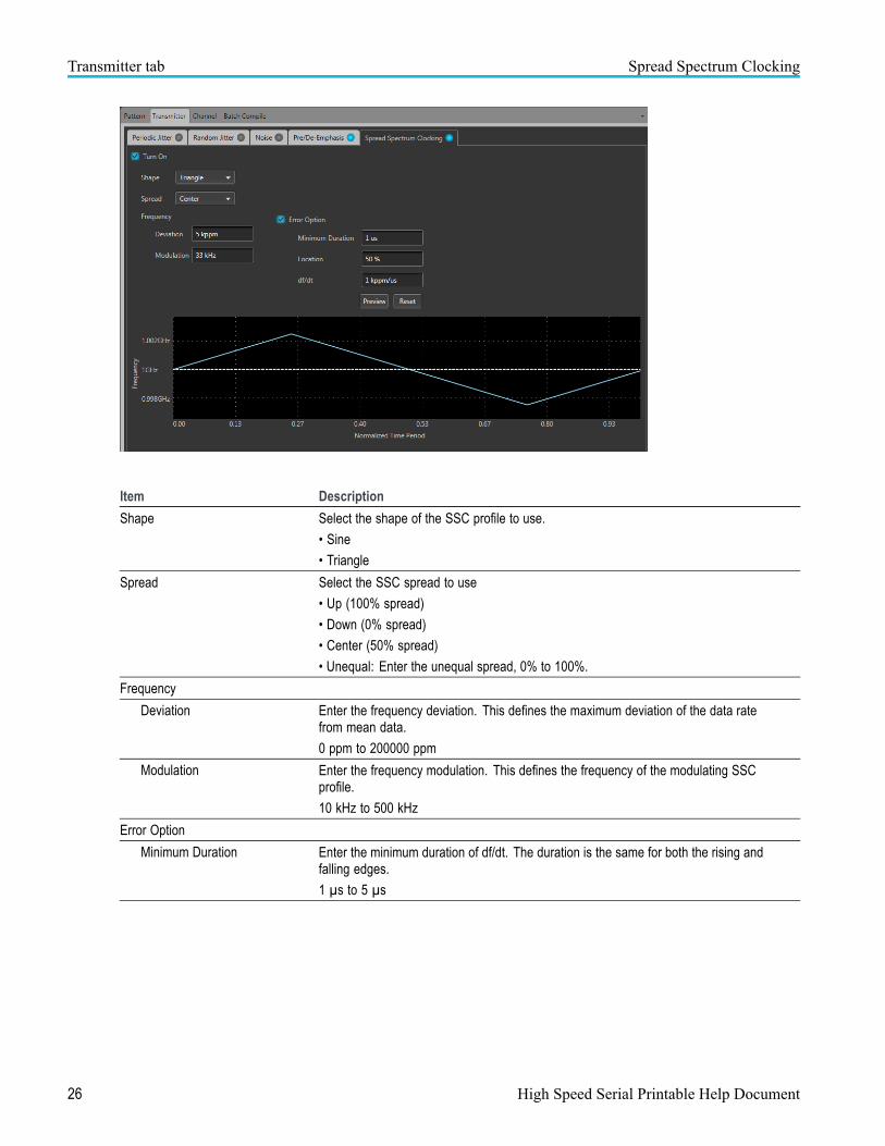
Spread Spectrum Clocking
Spread Spectrum Clocking (SSC) is the technique of modulating the clock frequency to minimize electromagnetic induction (EMI) effects. SSC is generated with a profile having a frequency and frequencydeviation.
Spread Spectrum Clocking license. An SSC license is required to use the Spread Spectrum Clockingfeatures. With the license installed on the host PC where SourceXpress is installed, SSC is availableregardless of connecting to a virtual generator or a real instrument. Refer to Licensing (see page 39) forinformation about obtaining a license file.
High Speed Serial Printable Help Document 25
Transmitter tab Spread Spectrum Clocking
Item Description
Shape Select the shape of the SSC profile to use.
• Sine
• Triangle
Spread Select the SSC spread to use
• Up (100% spread)
• Down (0% spread)
• Center (50% spread)
• Unequal: Enter the unequal spread, 0% to 100%.
Frequency
Deviation Enter the frequency deviation. This defines the maximum deviation of the data ratefrom mean data.
0 ppm to 200000 ppm
Modulation Enter the frequency modulation. This defines the frequency of the modulating SSCprofile.
10 kHz to 500 kHz
Error Option
Minimum Duration Enter the minimum duration of df/dt. The duration is the same for both the rising andfalling edges.
1 µs to 5 µs
26 High Speed Serial Printable Help Document

Transmitter tab Spread Spectrum Clocking
Item Description
Location Enter the location of df/dt. This specifies the location (in % of height) of the df/dtspike on both the edges. The spikes are located symmetrically on both the risingand falling edges.
1 ppm/µs to 5000 ppm/µs
df/dt Enter the df/dt of the waveform. This defines the sudden deviation (spikes) of theSSC profile from the predefined pattern.
xxx
High Speed Serial Printable Help Document 27

Transmitter tab Spread Spectrum Clocking
28 High Speed Serial Printable Help Document

Channel tab S-Parameter license
S-Parameter license
An S-Parameter license is required to use the Channel features (Intersymbol Interference or S-Parameters).
The Channel features are available when a license is detected by the application. With the license installedon the host PC where SourceXpress is installed, S-Parameters is available regardless of connecting to avirtual generator or a real instrument.
Refer to Licensing (see page 39) for information about obtaining a license file.
Channel tab overview
Channel tab allows users to choose the appropriate channel emulation model using either a knownIntersymbol Interference (ISI) value or through Scattering Parameters (S-Parameters) data.
High Speed Serial Printable Help Document 29

Channel tab Intersymbol Interference
Intersymbol Interference
Inter Symbol Interference (ISI) is generated due to the limited bandwidth of the channel.
Enable Intersymbol Interference to simulate the effect of ISI by directly entering the ISI value.
When ISI is 0, no ISI is introduced through the filter. However, the signal will contain some ISI dependingon various parameters like bit pattern, rise/fall time, data rate, connecting cables, and so on.
Item Description
Intersymbol Interference Value Enter the ISI value in UI or seconds.
Range: 0.01 UI to 0.5 UI (10 ps to 500 ps).
When ISI is 0, no ISI is introduced through the filter. However, the signal will containsome ISI depending on various parameters like bit pattern, rise/fall time, data rate,connecting cables, and so on.
Normalized Channel Bandwidth
(With respect to Data Rate)
ISI can also be represented in terms of the channel bandwidth normalized to the DataRate. Since ISI arises due to band-limited nature of the channel, specifying the channelbandwidth normalized to the data rate is another way of specifying the ISI.
xxx
S-Parameters
Enable S-Parameters to apply scattering parameters to the waveform.
Below is a sample S-Parameter dialog screen with the Number of Ports set to 4. The dialog screen changesto accommodate the Number of Ports selected.
The information provided for S-Parameters applies to both the Non-Cascading and Cascading modes.
30 High Speed Serial Printable Help Document

Channel tab S-Parameters
High Speed Serial Printable Help Document 31

Channel tab S-Parameters
Item Description
Mode Select Non-Cascading or Cascading S-Parameter mode.
In the Non-Cascading mode, you apply S-Parameter characteristics on the signalfrom only one S-Parameter file.
In the Cascading mode, you can cascade up to six S-Parameter files in Stages andapply the characteristics on the signal. You can select the files to apply by turning onor turning off the corresponding Stages shown in the display. All the selected filesshould be of the same type. The settings depend on the selected type of file.
The files supported are s1p, s2p, s4p, s6p, s8p, and s12p.
De-embed(Non-Cascading mode)
Cascading De-embed(Cascading mode)
Check the box to invert the S-Parameters from the signal. This removes the effectsof the component (for which the S-Parameters were created) from the signal path.
Bandwidth Auto – The bandwidth is defined at the point where the signal rolls off to -60 dB. Ifthis results in a bandwidth greater than the instrument supports, the bandwidth is setto ½ of the waveform’s sample rate (i.e. Nyquist Frequency).
Full Bandwidth – The bandwidth is set to ½ of the waveform’s sample rate (i.e.Nyquist Frequency).
Manual – The bandwidth can set by the user from 1 Hz to ½ of the maximum samplerate of the instrument. If the set Bandwidth is greater than the Nyquist (Sample rateof the waveform/2), then the software limits the bandwidth to ½ of the waveform’ssample rate. A warning message is provided.
32 High Speed Serial Printable Help Document

Channel tab S-Parameters
Item Description
Number of Ports Choose the number of ports. The port matrixes supported are 1, 2, 4, 6, 8, and 12.
The number of ports selected determines:
• The type of S-Parameter file to apply
• The Signalling Scheme choice
• The port matrixes available
S-Parameter File Navigate to the Touchstone file to apply to the signal. The type of Touchstone filesthat you are able to open is dependent on the number of ports selected. For instance,only .s4p files can be opened if the Number of Ports is set to 4.
The files supported are s1p, s2p, s4p, s6p, s8p, and s12p.
Signalling Scheme
(Only for 4, 8, and 12 ports)
Signle-Ended: If the data is single-ended, you must map the port numbers as used inthe file to physical locations in your link.
Differential: If the data is differential, you must select the data layout in the file.
Selection of the port
(No port selection for 1 Portenvironments)
Use the diagrams to map the ports for the transmitter ports (Tx-Port) and the receiverports (Rx-Port).
When choosing the number of Ports, you are presented with an active diagram ofthe ports. The diagram presented reflects the Number of Ports selected and theSignalling Scheme (if appropriate for the ports selected).
Victim
Aggressor and Both
(Only for 8 and 12 ports)
Victim: The default setting with no cross-talk effects.
Aggressor: Select this to activate aggressor signal parameters, adding the effectof cross-talk.
Port Selection The Port Selection button is available only when in Cascading mode. Press thePort Selection button to display an active dialog screen to map the ports for thetransmitter ports (Tx-Port) and the receiver ports (Rx-Port) for each stage.
xxx
S-Parameter file descriptions
1-port
Files with one port of data contain only one S-Parameter file (s1p) so they do not require any further input.
High Speed Serial Printable Help Document 33

Channel tab S-Parameters
2-port
Files with data for two ports contain four S-Parameters as a 2x2 matrix. These are Touchstone 2-port files(s2p). A dialog box is created to define the 2-port mapping.
4-Port
Files with data for four ports contain 16 S-Parameters as a 4x4 matrix. These are Touchstone 4-port files(s4p). They may contain single-ended or differential data. A dialog box is created to define the 4-portmapping for either single-ended or differential data.
If the data is single-ended, you must map the port numbers as used in the file to physical locations inyour link.
You can select the port for both transmitter and receiver from the drop-down list. Each drop-down listhas ports from 1 to 2.
If the data is differential, you must select the data layout in the file.
6-port
Files with data for six ports contain 36 S-Parameters as a 6x6 matrix. These are Touchstone 6-port files(s6p). A dialog box is created to define the 6-port mapping.
8-Port
Files with data for eight ports contain 64 S-Parameters as an 8x8 matrix. These are Touchstone 8-port files(s8p). They may contain single-ended or differential data. A dialog box is created to define the 8-portmapping for either single-ended or differential data.
If the data is single-ended, you must map the port numbers as used in the file to physical locations inyour link.
You can select the port for both transmitter and receiver from the drop-down list. Each drop-down listhas ports from 1 to 4.
If the data is differential, you must select the data layout in the file.
12-Port
Files with data for 12 ports contain 144 S-Parameters as an 12x12 matrix. These are Touchstone 12-portfiles (s12p). They may contain single-ended or differential data. A dialog box is created to define the12-port mapping for either single-ended or differential data.
If the data is single-ended, you must map the port numbers as used in the file to physical locations inyour link.
You can select the port for both transmitter and receiver from the drop-down list. Each drop-down listhas ports from 1 to 6.
If the data is differential, you must select the data layout in the file.
34 High Speed Serial Printable Help Document

Channel tab S-Parameters
Aggressor signals
8 and 12 port S-Parameters allows you to activate aggressor signal parameters and to add the effect ofcross-talk. 12 port S-Parameters allows 2 Aggressor signal parameters.
Aggressors can be added in either Non-Cascading Mode or Cascading Mode.
The Aggressor signal parameters include:
Item Description
Signal Choose the type of aggressor signal with the dropdown list:
• Clock: Indicates that the aggressor signal is a clock pattern.
• PBRS: Also choose the number of bits
• File: Indicates that the aggressor signal is another pattern file. Navigate tothe Pattern file
• Same as victim: The signal flow of the aggressor is same as the victim.
Data Rate Specify the data rate (in bps) of the signal.
This is not available when the Aggressor signal is set to be the same as the victim.
Aggressor Amplitude Enter the signal amplitude.
This is not available when the Aggressor signal is set to be the same as the victim.
Crosstalk Type Choose the type of crosstalk of the aggressor signal.
• Near-End Crosstalk
• Far-End Crosstalk
• Both
xxx
High Speed Serial Printable Help Document 35

Channel tab S-Parameters
36 High Speed Serial Printable Help Document

Batch Compile tab Batch compile tab overview
Batch compile tab overview
Batch Compile creates multiple waveforms with random jitter, periodic jitter, or a combination of both.
NOTE. Batch Compile is disabled if Periodic Jitter or Random Jitter is enabled in the Transmitter tab.
Item Description
Periodic Jitter
Integer Cycles Select to ensure that there is an integer number of sinusoidal jitter cycles over theentire bit pattern under consideration. In some cases, the bit pattern might berepeated to meet this requirement.
Deviation Users can indicate the choice of either allowing the software to automatically decidethe final sinusoidal frequency by using 'Auto' or provide the maximum allowablevariation as a percentage of the dialed sinusoidal frequency by using the 'Manual'mode.
• Auto: The software to automatically decides the final sinusoidal frequency.
• Manual: Enter the maximum allowable variation as a percentage of the dialedsinusoidal frequency.
Magnitude (Peak-Peak) Set the start and end periodic jitter magnitudes. A waveform for each UI incrementwill be created for each frequency increment (as defined in the Frequency Range).
Start Set the periodic jitter start value (in UI).
End Set the periodic jitter end value (in UI).
Increment Set the periodic jitter increment value (in UI).
Frequency Range Set the periodic jitter frequencies. A waveform for each UI increment is createdfor each frequency increment.
Low Set the Low (first) periodic jitter frequency (in Hz).
Range: 10 kHz to Frequency High.
High Speed Serial Printable Help Document 37

Batch Compile tab Batch compile tab overview
Item Description
High Set the High (last) periodic jitter frequency (in Hz).
Range: 10 kHz to Data rate/2.
Increment Set the frequency increment value (in Hz).
Random Jitter
Magnitude (Peak-Peak) Set the start and end periodic jitter magnitudes. A waveform for each UI incrementwill be created for each frequency increment (as defined in the Frequency Range).
Start Set the random jitter start value (in UI).
End Set the random jitter end value (in UI).
Increment Set the random jitter increment value (in UI).
Frequency Bandwidth
Low Set the low frequency of the random jitter (in Hz) to introduce.
Range: 1 Hz to (Frequency-High – 1 MHz).
High Set the high frequency of the random jitter (in degree) to introduce.
Range: 1.1 MHz to Data rate/2.
xxx
38 High Speed Serial Printable Help Document

Licensing Licensing
Licensing
A license is required for this plug-in to become operational. The plug-in must be licensed for use with thehost application from where you want to use the plug-in.
For example, to use the plug-in from SourceXpress, SourceXpress must have a license. To use the plug-infrom an instrument, the instrument must have a license.
Refer to the application help (either SourceXpress or the AWG70000A series instruments) for completeinformation about obtaining and installing license files.
High Speed Serial Printable Help Document 39

Licensing Licensing
40 High Speed Serial Printable Help Document

Index
Index
AAggressor, 35Apply corrections file, 8
BBatch compile tab
overview, 37Periodic Jitter, 37Random Jitter, 38
CChannel tab
Intersymbol interference, 30overview, 29S-Parameters, 30
Compilebutton, 6settings, 6
Compile settings, 7Correction file
frequency response, 9Corrections file, 8
DDCD
Duty Cycle Distortion, 16Display elements, 5Documentation, 3
Connected instrument, 3High Speed Serial plug-in, 3SourceXpress, 3
Duty Cycle DistortionDCD, 16
EElements of the display, 5Encoding/Modulation, 13
FFall time
First order, 15
Linear, 15
HHelp menu, 9High Speed Serial plug-in
description, 1
IIndicators, 10Intersymbol interference, 30
KKey features, 1
LLicensing, 39
MMarkers, 17
NNoise, 22
PPattern tab, 11
basic settings, 11Duty Cycle Distortion, 16Encoding/Modulation, 13Markers, 17Scrambling, 14Step Response, 15
Periodic Jitter, 19Plot view, 25Plug-in selection, 5Pre/De-Emphasis, 23
plot view, 25Preshoot, 24
RRandom Jitter, 20Reset Plug-in, 9Rise time
First order, 15Linear, 15
SS-Parameter
file types, 33S-Parameter license, 29S-Parameters, 30
Aggressor, 33Cascading, 32De-embed, 32Differential, 33Non-Cascading, 32Number of Ports, 33Selection of the port, 33Signalling Scheme, 33Signle-Ended, 33Victim, 33
Scrambling, 14Service support, 3Spread Spectrum Clocking, 25Spread Spectrum Clocking
license, 25SSC license, 25Status indicator, 10Step Response, 15Support information, 3
TTechnical support, 3Transmitter tab
Noise, 22overview, 19Periodic Jitter, 19Pre/De-Emphasis, 23Random Jitter, 20Spread Spectrum
Clocking, 25
High Speed Serial Printable Help Document 41