High-Speed Passenger Train Safetyonlinepubs.trb.org/Onlinepubs/trr/1985/1023/1023-002.pdf · 19 in....
6
6 sengers would routinely experience 1. 5 in, of un- balancei passengers could, however, experience up to 6 in. if a train were to stop on a fully elevated curve for some reason. The center-of-gravity height would need to be kept down to about 47 in. with (a) standard gauge, (b) the traditional "middle-third" rule for overturning safety relative to the high sides of curves, and (c) center-of-gravity lateral movement limited to 2 in. This 47-in.-height is only a few inches lower than that of the original Metro- liners. For this solution, the resulting gravita- tional force vector for a car stopped on a curve with 14-in. elevation would be about 16.5 in. to the inside of the low rail rather than the traditional minimum value of 20 in. However, dynamic forces at very low speed would be negligible, and danger from crosswinds could easily be countered by means of wind screens along the outsides of fully elevated curves. Although the tilt body approach is well-known and generally accepted, there is a second approach that deserves consideration. This approach provides about 19 in. of actual superelevation, operates trains at about 3 in. of unbalance, and arranges signaling and dispatching so that a train would never enter a highly elevated curve unless it were cleared to go through the curve at design speed. There might still be rare cases in which a train was forced to slow down or stop unexpectedly. Protection against vehicle overturning in such cases would be provided by a combination of low center of qravi ty, wider track gauge, and wind screens on the outsides of curves. Stewardesses would direct any standing passengers to be seated during the period of slowdown. Passen- gers would be disconcerted but would not be harmed. The possibility of rare occurrences of this kind is accepted by airline passengers, who learn at the Transportation Research Record 1023 beginning of every flight about the location of life jackets, emergency exits, emergency slides, and emergency oxygen, and who are accustomed to pressure changes that cause ear pain for some people. In the rare cases in which planes encounter strong clear air turbulence, passengers are shaken and occasion- ally injured. However, the basic intent for the proposed high-speed rail service is to conduct main- tenance and operation so that slowdowns in highly elevated curves are rare. The benefits of this second approach to achieving resultant elevation in the 22-in. range are that the vehicles would be simpler and lighter and that wheel and rail wear would be reduced. '£he author's preference is the second approach. However, the main purpose of this paper is to en- courage the beginning of a program to define, devel- op, and test a new dedicated track system that can follow the existing alignment between New York and Washington and provide for operation at a maximum speed between 180 and 210 mph. REFERENCE 1. K.L. Lawson, R.H. Prause, C.W. Gillespie, J.H. Wujek, and R.C. Arnlund. Task 9: Technical and Economic Analysis of Vehicle/Right of way Sys- tems. Report FRA/ONECD-75/9, Federal Railroad Administration, U.S. Department of Transporta- tion, Vol, 2, 1975, 245 pp. Publication of this paper sponsored by Committee on Intercity Passenger Guided Transportation. High-Speed Passenger Train Safety MYLES B. MITCHELL ABSTRACT The current resurgence of high-speed rail passenger studies in the United States centers around foreign equipment with operating speeds significantly higher than those permitted by the Code of Federal Regulations. It is necessary to develop criteria and standards for a new generation of rail-passenger and magnetically levitated equipment and systems. Their quality must be consistent with the q.uality of the existing U.S. safety record. A series of technical workshops should be held to establish such new criteria and standards. The is- sues to be addressed would include structures and standards for tracks and guideways, grade-crossing protection, crashworthiness of vehicles, electrifica- tion, rolling stock, and improved emergency procedures. Because a wide varia- tion in both design philosophy and construction criteria exists between U.S. and foreign equipment, it is essential to arrive at a technical consensus be- fore establishing requirements and regulations.
Transcript of High-Speed Passenger Train Safetyonlinepubs.trb.org/Onlinepubs/trr/1985/1023/1023-002.pdf · 19 in....
6
sengers would routinely experience 1. 5 in, of unbalancei passengers could, however, experience up to 6 in. if a train were to stop on a fully elevated curve for some reason. The center-of-gravity height would need to be kept down to about 47 in. with (a) standard gauge, (b) the traditional "middle-third" rule for overturning safety relative to the high sides of curves, and (c) center-of-gravity lateral movement limited to 2 in. This 47-in.-height is only a few inches lower than that of the original Metroliners. For this solution, the resulting gravitational force vector for a car stopped on a curve with 14-in. elevation would be about 16.5 in. to the inside of the low rail rather than the traditional minimum value of 20 in. However, dynamic forces at very low speed would be negligible, and danger from crosswinds could easily be countered by means of wind screens along the outsides of fully elevated curves.
Although the tilt body approach is well-known and generally accepted, there is a second approach that deserves consideration. This approach provides about 19 in. of actual superelevation, operates trains at about 3 in. of unbalance, and arranges signaling and dispatching so that a train would never enter a highly elevated curve unless it were cleared to go through the curve at design speed. There might still be rare cases in which a train was forced to slow down or stop unexpectedly. Protection against vehicle overturning in such cases would be provided by a combination of low center of qravi ty, wider track gauge, and wind screens on the outsides of curves.
Stewardesses would direct any standing passengers to be seated during the period of slowdown. Passengers would be disconcerted but would not be harmed. The possibility of rare occurrences of this kind is accepted by airline passengers, who learn at the
Transportation Research Record 1023
beginning of every flight about the location of life jackets, emergency exits, emergency slides, and emergency oxygen, and who are accustomed to pressure changes that cause ear pain for some people. In the rare cases in which planes encounter strong clear air turbulence, passengers are shaken and occasionally injured. However, the basic intent for the proposed high-speed rail service is to conduct maintenance and operation so that slowdowns in highly elevated curves are rare.
The benefits of this second approach to achieving resultant elevation in the 22-in. range are that the vehicles would be simpler and lighter and that wheel and rail wear would be reduced.
'£he author's preference is the second approach. However, the main purpose of this paper is to encourage the beginning of a program to define, develop, and test a new dedicated track system that can follow the existing alignment between New York and Washington and provide for operation at a maximum speed between 180 and 210 mph.
REFERENCE
1. K.L. Lawson, R.H. Prause, C.W. Gillespie, J.H. Wujek, and R.C. Arnlund. Task 9: Technical and Economic Analysis of Vehicle/Right of way Systems. Report FRA/ONECD-75/9, Federal Railroad Administration, U.S. Department of Transportation, Vol, 2, 1975, 245 pp.
Publication of this paper sponsored by Committee on Intercity Passenger Guided Transportation.
High-Speed Passenger Train Safety
MYLES B. MITCHELL
ABSTRACT
The current resurgence of high-speed rail passenger studies in the United States centers around foreign equipment with operating speeds significantly higher than those permitted by the Code of Federal Regulations. It is necessary to develop criteria and standards for a new generation of rail-passenger and magnetically levitated equipment and systems. Their quality must be consistent with the q.uality of the existing U.S. safety record. A series of technical workshops should be held to establish such new criteria and standards. The issues to be addressed would include structures and standards for tracks and guideways, grade-crossing protection, crashworthiness of vehicles, electrification, rolling stock, and improved emergency procedures. Because a wide variation in both design philosophy and construction criteria exists between U.S. and foreign equipment, it is essential to arrive at a technical consensus before establishing requirements and regulations.
Mitchell
The current resurgence of high-speed rail passenger studies in the United States centers around foreign equipment with operating speeds significantly hiqher than those permitted by the Code of Federal Regulations. The u.s. requirements are strinqent compared with those of Europe and Japan, and any program involving departure from these standards must he approached with caution to assure that the past safety record of the United States is not compromised.
A recent Federal Railroad Administration (FRA) report to Congress on railroad passenger equipment stated, "Rail passenger service in the United States has compiled a superior safety record that can be attributed to the rail industry's operational and safety practice as well as the effect of FRA' s extensive safety regulations" (_!) • The report further states, "FRA will convene a Special Safety Inquiry to assess the potential impact of technological changes in passenger equipment components, such as wheels, axles, bearings, and brakes."
Although some readers of the report interpret the scope of further assessment to be limited to equipment now operating over the property of the 20 rail passenger operators listed, others take a broader perspective that includes the safety assessment of new high-speed rail passenger equipment currently being evaluated for operation in the United States. It is necessary to develop criteria and standards for the new generation of rail passenger and magnetically levitated equipment and systems. Their quality must be consistent with the quality of the existing safety record in the United States.
To meet this objective it is suggested in the FRA report that a Special Safety Inquiry be set up to investigate the potential safety impact of various changes in the passenger industry that are not readily discernible. It is further suggested that a series of technical workshop sessions be held to establish criteria, requirements, and regulations for the new equipment. A wide variation in both the design philosophy and construction criteria exists between U.S. and foreign equipment. It is essential to arrive at a technical consensus before establishing meaningful and realistic practices and regulations.
Issues that should be addressed include structures and standards for tracks and guideways, grade-crossing protection, electrification, rolling stock, crashworthiness of vehicles, and improved emergency procedures. Criteria, standards, and regulations can be established for many of these elements on the basis of current engineering knowledge, supported by demonstrated operating practices and historical data. Other issues will have to be subjected to engineering analysis and verification testing.
TRACK STRUCTURES AND STANDARDS
Track structures and associated standards take on new dimensions with high-speed train operation. For cases in which current standards specify tolerances for gauge, alignment, surface of track, and elevation of the outer rail in curved track for today's equipment, a new set of criteria must be introduced for the higher speed equipment, criteria that impose tighter tolerances and control over the higher forces. A new safe limit of curve negotiation must also be established.
Class 6 track, the highest class track currently covered by standards, has the maximum allowable operating speed for passenger trains (110 mph): tolerance deviation limits are specified that re-
7
quire sophisticated instrumentation to monitor compliance. If the tolerance requirements were made more restrictive because of an increase in train speed from the present 110 mph to 185 mph, as proposed in Florida, by what means would FRA monitor safety compliance? Or, conversely, would it be advisable or necessary to further restrict the tolerance deviation for gauge and alignment beyond present requirements?
It is well-known that track forces vary as a function of gauge, the degree of wheel wear, and how the wheel flange contacts the rail. Perturbations, caused either by track gauge and alignment or by vehicle truck instability, will greatly increase track structure forces. Any one of these elements could compound the safety issue.
It is interesting to note that the Japanese mitigate track-imposed deviations by using direct-fixation slab-track design. Although it is possible to build and maintain close alignment tolerances by this technique of solidly bolting the rail to the concrete slab, the cost is high and the resulting noise and ground-borne vibration level is beyond an acceptable limit.
For high-speed applications the French use an alternate approach: more conventional duo-block concrete crosstie and spring-clip fasteners. Their ties are spaced 24 in. apart, compared with the U.S. practice of 21-in. spacing. This is accomplished, in part, through the use of light-weight trains that have wheel-rail forces considerably lower than equipment operating in the Northeast Corridor. They do, however, maintain track gauge and alignment tolerances about four times more stringent than U.S. practice.
It is also interesting to note that U.S. track standards are written for wood ties and spikes rather than for concrete crossties and clips such as those employed in the Northeast Corridor for the past 5 years.
To preclude derailment, the FRA imposes conservative safety measures on rail passenger trains negotiating curves. The "curved-track speed rule" limits train speeds to less than 3 in. of unbalance while negotiating a curve. Balanced speed is defined as that speed at which the resultant of the lateral centrifugal force and the gravitational force acting on the car body is normal to the floor of the car. Unbalance, or cant deficiency, is the additional superelevation (or cant) required to achieve lateral balance in a curve. Typical foreign practice is to operate at 6 to 9 in. of cant deficiency, significantly beyond current limits of acceptability in the United States.
Vehicle overturning can occur when the overturning moments of the acceleration and wind forces equal the restoring moment of the vehicle weight. The margin of safety in the United States is the Association of American Railroads (AAR) "one-third" rule, which states that the vector sum of the vertical gravitational and lateral centrifugal forces must remain within the center one-third of the track. The FRA Office of Safety has interpreted this rule conservatively to mean that the vector shall stay within 8.25 in. of the track centerline on standard gauge. Should this policy be reconsidered? If so, what should be the new criteria?
Derailment due to wheel climb results from a high value of lateral-to-vertical (L/V) wheel loading. The value of L/V that can cause derailment is a function of many factors: wheel angle of attack, flange angle, adhesion coefficient, unsprung mass of the wheel set, absolute vertical wheel load, and the lateral and torsional stiffness of the rail. Current
8
U.S. practice is to limit the L/V value to 1.0 for time durations greater than 50 milliseconds, compared with the European practice of using an L/V as high as 1.6 with standard four-wheel trucks. Again, this criteria should be subjected to an updated engineering review from which more definitive requirements would result.
nerailment due to rail spread, rail rollover, or lateral track panel shift must be thoroughly assessed when considering curve negotiations at high speeds. Although the FRA track safety standards for Class 6 track require good quality track structures, few data exist for train operations faster than the 110-mph limit or for high speeds in curves. In its determination to grant a waiver to the Northeast Corridor Improvement Project on sections of the Northeast Corridor track structure, FRA conducted a limited number of vehicle and track forces measurements at high cant deficiencies. However, a complete review of these data and, in all probability, a new series of testing should be conducted. In addition, the existing formula for the maximum allowable operating speed for each curve may be judged too restrictive and additional engineering analyses may be deemed appropriate.
GRADE-CROSSING PROTECTION
Grade-crossing protection' must be reexamined in the context of adequacy and reliability in high-speed corridor applic;itions. Icl .. ally the safest solulion would be a totally dedicated and grade-separated infrastructure. In reality, this may not be financially practical or even possible for obtaining the right-of-way access into and out of large cities, which leaves the technical challenge of how best to minimize the hazard.
The Shinkansen lines in Japan were built from the onset without grade crossings. This is more easily accomplished during construction of a totally new system than when an existing line is being upgraded. Conversely, in Europe almost all of the high-speed trains operate at reduced speed over segments of track that have grade crossings. It should be noted, however, that Europeans have a more positive attitude toward railroads than people in this country, and grade crossing rules are not violated. Nevertheless, they still take extreme measures to obviate a grade-crossing incident. The newer concepts include fully automated barrier protection with television monitoring.
Significant strides have been taken toward reducing the number of grade-crossing incidents in the United Statesi the results have been positive. However, the increased speed of new guided ground transportation systems will impose problems on presently in-place warning and protection systems. This situation may be compounded by electromagnetic interference (EMI) with the signaling system.
Some of the more prevalent grade-crossing problems encountered in the United States are situations in which motorists run around gates that have been closed for several minutes--ahead of an oncoming train. Because grade-crossing protection devices have a history of malfunctions, the motorist often believes that he is being unduly detained when he is unable to actually see an oncoming train. This attitude accounted for a high percentage of the gradecrossing accidents in Florida last year, which points to the need for advanced technology and improved motorist safety awareness.
ELECTRIFICATION
All of the new high-speed rail and magnetic levitation (maglev) systems under investigation will rely
Transportation Research Record 1023
on electrification as the primary propulsion energy source. The rail systems will use an overhead catenary, and the maglev systems will have the electric power supply buried in the guideway structure. In either case, the high-voltage system will increase the risk of injury to employees and trespassers. Several incidents have occurred in the electrified segment of the Northeast Corridor where trespassing minors have come in contact with the overhead electrical system by climbing on the roof of the train.
Significant problems arise from the relationship between mechanical and electrical clearances and overhead structures, particularly between bridges and pedestrian walkways. Not only is there a security issue of maintaining a specified physical separation (yet to be identified) but there is also an electrical arc clearance problem--something that should be addressed and covered by safety standards. EMI due to the proximity of the high-voltage power source can also produce a shock hazard to both the railroad employee and the passerby.
Two complex technical concerns with electrified systems are (a) assuring compatibility with the signaling system, and (b) reducing the effects of EMI that can seriously disturb signal and communication systems. The principal sources of EMI are:
1. Magnetic induction, which introduces noise in the signal and communication circuits that have lines parallel to the railroadi
2. Electrostatic induction, which causes high voltage to appear on electrical components near the wayside, causing potential hazards and equipment damagei
3. Ground induction, which causes current flows in conductors in ground contact near the railroad, causing corrosion and potential hazardsi and
4. Radio frequency interference caused by pantograph bounce (arcing) and propulsion and power supply operation.
ROLLING STOCK
'!'he safety issues related to rolling stock in highspeed rail and magnetically levitated vehicle operation are significantly more complex than those associated with present-day passenger train operating speeds. The situation is further compounded by foreign manufacturers who are building all new highspeed passenger trains according to criteria that are totally different from the rules, standards, and regulations of the AAR, Amtrak, and the FRA. It would be unwise to ignore the requirements developed in the United States over years of test and operational experience. However, it would also be inappropriate to assume that our foreign counterparts are not equally diligent in their technical assessments and determinations of safety criteria.
CRASHWORTHINESS
One of the more critically needed workshops would address the strength requirements related to crashworthiness of rail-car and magnetically levitated vehicles. Foreign practices permit structural strength requirements for car bodies that are much lower than those specified for service in the United States. The current AAR, National Railroad Passenger Corporation (Amtrak) , and FRA recommendations include the following basic provisions, which must be met without permanent deformation of the structure except where ultimate shear values are specified.
1. The car body must resist a compressive loaa of 800,000 lb applied at the draft gear attachment.
Mitchell
2. An anticlimbing arrangement that can withstand vertical loads of 100,000 lb is required so that coupled units under full compression will not override each other.
3, The coupler carrier must be able to withstand a downward load of 100 ,000 lb to assist in antic limbing protection.
4. Two collision posts will be provided at each end, each of which must have an ultimate shear strength of at least 300,000 lb at the point of attachment to the underframe. If a reinforcement is used to provide this value, it must be maintained to a point 18 in. above the point of connection with tapering strength to at least 30 in. above the point of attachment.
5. Trucks must be retained to the car body by an arrangement having an ultimate shear strength of 250,000 lb in a horizontal plane.
The precise numerical value of structural strength requirements should also be included in the in-depth study. The structural requirements cited previously were specified for multiple unit (MU) locomotives built after April 1, 1956, that are operated in trains having a total empty weight of 600,000 lb or more. The only passenger equipment operated in the United States that falls within this requirement is the original Metroliners. The newer Amtrak equipment, also referred to as Metroliners, consists of trailer coaches hauled by a single AEM-7 electric locomotive.
If the Japanese Bullet Train were contemplated for operation in the United States it would not meet the 800 ,000-lb buff strength requirement. The cars operate as married pairs but have a measured buff strength of only 220,000 lb. On the other hand, the Fr'ench high-speed train Tres Grand Vitesse (TGV), also powered by two electric locomotives and married as an electrical pair (MU), has coach car-body buff strengths of only 337,000 lb. It could, however, possibly qualify because the locomotives are not physically mated to each other, which leads to the arguable position that the train is not of the MU type. In reality, a train that has several trailer coaches sandwiched between two heavier locomotives could be potentially more detrimental to passenger safety in collision situations and should be required to have car-end compressive strength requirements as high as, if not higher than, MU cars.
The important criteria listed previously are further complicated by the knowledge that using a high numerical value for ultimate compressive strength requirement could potentially be less effective than using crushable structures to absorb the energy of impact and lessen the impact of the "second collision."
Although the structural strength requirements of the car body were established because the United States permits mixed freight and passenger traffic, their application to passenger equipment that operates on a dedicated right-of-way is necessary when a derailment or rear-end collision occurs. In si tuat ions such as these, it is immaterial whether the equipment is operating on dedicated or mixed-traffic track structures.
It should also be considered that equipment originally designed for dedicated or noninterchange service may result in additional applications outside of its intended scope. In Japan, the Shinkansen lines are truly dedicated lines, mainly because they have a wider track gauge than the rest of the rail network throughout the country. However, it is also believed that the TGV operates on a totally dedicated and grade-separated track structure between Paris and Lyon. In reality, in the densely populated metropolitan areas of both cities and over the remaining route structure to the west the TGV operates
9
over the same track structure used by the remaining lower speed conventional trains within the French National Railways (SNCF) rail network. British Rail (BR) of England has no dedicated track structure. It is all mixed service, including the trackage over which the Inter-City 125 and Advanced Passenger Train (APT) operate.
Couplers
The method for coupling passenger cars varies considerably among foreign countries. England and most European countries use a hook and chain in conjunction with spring buffers at the corners of adjoining cars to maintain tension in the chain. The International Union of Railways (UIC) recently adopted a standard-type coupler that is not significantly different from the three standard types used in the United States. However, until the transition to this coupler is complete it will still be necessary to address the issue as it relates to high-speed passenger trains such as the APT, TGV, and Bullet Train. [The Canadian LRC (Light Rapid Comfortable) conforms to u.s. standards and therefore is not an issue.]
The key issue regarding couplers should be their capability to help keep the passenger coaches upright if the train goes aground. The advantage of the U.S. tightlock coupler is that it almost assures that derailed cars will not overturn or telescope when a car with an H-type coupler is coupled to another car with an H-type, F-type, or controlled-slack coupler.
Although the spring-loaded buffers provide tensioning to the hook-and-chain-type coupler, nothing in the coupling system counteracts the rotational tendency of the coaches during derailment. This is potentially a serious situation. A high percentage of passenger train derailments is caused by flaws in track or train equipment; safety would be greatly enhanced if the passenger coaches were to remain upright.
Both the APT and TGV are articulated trains that have two adjacent coaches sharing a common truck. For these articulated trains the coupling of the cars is through the truck-to-car-body attachment. Although the shear strength of the attachment for the APT is not known, design changes are under way that will alter the configuration and mounting arrangement. The TGV has a truck-to-car-body shear strength of 221,000 lb, a value considerably lower than the u.s. requirement.
The Bullet Train is equipped with transit-car-type automatic hook couplers that are of inadequate design strength to satisfy the anticlimbing restraint requirements. The coupler strengths are 353 ,000 lb tensile and 661,000 lb compressive.
Wheels and Axles
Special attention must be paid to the safety aspects of wheels and axles used on high-speed passenger trains. The dynamic stresses in the wheel will increase considerably because of the higher rotational speed of the wheel, which will cause extremely high centripetal forces at the rim. The mean vertical dynamic loading will also increase, but fortunately this is a linear characteristic rather than the quadratic variance of centrifugally related stresses.
The unsprung mass of some high-speed trucks is increased because of the increased weight of the twin-disc brake system partially suspended from the axle. This phenomenon leads to higher internal stresses, which cause fatigue cracks in the wheel set that will have to be monitored more frequently.
The metallurgical composition of some wheels manufactured by foreign companies is also different
10
from the basic requirement imposed in the United States. U.S. practice dictates the ingot be poured as a homogeneous bonded metallurgic structure, whereas the European practice is to use a banded (marbleized) bonding structure. It is claimed that thermal cracks caused by heating of the wheel will not propagate across a band line; thus use of a banded bonding structure will provide a safer wheel. This contention is not supported in the United States, and the use of wheels fabricated by this technique is not currently allowed in revenue service.
The United States has experienced a rash of recent failures associated with hollow axles. It has not been validated conclusively whether the problem is with the hollow axle or with the interface design of the hollow axle and wheel. The short-term recommendation of the FRA-industry task force is to continue to monitor closely the temperature in the axle bore, restrict the speed of the M-2 fleet to 55 mph, and continue the solid axle retrofit of the M-2 fleet. Longer range recommendations include developing an FRA safety inspector training program on bearings and axles, urging operators to adopt more uniform bearing assembly maintenance and inspection procedures, and urging industry to develop automated wayside or on-board detection devices for overheated inboard bearings.
Although no plans are currently being promoted to use the English APT in u.s. revenue service, it should bA pointed out that itR h11Ric c'!Asign h11s a hydrokinetic brake that is mounted inside the hollow axles of the unpowered coaches. Leakage problems in the brake system have caused the designers to abandon the tubular axle concept. In any case, it is important that the safety aspects of hollow axles be reviewed and some level of acceptable standards be established.
EMERGENCY SYSTEMS AND PROCEDURES
Another category that must receive considerable attention is passenger-car emergency safety equipment, interior appointments, egress, glazing material, material flammability, emergency lighting and communication, and so forth. Although the United States has identified several areas in which improvement is needed and has initiated changes that led to increased passenger safety, the introduction of foreign equipment into the u.s. system creates a need for explicit guidelines for all safety-related appliances and emergency conditions.
The broad spectrum of emergency procedures should be handled by a special task force. Their function would be to start with simulated emergency situations and work the problem back to a definition of equipment requirements for safe and efficient passenger egress (similar to the training program Amtrak has for its train crews on existing equipment). This would include, but not be limited to, type of emergency tools, their location, and utility; the need for anc'l operation of emergency lighting and communications; and location and operation of emergency exits. The analyses of emergency door and window operation must consider the following: unintended or premature operation, how their operation is controlled, the need for roof-mounted escape hatches and all of the ramifications that go with its hazards, and how strong to make the window glazing. It is important for the task force to include a comprehensive review of past accidents and resultant recommendations in their work.
The passenger-car glazing material is one safety feature that requires close scrutiny. Window breakage, either from accidents or vandalism, can and
Transportation Research Record 1023
does cause serious injury to the passenger and train crew. The severity of the problem will increase considerably with an increase in the speed of passenger trains. The FRA regulations requ1r1ng passenger cars built after June 30, 1980, to have improved glazing materials in all windows is more stringent than those imposed on some trains made by foreign manufacturers. Conversely, some foreign countries have safety standards similar to those of the United States but with different testing criteria, which makes it difficult to compare test results. It is suggested that an engineering analysis be conducted and a uniform safety test procedure be adopted.
The interior design and appointments of the passenger coach are important in ensuring safety of the passenger. A rugged car body is essential in case of an accident; and equal attention should be devoted to the design and securement of seats, luggage, food service galleys, and any other item that could become a projectile if it came loose from its mount. Consideration should also be given to sharp corners, protruding objects, loose floor mats, table edges, and so forth.
Car body interior material toxicity and flammability has recently received much attention from Amtrak and FRA. Further research and development are needed to establish safety criteria leading to specifications. The Federal Aviation Administration's knowledge of and test experience on the flammability of materials used in ilircraft interiors should be considered.
MAGNETICALLY LEVITATED VEHICLES
Magnetic levitation (maglev) is a proven technology that has matured beyond the laboratory research phase. Proposals have now been made to implement maglev vehicle systems for revenue service in several states. The proposals stress the enhanced safety of the concept due to (a) its inherent advantage of having no moving parts in the basic propulsion and levitation systems and (b) the vehicle's captivity within the guideway structure. Although this is technically correct, some aspects of the conceptual design may need additional safeguards. To date only the experimental vehicle builders and their respective governments have examined the safety features of the overall system.
A great opportunity exists to establish meaningful design er i teria for magnetically levitated systems before their implementation for revenue service in the United States. A joint government-industry task force should be assembled immediately to address key issues and implement findings in a timely and cost-effective manner.
A German Example
The German attraction concept entraps the vehicle to the guideway by wrapping it around the slab portion of the guideway; this provides a constant 1/2-in. air gap clearance when the magnets are energized. Fixed clearance is maintained at all speeds by a feedback control loop. If the control loop fails, the attractive force of the magnets will drive the air gap toward zero clearance. Likewise, if some component of the vehicle located between the vehicle and gu ideway becomes loose, it could become wedged if it has a thickness greater than 1/2 in. This could potentially cause severe damage to either the vehicle or guideway, or both, or worse yet, cause the vehicle to come to a sudden stop from a very high speed.
Transportation Research Record 1023
A Japanese Example
The Japanese approach uses the repulsion magnetic concept, which causes the air gap to increase with increased vehicle speed, reaching a 4-in. clearance at 300 mph. The vehicle is entrapped in a u-shaped guideway and supposedly cannot escape. A loss of power would cause the vehicle to drop down onto wheel sets at very high speeds.
CONCLUSION
Both the German and the Japanese concepts have advantageous technical and safety features. Only after close scrutiny can determinations be made that could lead to design modifications or additional safety provisions. Additional issues that must be addressed are the following: high-speed switching: egress from an elevated guideway during emergency conditions:
11
use of cryogenics on the vehicles: effect of magnetic field on the human body: acceleration and deceleration rates: and all of the other typical safety issues such as vehicle structural integrity, braking, train control and communication, electromagnetic interference, and electrical hazards.
REFERENCE
1. Railroad Passenger Equipment Safety, a Report to Congress. Office of Safety, Federal Railroad Administration, U. s. Department of Transportation, Jan. 1984.
Publication of this paper sponsored by Committee on Intercity Passenger Guided Transportation.
Electrification of the Tumbler Ridge Branch Line in
British Columbia, Canada
PER ERIK OLSON
ABSTRACT
The North-East Coal Development and Transportation Project in British Columbia, Canada, is a major undertaking that is costing about $2.5 billion (1983 Canadian dollars) • The exploration incorporates development of large coal and mineral resources in a completely unpopulated area, founding of a new townsite, and construction of a railway branch line with long tunnels through the Rocky Mountains to haul coal almost 1000 km to a newly constructed unloading facility on the Pacific Ocean at Prince Rupert. The electrification of the Tumbler Ridge Branch Line (TRBL) and its technological spinoffs are discussed in this paper. The transportation and energy-technical background is reviewed along with the considerations leading to use of a 50 kV overhead electrification system and thyristor controlled locomotives. The technical-economic benefits and the future outlook are discussed. British Columbia Railway Company is the first railroad to electrify a heavy-haul route in North America in the past 50 years. It has used and advanced the most modern technology available in the world. The TRBL project was completed in less than 3 years, ahead of schedule and below budget.
The 50-kV, 60-Hz electrification of the 130-km main 1 ine railroad is the main topic discussed in this paper. However, the $500 million (1983 Canadian dollars) construction cost of the electrified Tumbler Ridge Branch Line (TRBL) is just a part of a $2. 5 billion project for coal production that also includes upgrading 800 km of British Columbia Railway Company (BCRC) and Canadian National Railways' (CNR) connecting trackage, building a new townsite for 6, 000 future inhabitants, and constructing a modern port and coal loading facilities on the North Pacific
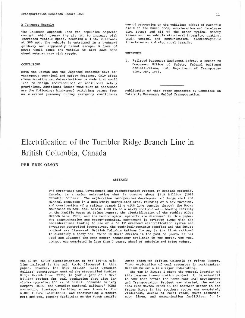
Ocean coast of British Columbia at Prince Rupert. Thus, exploration of coal resources in northeastern British Columbia is a major undertaking.
The map in Figure 1 shows the general location of this immense transportation project. It is essential to note that before the North-East Coal Development and Transportation Project was started, the entire area from Dawson Creek in the northern sector to the Fraser River in the southern sector was completely wilderness, devoid of rural roads, power transmission lines, and communication facilities. It is