High-speed mobile backhaul demonstrators - Ericsson · PDF fileHigh-speed mobile backhaul...
7
High-speed mobile backhaul demonstrators The transition to new mobile technologies calls for an increase in backhaul capacity. The initial rollout of LTE will require a capacity of 100–150Mbps. Future releases will increase this requirement to gigabits per second all the way to the cell site. Why we need high-capacity backhaul Mobile broadband has been a huge suc- cess thanks to the launch of flat-rate high-speed packet access (HSPA) ser- vices, which triggered a sharply rising demand for mobile data services. It is anticipated that this trend will contin- ue with the rollout of HSPA Evolution and 3GPP Long Term Evolution (LTE), which reduce the cost per transport- ed bit. Historically, the transition to new mobile technologies has resulted in the need for a fourfold to fivefold increase in backhaul capacity. With the rollout of LTE, this translates into an LRAN back- haul capacity of 100–150Mbps. And future releases of LTE will increase the requirement for backhaul capacity to gigabits per second (Gbps) all the way to the cell site. Fiber access is the obvious first choice of technology for any high-speed link. The capacities of point-to-point or giga- bit passive optical network (GPON) links exceed any LTE backhaul requirement so far. 4 However, microwave and copper also provide technologies for reaching Gbps capacity. High-capacity microwave links The conventional spectrum for micro- wave backhaul offers frequency bands between 6GHz and 38GHz. Each band is split into several narrow-frequency channels to ensure that the available spectrum is used most efficiently. The widest channel offers approximately 50MHz of bandwidth. Using advanced modulation formats, these bands sup- port up to 500Mbps on a single car- rier. Polarization multiplexing and multiple-input/multiple-output (MIMO) techniques may further increase spectral efficiency. Likewise, adding JONAS HANSRYD PER-ERIK ERIKSSON With increasing demand for high- capacity mobile data services and a simultaneous decline in revenue per bit, network opera- tors face the challenge of provid- ing high traffic capacity while reducing overall network costs. At the same time, profitable mi- gration needs the availability of high-capacity backhaul solutions. This article presents two high- speed technology demonstra- tors: one for microwave, a single- carrier GbE microwave link; and one for copper, a 500Mbps vectorized VDSL2 link. The mobile backhaul network pro- vides connectivity between the radio base station (RBS) site and the switch site at the edge of a transport net- work. Ericsson divides the backhaul architecture into two distinct parts (Figure 1) with separate requirements 1 : the low radio access network (LRAN) and the high radio access network (HRAN). The HRAN typically aggregates traffic from several LRAN networks using an existing fiber or microwave network, such as a metro network. The LRAN, which is frequently microwave-based, provides the last mile of connectivity for the RBS sites. The LRAN typically aggregates traffic from 10 to 100 RBS sites and feeds it into the HRAN. Owing to the large number of cell base station sites in the LRAN and the dynamic changes in the network, the LRAN must be cost-effective, sim- ple, upgradeable, flexible, and able to provide peak capacity. Globally, LRANs use multiple physical link technologies (microwave, copper, and fiber), depend- ing on operator strategy and availabili- ty at the site. 2–3 Microwave usually pro- vides the lowest total cost of ownership when no other infrastructure is avail- able at the cell site, and it is today the dominating LRAN backhaul technolo- gy. However, both fiber and copper serve as common first-mile backhaul solu- tions in many parts of the world. BOX A Terms and abbreviations 3GPP 3rd Generation Partnership Project AGW access gateway AWG American wire gauge BSC base station controller CPE customer premises equipment DSLAM DSL access multiplexer FEXT far-end crosstalk FTTC fiber to the curb GbE gigabit Ethernet GPON gigabit passive optical network HDSL high-bit-rate DSL HDSL2 enhanced HDSL HRAN high RAN HSPA high-speed packet access ITU-T International Telecommunication Union Telecommunication Standardization Sector LRAN low RAN LTE 3GPP Long Term Evolution NEXT near-end crosstalk PSD power spectral density RAN radio access network RBS radio base station RNC radio network controller SHDSL single pair HDSL TDM time-division multiplexing VDSL very-high-speed DSL xDSL DSL family 10 Ericsson rEviEw • 2 2009 Vinjett Providing high traffic capacity while reducing network costs
Transcript of High-speed mobile backhaul demonstrators - Ericsson · PDF fileHigh-speed mobile backhaul...
High-speed mobile backhaul demonstrators The transition to new mobile technologies calls for an increase in backhaul capacity. The initial rollout of LTE will require a capacity of 100–150Mbps. Future releases will increase this requirement to gigabits per second all the way to the cell site.
Why we need high-capacity backhaul Mobile broadband has been a huge suc-cess thanks to the launch of flat-rate high-speed packet access (HSPA) ser-vices, which triggered a sharply rising demand for mobile data services. It is anticipated that this trend will contin-ue with the rollout of HSPA Evolution and 3GPP Long Term Evolution (LTE), which reduce the cost per transport-ed bit.
Historically, the transition to new mobile technologies has resulted in the need for a fourfold to fivefold increase in backhaul capacity. With the rollout of LTE, this translates into an LRAN back-haul capacity of 100–150Mbps. And future releases of LTE will increase the requirement for backhaul capacity to gigabits per second (Gbps) all the way to the cell site.
Fiber access is the obvious first choice of technology for any high-speed link. The capacities of point-to-point or giga-bit passive optical network (GPON) links exceed any LTE backhaul requirement so far.4 However, microwave and copper also provide technologies for reaching Gbps capacity.
High-capacity microwave linksThe conventional spectrum for micro-wave backhaul offers frequency bands between 6GHz and 38GHz. Each band is split into several narrow-frequency channels to ensure that the available spectrum is used most efficiently. The widest channel offers approximately 50MHz of bandwidth. Using advanced modulation formats, these bands sup-port up to 500Mbps on a single car-rier. Polarization multiplexing and multiple-input/multiple-output (MIMO) techniques may further increase spectral efficiency. Likewise, adding
Jona s H a nsry d pe r-e r i K e r i K sson
With increasing demand for high-capacity mobile data services and a simultaneous decline in revenue per bit, network opera-tors face the challenge of provid-ing high traffic capacity while reducing overall network costs. At the same time, profitable mi-gration needs the availability of high-capacity backhaul solutions. This article presents two high-speed technology demonstra-tors: one for microwave, a single-carrier GbE microwave link; and one for copper, a 500Mbps vectorized VDSL2 link.
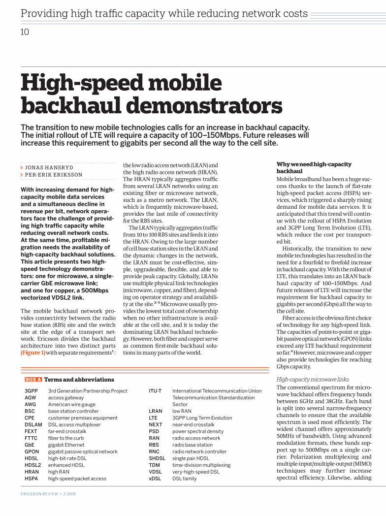
The mobile backhaul network pro-vides connectivity between the radio base station (RBS) site and the switch site at the edge of a transport net-work. Ericsson divides the backhaul architecture into two distinct parts (Figure 1) with separate requirements1 :
the low radio access network (LRAN) and the high radio access network (HRAN). The HRAN typically aggregates traffic from several LRAN networks using an existing fiber or microwave network, such as a metro network. The LRAN, which is frequently microwave-based, provides the last mile of connectivity for the RBS sites.
The LRAN typically aggregates traffic from 10 to 100 RBS sites and feeds it into the HRAN. Owing to the large number of cell base station sites in the LRAN and the dynamic changes in the network, the LRAN must be cost-effective, sim-ple, upgradeable, flexible, and able to provide peak capacity. Globally, LRANs use multiple physical link technologies (microwave, copper, and fiber), depend-ing on operator strategy and availabili-ty at the site.2–3 Microwave usually pro-vides the lowest total cost of ownership when no other infrastructure is avail-able at the cell site, and it is today the dominating LRAN backhaul technolo-gy. However, both fiber and copper serve as common first-mile backhaul solu-tions in many parts of the world.
BOX A Terms and abbreviations
3GPP 3rd Generation Partnership ProjectAGW access gatewayAWG American wire gaugeBSC base station controllerCPE customer premises equipmentDSLAM DSL access multiplexerFEXT far-end crosstalkFTTC fiber to the curbGbE gigabit EthernetGPON gigabit passive optical networkHDSL high-bit-rate DSLHDSL2 enhanced HDSLHRAN high RANHSPA high-speed packet access
ITU-T International Telecommunication Union Telecommunication Standardization SectorLRAN low RANLTE 3GPP Long Term EvolutionNEXT near-end crosstalkPSD power spectral densityRAN radio access networkRBS radio base stationRNC radio network controllerSHDSL single pair HDSLTDM time-division multiplexingVDSL very-high-speed DSL xDSL DSL family
10
E r i c s s o n r E v i E w • 2 2009
Vinjett
E r i c s s o n r E v i E w • 2 2009
Providing high traffic capacity while reducing network costs
C_209a.indd 10 09-09-15 15.18.23
channels (spectra) multiplies the capa-city.
Ericsson’s MINI-LINK node solutions already offer gigabit Ethernet (GbE) capacity using multiple channels and polarization multiplexing. For LTE back-haul, 14MHz and 28MHz channels with a more advanced modulation format are enough to manage the capacities in last-mile applications. For aggregat-ed links, 28MHz channels and above will be used.
The newly available 71–76GHz and 81–86GHz frequency bands, also referred to as the E-band, allow 10GHz bandwidth and thus the ability to sup-port Gbps capacity using simple mod-ulation formats on a single carrier. Radios on these frequency bands are suitable for fiber extensions within a fixed HRAN backhaul.
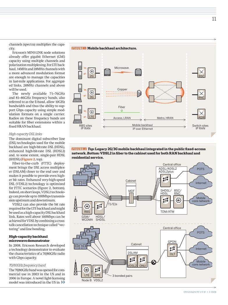
High-capacity DSL linksThe dominant digital subscriber line (DSL) technologies used for the mobile backhaul are high-bit-rate DSL (HDSL), enhanced high-bit-rate DSL (HDSL2) and, to some extent, single-pair HDSL (SHDSL) (Figure 2, top).
Fiber-to-the-curb (FTTC) deploy-ment brings the DSL access multiplex-er (DSLAM) closer to the end user and makes it possible to provide even high-er bit rates. Enhanced very-high-speed DSL (VDSL2) technology is optimized for FTTC scenarios (Figure 2, bottom). Indeed, on short loops, VDSL2 technolo-gy can provide up to 100Mbps transmis-sion upstream and downstream.
VDSL2 can also provide the bit rate required for the LTE backhaul and might be used as a high-capacity DSL backhaul link. Rates well above 100Mbps can be achieved for VDSL by combining a cross-talk cancellation technique called “vec-toring” and line bonding.
High-capacity backhaul microwave demonstratorIn 2008, Ericsson Research developed a technology demonstrator to evaluate the characteristics of a 70/80GHz radio with Gbps capacity.
70/80GHz frequency bandThe 70/80GHz band was opened for com-mercial use in 2003 in the US and in 2006 in Europe. A novel light-licensing model was introduced in the US in
O
2G
3G
LTE Access, LRAN Metro, HRAN
Mobile backhaul IP over Ethernet
Microwave
RBS sitesIP RAN
Switch sitesIP RAN
Copper
Fiber
BSC
RNC
AGW
FIGUrE 1 Mobile backhaul architecture.
GSM/WCDMA
HDSL/SHDSL
T1/E1s
Cabinet
Central officeADSL/ADSL2ADSL2plus
POTS
Internet
Mobilecore network
SHDSL/HDSL
TDM/ATM
MDF BSC/RNC
RBS
FIGUrE 2 Top: Legacy 2G/3G mobile backhaul integrated in the public fixed-access network. Bottom: VDSL2 in fiber to the cabinet used for both rAN backhaul and residential service.
Node B VDSL2
VDSL2
DSLAM
ONU
Cabinet
3 bonded pairs
Central office
POTS
Internet
Mobilecore network
OLT
GPON
LTE CPE
E r i c s s o n r E v i E w • 2 2009
Vinjett
E r i c s s o n r E v i E w • 2 2009
11
Providing high traffic capacity while reducing network costs
C_209a.indd 11 09-09-15 15.18.24
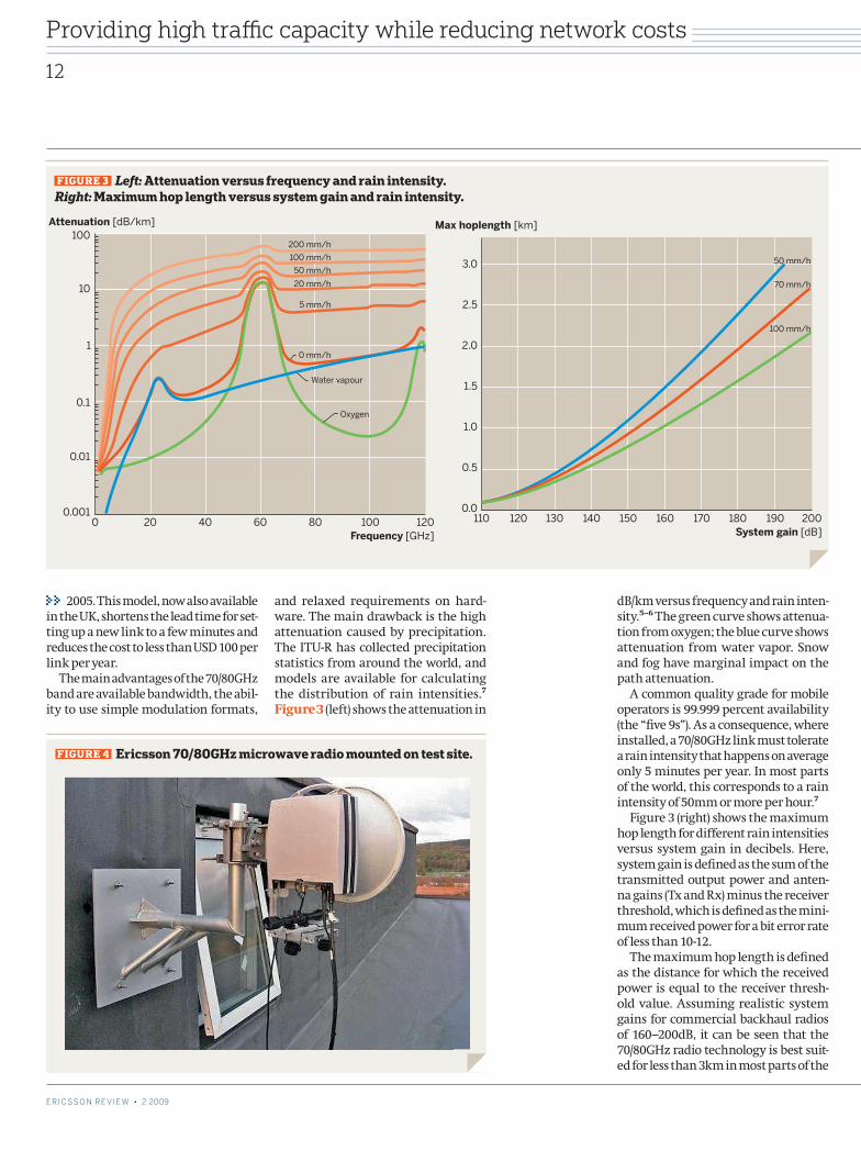
dB/km versus frequency and rain inten-sity.5–6 The green curve shows attenua-tion from oxygen; the blue curve shows attenuation from water vapor. Snow and fog have marginal impact on the path attenuation.
A common quality grade for mobile operators is 99.999 percent availability (the “five 9s”). As a consequence, where installed, a 70/80GHz link must tolerate a rain intensity that happens on average only 5 minutes per year. In most parts of the world, this corresponds to a rain intensity of 50mm or more per hour.7
Figure 3 (right) shows the maximum hop length for different rain intensities versus system gain in decibels. Here, system gain is defined as the sum of the transmitted output power and anten-na gains (Tx and Rx) minus the receiver threshold, which is defined as the mini-mum received power for a bit error rate of less than 10-12.
The maximum hop length is defined as the distance for which the received power is equal to the receiver thresh-old value. Assuming realistic system gains for commercial backhaul radios of 160–200dB, it can be seen that the 70/80GHz radio technology is best suit-ed for less than 3km in most parts of the
2005. This model, now also available in the UK, shortens the lead time for set-ting up a new link to a few minutes and reduces the cost to less than USD 100 per link per year.
The main advantages of the 70/80GHz band are available bandwidth, the abil-ity to use simple modulation formats,
and relaxed requirements on hard-ware. The main drawback is the high attenuation caused by precipitation. The ITU-R has collected precipitation statistics from around the world, and models are available for calculating the distribution of rain intensities.7 Figure 3 (left) shows the attenuation in
200 mm/h
100 mm/h
20 mm/h
50 mm/h
5 mm/h
0 mm/h
Water vapour
Oxygen
1201008060402000.001
0.01
0.1
1
10
100Attenuation [dB/km]
Frequency [GHz]
FIGUrE 3 Left: Attenuation versus frequency and rain intensity. Right: Maximum hop length versus system gain and rain intensity.
100 mm/h
70 mm/h
50 mm/h
200190180170160150140130120110
3.0
2.5
2.0
1.5
1.0
0.5
0.0
Max hoplength [km]
System gain [dB]
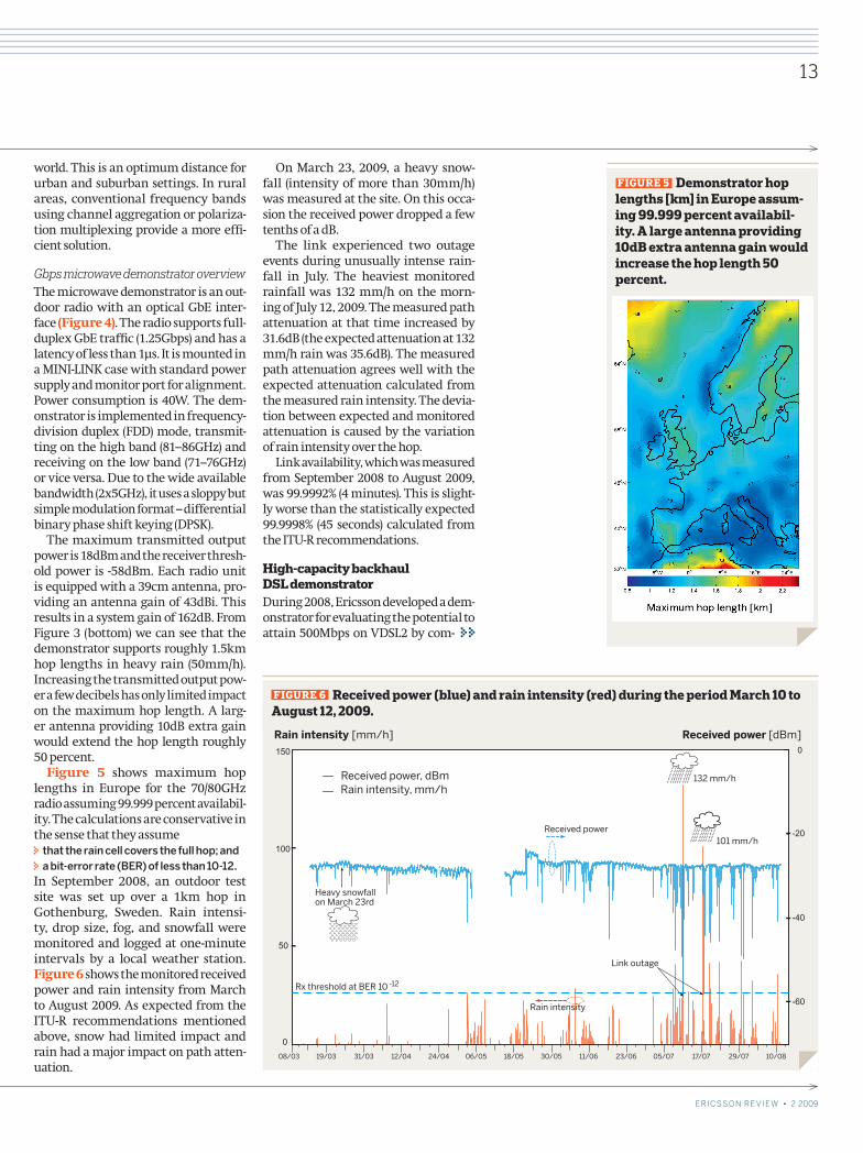
FIGUrE 4 Ericsson 70/80GHz microwave radio mounted on test site.
12
E r i c s s o n r E v i E w • 2 2009 E r i c s s o n r E v i E w • 2 2009
Providing high traffic capacity while reducing network costs
C_209a.indd 12 09-09-15 15.18.25
world. This is an optimum distance for urban and suburban settings. In rural areas, conventional frequency bands using channel aggregation or polariza-tion multiplexing provide a more effi -cient solution.
Gbps microwave demonstrator overviewThe microwave demonstrator is an out-door radio with an optical GbE inter-face (Figure 4). The radio supports full-duplex GbE traffi c (1.25Gbps) and has a latency of less than 1µs. It is mounted in a MINI-LINK case with standard power supply and monitor port for alignment. Power consumption is 40W. The dem-onstrator is implemented in frequency-division duplex (FDD) mode, transmit-ting on the high band (81–86GHz) and receiving on the low band (71–76GHz) or vice versa. Due to the wide available bandwidth (2x5GHz), it uses a sloppy but simple modulation format – differential binary phase shift keying (DPSK).
The maximum transmitted output power is 18dBm and the receiver thresh-old power is -58dBm. Each radio unit is equipped with a 39cm antenna, pro-viding an antenna gain of 43dBi. This results in a system gain of 162dB. From Figure 3 (bottom) we can see that the demonstrator supports roughly 1.5km hop lengths in heavy rain (50mm/h). Increasing the transmitted output pow-er a few decibels has only limited impact on the maximum hop length. A larg-er antenna providing 10dB extra gain would extend the hop length roughly 50 percent.
Figure 5 shows maximum hop lengths in Europe for the 70/80GHz radio assuming 99.999 percent availabil-ity. The calculations are conservative in the sense that they assume
that the rain cell covers the full hop; and a bit-error rate (BER) of less than 10-12.
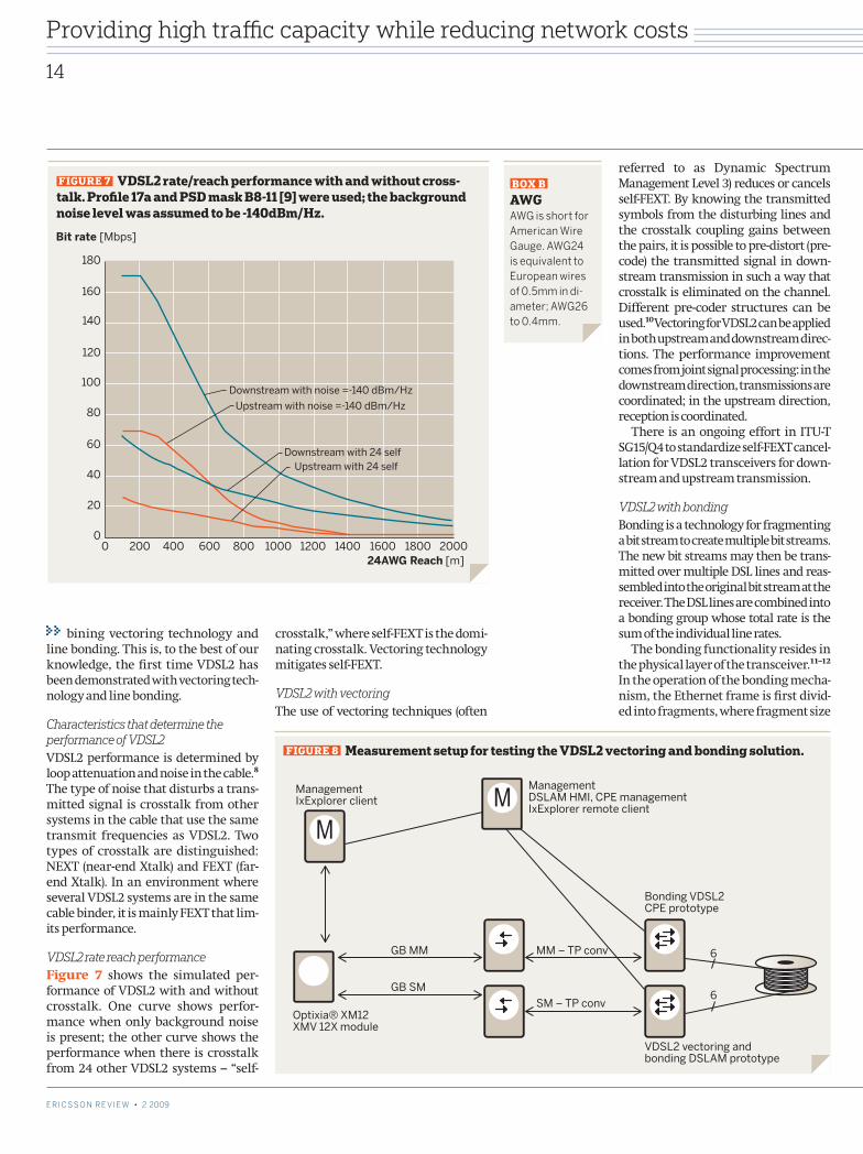
In September 2008, an outdoor test site was set up over a 1km hop in Gothenburg, Sweden. Rain intensi-ty, drop size, fog, and snowfall were monitored and logged at one-minute intervals by a local weather station. Figure 6 shows the monitored received power and rain intensity from March to August 2009. As expected from the ITU-R recommendations mentioned above, snow had limited impact and rain had a major impact on path atten-uation.
On March 23, 2009, a heavy snow-fall (intensity of more than 30mm/h) was measured at the site. On this occa-sion the received power dropped a few tenths of a dB.
The link experienced two outage events during unusually intense rain-fall in July. The heaviest monitored rainfall was 132 mm/h on the morn-ing of July 12, 2009. The measured path attenuation at that time increased by 31.6dB (the expected attenuation at 132 mm/h rain was 35.6dB). The measured path attenuation agrees well with the expected attenuation calculated from the measured rain intensity. The devia-tion between expected and monitored attenuation is caused by the variation of rain intensity over the hop.
Link availability, which was measured from September 2008 to August 2009, was 99.9992% (4 minutes). This is slight-ly worse than the statistically expected 99.9998% (45 seconds) calculated from the ITU-R recommendations.
High-capacity backhaul DSL demonstratorDuring 2008, Ericsson developed a dem-onstrator for evaluating the potential to attain 500Mbps on VDSL2 by com-
FIGUrE 5 Demonstrator hop lengths [km] in Europe assum-ing 99.999 percent availabil-ity. A large antenna providing 10dB extra antenna gain would increase the hop length 50 percent.
Received power, dBmRain intensity, mm/h
Heavy snowfall on March 23rd
Received power
132 mm/h
101 mm/h
Link outage
0
50
100
150
-60
-40
-20
0
Rx threshold at BER 10 -12
Rain intensity
Rain intensity [mm/h] Received power [dBm]
08/03 19/03 31/03 12/04 24/04 06/05 18/05 30/05 11/06 23/06 05/07 17/07 29/07 10/08
FIGUrE 6 received power (blue) and rain intensity (red) during the period March 10 to August 12, 2009.
E r i c s s o n r E v i E w • 2 2009
13
E r i c s s o n r E v i E w • 2 2009
Providing high traffi c capacity while reducing network costs
C_209a.indd 13 09-09-15 15.18.26
referred to as Dynamic Spectrum Management Level 3) reduces or cancels self-FEXT. By knowing the transmitted symbols from the disturbing lines and the crosstalk coupling gains between the pairs, it is possible to pre-distort (pre-code) the transmitted signal in down-stream transmission in such a way that crosstalk is eliminated on the channel. Different pre-coder structures can be used.10 Vectoring for VDSL2 can be applied in both upstream and downstream direc-tions. The performance improvement comes from joint signal processing: in the downstream direction, transmissions are coordinated; in the upstream direction, reception is coordinated.
There is an ongoing effort in ITU-T SG15/Q4 to standardize self-FEXT cancel-lation for VDSL2 transceivers for down-stream and upstream transmission.
VDSL2 with bondingBonding is a technology for fragmenting a bit stream to create multiple bit streams. The new bit streams may then be trans-mitted over multiple DSL lines and reas-sembled into the original bit stream at the receiver. The DSL lines are combined into a bonding group whose total rate is the sum of the individual line rates.
The bonding functionality resides in the physical layer of the transceiver.11–12 In the operation of the bonding mecha-nism, the Ethernet frame is first divid-ed into fragments, where fragment size
bining vectoring technology and line bonding. This is, to the best of our knowledge, the first time VDSL2 has been demonstrated with vectoring tech-nology and line bonding.
Characteristics that determine the performance of VDSL2VDSL2 performance is determined by loop attenuation and noise in the cable.8 The type of noise that disturbs a trans-mitted signal is crosstalk from other systems in the cable that use the same transmit frequencies as VDSL2. Two types of crosstalk are distinguished: NEXT (near-end Xtalk) and FEXT (far-end Xtalk). In an environment where several VDSL2 systems are in the same cable binder, it is mainly FEXT that lim-its performance.
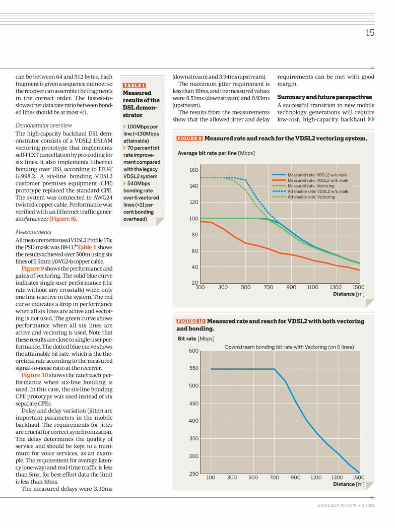
VDSL2 rate reach performanceFigure 7 shows the simulated per-formance of VDSL2 with and without crosstalk. One curve shows perfor-mance when only background noise is present; the other curve shows the performance when there is crosstalk from 24 other VDSL2 systems – “self-
crosstalk,” where self-FEXT is the domi-nating crosstalk. Vectoring technology mitigates self-FEXT.
VDSL2 with vectoringThe use of vectoring techniques (often
Downstream with noise =-140 dBm/Hz
Upstream with noise =-140 dBm/Hz
Downstream with 24 selfUpstream with 24 self
2000180016001400120010008006004002000
180
160
140
100
120
80
40
60
20
0
Bit rate [Mbps]
24AWG Reach [m]
FIGUrE 7 VDSL2 rate/reach performance with and without cross-talk. Profile 17a and PSD mask B8-11 [9] were used; the background noise level was assumed to be -140dBm/Hz.
ManagementIxExplorer client
ManagementDSLAM HMI, CPE managementIxExplorer remote client
Optixia® XM12XMV 12X module
GB MM 6
6
MM – TP conv
Bonding VDSL2CPE prototype
VDSL2 vectoring andbonding DSLAM prototype
SM – TP conv
GB SM
FIGUrE 8 Measurement setup for testing the VDSL2 vectoring and bonding solution.
BOX B AWG AWG is short for American Wire Gauge. AWG24 is equivalent to European wires of 0.5mm in di-ameter; AWG26 to 0.4mm.
14
E r i c s s o n r E v i E w • 2 2009 E r i c s s o n r E v i E w • 2 2009
Providing high traffic capacity while reducing network costs
C_209a.indd 14 09-09-15 15.18.26
can be between 64 and 512 bytes. Each fragment is given a sequence number so the receiver can assemble the fragments in the correct order. The fastest-to- slowest net data rate ratio between bond-ed lines should be at most 4:1.
Demonstrator overviewThe high-capacity backhaul DSL dem-onstrator consists of a VDSL2 DSLAM vectoring prototype that implements self-FEXT cancellation by pre-coding for six lines. It also implements Ethernet bonding over DSL according to ITU-T G.998.2. A six-line bonding VDSL2 customer premises equipment (CPE) prototype replaced the standard CPE. The system was connected to AWG24 twisted-copper cable. Performance was verified with an Ethernet traffic gener-ator/analyzer (Figure 8).
MeasurementsAll measurements used VDSL2 Profile 17a; the PSD mask was B8-11.9 Table 1 shows the results achieved over 500m using six lines of 0.5mm (AWG24) copper cable.
Figure 9 shows the performance and gains of vectoring. The solid blue curve indicates single-user performance (the rate without any crosstalk) when only one line is active in the system. The red curve indicates a drop in performance when all six lines are active and vector-ing is not used. The green curve shows performance when all six lines are active and vectoring is used. Note that these results are close to single-user per-formance. The dotted blue curve shows the attainable bit rate, which is the the-oretical rate according to the measured signal-to-noise ratio at the receiver.
Figure 10 shows the rate/reach per-formance when six-line bonding is used. In this case, the six-line bonding CPE prototype was used instead of six separate CPEs.
Delay and delay variation (jitter) are important parameters in the mobile backhaul. The requirements for jitter are crucial for correct synchronization. The delay determines the quality of service and should be kept to a mini-mum for voice services, as an exam-ple. The requirement for average laten-cy (one-way) and real-time traffic is less than 5ms; for best-effort data the limit is less than 10ms.
The measured delays were 3.30ms
(downstream) and 3.94ms (upstream).The maximum jitter requirement is
less than 10ms, and the measured values were 0.51ms (downstream) and 0.93ms (upstream).
The results from the measurements show that the allowed jitter and delay
requirements can be met with good margin.
Summary and future perspectivesA successful transition to new mobile technology generations will require low-cost, high-capacity backhaul
Average bit rate per line [Mbps]
Distance [m]
20
40
60
80
100
120
140
160
100 300 500 700 900 1100 1300 1500
Measured rate: VDSL2 w/o xtalkMeasured rate: VDSL2 with xtalkMeasured rate: VectoringAttainable rate: VDSL2 w/o xtalkAttainable rate: Vectoring
FIGUrE 9 Measured rate and reach for the VDSL2 vectoring system.
TABLE 1 Measured results of the DSL demon-strator
100Mbps per line (>130Mbps attainable)
70 percent bit rate improve-ment compared with the legacy VDSL2 system
540Mbps bonding rate over 6 vectored lines (<11 per-cent bonding overhead)
Bit rate [Mbps]
Distance [m] 100 300 500 700 900 1100 1300 1500
250
300
350
400
450
500
550
600Downstream bonding bit rate with Vectoring (on 6 lines)
FIGUrE 10 Measured rate and reach for VDSL2 with both vectoring and bonding.
E r i c s s o n r E v i E w • 2 2009
15
E r i c s s o n r E v i E w • 2 2009
Providing high traffic capacity while reducing network costs
C_209a.indd 15 09-09-15 15.18.26
solutions. Where fiber is available, the recommended choice is optical access. Where there is no fiber infra-structure, microwave and copper can be used.
As a complement to existing multi-carrier Gbps microwave solutions in tra-ditional frequency bands, the 70/80GHz band provides sufficient bandwidth to enable single-carrier Gbps microwave links. This ensures that microwave will remain a viable backhaul solution. Applications for radios on these bands currently include urban and suburban HRAN fiber-extension solutions that cover hop lengths of up to 3km.
Ericsson has presented a VDSL2 dem-onstrator with vectoring technology and line bonding. Measurements show that it is possible to attain bit rates of 500Mbps over copper loops longer than 500m. Vectoring is an efficient crosstalk cancellation technology that boosts the per-line performance in a binder.
In a fiber-deep deployment scenario, outdoor cabinets equipped with VDSL2 access multiplexers are installed in the vicinity of the RBS site with fiber con-nections leading to the aggregation network. High-capacity bonded VDSL2 links can be used if there are multi-ple copper connections to the RBS site. Point-to-point fiber (GPON) and VDSL2 support flexible capacity upgrades once the base stations are connected.
Jonas Hansryd
holds a Ph.D. in high-speed optical communica-tion from Chalmers Univer-sity of Technology,
Sweden. After finishing his doctorate in 2001, he joined CENiX Inc., now Cy-optics, in Allentown, PA, USA, for two years, developing 10Gbps and 40Gbps optical transponders. He also spent one year as a postdoctoral fellow at Cornell University, Ithaca, NY, USA, working with advanced optical modulation for-mats. Returning to Sweden, he spent four years developing link layer network applications that target the automotive industry before joining Ericsson Re-search in 2008. At Ericsson he primarily works with high-capacity microwave so-lutions.
Per-Erik Eriksson
joined Ericsson in 1989 to work with ISDN design. Today, his focus is on xDSL at Ericsson Research where he is involved in
high-speed DSL research. He is also in-volved in DSL standardization, repre-senting Ericsson in ITU-T and ETSI. Per-Erik holds an M.Sc. in electronic engineering from the Royal Institute of Technology, Stockholm.
Chundury, R.: Mobile broadband backhaul: 1. Addressing the challenge. Ericsson Review, Vol. 85(2008)3, pp. 4–9High-speed technologies for mobile backhaul. 2. Ericsson white paper. September 2008How efficient mobile backhaul and packet-3. switched GSM will help win the final coverage race. Ericsson white paper. February 2009Trojer, E., Dahlfort, S., Hood, D. and Mickelsson, 4. H.: Current and next-generation PONs: A techni-cal overview of present and future PON technolo-gy. Ericsson Review, Vol. 85(2008)2, pp. 64–69Specific attenuation model for rain for use in 5. prediction methods, RECOMMENDATION ITU-R P.838-3 Attenuation by atmospheric gases, RECOMMEN-6.
DATION ITU-R P.676–677Characteristics of precipitation for propagation 7. modeling, RECOMMENDATION ITU-R P.837-5Eriksson, P-E and Odenhammar, B.: VDSL2: Next 8. important broadband technology. Ericsson Review, Vol. 83(2006) 1, G.993.2 Very high speed digital subscriber line 9. transceivers 2 (VDSL2) Amendment 1, ITU-T, 04/2007Multiuser signal and spectra coordination for 10.
digital subscriber lines, Raphael Cendrillon, December 2004G.998.1 ATM-based multi-pair bonding, ITU-T 11.
01/2005G.998.2 Ethernet-based multi-pair bonding, 12.
ITU-T 01/2005
references
Acknowledgements
Henrik Almeida, Peter Bertelsen, Jonas Edstam, Thomas Edwall, Thomas Emanuelsson, David Giaina, Kåre Gustafsson, Anders Henriks-son, Stian Kildal, Thomas Lewin, Yinggang Li, Hans Mickelsson, Klas Rapphed and Mikael Öhberg
16
E r i c s s o n r E v i E w • 2 2009
Providing high traffic capacity while reducing network costs
C_209a.indd 16 09-09-15 15.18.26