High Speed Machining Strategies for Machining Sculptured...
16
High Speed Machining Strategies for Machining Sculptured Surfaces J. Etxeberria, J. Pérez, P. López, G. Alberdi, J.C. López, I. Etxeberria TEKNIKER Avda. Otaola, 20 20600 Eibar (Gipuzkoa) - Spain E-mail: [email protected] ABSTRACT. High Speed Machining (HSM) has been discovered as one of the most promising technology for reducing production times and to improve surface finish in the machining of precision moulds and dies. However there are several factors that are critical for a good performance: cutting tool, cutting parameters and mainly the cutting strategy used in the process. This paper will focus in this area, presenting the advances achieved in the development of new cutting strategies for HSM of hardened steels and how these strategies can improve significantly the result, both from the tool life point of view and also in the geometrical accuracy and surface finish of the machined workpiece. The results described in this paper are the proposed solutions for the HSM of real parts in hardened steels in four different mould and die application sectors like forging, stamping, injection of aluminium and plastic injection. KEY WORDS: High speed machining, Rough cutting strategies, Mould and die manufacturing.
Transcript of High Speed Machining Strategies for Machining Sculptured...
High Speed Machining Strategies forMachining Sculptured Surfaces
J. Etxeberria, J. Pérez, P. López, G. Alberdi, J.C. López,I. Etxeberria
TEKNIKERAvda. Otaola, 20
20600 Eibar (Gipuzkoa) - SpainE-mail: [email protected]
ABSTRACT. High Speed Machining (HSM) has been discovered as one of the most promisingtechnology for reducing production times and to improve surface finish in the machining ofprecision moulds and dies. However there are several factors that are critical for a goodperformance: cutting tool, cutting parameters and mainly the cutting strategy used in theprocess.
This paper will focus in this area, presenting the advances achieved in the development ofnew cutting strategies for HSM of hardened steels and how these strategies can improvesignificantly the result, both from the tool life point of view and also in the geometricalaccuracy and surface finish of the machined workpiece.
The results described in this paper are the proposed solutions for the HSM of real parts inhardened steels in four different mould and die application sectors like forging, stamping,injection of aluminium and plastic injection.
KEY WORDS: High speed machining, Rough cutting strategies, Mould and diemanufacturing.
Backward jump
To click on the title jumps backward to the session content
0. Introduction
This article intends to summarise the work done in a basque ambit project [TEK 99]by some Technological Research Centres and Universities with the directimplication of machine-tool manufacturing companies, and mould and diemanufacturers. The project, financed by the Basque Government during 3 years, hasallowed to develop the high speed process in machines of our own machine-toolsector, to machine real pieces of users and to compare them to the current processes.A technological data base about the process (cutting tools, cutting conditions,strategies, CAD/CAM, characteristics of machines) has been generated and theobjective of the formation of a wide nucleus of work teams that guaranty thegeneralised development of the high speed processes in the wide basque sector ofthe mechanical manufacturing has also been accomplished.
As a particular contribution we will mention the development of the “circular”strategy and its application to any tool trajectory, strategy that allows to carry outrough cutting operations with small diameter tools and HSM machines of limitedpower.
Finally, just to mention that with the background generated during the project, thepartners have collaborated in the edition of a monographic about high speedmachining and its applications [LOP 99].
1. Experimental set-up
The figure 1 shows the High Speed Machine employed by Tekniker. The machine,type Kondia HS 1000, is equipped with a spindle of 24000 rpm, power of 17 Kwand a maximum feed speed of 24 m/min. A similar machine has been utilised in thelaboratories of UPV. In the programme of machining tests Rambaudi and Fidia HighSpeed milling machines have also intervened, as well other milling machinesreconverted with electrospindles.
The next commercial CAD/CAM software packages have been used:
CAD EUKLID, IDEAS, INTERGRAPH, UNIGRAPHICSCAM EUKLID, WORK NC, UNIGRAPHICS, POWER MILL
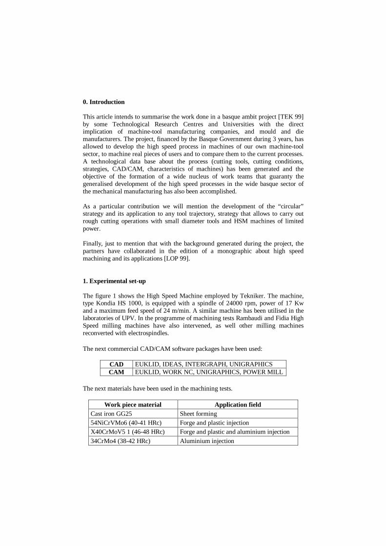
The next materials have been used in the machining tests.
Work piece material Application fieldCast iron GG25 Sheet forming54NiCrVMo6 (40-41 HRc) Forge and plastic injectionX40CrMoV5 1 (46-48 HRc) Forge and plastic and aluminium injection34CrMo4 (38-42 HRc) Aluminium injection
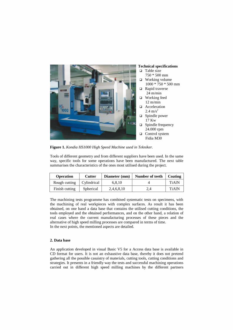
Technical specificationsq Table size 750 * 500 mmq Working volume 1000 * 750 * 500 mmq Rapid traverse 24 m/minq Working feed 12 m/minq Acceleration 2.4 m/s2
q Spindle power 17 Kwq Spindle frequency 24.000 rpmq Control system Fidia M30
Figure 1. Kondia HS1000 High Speed Machine used in Tekniker.
Tools of different geometry and from different suppliers have been used. In the sameway, specific tools for some operations have been manufactured. The next tablesummarises the characteristics of the ones most utilised during the project.
Operation Cutter Diameter (mm) Number of teeth Coating
Rough cutting Cylindrical 6,8,10 4 TiAlN
Finish cutting Spherical 2,4,6,8,10 2,4 TiAlN
The machining tests programme has combined systematic tests on specimens, withthe machining of real workpieces with complex surfaces. As result it has beenobtained, on one hand a data base that contains the utilised cutting conditions, thetools employed and the obtained performances, and on the other hand, a relation ofreal cases where the current manufacturing processes of these pieces and thealternative of high speed milling processes are compared in terms of time.In the next points, the mentioned aspects are detailed.
2. Data base
An application developed in visual Basic V5 for a Access data base is available inCD format for users. It is not an exhaustive data base, thereby it does not pretendgathering all the possible casuistry of materials, cutting tools, cutting conditions andstrategies. It presents in a friendly way the tests and successful machining operationscarried out in different high speed milling machines by the different partners
involved in the project. It pursues the objective of being useful, as starting point, forany new user of the high speed machining process. It also facilitates thepersonalisation of the software to the needs of the user.
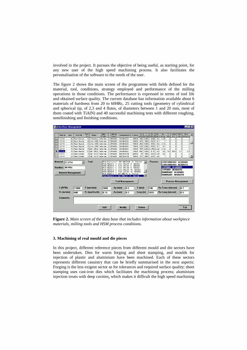
The figure 2 shows the main screen of the programme with fields defined for thematerial, tool, conditions, strategy employed and performance of the millingoperations in those conditions. The performance is expressed in terms of tool lifeand obtained surface quality. The current database has information available about 6materials of hardness from 20 to 60HRc, 25 cutting tools (geometry of cylindricaland spherical tip, of 2,3 and 4 flutes, of diameters between 1 and 20 mm, most ofthem coated with TiAlN) and 40 successful machining tests with different roughing,semifinishing and finishing conditions.
Figure 2. Main screen of the data base that includes information about workpiecematerials, milling tools and HSM process conditions.
3. Machining of real mould and die pieces
In this project, different reference pieces from different mould and die sectors havebeen undertaken. Dies for warm forging and sheet stamping, and moulds forinjection of plastic and aluminium have been machined. Each of these sectorsrepresents different casuistry that can be briefly summarised in the next aspects:Forging is the less exigent sector as for tolerances and required surface quality; sheetstamping uses cast-iron dies which facilitates the machining process; aluminiuminjection treats with deep cavities, which makes it difficult the high speed machining

process in 3 axes machines; finally the plastic injection, may be the most exigentsector as for tolerances and a good surface finishing necessities.
Different machining tests have been carried out in which it has been tried tooptimise progressively the manufacturing HSM process of the considered referencemould and dies. Likewise, an evaluation of the 4 studied cases, comparing thecurrent processes to the ones developed during the project, has been carried out.
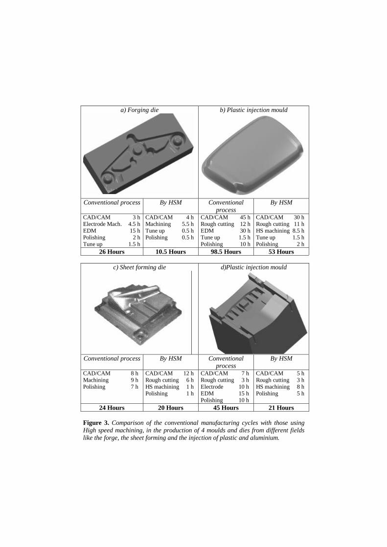
The figure 3 summarises the most significant data of the studied cases. In all of themthe advantage contributed by the high speed machining processes can be seen in anotable reduction of manufacturing time.
In all the analysed cases, a reduction of time of the cycle of manufacturing of thepiece applying high speed milling process has been observed, time reductiondepending on the characteristics of the pieces.
It is confirmed, as it is known, that the HSM processes avoid or substitute the EDMprocess, with which avoids the manufacturing of the electrode, and the EDM processitself, considered a slow manufacturing process.
The drastic reduction of polishing time is other important advantage, due to the goodsurface quality obtained with the HSM processes. We remind that the polishing,frequently, is revealed as the critical operation in the mould manufacturing.
Among the disadvantages of the HSM is identified the major CAM required time,justified by the major difficulty that presents the definition of the machiningstrategies to be employed.
Although it is not evaluated in time, another advantage that the HSM usersappreciate is that when working with treated material a lot of mould movements, fortheir heat treatment after the preliminary rough cutting operations, are eliminated.Also that the worn moulds can pass directly to be machined with a new trace,reducing in this way the time for its reuse.
a) Forging die b) Plastic injection mould
Conventional process By HSM Conventionalprocess
By HSM
CAD/CAM 3 hElectrode Mach. 4.5 hEDM 15 hPolishing 2 hTune up 1.5 h
CAD/CAM 4 hMachining 5.5 hTune up 0.5 hPolishing 0.5 h
CAD/CAM 45 hRough cutting 12 hEDM 30 hTune up 1.5 hPolishing 10 h
CAD/CAM 30 hRough cutting 11 hHS machining 8.5 hTune up 1.5 hPolishing 2 h
26 Hours 10.5 Hours 98.5 Hours 53 Hours
c) Sheet forming die d)Plastic injection mould
Conventional process By HSM Conventionalprocess
By HSM
CAD/CAM 8 hMachining 9 hPolishing 7 h
CAD/CAM 12 hRough cutting 6 hHS machining 1 hPolishing 1 h
CAD/CAM 7 hRough cutting 3 hElectrode 10 hEDM 15 hPolishing 10 h
CAD/CAM 5 hRough cutting 3 hHS machining 8 hPolishing 5 h
24 Hours 20 Hours 45 Hours 21 Hours
Figure 3. Comparison of the conventional manufacturing cycles with those usingHigh speed machining, in the production of 4 moulds and dies from different fieldslike the forge, the sheet forming and the injection of plastic and aluminium.
4. New cutting strategies
In different machine tool exhibitions [JIN 98] [MAQ 98], several high speedmachine manufacturers are offering interesting strategies that however are hardlyavailable in CAD/CAM commercial programmes. Strategies as the ones called“trochoidal” [ENH 98] or “epicicloidal” achieve to machine slots with tools ofdiameter lower than the width of the slot, with really amazing performance in termsof the metal removal rate and the tool life.
The first thing that attracts attention with these strategies is that the axial depth ofcut increases 10 or 20 times, that is, we pass from working with axial engagementsof ~0.1*D to work with values of ~1.5*D (being D the diameter of the tool).Regardless other considerations these strategies allows a more rational use of thecutting tool, no limiting this exclusively to the tip of the tool.
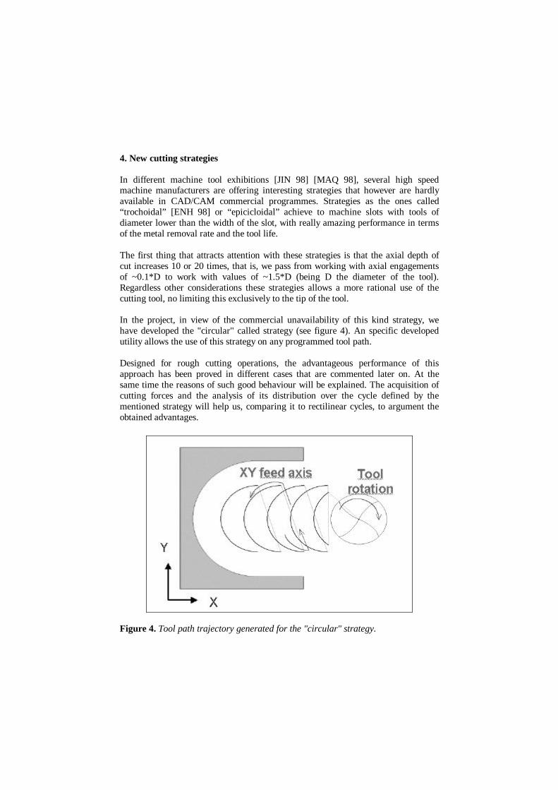
In the project, in view of the commercial unavailability of this kind strategy, wehave developed the "circular" called strategy (see figure 4). An specific developedutility allows the use of this strategy on any programmed tool path.
Designed for rough cutting operations, the advantageous performance of thisapproach has been proved in different cases that are commented later on. At thesame time the reasons of such good behaviour will be explained. The acquisition ofcutting forces and the analysis of its distribution over the cycle defined by thementioned strategy will help us, comparing it to rectilinear cycles, to argument theobtained advantages.
Figure 4. Tool path trajectory generated for the "circular" strategy.

The tool path follows a semicircular trajectory that after each cycle moves the valueof the lateral feed (Ae).
In the machining tests carried out with this trajectory, it has been noticed thatpractically the total amount of the heat generated during the cutting is eliminatedwith the chip (red-hot chip) and that the tool remains cold, which favours theprolongation of the tool life.
Respecting to a rectilinear trajectory the differences can be summarised in the nextpoints:
q The contact time tool/piece is cut practically by half, which allows its cooling.q The tool, submitted to nominal cutting forces, happens to be only during a short
moment, which represents a drastic reduction of the solicitations of the tool.
Figure 5. Evolution of cuttingforces in the orthogonaldirections X-Y of themeasuring table, during acycle of the circular tool pathtrajectory, when machining aslot of 16 mm width with a 10mm. diameter tool.(Y= tool progression axis)
Figure 6 shows the relativemagnitude of the cuttingforces of the figure 5, madehis radial (Fr) and tangentialcomponents (Ft), anddistributed on the circulartrajectory of a cycle.FR represents the resultantforceFrom the tangential force willbe extracted the Torque andconsumed spindle power.
Figure 5 shows the registered efforts with a Kistler dynamometric table in the X-Yorthogonal axis (Y: axis of the radial advance of the tool) during a machining cyclewith the circular strategy. Nominal spindle rotation and radial feed are 10.000 RPMand 4 m/min, respectively.
Intervening geometric transformation tangential and radial components arecalculated (see figure 6). It can be observed that efforts are minimum to thebeginning and end of circular trajectory and they pass by maximum values in thecentral part, position in which Ft attempt a value of 187 N. In these terms, and for adiameter of tool of 10 mm, the Torque value is 0.93 N.m. and the consumed power 1KW. Like say in the introduction, it is demonstrated that it is possible to accomplishoperations of rough cutting with little power consumption.
5. Generalisation of the circular strategy to any tool path trajectory
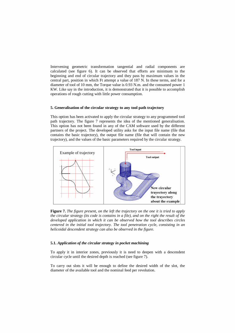
This option has been activated to apply the circular strategy to any programmed toolpath trajectory. The figure 7 represents the idea of the mentioned generalisation.This option has not been found in any of the CAM software used by the differentpartners of the project. The developed utility asks for the input file name (file thatcontains the basic trajectory), the output file name (file that will contain the newtrajectory), and the values of the basic parameters required by the circular strategy.
Example of trajectory
Figure 7. The figure present, on the left the trajectory on the one it is tried to applythe circular strategy (its code is contains in a file), and on the right the result of thedeveloped application in which it can be observed how the tool describes circlescentered in the initial tool trajectory. The tool penetration cycle, consisting in anhelicoidal descendent strategy can also be observed in the figure.
5.1. Application of the circular strategy in pocket machining
To apply it in interior zones, previously it is need to deepen with a descendentcircular cycle until the desired depth is reached (see figure 7).
To carry out slots it will be enough to define the desired width of the slot, thediameter of the available tool and the nominal feed per revolution.
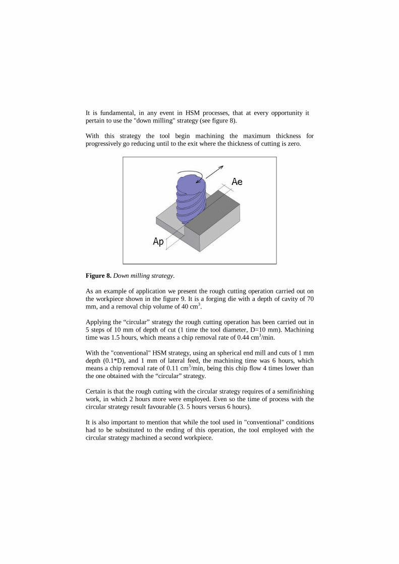
It is fundamental, in any event in HSM processes, that at every opportunity itpertain to use the "down milling" strategy (see figure 8).
With this strategy the tool begin machining the maximum thickness forprogressively go reducing until to the exit where the thickness of cutting is zero.
Figure 8. Down milling strategy.
As an example of application we present the rough cutting operation carried out onthe workpiece shown in the figure 9. It is a forging die with a depth of cavity of 70mm, and a removal chip volume of 40 cm3.
Applying the “circular” strategy the rough cutting operation has been carried out in5 steps of 10 mm of depth of cut (1 time the tool diameter, D=10 mm). Machiningtime was 1.5 hours, which means a chip removal rate of 0.44 cm3/min.
With the "conventional" HSM strategy, using an spherical end mill and cuts of 1 mmdepth (0.1*D), and 1 mm of lateral feed, the machining time was 6 hours, whichmeans a chip removal rate of 0.11 cm3/min, being this chip flow 4 times lower thanthe one obtained with the “circular” strategy.
Certain is that the rough cutting with the circular strategy requires of a semifinishingwork, in which 2 hours more were employed. Even so the time of process with thecircular strategy result favourable (3. 5 hours versus 6 hours).
It is also important to mention that while the tool used in "conventional" conditionshad to be substituted to the ending of this operation, the tool employed with thecircular strategy machined a second workpiece.
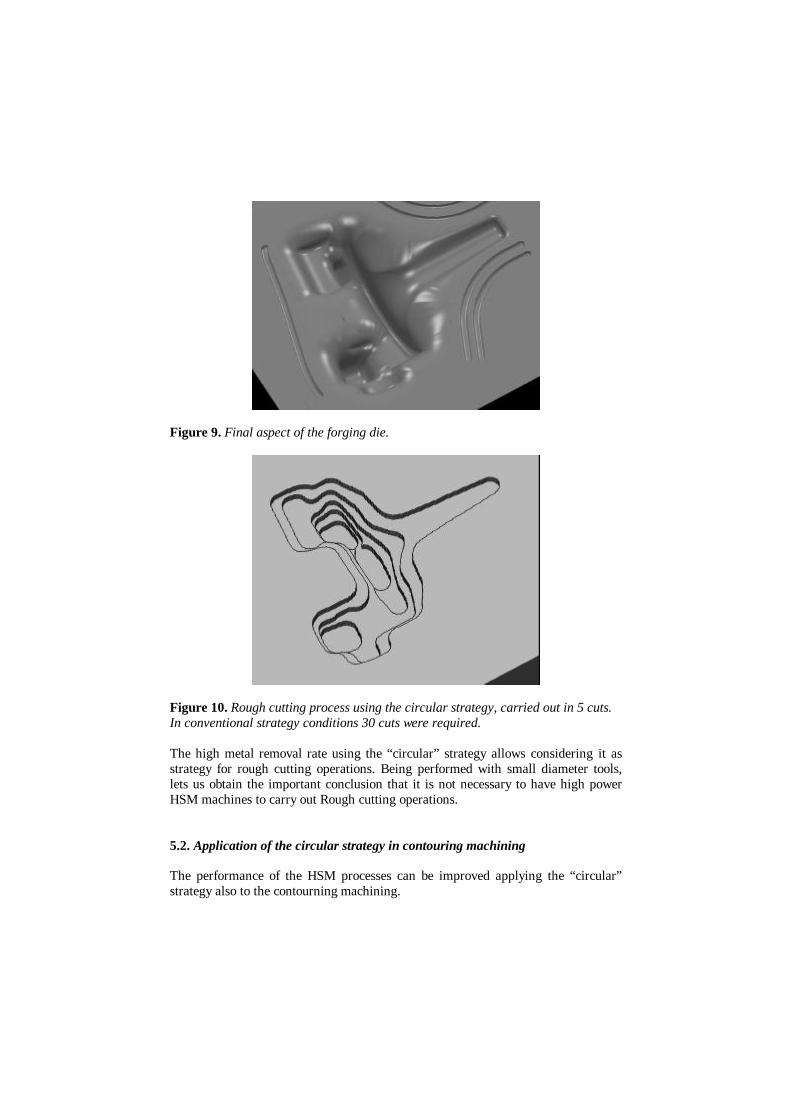
Figure 9. Final aspect of the forging die.
Figure 10. Rough cutting process using the circular strategy, carried out in 5 cuts.In conventional strategy conditions 30 cuts were required.
The high metal removal rate using the “circular” strategy allows considering it asstrategy for rough cutting operations. Being performed with small diameter tools,lets us obtain the important conclusion that it is not necessary to have high powerHSM machines to carry out Rough cutting operations.
5.2. Application of the circular strategy in contouring machining
The performance of the HSM processes can be improved applying the “circular”strategy also to the contourning machining.
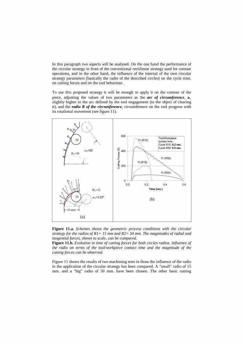
In this paragraph two aspects will be analysed. On the one hand the performance ofthe circular strategy in front of the conventional rectilinear strategy used for contouroperations, and in the other hand, the influence of the internal of the own circularstrategy parameters (basically the radio of the described circles) on the cycle time,on cutting forces and on the tool behaviour.
To use this proposed strategy it will be enough to apply it on the contour of thepiece, adjusting the values of two parameters as the arc of circumference, α,slightly higher to the arc defined by the tool engagement (to the object of clearingit), and the radio R of the circumference, circumference on the tool progress withits rotational movement (see figure 11).
R2=50
∅ 10
FtFr
α2=50
R1=15
α1=110º∅ 10
15 mm
Ft
Fr
(a)
(b)
Figure 11.a. Schemes shows the geometric process conditions with the circularstrategy for the radios of R1= 15 mm and R2= 50 mm. The magnitudes of radial andtangential forces, shown to scale, can be compared.Figure 11.b. Evolution in time of cutting forces for both circles radios. Influence ofthe radio on terms of the tool/workpiece contact time and the magnitude of thecutting forces can be observed.
Figure 11 shows the results of two machining tests in those the influence of the radioin the application of the circular strategy has been compared. A "small" radio of 15mm. and a "big" radio of 50 mm. have been chosen. The other basic cutting

parameters were: S: 10.000rpm, F: 4 m/min, depth of cut: 10 mm. and a tooldiameter: 10 mm. Workpiece material: UNE F1250 (42 HRc).
Results are summarised in the table 1:
Radio of the circular strategy: R1= 15 mm. R2= 50 mm.
Tool/piece contact time/ cycle 0.2 sec. 0.4 sec.Radial force (N):Tangential force (N):Torque (N.m.):Spindle Consumed power (Kw):
57020011
450800.40.4
Metal Removal rate: 45 mm3/cycle, the same in both cases(lateral engagement* Ae * Ap)
Machining observations: Case R=15: - Incandescent chip, cold tool,inappreciable wear of the tool.Case R=50: - Premature tool damage.Excessive tool flank wear
Table 1. Summary of the influence of the radio on the circular strategy.
For the observations during machining, we realise that it is preferable a little radio toa big radio. Priority must be given to the reduction of the tool/piece contact time,even in spite of the fact that the cutting forces grow larger.
For the same lateral feed for cycle (Ae), the thickness of cutting is minor whenprincipal is the radio (as it can be seen comparing scheme of figure 11.a or can beread from the values of cutting forces (figure 11.b)).
In these terms, enlarging the tool/piece contact time, time machining almost nothingalso increases putting the tool simply rubbing against to workpiece surface, under aconsiderable radial effort, what undoubtedly explains the exaggerated and prematuredeterioration of the cutting edges.
To emphasise that the metal removal volume do not vary with the "radio", being thisvolume calculated by the product of the lateral feed, the slot width and the depth ofcut.
Radio values lower than 2 times the diameter of the tool can be recommended. Forminimising the tool/workpiece contact time the slot width must be also limited to amaximum of 1.5 times the tool diameter.
In the following paragraphs will be mentioned the advantages shown by theapplication of the circular strategy in the "contourning" operation, comparing it withthe conventional rectilinear strategy. Figures 13 and 14 summarises used conditions

and strategies, and obtained performances in terms of cycles times and cuttingforces.
Figure 13.a. Contourning with thecircular strategy.
Figure 14.a. Conventional contourning.
CONDITIONSS:10.000 r.p.m. F: 4.000 mm/min. Ae: 0.3 mm. Ap: 10mm.
Width of the slot: 16 mm. Length of the slot: 10 mm.Contact time: 0.3 sec.Cycle time: 0.8 sec.
Machining time: 26 sec.
Contact time: 0.4 sec.Cycle time: 1.2 sec.
Machining time: 64 sec.Evolution of cutting forces during a cycle
Figure 13.b. Evolution of the cuttingforces corresponding with a cycle of the"circular" strategy.
Figure 14.b. Evolution of the cuttingforces corresponding with a cycle of the"conventional rectilinear" strategy.
From the presented example it can be concluded that removing the same chipvolume, in the application of the circular strategy a series of advantages cometogether:
- Machining time is sensitively inferior (26 seconds vs. 64 seconds), 2.5 timesfaster.
- Lower Tool/workpiece contact time (0.3 seconds vs. 0.4 seconds). This favoursthe observed cooling of the tool.
- Lower cutting forces.
It has to be added that during the machining the carried out observations confirmthat the tool works easily. It keeps colder and the chips present better aspect.
These characteristics show that the "contourning machining" with the circularstrategy is preferable because of it combines higher metal removal rates withimproved tool life.
6. Conclusions
q The realisation of the project during the last 3 years has allowed the training of 5working teams in the Basque Country in HSM processes. Likewise, 5 companiesfrom the moulds and dies sectors have been able to optimise their manufacturingprocesses identifying new manufacturing solutions.
q A database about HSM processes applied to mould and die machining has beendeveloped, and it is available, with the aim of becoming a guide for beginners ora tool adaptable to the needs of the experimented user.
q The advantageous application of HSM comparing to the conventional processeshas been demonstrated on different mould and dies (from the forging, plastic andaluminium injection sectors),
q The “circular” strategy has been developed, and applied successfully in roughcutting operations, proving its indubitable properties:q It favours the concentration of the heat generated on the chip, maintaining the
tool cold.q It allows the use of big depths of cut (till ≈ 1*D).q It reduces the machining time, increasing the metal removal rate.q By means of the reduction of the cutting forces and the tool/piece contact
time, it is favoured the tool life improvement.q The application of the circular strategy to any tool path trajectory has been
developedq Future works: the obtaining of better surface finishing and the machining in 5
axes to achieve deeper cavities, avoiding vibration problems due to an excessiveslenderness of the tools, are considered pending aspects.
7. Acknowledgements
The author wish to thank to the Industry Department of the Basque Government thefinancing of the project, without which it would not have been possible thedevelopment of the project. Last, but by no means least, I would like toacknowledge the significant contributions to all aspects of this work by the other 10partners involved in this project: Mech. Dept. of the ETSII (UPV), Mech. Dept. of

MEP University, MATRICI S. Coop., MAIER S. Coop., SFP, ALCORTABROCKHAUS S.A., KONDIA S.A., HELITOOL, IDEKO, FATRONIK.
8. References
[TEK 99] TEKNIKER, Research project: “Aplicación de los procesos de mecanizado a altavelocidad en la fabricación de moldes y matrices. Desarrollo de estrategias de mecanizado".Basque Gouvernement. Period: 1997-1999.
[LOP 99] LOPEZ DE LACALLE, N., “Fresado de alta velocidad, proceso, máquinas yaplicaciones” (Book), IMHE, ISSN: 0210-1777, Nov. 1999.
[JIN 98] JINTOF, Japanise Machine-tool Fair, Osaka, Nov. 1998.
[MAQ 98] MAQUITEK, Spanish machine Tool Fair, Nov. 1998.
[ENH 98] Trochoid Pocket Machining on horizontal Machining Center. Enhsu Corporation.www.ipnews.com\metal cutting\oct98.