High-Speed CMOS Color Stereo Camera with Low Complexity ...
5
High-Speed CMOS Color Stereo Camera with Low Complexity VLSI Implementation for Real-Time 3D Vision Applications* Juseong Lee, Mincheol Kim, Hyukmin Kwon, and Bum-Jae You Abstract— The paper presents a low complexity hardware architecture of CMOS color stereo camera for real-time 3D vision applications. To minimize the hardware complexity, two key ideas are applied. Firstly, a hardware architecture sharing line-by-line overlapped convolution kernels is proposed to reduce the number of arithmetic operations in demosaicing of bayer RGB images without image quality degradation. Secondly, an adaptive sync compensation module is proposed to synchronize master/slave image sensors, and display devices by compensating the sync signals period of slave image sensor and display devices in real-time, after monitoring varying periods of the master sync signals. In consequence, external memories such as SDRAM, that can be a considerable overhead in stereo camera implementation, is completely removed. The proposed hardware architecture is verified that the number of logic ele- ments and registers of Intel Max10 FPGA (10M16DCU324I7G) is reduced by 69% and 76% respectively comparing to demo- saicing hardware without sharing and external memory based architecture. Also, the developed stereo camera can capture full-HD stereo images at 60 FPS and/or 1920×1200p stereo images at 54 FPS. Moreover, it is more preferable in real-time 3D vision applications. I. I NTRODUCTION Many three-dimensional (3D) vision applications includ- ing visual servoing, object recognition, or tracking involve heavy usage of images from a stereo camera since it is rich with information [1]–[4]. Especially, due to the increased demand of stereo cameras with a high resolution and a high frame rate in recent 3D vision applications, very-large-scale integration (VLSI) implementation of image signal processor (ISP) is necessary to operate with low-power consumption [5]–[7]. An ISP of a stereo camera consists of color interpo- lation (demosaicing) [8], stereo image synchronization, and etc [9]. Compared to cameras with a single image sensor, computational complexity of stereo cameras is at least twice as high because an ISP of a stereo camera processes data from left and right image sensors. Therefore, it is important to carry out VLSI implementation of an area efficient ISP. One of the previous researches involves hardware im- plementation based on the architecture depicted in Figure 1 [10]. The hardware first receives raw Bayer RGB (Red, Green, and Blue) image from each image sensor through field programmable gate arrays (FPGA), then performs image pre-processing such as demosaicing. Afterwards, it performs *This research was supported by the Global Frontier Program through the National Research Foundation of Korea (NRF) funded by the Ministry of Science and ICT (NRF-2010-0029759). J. Lee, M. Kim, H. Kwon, and B.-J. You are with Center of Human- centered Interaction for Coexistence (CHIC), Seoul 02792, Korea. (e-mail: {juseong.lee, balla, hmkwon, ybj}@chic.re.kr) Image Sensor (Left) Image Sensor (Right) FPGA uProcessor (MPU) Off-chip memory (SDRAM) USB 3.0 PHY Clock / Command Sync FPGA and MPU Data Data User Applications (PC) Figure 1. Block diagram of stereo camera. synchronization between master image sensor and slave de- vices like slave image sensors and display devices using the off-chip memory, and it transfers the resulting stereo image to a personal computer (PC) that runs the user applications by using a universal serial bus (USB) 3.0 physical layer (PHY) on a microprocessor (MPU). Demosaicing process requires the implementation of a two-dimensional (2D) image filter. In previous works, researchers often had acceptably reduced hardware complexity by compromising trade-offs between image quality and computational complexity [9]. However, this approach cannot be an ultimate solution as applications still require high quality images with reduced computational complexity. Stereo cameras undergo two synchronization processes: stereo image and sensor – display synchroniza- tion. In the past, researchers carried out these synchronization processes by designing a synchronization module using an external memory such as synchronous dynamic random- access memory (SDRAM) [10]. However, external memory- based synchronization approaches often results in expensive hardware cost for the external memory and the memory con- troller. Moreover, external memory has a narrow bandwidth and low transmission speed. This can become a problem in most stereo camera synchronization approaches, since it is difficult to meet the throughput requirements of the high performance stereo camera. In this paper, there is shown a low complexity and high- speed CMOS (Complementary Metal-Oxide-Semiconductor) color stereo camera that can capture 60 frames of full-high definition (HD) and/or 54 frames of 1920×1200p stereo images per second. Firstly, there is proposed a area efficient hardware architecture that can share the hardware resources line-by-line overlapped convolution kernels in demosaicing of bayer RGB images without image quality degradation. Also, a low hardware complexity adaptive sync compensa- tion module is proposed to synchronize stereo image sensors and display devices by compensating the sync signals period of slave image sensor and display devices in real-time, after monitoring varying periods of the master sync signals.
Transcript of High-Speed CMOS Color Stereo Camera with Low Complexity ...

High-Speed CMOS Color Stereo Camera with Low ComplexityVLSI Implementation for Real-Time 3D Vision Applications*
Juseong Lee, Mincheol Kim, Hyukmin Kwon, and Bum-Jae You
Abstract— The paper presents a low complexity hardwarearchitecture of CMOS color stereo camera for real-time 3Dvision applications. To minimize the hardware complexity,two key ideas are applied. Firstly, a hardware architecturesharing line-by-line overlapped convolution kernels is proposedto reduce the number of arithmetic operations in demosaicingof bayer RGB images without image quality degradation.Secondly, an adaptive sync compensation module is proposed tosynchronize master/slave image sensors, and display devices bycompensating the sync signals period of slave image sensor anddisplay devices in real-time, after monitoring varying periodsof the master sync signals. In consequence, external memoriessuch as SDRAM, that can be a considerable overhead in stereocamera implementation, is completely removed. The proposedhardware architecture is verified that the number of logic ele-ments and registers of Intel Max10 FPGA (10M16DCU324I7G)is reduced by 69% and 76% respectively comparing to demo-saicing hardware without sharing and external memory basedarchitecture. Also, the developed stereo camera can capturefull-HD stereo images at 60 FPS and/or 1920×1200p stereoimages at 54 FPS. Moreover, it is more preferable in real-time3D vision applications.
I. INTRODUCTION
Many three-dimensional (3D) vision applications includ-ing visual servoing, object recognition, or tracking involveheavy usage of images from a stereo camera since it is richwith information [1]–[4]. Especially, due to the increaseddemand of stereo cameras with a high resolution and a highframe rate in recent 3D vision applications, very-large-scaleintegration (VLSI) implementation of image signal processor(ISP) is necessary to operate with low-power consumption[5]–[7]. An ISP of a stereo camera consists of color interpo-lation (demosaicing) [8], stereo image synchronization, andetc [9]. Compared to cameras with a single image sensor,computational complexity of stereo cameras is at least twiceas high because an ISP of a stereo camera processes datafrom left and right image sensors. Therefore, it is importantto carry out VLSI implementation of an area efficient ISP.
One of the previous researches involves hardware im-plementation based on the architecture depicted in Figure1 [10]. The hardware first receives raw Bayer RGB (Red,Green, and Blue) image from each image sensor throughfield programmable gate arrays (FPGA), then performs imagepre-processing such as demosaicing. Afterwards, it performs
*This research was supported by the Global Frontier Program throughthe National Research Foundation of Korea (NRF) funded by the Ministryof Science and ICT (NRF-2010-0029759).
J. Lee, M. Kim, H. Kwon, and B.-J. You are with Center of Human-centered Interaction for Coexistence (CHIC), Seoul 02792, Korea. (e-mail:{juseong.lee, balla, hmkwon, ybj}@chic.re.kr)
Image Sensor
(Left)
Image Sensor
(Right)
FPGA
uProcessor
(MPU)
Off-chip
memory
(SDRAM)
USB 3.0
PHY
Clock /
CommandSync
FPGA and MPU
Data
Data
User
Applications
(PC)
Figure 1. Block diagram of stereo camera.
synchronization between master image sensor and slave de-vices like slave image sensors and display devices using theoff-chip memory, and it transfers the resulting stereo imageto a personal computer (PC) that runs the user applications byusing a universal serial bus (USB) 3.0 physical layer (PHY)on a microprocessor (MPU). Demosaicing process requiresthe implementation of a two-dimensional (2D) image filter.In previous works, researchers often had acceptably reducedhardware complexity by compromising trade-offs betweenimage quality and computational complexity [9]. However,this approach cannot be an ultimate solution as applicationsstill require high quality images with reduced computationalcomplexity. Stereo cameras undergo two synchronizationprocesses: stereo image and sensor – display synchroniza-tion. In the past, researchers carried out these synchronizationprocesses by designing a synchronization module using anexternal memory such as synchronous dynamic random-access memory (SDRAM) [10]. However, external memory-based synchronization approaches often results in expensivehardware cost for the external memory and the memory con-troller. Moreover, external memory has a narrow bandwidthand low transmission speed. This can become a problemin most stereo camera synchronization approaches, since itis difficult to meet the throughput requirements of the highperformance stereo camera.
In this paper, there is shown a low complexity and high-speed CMOS (Complementary Metal-Oxide-Semiconductor)color stereo camera that can capture 60 frames of full-highdefinition (HD) and/or 54 frames of 1920×1200p stereoimages per second. Firstly, there is proposed a area efficienthardware architecture that can share the hardware resourcesline-by-line overlapped convolution kernels in demosaicingof bayer RGB images without image quality degradation.Also, a low hardware complexity adaptive sync compensa-tion module is proposed to synchronize stereo image sensorsand display devices by compensating the sync signals periodof slave image sensor and display devices in real-time,after monitoring varying periods of the master sync signals.

This approach does not use an external memory, therebyreducing hardware complexity while achieving guaranteedsynchronization accuracy.
The rest of the paper is organized as follows. Section IIreviews related works of the stereo camera. Proposed areaefficient stereo camera is presented in section III. Hardwarearchitecture and experimental results are described in sectionIV. Finally, conclusion is drawn in section V.
II. RELATED WORKS
A. Demosaicing Process for Bayer Pattern to RGB Image
Demosaicing is a color interpolation process that convertsthe raw Bayer pattern captured by the image sensor toan RGB color image. For hardware implementation of thedemosaicing module, hardware architecture of a 2D finiteimpulse response (FIR) filter is used with high complexitycoefficients [5]–[7]. Some researchers suggested to reducethe size of the image filter convolution kernel (CK) orto simplify the filter coefficients in order to curtail thecomputational complexity of the Demosaicing module [9].Since this approach does not consider the image quality,considerable degradation in image quality could occur in theworst-case scenario.
B. Stereo Image and Sensor-Display Device Synchronization
A stereo camera system includes capturing time synchro-nization of left/right stereo image sensors and image sensor –display synchronization to remove an sense of abnormality instereo images. For the stereo image sensor synchronization,some approached with an external clock sharing method [10].This method however bears a problem because of differentlatencies due to the process variation of an image sensor inproducing the image data output. For reliable synchronizationof stereo image sensors, external memory was used in [10].Since required external memory size is proportional to theimage resolution generated by the image sensor, for stereocameras with high resolution image sensors it increasessignificantly. In addition, high performance external memorycontroller is necessary to run higher frame rate which furthercomplicates the hardware complexity. Therefore, some imagesensors come with a slave mode that takes master syncsignals such as horizontal and vertical sync signals as aninput [11]. But in order to optimize the synchronizationaccuracy of a stereo image sensor, it needs sync signals thatare timing guaranteed. For stable data transmission from thecamera to a PC that runs the user application, an externalmemory is used for synchronization between image sensorsand display devices [10]. Since it uses an external memoryfor stereo image sensor synchronization as well, expensivehardware cost is also a problem.
III. PROPOSED LOW COMPLEXITY STEREO CAMERA
In this section, we introduce our key approaches to mini-mizing the hardware complexity of the stereo camera. In Sec-tion A, a high performance demosaicing filter based on thehardware resources sharing method is, and in B, an adaptive
G B G B G B G
R G R G R G R
G B G B G B G
R G R G R G R
G B G B G B G
R G R G R G R
G B G B G B G
R G R G R G R
G B G B G B G
R G R G R G R
G B G B G B G
R G R G R G R
G B G B G B G
R G R G R G R
G B G B G B G
R G R G R G R
G B G B G B G
R G R G R G R
G B G B G B G
R G R G R G R
G B G B G B G
R G R G R G R
G B G B G B G
R G R G R G R
-1 -1
-1 4 5 4 -1
-1 -1
-1
-1 4 -1
5
-1 4 -1
-1
0.5
0.5
0.5 0.5
2 2
5
2 2
-1
2
2
2-1 4 -1
2
-1
-1.5
-1.5 -1.5
-1.5
2 2
5
2 2
-1
2
2
2-1 4 -1
2
-1
-1.5
-1.5 -1.5
-1.5
-1 -1
-1 4 5 4 -1
-1 -1
-1
-1 4 -1
5
-1 4 -1
-1
0.5
0.5
0.5 0.5
CK(Red)
CK(Blue)
CK(Red)
CK(Green) CK(Blue) CK(Blue)
CK(Red)CK(Green)
Demosaicing Procedure Demosaicing Procedure Demosaicing Procedure Demosaicing Procedure
(a) (b) (c) (d)Figure 2. Demosaicing procedure and its convolution kernel (CK).(a) R and B at G locations in B row, R column. (b) R and G at B
locations in B row, B column. (c) G and B at R locations in R row, Rcolumn. (d) R and B at G locations in R row, B column.
stereo camera synchronization method is described in details.Comparison results are also shown for fair evaluation.
A. Low Complexity and High Performance Demosaicingbased on Hardware Resource Sharing Technique
In the proposed demosaicing hardware architecture, hard-ware complexity can be reduced by overlapped convolutionkernels sharing line-by-line.
Figure 2 shows the demosaicing procedure and convolu-tion kernel in each case, respectively. Image sensor processesraw Bayer image data from top to bottom, from left to right.In terms of the image sensor operation, demosaicing for Gand B locations are consecutively processed as shown inFigure 2(a), (b), and R and B locations are consecutivelyprocessed as in Figure 2(c), (d). This means for a Full-HD resolution, i.e. 1920×1080, intervals between each rowinclude at least 1920 clock cycles. In addition, for theconvolution kernel of demosaicing [8] shown in Figure 2, onecan see the filter coefficients completely overlaps between Rand B at G locations (Figure 2(a)) and B and R at R locations(Figure 2(d)), and also between R and G at B locations(Figure 2(b)) and B and G at R locations (Figure 2(c)). Thisfact can be utilized to reduce the hardware complexity forarithmetic operations by sharing the demosaicing hardwarefor the overlapping convolution kernels based on the timeinterval characteristic of the image rows.
Moreover, computational complexity required for demo-saicing is further reduced by adopting computation resultsreutilization based on convolution kernel rank characteristic[7]. For instance, in the convolution kernel of R in Figure2(a), weighted sum of the two coefficients (1) in the 2nd
column can be used to decrease the number of arithmeticoperations necessary to acquire the weighted sum of thetwo coefficients (4) in the 3rd column and that of the twocoefficients (1) in the 4th column [7]. Likewise, hardwarecomplexity required for the implementation of Figure 2(b),(c), and (d) can be reduced in a similar way.

TABLE I. COMPUTATIONAL COST COMPARISON OF DEMOSAICING.
Direct 2DFiltering [6]
ComputationReuse [7]
ProposedSharing
Approach
Number ofArithmetic (A)
72AAdd.
+ 80AMult.
62AAdd.
+ 64AMult.
31AAdd.
+ 32AMult.
When high performance 5×5 demosaicing convolution kernel [8] is applied.
Time (Hours)
1 2 3 4 5 6 7 8 9 10 11 122183
2184
2185
2186
2187
2188
2189
2190
2191
2192
2193
cn
ys
H fo
se
ula
V tn
uo
C le
xiP
Figure 3. Master Hsync signal variation analysis.
Computational cost comparisons for various demosaicingare presented in Table I. The computational complexity ofthe proposed demosaicing is reduced by almost half of theresults by the architecture shown in [7] as can be seen.
B. Adaptive Stereo Camera Synchronization Approach
For the stereo image and sensor – display device syn-chronization, it is crucial to monitor the exact period of thesync signals of the image sensor. As resolution and framerate of the image sensor increase, it is more probable forthe sync signal variation enlarges as well. Figure 3 showsthe results of horizontal sync (Hsync) variation analysisusing the image sensor in [11], which has a pixel clockfrequency of 148.5MHz, Hsync period of 2200 clock cycles,and vertical sync (Vsync) period of 1125 times Hsync. Inorder to measure the amount of variation, we implementeda counter in FPGA and measured the average count valuesover a Hsync period of the image sensor in [11]. As can beseen in Figure 3, there was an average of 15 clock cycles ofvariation. Even if an image sensor can run on a slave mode,if the master image sensor has a variation in the sync signals,stereo camera cannot operate precisely. For this reason, anexternal memory is used in a high resolution and frame ratestereo camera for the stereo camera synchronization [10].
The proposed stereo camera synchronization approachminimizes the hardware complexity by applying real-timesync signals monitoring and compensation. This approachmonitors the Hsync maximum variation of master modeimage sensor during each Vsync period and modifies thefront and back porch of the Hsync to be transferred to
CK for R at G &B at G
CK for B at G & R at G
CK for R at B &B at R
CK for G at B & G at R
Vsync Counter
Line Buffers
10
R B
10
B R
10
R B
10
G G
LS
B o
f Vs
yn
c
Figure 4. Proposed demosaicing hardware architecture.
the slave mode image sensor and the display device. Fol-lowing are procedures of the proposed sync monitoringand compensation module.: 1) The period of sync signalsfrom the master image sensor is used to set the referencevalue for the pixel counter, 2) the period of the masterHsync is measured using the counter, and 3) calculates thevariation using the reference and measured count values.4) Steps (2∼3) are iterated during one period of Vsyncand calculate the maximum variation and, 5) Front porchand back porch of Hsync are modified according to themaximum variation value. The proposed sync monitoringand compensation module effectively optimizes the hardwarecomplexity required for the synchronization process in ahigh-performance image sensor. The performance of theproposed method is depicted in the subsection B of SectionIV via hardware implementation.
IV. VLSI IMPLEMENTATION WITH NUMERICAL RESULTS
In this section, experiment results from FPGA-based VLSIimplementation of the demosaicing and adaptive stereo syn-chronization hardware architecture are shown and discussed.In addition, VLSI implementation results with the overallarchitecture of stereo camera that has been applied proposedhardware blocks. In order to show the hardware cost re-duction more clearly, we have compared the logic elements,registers, and the memory size necessary to run Max10 IntelFPGA (10M16DCU324I7G) [13] and Quartus Prime LiteEdition v17.0.
A. Computation Sharing Demosaicing Architecture
Figure 4 depicts the hardware architecture of proposeddemosaicing module. The hardware is composed of linebuffers and arithmetic operators for 2D convolution. If theindex of an image row is even, convolution kernel (CK)coefficients of Figure 2(a), (b), or of Figure 2(c), (d) ifodd, are used as image filter coefficients using the Vsynccounter value and the multiplexer in order to make hardwaresharing possible. To minimize the hardware area, we havealso implemented computation re-use approach [7]. For themultiplier required for the weighted sums, shifter and adderare used to optimize the area consumption as they areconstant coefficients.
Table II shows the implementation results of previousworks [6], [7], and the proposed demosaicing hardware. As
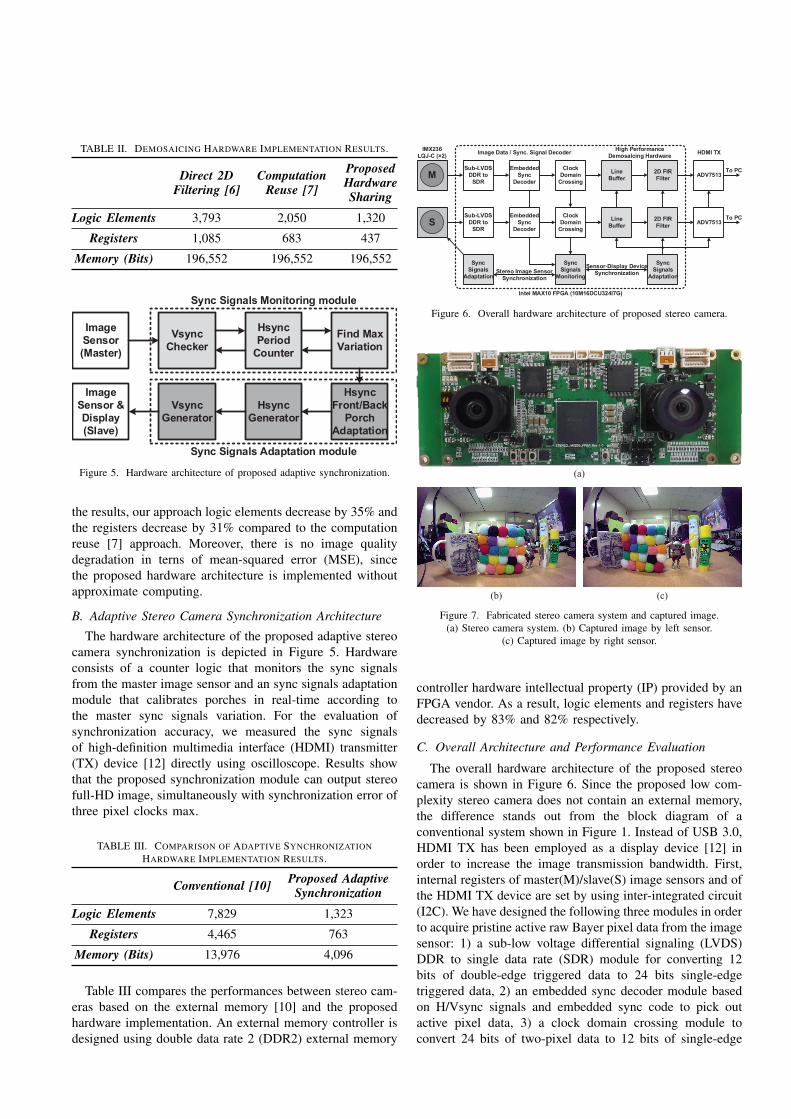
TABLE II. DEMOSAICING HARDWARE IMPLEMENTATION RESULTS.
Direct 2DFiltering [6]
ComputationReuse [7]
ProposedHardwareSharing
Logic Elements 3,793 2,050 1,320
Registers 1,085 683 437
Memory (Bits) 196,552 196,552 196,552
Image
Sensor
(Master)
Vsync
Checker
Hsync
Period
Counter
Find Max
Variation
Hsync
Front/Back
Porch
Adaptation
Hsync
Generator
Vsync
Generator
Image
Sensor &
Display
(Slave)
Sync Signals Monitoring module
Sync Signals Adaptation module
Figure 5. Hardware architecture of proposed adaptive synchronization.
the results, our approach logic elements decrease by 35% andthe registers decrease by 31% compared to the computationreuse [7] approach. Moreover, there is no image qualitydegradation in terns of mean-squared error (MSE), sincethe proposed hardware architecture is implemented withoutapproximate computing.
B. Adaptive Stereo Camera Synchronization Architecture
The hardware architecture of the proposed adaptive stereocamera synchronization is depicted in Figure 5. Hardwareconsists of a counter logic that monitors the sync signalsfrom the master image sensor and an sync signals adaptationmodule that calibrates porches in real-time according tothe master sync signals variation. For the evaluation ofsynchronization accuracy, we measured the sync signalsof high-definition multimedia interface (HDMI) transmitter(TX) device [12] directly using oscilloscope. Results showthat the proposed synchronization module can output stereofull-HD image, simultaneously with synchronization error ofthree pixel clocks max.
TABLE III. COMPARISON OF ADAPTIVE SYNCHRONIZATIONHARDWARE IMPLEMENTATION RESULTS.
Conventional [10] Proposed AdaptiveSynchronization
Logic Elements 7,829 1,323
Registers 4,465 763
Memory (Bits) 13,976 4,096
Table III compares the performances between stereo cam-eras based on the external memory [10] and the proposedhardware implementation. An external memory controller isdesigned using double data rate 2 (DDR2) external memory
IMX236
LQJ-C (×2)
MSub-LVDS
DDR to
SDR
Sub-LVDS
DDR to
SDR
Embedded
Sync
Decoder
Clock
Domain
Crossing
Clock
Domain
Crossing
Line
Buffer
2D FIR
Filter
2D FIR
Filter
ADV7513
S
Image Data / Sync. Signal DecoderHigh Performance
Demosaicing HardwareHDMI TX
Sync
Signals
Monitoring
Embedded
Sync
Decoder
Sync
Signals
Adaptation
Line
BufferADV7513
Sensor-Display Device
Synchronization
Sync
Signals
AdaptationStereo Image Sensor
Synchronization
To PC
To PC
Intel MAX10 FPGA (10M16DCU324I7G)
Figure 6. Overall hardware architecture of proposed stereo camera.
(a)
(b) (c)
Figure 7. Fabricated stereo camera system and captured image.(a) Stereo camera system. (b) Captured image by left sensor.
(c) Captured image by right sensor.
controller hardware intellectual property (IP) provided by anFPGA vendor. As a result, logic elements and registers havedecreased by 83% and 82% respectively.
C. Overall Architecture and Performance Evaluation
The overall hardware architecture of the proposed stereocamera is shown in Figure 6. Since the proposed low com-plexity stereo camera does not contain an external memory,the difference stands out from the block diagram of aconventional system shown in Figure 1. Instead of USB 3.0,HDMI TX has been employed as a display device [12] inorder to increase the image transmission bandwidth. First,internal registers of master(M)/slave(S) image sensors and ofthe HDMI TX device are set by using inter-integrated circuit(I2C). We have designed the following three modules in orderto acquire pristine active raw Bayer pixel data from the imagesensor: 1) a sub-low voltage differential signaling (LVDS)DDR to single data rate (SDR) module for converting 12bits of double-edge triggered data to 24 bits single-edgetriggered data, 2) an embedded sync decoder module basedon H/Vsync signals and embedded sync code to pick outactive pixel data, 3) a clock domain crossing module toconvert 24 bits of two-pixel data to 12 bits of single-edge

TABLE IV. COMPARISON OF FPGA IMPLEMENTATION RESULTS.
Conventional[14]
[7], [10] basedArchitecture
ProposedHardware
Architecture
Logic Elements N/A 9,929 3,055
Registers N/A 5,574 1,328
Memory (Bits) N/A 211,528 196,552
Resolution 1920×1080×2 1920×1080×2 1920×1080×2
Frame rate 30 FPS 30 FPS 60 FPS
triggered data using dual-port static-random access memory(SRAM). After, active raw Bayer pixel data is taken as aninput to the demosaicing module and gets converted intoan RGB color image. At the same time sync signals fromthe master image sensor is input to the master sync signalsmonitoring module to generate the sync signals for the inputto the slave image sensor and display devices. After thestereo sensor synchronization, demosacing results from themaster sensor are saved in first in, first out (FIFO) bufferduring the little latency required for the slave sensor togenerate the color image. Finally, synchronized master andslave image data are continuously generated by using an syncsignals adaptation module and the HDMI TX device. Otherthan the image sensor [11] and the HDMI TX device [12], allmodules have been implemented with FPGA, and thus one-chip implementation was possible. Figure 7 depicts a realphoto of the stereo camera and the captured stereo imageusing OPR-HD200 [15]. Various algorithms such as colorcorrection, auto white balance, and so on, have been appliedto enhance image quality. Table IV shows the numericalresults of the proposed low complexity stereo camera. UsingFPGA, the maximum operating frequency is 165 MHz, whilethe number of logic elements and registers are reduced by69% and 76%, respectively. Whereas stereo cameras in themarket capture 30 frames per second (FPS) at Full-HDresolution [10], [14], the proposed low complexity Full-HDstereo image captures 60 FPS as the results show.
Figure 8 presents comparison between proposed stereocamera and full-HD 30 FPS stereo camera with commercialISP [16]. With twice the number of frames, it reduces motionblur when compared to 30 FPS stereo camera as shown indashed circle.
V. CONCLUSION
In this paper, a hardware architecture of a low complexitystereo camera is proposed. We proposed demosaicing andadaptive stereo camera synchronization modules without theuse of an external memory with low hardware complexitywhich successfully reduces the hardware cost of the stereocamera. Considerable hardware complexity reduction led tobetter numerical results of the hardware implementation. Theproposed stereo camera can capture 60 frames of full-HDstereo image per second. This makes it preferable in real-time 3D vision applications as higher resolution and fasterFPS are more and more in demand for complex tasks.
(a) (b)
Figure 8. Motion blur comparison. (a) Proposed 60 FPS stereo camera.(b) 30 FPS stereo camera with commercial ISP.
REFERENCES
[1] C. Cai, N. Somani, and A. Knoll, “Orthogonal Image Features forVisual Servoing of a 6-DOF Manipulator With Uncalibrated StereoCameras,” IEEE Transactions on Robotics, vol. 32, no. 2, pp. 452-461, Apr. 2016.
[2] A. Wagner, J. Wright, A. Ganesh, Z. Zhou, H. Mobahi, and Y. Ma,“Toward a Practical Face Recognition System: Robust Alignment andIllumination by Sparse Representation,” IEEE Transactions on PatternAnalysis and Machine Intelligence, vol. 34, no. 2, pp. 372-386, Feb.2012.
[3] J. Lu, Y. P. Tan, and G. Wang, “Discriminative Multimanifold Analysisfor Face Recognition from a Single Training Sample per Person,” IEEETransactions on Pattern Analysis and Machine Intelligence, vol. 35,no. 1, pp. 39-51, Jan. 2013.
[4] M. D. Breitenstein, F. Reichlin, B. Leibe, E. Koller-Meier, and L.Van Gool, “Online Multiperson Tracking-by-Detection from a Single,Uncalibrated Camera,” IEEE Transactions on Pattern Analysis andMachine Intelligence, vol. 33, no. 9, pp. 1820-1833, Sep. 2011.
[5] W.-M. Chao, L.-G. Chen, “Pyramid Architecture for 3840 X 2160Quad Full High Definition 30 Frame/s Video Acquisition,” IEEETransactions on Circuits and Systems for Video Technology, vol. 20,no. 11, pp. 1499-1508, Nov. 2010.
[6] F.-C. Huang, S.-Y. Huang, J.-W. Ker, and Y.-C. Chen, “High-Performance SIFT Hardware Accelerator for Real-Time Image FeatureExtraction,” IEEE Transactions on Circuits and Systems for VideoTechnology, vol. 22, no. 3, pp. 340-351, Mar. 2012.
[7] J. Lee, H. Tang, and J. Park, “Energy Efficient Canny Edge Detectorfor Advanced Mobile Vision Applications,” IEEE Transactions onCircuits and Systems for Video Technology, vol. 28, no. 4, pp. 1037-1046, Apr. 2018.
[8] Malvar, H.S., L. He, and R. Cutler, “High Quality Linear Interpolationfor Demosaicing of Bayer-patterned Color Images,” IEEE ICASSP,vol. 34, no. 11, pp. 2274-2284, May. 2004.
[9] W. Jin, G. He, W. He, and Z. Mao, “A 12-bit 1928 × 3264 pixelCMOS image signal processor for digital still cameras,” Integration,the VLSI Journal, vol. 59, pp. 206-217, Sep. 2017.
[10] OVRVISION PRO, [Online]. Available: http://ovrvision.com/pro-dev-report-on-sep2015-en/
[11] IMX236LQJ-C datasheet, Rev1.1-2014.01.20, Sony Corporation, 1-7-1 Konan, Minato-ku, Tokyo, 108-0075, Japan.
[12] ADV7513 datasheet, Rev. B-2012.03, Analog Devices Inc., OneTechnology Way, P.O. Box 9106, Norwood, MA 02062-9106, U.S.A.
[13] Intel MAX10 FPGA device datasheet, M10-DATASHEET-2017.12.15,Intel Programmable Solutions Group (PSG), 101 Innovation Drive SanJose, CA 95134, U.S.A.
[14] ZED Stereo camera, [Online]. Available: https://www.stereolabs.com/zed/
[15] OPR-HD200, [Online]. Available: http://www.oupree.com/Pro-Capture-Dual-HDMI-Video-Capture-Card.html/
[16] NVP2421 datasheet, Rev0.2-2012.Nov.21, Nextchip, Venture ForumBldg, 323, Pangyoro, Bundang-gu, Seongnam-si, Gyeonggi-do, 463-400, Korea.