High Speed Air Turbine Handpiece - Brasseler...
16
OPERATION MANUAL High Speed Air Turbine Handpiece Please read this Operation Manual carefully before use and file for future reference. Handpiece should not be used with friction grip burs exceeding 18.5 mm in length.
Transcript of High Speed Air Turbine Handpiece - Brasseler...

OP
ER
ATIO
N M
AN
UA
L
High Speed Air Turbine Handpiece
Please read this Operation Manual carefully before use and �le for future reference.Handpiece should not be used with friction grip burs exceeding 18.5 mm in length.
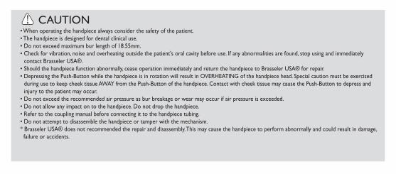
CAUTION• When operating the handpiece always consider the safety of the patient.• The handpiece is designed for dental clinical use.• Do not exceed maximum bur length of 18.55mm.• Check for vibration, noise and overheating outside the patient's oral cavity before use. If any abnormalities are found, stop using and immediately
contact Brasseler USA®.• Should the handpiece function abnormally, cease operation immediately and return the handpiece to Brasseler USA® for repair.• Depressing the Push-Button while the handpiece is in rotation will result in OVERHEATING of the handpiece head. Special caution must be exercised
during use to keep cheek tissue AWAY from the Push-Button of the handpiece. Contact with cheek tissue may cause the Push-Button to depress and injury to the patient may occur.
• Do not exceed the recommended air pressure as bur breakage or wear may occur if air pressure is exceeded.• Do not allow any impact on to the handpiece. Do not drop the handpiece.• Refer to the coupling manual before connecting it to the handpiece tubing.• Do not attempt to disassemble the handpiece or tamper with the mechanism.* Brasseler USA® does not recommended the repair and disassembly. This may cause the handpiece to perform abnormally and could result in damage,
failure or accidents.
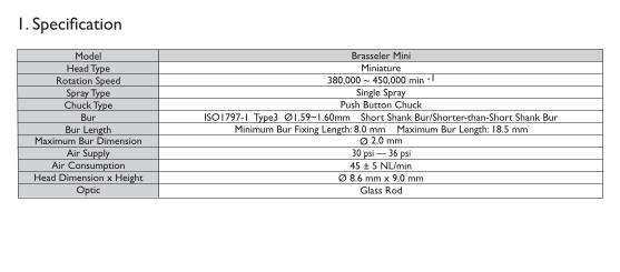
1. Speci�cation
ModelHead Type
Rotation SpeedSpray TypeChuck Type
BurBur Length
Air SupplyAir Consumption
Head Dimension x HeightOptic
Brasseler MiniMiniature
380,000 ~ 450,000 min -1Single Spray
Push Button ChuckISO1797-1 Type3 Ø1.59~1.60mm Short Shank Bur/Shorter-than-Short Shank Bur
Ø 8.6 mm x 9.0 mm45 ± 5 NL/min
Minimum Bur Fixing Length: 8.0 mm Maximum Bur Length: 18.5 mmMaximum Bur Dimension Ø 2.0 mm
30 psi — 36 psi
Glass Rod

CAUTION• Do not use non-standard burs. The ISO standard shank diameter is Ø1.5.9-Ø1.60mm• Fully depress the Push Button and insert the bur into the chuck until bur is secure.• Do not use bur when removing the crown, do not use bur to pry loose the crown. It may cause a malfunction in the handpiece.• Do not apply too much pressure to the bur. Bur may break or bend and become difficult to remove. • Do not use any bur longer than 18.5mm.• Do not use bent, worn, damaged, or non-concentric burs. Such burs can cause damage to the handpiece.• Do not exceed the bur speed recommended by the bur manufacturer.• Always use clean burs. Unclean burs may allow debris to build up inside chuck, causing weak bur retention or premature chuck wear.• When using shorter-than-short burs make certain the head/diamonds do not come in contact with the chucking mechanism.
2. Caution on burs
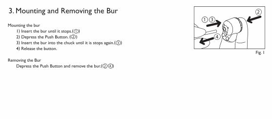
3. Mounting and Removing the Bur
Mounting the bur1) Insert the bur until it stops.( )2) Depress the Push Button. ( )3) Insert the bur into the chuck until it is stops again.( )4) Release the button.
Removing the BurDepress the Push Button and remove the bur.( )
Fig. 1
4
231
4
2
3
12
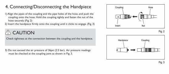
4. Connecting/Disconnecting the Handpiece
Check tightness at the connection between the coupling and the handpiece.
Hose Coupling
Insert Nut
Handpiece Coupling
Fig. 3
Fig. 2
3) Do not exceed the air pressure of 36psi (2.5 bar). Air pressure readings must be checked at the coupling joint as shown in Fig. 3.
1) Align the pipes of the coupling and the pipe holes of the hose, and push the coupling onto the hose. Hold the coupling tightly and fasten the nut of the hose securely. (Fig. 2)
2) Insert the handpiece �rmly onto the coupling until it clicks to engage. (Fig. 3)
CAUTION

5. Lubrication
• Hold the spray can upright.
• Be sure to hold the handpiece firmly to prevent the handpiece from slipping out of hand by the spray pressure when lubricating.
• Supply lubricant until it comes out of the handpiece head (for approx. 2-3 seconds).
SPRAYSPRAY
Spray Nozzle Handpiece
Supply spray after each use (after cleaning the holes) and/or before autoclaving.
1) Push spray nozzle attachment over the SPRAY can nozzle until it firmly seats.
2) Insert the spray nozzle in the rear of the handpiece and spray for approximately 2-3 seconds.
Fig. 4
CAUTION

6. Chuck CleaningPerform the cleaning of the chuck once a week for Push Button Chuck (FG bur).
Chuck Cleaning Method1) Mount the arrow-head spray nozzle tip into the spray port.2) Lubricate chuck directly through the hole where the bur is inserted.
Fig. 5
Nozzle Tip
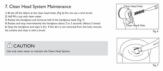
1) Brush off the debris at the clean head holes. (Fig. 6) Do not use a wire brush.2) Half �ll a cup with clean water.3) Rotate the handpiece and immerse half of the handpiece head. (Fig. 7)4) Rotate and stop intermittently the handpiece about 2 to 3 seconds. (About 3 times)6) Stop the handpiece and wipe it dry. If the dirt is not removed from the hole, remove the turbine and clean it with a brush. Fig. 6
Clean Head Hole
Clean Head HoleClean Head Hole
CAUTIONUse only clean water to maintain the Clean Head System.
Fig. 7
7. Clean Head System Maintenance
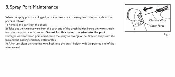
8. Spray Port Maintenance
When the spray ports are clogged, or spray does not exit evenly from the ports, clean the ports as follows:1) Remove the bur from the chuck. 2) Take out the cleaning wire from the back end of the brush holder. Insert the wire straight into the spray ports with caution. Do not forcibly insert the wire into the port. Damaged or disoriented port could cause the spray to diverge or be directed away from the bur, and the cooling ef�ciency deteriorates. 3) After use, clean the cleaning wire. Push into the brush holder with the pointed end of the wire inward.
Fig. 8
Cleaning Wire
Spray Ports

Wipe the Glass Rod clean (Fig. 9) with an alcohol-immersed cotton swab. Remove all debris and oil.
CAUTIONDo not use a sharp tool to clean the cellular glass optic rod. It could damage the glass and reduce the light transmission. If illumination becomes dim please contact Brasseler USA®.
Cotton Swab
Fig. 9
Glass Rod
9. Fiber Optic Maintenance

10. Sterilization
CAUTION• Do not heat or cool the handpiece quickly. Rapid change in temperature could break the cellular glass rod or cause abnormal strain to
other metal components.
• Do not wash, soak, or wipe off the handpiece with oxidizing solutions (strong acid, superacid solution) or sterilizing solution.
Autoclave sterilization is recommended.
Autoclave sterilization required first time you use and after each patient (after lubrication) as noted below.
Autoclave Procedure1) Scrub dirt and debris from the handpiece, and wipe clean with alcohol-immersed cotton swab or cloth. Do not use a wire brush.
2) Lubricate with spray.
3) Insert into an autoclave pouch. Seal the pouch.
4 )Autoclavable up to a max. 275°F (135°C). ex.) Autoclave for 20 min. at 250°F (121°C) or 15 min. at 270°F (132°C).
5) Keep the handpiece in the autoclave pouch to keep it clean until you use it.
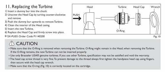
11. Replacing the Turbine
CAUTION• Make sure that the O-Ring is removed when removing the Turbine. O-Ring might remain in the Head, when removing the Turbine.
If the O-Ring remains, the new Turbine can not be inserted properly.• Use only Brasseler USA® genuine turbines. If you use other Turbine, specification may not be satisfied and void the warranty.• The head cap screw thread is very fine. To prevent damage to the thread always first tighten the handpiece head cap using fingers,
then secure with the head cap wrench.• Make sure that the O-ring (Fig. 10) is correctly located on the cartridge.
1) Insert a dummy bur into the chuck.2) Unscrew the Head Cap by turning counter-clockwise
and remove.3) Push the dummy bur upwards to remove Turbine.4) Clean the interior of the Head casing.5) Insert the new Turbine. 6) Replace the Head Cap and firmly screw into place.
SX-PU03: Order Code P1140200 Fig. 10
WrenchTurbine Head CapHead
O-Ring
PUSH
O-Ring
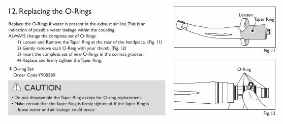
12. Replacing the O-RingsReplace the O-Rings if water is present in the exhaust air line. This is an indication of possible water leakage within the coupling. ALWAYS change the complete set of O-Rings.
1) Loosen and Remove the Taper Ring at the rear of the handpiece. (Fig. 11) 2) Gently remove each O-Ring with your thumb. (Fig. 12)3) Insert the complete set of new O-Rings in the correct grooves.4) Replace and �rmly tighten the Taper Ring.
Loosen
Fig. 11
Fig. 12
Taper Ring
O-ring Set: Order Code Y900580
CAUTION• Do not disassemble the Taper Ring except for O-ring replacement.• Make certain that the Taper Ring is firmly tightened. If the Taper Ring is loose water and air leakage could occur.

13. Replacing Non-Retraction ValveA Non-Retraction Valve is equipped in the Coupling Joint, which shuts off the water retraction right at the handpiece head, to prevent oral �uids from being sucked into the water line.
Brasseler USA® Coupling
Remove the back-end Gasket. Pull and remove the water tube, and replace the Non-Retraction Valve.
Fig. 13
Water Tube Non-Retraction Valve
Gasket

By Your Sidein Dentistry
One Brasseler Boulevard, Savannah, GA 31419To order call 800.841.4522
or fax 888.610.1937.Visit our website: www.BrasselerUSA.com