High pressure pumps for technical water type PAHT
14
danfoss.high-pressurepumps.com High pressure pumps for technical water type PAHT 521B1056 / DKCFN.PD.012.A6.02 Datasheet
Transcript of High pressure pumps for technical water type PAHT

danfoss.high-pressurepumps.com
High pressure pumps for technical watertype PAHT
521B1056 / DKCFN.PD.012.A6.02
Datasheet

Datasheet High Pressure Pumps for technical water, type PAHT
2 521B1056 / DKCFN.PD.012.A6.02 / 12.2011
Generally
Benefits
Application examples
The Danfoss High-Pressure water pumps are specifically designed for operation on technical water. Nine pump sizes with displacements from 20 to 256 ccm/rev are available providing flow in the range from 9-282 l/min. (2-74 GPM)
The axial piston principle provides very high efficiency, small and compact design and long service life.The Danfoss pumps are water lubricated and do not involve any other lubricant making this unique pump maintenance free over its entire service life.
• Maintenancefreeduetowaterlubricationanddirectdrive(nobeltorgearbox)• Veryhighefficiencycomparedtoanyotherpumponthemarket• Small,compactandlightdesign• Negligiblepressurepulsation,noneedforpulsationdampeners• Extremerecirculationcapabilitywithoutoverheating(upto90%flowat20o C)• Widespeedcontrolrange• StainlesssteeldesignAISI316(W.No.1.4401).• Fulfilsmoststringenthygienerequirements,i.e.VDI6022,HACCP• Suitableforbothboostedinletpressureandwatersupplyfromatank• AvailableasATEXcertified• CanbepoweredbyaCombustianengine• 3.2approvalsavailableaccordingtoEN10204(ABS,Lloydsorecostumerrequest)
• Adiabaticcoolingsystems• Dustsuppressionandodourcontrolsystems• Turbineindustry: -Inletfogging -Wetcompression - NOx-control - Fire suppression - Compressor wash• NOx-control in Diesel engines• High-pressurecleaningfunctionswithDI/ROwater

Datasheet High Pressure Pumps for technical water, type PAHT
3 521B1056 / DKCFN.PD.012.A6.02 / 12.2011
Code numbers
Technical data
Flow
ForATEXapprovedpumpcodenumbers,pleasecontactDanfossHigh-PressurePumpssalesdept.
* At 80 bar (1160 psi)
• Theoreticalflow: Q(th) [l/min] = pump displacement in cm3 × rpm/1000 • Flowatmax.pressure: Theflowatmax.pressureQ(pmax) is shown in the ”Techincal
data” table • Flowatanypressure: AtzeropressurethetrueflowequalsthetheoreticalflowQ(th).• Theflow(Qeff)atlessthanmax. pressure (pmax) can be calculated withthefollowingequation: Qeff=Q(th)–[(Q(th)–Q(p max)) × ( p / pmax )]
Pump size 20 25 32 50 63 70 80 90 256
Geometric displacement cm3/rev 20 25 32 50 63 70 80 90 256
Max. continuous
discharge pressurebar/psi 80/1160 160/2320 160/2320 80/1160 160/2320 160/2320 160/2320 160/2320 120/1740
Min. speed rpm 700 700 700 700 700 700 700 700 450
Max. speed rpm 2400 2400 2400 1800 1800 1800 1800 1800 1250
Typicalflowat:
450 rpm @ 120 bar
1250 rpm @ 120 bar
-
l/min
NA
23
NA
27,8
NA
37,5
NA
57,2
NA
69,25
NA
79
NA
91
NA
103,6
78
282
700 rpm @ 160 bar
1500 rpm @ 160 bar l/min
12,3*
27,7*
13,2
33,4
18,5
45,0
28,6*
68,7*
32,4
83,1
39,0
95,2
44,8
109,2
52,3
124,3
NA
NA
450 rpm @ 1740 psi
1250 rpm @ 1740 psi
GPM NA
6,0
NA
7,34
NA
9,9
NA
15,1
NA
18,3
NA
20
NA
24
NA
27,4
20,6
74,5
900rpm@2320psi
1800rpm@2320psi GPM
4,2*
9,0*
4,8
10,8
6,6
14,3
10,2*
22,1*
11,9
27,0
14,0
30,7
16,1
35,2
18,6
40,0
NA
NA
Typicalmotorsize:
at max. pressure @ 980 rpm
at max. pressure @ 1180 rpm
at max. pressure @1500 rpm
at max. pressure @ 1800 rpm
kW
HP
kW
HP
3
5,5
5,5*
7,5*
7,5
15
11
18
11
15
15
18
7,5
15
15*
18*
18,5
30
30
48
22
30
30
48
30
40
37
60
30
50
45
73
55
100
NA
NA
Weight kg/lb 19/42 19/42 19/42 34/75 34/75 34/75 34/75 34/75 105
PAHT 20 180B0019PAHT 25 180B0020PAHT32 180B0021PAHT 50 180B0085PAHT63 180B0086PAHT 70 180B0087 PAHT 80 180B0088PAHT 90 180B0089
PAHT 256 180B1001

Datasheet High Pressure Pumps for technical water, type PAHT
4521B1056 / DKCFN.PD.012.A6.02 / 12.2011
Flow curve @max pressure
02468
101214161820222426283032343638404244464850525456586062646668707274767880
400500
600700
800900
10001100
12001300
14001500
16001700
18001900
20002100
22002300
24002500
[RPM]
[GPM
]
PAHT 20PAHT 25PAHT32PAHT 50PAHT63PAHT 70PAHT 80PAHT 90PAHT 256
Pump flows gallons/min.
Pump flows litres/min.
Flow curve @max pressure
0102030405060708090
100110120130140150160170180190200210220230240250260270280290300
400500
600700
800900
10001100
12001300
14001500
16001700
18001900
20002100
22002300
24002500
[RPM]
[L/m
in]
PAHT 20PAHT 25PAHT32PAHT 50PAHT63PAHT 70PAHT 80PAHT 90PAHT 256

Datasheet High Pressure Pumps for technical water, type PAHT
5521B1056 / DKCFN.PD.012.A6.02 / 12.2011
Motor dimensioning
Operation conditions,PAHT 20-90
Operation conditions,PAHT 256
Requiredmotorpower:From the following table you can determine the rpm of the pump at the desired flow. Calculateasfollows: Speed[inrpm]× displacement per rev [in ccm] × pressure [in bar]P[inkW]=––––––––––––––––––––––––––––––––––––––––––––––––––––––– 600.000 × η mech (mechanical efficiency)
Therequiredtorqueiscalculatedasfollows: Displacement [in ccm] × pressure [in bar]M [in Nm] = –––––––––––––––––––––––––––––––––– 62.8 × η mech (mechanical efficiency)
To determine the correct motor size, both the power and torque requirement must be verified.
Themechanicalefficiencyofthepumpisestimatedasfollows:
Inletpressure:PAHT 20-90 is designed to operate under boosted pressure supply conditions. The boost pressure is to bebetween3-6bar(43-87psi)(4-7bar(58-87psi)abs).Please make use of the integrated 1/4” gauge ports (inlet) with appropriate pressure switches for monitoring the supply pressure accordingly.
Floaded suction must always be made from a tank placed above the pump min. inlet pressure is 0 bar atm.IncaseofdoubtpleasecontactDanfossHigh-PressurePumpssalesorganization.
The maximum inlet peak pressure is 15 bar (290psi).Ifitisunknownwhatthepeakinletpressurecanbe,thenthereshouldbea10bar(145psi)safetyrelief valve on the inlet side of the pump.
Temperature:Watertemperature:• Min.+3°C/37.4°F,max.50°C/122°Fatmax.dischargepressure
Ambienttemperature:• Min.0°C/32°Ftomax.50°C/122°F
Storagetemperature:• Min.-40°C/-40°Ftomax.70°C/158°F(withfactoryantifreezepreservation)
Inletpressure:PAHT 256 is designed to operate under boosted pressure supply conditions. The boost pressure is to bebetween3-6bar(43-87psi)(4-7bar(58-87psi)abs).Please make use of the integrated 1/4” gauge ports (inlet) with appropriate pressure switches for monitoring the supply pressure accordingly.
IncaseofdoubtpleasecontactDanfossHigh-PressurePumpssalesorganization.
The maximum inlet peak pressure is 15 bar (290psi).Ifitisunknownwhatthepeakinletpressurecanbe,thenthereshouldbea10bar(145psi)safetyrelief valve on the inlet side of the pump.
Temperature:Watertemperature:• Min.+3°C/37.4°F,max.50°C/122°Fatmax.dischargepressure
Ambienttemperature:• Min.0°C/32°Ftomax.50°C/122°F
Storagetemperature:• Min.-40°C/-40°Ftomax.70°C/158°F(withfactoryantifreezepreservation)
PAHT20,25,32,50,63,70,80,90 0.95
PAHT 256 0,95

Datasheet High Pressure Pumps for technical water, type PAHT
6 521B1056 / DKCFN.PD.012.A6.02 / 12.2011
Noise level
Filtration
Technical water
Corrosion and antifreezeprotection
Corrosion protection
Sincethepumptypicallyismountedonabellhousingorframe,thenoiselevelcanonlybedetermi-ned for the complete unit (system). Itisthereforeveryimportantthatthepumpismountedcorrectlyonaframewithdamperstomini-mize vibrations and noise. Furthermore the pump discharge should be connected with the application ie with a flexible high-pressure hose.
Thenoiselevelisinfluencedby:• Thespeedofthepump,highrpmcreatemorenoisethanlowrpm• Thedischargepressure,highpressuregeneratesmorenoisethanlowpressure• Rigidmountingofthepumpgeneratesmorenoisethanflexiblemounting• Pipemountingdirecttothepumpincreasesthenoiselevelcomparedtoaflexiblehose
The water must be filtered through a 10 μm absolute filter with a β10-value > 5000 (or better).For further filter details, please contact the Danfoss High-Pressure Pump sales organization.
Technicalwatermaybedividedinto3groups:
• Softenedwater(cationexchanged).• Demineralizedwater (Demineralized/de-ionized water)• Waterprocessedaccordingtothereverseosmosisprinciple(RO-water)
Softened*anddemineralized*waterarenottobeusedfordrinkingwaterinmostEuropeancountriesas the chemicals used for the processes are harmful/hazardous to human beings .
*only applying to units being regenerative.
Descriptions of the specific processes are always enclosed with the systems for making softened, demineralized and reverse osmosis-water.
WhenusingotherfluidslikeHFA,HFCetc.,please contact Danfoss High-Pressure Pump sales organization.
Ifthepumpisexposedtotemperaturesbelowfreezing,itmustbeprotectedagainstfreezing.SeealsoparagraphonOperation Conditions.
DanfossrecommendsDOWCALNorCHILLSAFEantifreezesbothbeingabiologicallydegradableMono Propylene Glycol.
(DOWCALNisproducedbyPOLO).(CHILLSAFEisproducedbyATCO).
ProducersofDOWCALNandCHILLSAFErecommendamixtureratioofmin.30%DOWCALN/CHILLS-AFEtopreventbiofilmoccurrenceinthesystemduetoDOWCALNandCHILLSAFEbeingbiologicallyde-gradable.
Ifthesystemisdecommissionedformorethan4weeksorintransportation,thepumpmustbepre-served against corrosion. Never just drain the pump!
Seeinstructionsdeliveredwiththepump

Datasheet High Pressure Pumps for technical water, type PAHT
7521B1056 / DKCFN.PD.012.A6.02 / 12.2011
Service
Installation to direct water supply, PAHT 20-256
Installation to tank supply,PAHT 20-90
The PAHT pumps are maintenance free over their entire service life. To achieve the maximum service life, proper water supply and filtration are mandatory.
Maintenance:Danfoss recommends a visual and auditory observation on regular intervals.After 8.000 hours of operation it is recommended to inspect the pump and change any worn parts, e.g. pistons and shaft seal.This is done in order to prevent a potential breakdown of the pump.
Standstill:Thepumpsaremadeofmaterialswithexcellentcorrosionproperties.Itishowever,alwaysrecommen-dedtoactivatethepumpifithasbeeninactivemorethan30days.
The pump is fed with water direct from the water supply or from a booster pump.Werecommendtousea2barpressureswitchattheinlettoensurepropersupply.
(Thenumbers1-3refertothedrawingbelow)Inordertoeliminatetheriskofcavitation,alwaysensureaminimum inlet pressure of 0 bar (0 psi) (1 bar (14,5 psi) abs), byobservingthefollowingguidelines:
1) Place the tank above the pump (water level in the tank should always be above the pump).
2) Place the inlet filter before the tank.
3) Dimensiontheinletlinetoobtainminimumpressureloss(largeflowarea,minimumpipelength,minimum number of bends/connections, fittings with small pressure losses).
In
Out
In
Out
[M]

Datasheet High Pressure Pumps for technical water, type PAHT
8 521B1056 / DKCFN.PD.012.A6.02 / 12.2011
Direction of rotation
Motor connection
Tank
The pump must not be exposed to axial nor radial loads. Wethereforerecommendtheuseofaflexiblecouplingfor connection to an electric motor or a combustion engine.
Below figure illustrates how to mount the pump and connect it to electric motor/combustion engine.
A: FlexiblecouplingB: BellhousingC: Motorshaft
Ifanalternativemountingisrequired,pleasecontactDanfoss High-Pressure Pumps sales organization for further information.
To ensure easy mounting of the flexible coupling without using tools, the tolerances must be dimen-sioned accordingly.
Make sure to observe the recommended mounting tolerances for the flexible coupling used, as any axial load on the shaft must be avoided.Danfossoffersbellhousingandcoupling-kits.PleasecontacttheDanfossHigh-PressurePumpssalesorganization.
The function of the water tank is to continuously supply clean water, divert heat, remove air and to allow for variations of the water volume.
Minimum tank capacity is dimensioned according to the volume required for water cooling, and for water expansion. Normally, a tank capacity of >0,7 times the pump flow (per min.) will be sufficient as long as there is awaterrenewalof>15%ofthepumpflow.
Direct the suction line to the pump bottom, approx. 1.5 times the suction line diameter “D” above the bottom to prevent precipitated impurities from being sucked in. Always keep all tank connections (suction, drain and return) below water level in the tank. Drain and return lines to be placed as far from the suction line as possible and preferably separated by a dividing plate in the tank. Additionally, the suction, drain, and return lines must be cutata45°angle(seeexample)
CW(clockwise)

Datasheet High Pressure Pumps for technical water, type PAHT
9 521B1056 / DKCFN.PD.012.A6.02 / 12.2011
Operation, PAH 20-256 Start-up: The system has to be flushed prior to start–up to remove possible impurities from pipes, hoses etc.
Beforestartingthepump,thetopbleedingplug”C”isloosened.Whenwaterappearsfromthebleeding plug, the pump is filled with water, and the plug is retightened. Make sure that rotation direc-tion of the pump is correct.
Withitssuctionlineconnectedtothewatersupplyorthetank,thepumpisnowstartedwithopenoutlet port.At the initial start of the system, the pump should be run without pressure for about 5 minutes to remove possible impurities from pipes, hoses, etc.
Systemsmustbeflushedwithwaterformin.30minutes(pleaseseeInstructionsfor”CleaningofWaterHydraulicSystems”).Whentheflushingiscompletedthefilterelementmustbechanged.
Safeguarding of pump during operation:Whenrunning,thepumpmustalwaysbeconnectedtothewatersupplytopreventthepumpfromrunning dry.
Insystemswithwatertankitisrecommendedtobuildinalevelgaugewhichwillmakethepumpstopat too low water level.
Ifitisunknownwhatthepeakinletpressurecanbe,thenthereshouldbea10bar(218psi)safetyrelief valve on the inlet side of the pump.
For all systems it is recommended to install a temperature gauge for stopping the pump when the watertemperatureexceeds50°C/122°F.
Filter:After start-up it is recommended to change filter element after 1-10 hours’ operation. The filter element must be changed when ”clogged filter” is indicated = too low pressure after the filter.
Disconnection:Iftheinletlinetothepumpportisdisconnectedfromthewatersupply,thepumpwillbeemptiedofwater.Beforestartingthepumpagain,thestartingproceduredescribedintheStart-up-paragraphmustbefollowed.
Transport and storage precautionsIfemptiedofwater,thesystemmustbeprotectedagainstcorrosionwithaglycolmixture(minimum35%monopropyleneglycol).The protection must be made within 2 days after the emptying.
Ifthereisriskofexposuretotemperaturesbelowthefreezingpointduringtransportorstorage,thesystemlikewisehastobeflushedwithaglycolmixture(minimum35%monopropyleneglycol).
For further information on anti-freeze media, please contact Danfoss High-Pressure Pumps sales orga-nization.
Recommended procedure:1. Disconnect the water supply to the pump/system.2. Emptythepumpthroughthelowerbleedingplug.Retightentheplugwhenthepumpisempty.3. Connectthepumptoatankwithanti-freezeadditive.ConnectahosetothepumpP-portandthe
other end of the hose back to tank. 4. Quicklystartandstopthepump.Makesurethatthepumpdoesnotrundry.5. Emptypumpofanti-freezemedium(throughthelowerbleedingplug). Remountandretightenthebleedingplug,whenthepumpisempty.6. The pump is now protected against internal corrosion and frost.
Datasheet High Pressure Pumps for technical water, type PAHT
10 521B1056 / DKCFN.PD.012.A6.02 / 12.2011
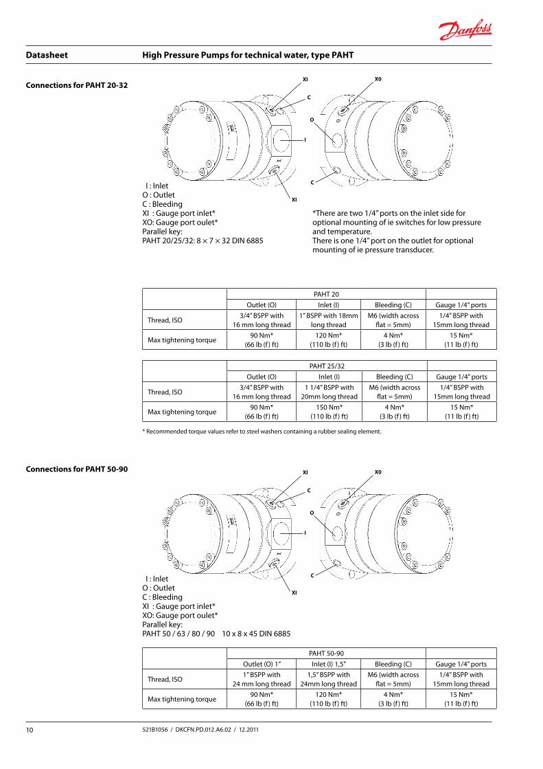
Connections for PAHT 20-32
Connections for PAHT 50-90
I:InletO:OutletC:BleedingXI:Gaugeportinlet*XO:Gaugeportoulet*Parallelkey:PAHT20/25/32:8×7×32DIN6885
I:InletO:OutletC:BleedingXI:Gaugeportinlet*XO:Gaugeportoulet*Parallelkey:PAHT50/63/80/9010x8x45DIN6885
XI
C
I
XI
O
X0
C
*There are two 1/4” ports on the inlet side for optional mounting of ie switches for low pressure and temperature. There is one 1/4” port on the outlet for optional mounting of ie pressure transducer.
PAHT 20Outlet (O) Inlet(I) Bleeding (C) Gauge 1/4” ports
Thread,ISO3/4”BSPPwith
16 mm long thread1”BSPPwith18mm
long threadM6 (width across
flat = 5mm)1/4”BSPPwith
15mm long thread
Max tightening torque90 Nm*
(66 lb (f ) ft)120 Nm*
(110 lb (f ) ft)4 Nm*
(3lb(f )ft)15 Nm*
(11 lb (f ) ft)
PAHT25/32Outlet (O) Inlet(I) Bleeding (C) Gauge 1/4” ports
Thread,ISO3/4”BSPPwith
16 mm long thread11/4”BSPPwith
20mm long threadM6 (width across
flat = 5mm)1/4”BSPPwith
15mm long thread
Max tightening torque90 Nm*
(66 lb (f ) ft)150 Nm*
(110 lb (f ) ft)4 Nm*
(3lb(f )ft)15 Nm*
(11 lb (f ) ft)
*Recommendedtorquevaluesrefertosteelwasherscontainingarubbersealingelement.
XI
C
I
XI
O
X0
C
PAHT 50-90Outlet (O) 1” Inlet(I)1,5” Bleeding (C) Gauge 1/4” ports
Thread,ISO1”BSPPwith
24 mm long thread1,5”BSPPwith
24mm long threadM6 (width across
flat = 5mm)1/4”BSPPwith
15mm long thread
Max tightening torque90 Nm*
(66 lb (f ) ft)120 Nm*
(110 lb (f ) ft)4 Nm*
(3lb(f )ft)15 Nm*
(11 lb (f ) ft)

Datasheet High Pressure Pumps for technical water, type PAHT
11 521B1056 / DKCFN.PD.012.A6.02 / 12.2011
Connections for PAHT 256
I:InletO:OutletC:Bleeding
Parallelkey:PAHT25612x8x70DIN6885
PAHT 256Outlet (O) 2” Inlet(I)2” Bleeding (C)
Thread,ISO2”BSPPwith
24 mm long thread2”BSPPwith
24mm long threadM6 (width across
flat = 5mm)
Max tightening torque90 Nm*
(66 lb (f ) ft)120 Nm*
(110 lb (f ) ft)4 Nm*
(3lb(f )ft)
O
I
C

Datasheet High Pressure Pumps for technical water, type PAHT
12521B1056 / DKCFN.PD.012.A6.02 / 12.2011
Dimensions for PAHT 20-32

Datasheet High Pressure Pumps for technical water, type PAHT
13 521B1056 / DKCFN.PD.012.A6.02 / 12.2011
Dimensions PAHT 50-90

Datasheet High Pressure Pumps for technical water, type PAHT
14 521B1056 / DKCFN.PD.012.A6.02 / 12.2011
Dimensions PAHT 256