High-precision method for measuring the photothermal properties...
4
COL 9(12), 120001(2011) CHINESE OPTICS LETTERS December 10, 2011 High-precision method for measuring the photothermal properties of transparent media with digital holography (Invited Paper) David C. Clark and Myung K. Kim * Digital Holography and Microscopy Laboratory, Department of Physics, University of South Florida, 4202 E. Fowler Avenue, Tampa, Florida 33620, USA * Corresponding author: [email protected] Received August 26, 2011; accepted September 15, 2011; posted online November 18, 2011 Quantitative phase microscopy by digital holography provides direct access to the phase profile of a trans- parent subject with high precision. This is useful for observing phenomena that modulate phase, but are otherwise difficult or impossible to detect. In this letter, a carefully constructed digital holographic apparatus is used to measure optically induced thermal lensing with an optical path difference precision of less than 1 nm. Furthermore, by taking advantage of the radial symmetry of a thermal lens, such data are processed to determine the absorption coefficient of transparent media with precisions as low as 1×10 -5 cm -1 using low power (30 mW) continuous wave (CW) excitation. OCIS codes: 090.0090, 090.1995, 350.6830. doi: 10.3788/COL201109.120001. When a beam of incident light passes through a medium, that medium may absorb some energy of the beam. This absorbed energy causes a change in temperature of the absorbing region of the media, which diffuses to other parts of the medium in a way described by its thermal properties. Since the index of refraction is a temperature dependant property, the temperature gradient results in a refractive index gradient and, therefore, an optical path difference. This effect is referred to as thermal lensing and has been the focus of many other studies as an indica- tor of the optical and thermal properties of materials [1-3] . Due to the change in optical path length, a resulting phase shift can be detected at a plane on the far side of the medium. The description of this result can be sim- plified if the dimensions of the sample are such that the edge effects and container medium can be ignored rela- tive to the effects in the sample medium itself. Such a model has previously been developed, and is known as the two-dimensional (2D) infinite model [4] . This model mathematically relates the resulting phase shift to the photothermal properties of the medium in a focused con- tinuous wave (CW) excitation laser beam and an unfo- cused or collimated imaging beam, such as that used in this letter. The validity of the 2D infinite model is based on sev- eral assumptions, and the experimental design should take these into account. The sample cell path length should be comparable to the confocal parameter (twice the Rayleigh range) of the excitation beam to ensure that the spot size remains relatively constant through the sample. In addition, the sample cell dimensions should be large compared with the excitation beam radius so that both radial and axial edge effects can be ignored. The sample should absorb very little power to avoid convec- tion effects. Finally, the temperature coefficient of the refractive index, dn dT , should be constant in the range of temperatures observed. With these assumptions in mind, the laser-induced change in temperature within the sam- ple can be described. Using expressions for the heat gen- erated in a sample by a Gaussian excitation beam and the corresponding solution to the heat transfer equation, a previous study [4] has derived the following relation: ΔT (r, t)= 2Pα πcρw 2 t Z 0 1 1+2t 0 /τ exp - 2r 2 /w 2 1+2t 0 /τ ¶ dt 0 , (1) where r is the radial distance from the beam axis; t is the time of exposure to the excitation beam; P is the total excitation beam power at the sample; α, c, and ρ are the absorption coefficient, specific heat and density of the sample, respectively; w is the excitation beam radius in the sample. The characteristic thermal time constant, τ , is given by τ = w 2 cρ 4κ with thermal conductivity, κ. The resulting refractive index gradient can be described by n(r, t)= n 0 + dn dT ΔT (r, t), (2) where n 0 is the index of refraction at the starting tem- perature of the sample. This leads directly to phase shift described by φ = 2π λ l [n(r, t) - n(0,t)] = 2π λ l dn dT [ΔT (r, t) - ΔT (0,t)] , (3) where λ is the wavelength of the probe beam, and l is the thickness of the sample. Substituting Eq. (1) into Eq. (3), the phase shift can be rewritten as φ = θ t Z 0 1 1+2t 0 /τ • 1 - exp - 2r 2 /w 2 1+2t 0 /τ ¶‚ dt 0 τ , (4) where θ = - P αl(dn/dT ) κλ . (5) 1671-7694/2011/120001(4) 120001-1 c 2011 Chinese Optics Letters
Transcript of High-precision method for measuring the photothermal properties...

COL 9(12), 120001(2011) CHINESE OPTICS LETTERS December 10, 2011
High-precision method for measuring the photothermalproperties of transparent media with digital holography
(Invited Paper)
David C. Clark and Myung K. Kim∗
Digital Holography and Microscopy Laboratory, Department of Physics, University of South Florida, 4202 E. Fowler Avenue,
Tampa, Florida 33620, USA∗Corresponding author: [email protected]
Received August 26, 2011; accepted September 15, 2011; posted online November 18, 2011
Quantitative phase microscopy by digital holography provides direct access to the phase profile of a trans-parent subject with high precision. This is useful for observing phenomena that modulate phase, butare otherwise difficult or impossible to detect. In this letter, a carefully constructed digital holographicapparatus is used to measure optically induced thermal lensing with an optical path difference precision ofless than 1 nm. Furthermore, by taking advantage of the radial symmetry of a thermal lens, such data areprocessed to determine the absorption coefficient of transparent media with precisions as low as 1×10⁻⁵
cm−1 using low power (30 mW) continuous wave (CW) excitation.OCIS codes: 090.0090, 090.1995, 350.6830.doi: 10.3788/COL201109.120001.
When a beam of incident light passes through a medium,that medium may absorb some energy of the beam. Thisabsorbed energy causes a change in temperature of theabsorbing region of the media, which diffuses to otherparts of the medium in a way described by its thermalproperties. Since the index of refraction is a temperaturedependant property, the temperature gradient results ina refractive index gradient and, therefore, an optical pathdifference. This effect is referred to as thermal lensingand has been the focus of many other studies as an indica-tor of the optical and thermal properties of materials[1−3].
Due to the change in optical path length, a resultingphase shift can be detected at a plane on the far side ofthe medium. The description of this result can be sim-plified if the dimensions of the sample are such that theedge effects and container medium can be ignored rela-tive to the effects in the sample medium itself. Such amodel has previously been developed, and is known asthe two-dimensional (2D) infinite model[4]. This modelmathematically relates the resulting phase shift to thephotothermal properties of the medium in a focused con-tinuous wave (CW) excitation laser beam and an unfo-cused or collimated imaging beam, such as that used inthis letter.
The validity of the 2D infinite model is based on sev-eral assumptions, and the experimental design shouldtake these into account. The sample cell path lengthshould be comparable to the confocal parameter (twicethe Rayleigh range) of the excitation beam to ensurethat the spot size remains relatively constant through thesample. In addition, the sample cell dimensions should belarge compared with the excitation beam radius so thatboth radial and axial edge effects can be ignored. Thesample should absorb very little power to avoid convec-tion effects. Finally, the temperature coefficient of therefractive index, dn
dT , should be constant in the range oftemperatures observed. With these assumptions in mind,the laser-induced change in temperature within the sam-ple can be described. Using expressions for the heat gen-
erated in a sample by a Gaussian excitation beam andthe corresponding solution to the heat transfer equation,a previous study[4] has derived the following relation:
∆T (r, t) =2Pα
πcρw2
t∫
0
11 + 2t′/τ
exp(− 2r2/w2
1 + 2t′/τ
)dt′,
(1)
where r is the radial distance from the beam axis; t is thetime of exposure to the excitation beam; P is the totalexcitation beam power at the sample; α, c, and ρ are theabsorption coefficient, specific heat and density of thesample, respectively; w is the excitation beam radius inthe sample. The characteristic thermal time constant, τ ,is given by τ = w2cρ
4κ with thermal conductivity, κ. Theresulting refractive index gradient can be described by
n(r, t) = n0 +dn
dT∆T (r, t), (2)
where n0 is the index of refraction at the starting tem-perature of the sample. This leads directly to phase shiftdescribed by
φ =2π
λl [n(r, t)− n(0, t)]
=2π
λldn
dT[∆T (r, t)−∆T (0, t)] , (3)
where λ is the wavelength of the probe beam, and l is thethickness of the sample. Substituting Eq. (1) into Eq.(3), the phase shift can be rewritten as
φ = θ
t∫
0
11 + 2t′/τ
[1− exp
(− 2r2/w2
1 + 2t′/τ
)]dt′
τ, (4)
where
θ = −Pαl(dn/dT )κλ
. (5)
1671-7694/2011/120001(4) 120001-1 c© 2011 Chinese Optics Letters

COL 9(12), 120001(2011) CHINESE OPTICS LETTERS December 10, 2011
Fig. 1. (Color online) Experimental apparatus. The excita-tion beam (red) is reflected downward by the DM through thesample by the probe-shared objective lens. The probe beam(green) is the object arm of the MZI, which passes upwardthrough the sample, combines with the reference beam, andcreates the hologram captured by the CCD camera.
Previous experimental methods have been developed toapproximate this phase shift and then used to measurevery low absorption coefficients of materials, demon-strating good agreement with expected values througha far-field diffraction technique[1,2]. These methods re-quire additional mathematical approximation and fittingto determine the change in the wavefront of the incidentbeam and, therefore, the phase shift resulting from thethermal lens. Since digital holography is a phase imagingmethod[5,6], this phase shift can be directly measured,without further approximations, following a process sim-ilar to photothermal interferometry[7]. In addition, thereis no necessary minimum distance from the thermal lensto the detector plane when measuring by digital holog-raphy. Our previous work has shown that improvedaccuracy and precision over these traditional methodsis achieved through the use of digital holography[3]. Inthis letter, we describe our use of quantitative phasemicroscopy by digital holography (DH-QPM) in a highprecision method to map the thermal lens and measurethe absorption coefficient of transparent media using lowexcitation power. The goal of this study is to maximizethe use of the data collected by an optimized system toachieve improved measurement precision with standardoptical laboratory components.
Figure 1 shows a diagram of the experimental appa-ratus. We used a Mach-Zehnder interferometer (MZI)to create the hologram of the sample using low power(∼1 mW) 532-nm laser light. In the experiment, theimaging beam arrived collimated at a beam splitter (BS)that then transmitted half the beam into the referencearm and reflected half the beam into the object armof the setup. The beams each followed a similar path(through matching singlet objective lenses) before re-combining through another BS, with the main differencebeing that the object beam had passed through the sam-ple area of the interferometer. The interference of thephase-modulated object beam with the reference beamcreated the hologram, which was recorded by a digital
CCD camera placed atop the setup and passed into ourLabVIEW personal computer platform for amplitudeand phase reconstruction based on the angular spectrummethod[8].
An integrated optical excitation arm delivered a 30-mW, 632.8-nm CW laser beam to the system. After-wards, the beam passed through a 10:1 focal length lenspair to create a much reduced beam radius. A dichroicmirror (DM) reflected this excitation beam down towardthe sample while allowing the probe beam to transmit uptoward the CCD camera. The excitation beam passedthrough the shared objective lens, which in turn, focusedthe already thin beam through the sample area. The ob-jectives were chosen to have long effective focal lengths inorder to meet the requirements of the 2D infinite modeldescribed above. A removable green bandpass filter wasplaced just in front of the CCD camera to filter out any632.8-nm excitation light leaking through the DM. This“leaky” light, however, can be used to profile the excita-tion beam by temporarily removing the green filter. Theexcitation beam radius, w, is defined as the radius atwhich the Gaussian beam intensity is reduced to e−2 ofits maximum. With the green filter in place, a hologramcontaining complete phase and amplitude informationwas captured by the CCD camera and processed by oursoftware routines. This process reconstructed the phaseimage both with and without excitation.
The sample consisted of a pure liquid in a glass cuvette(5 × 10 × 45) with a sealable lid. With the excitationbeam profiled and adjusted to a desired radius using theexcitation arm lenses, the sample was placed on the sam-ple stage on its side oriented with a 5-mm path length.The sample stage can be adjusted in z to optimize thelocation of the sample for the desired beam radius. Atthis time, all general phase aberrations, including wave-front curvature mismatch, can be easily compensatedby storing a background phase image and subtractingthis from subsequent images. While viewing the baselinephase image shown in Fig. 2(a), the optical excitationbeam was turned on and a thermal lens became visible,as demonstrated in Fig. 2(b).
Our previous work has demonstrated excellent tempo-ral and spatial agreement with the 2D infinite model[9].Therefore, in this letter, we used optically triggeredtiming to capture the data at precisely 4 000 ms after ex-citation begins, with a shutter speed of less than 100 µs.
Fig. 2. Example phase maps of a sample with (a) no exci-tation and (b) optical excitation resulting in a thermal lens(higher power excitation was used here to improve structurevisibility for print). Phase shift is represented as dark forsmaller values and light for higher values. Field of view is 100µm.
120001-2

COL 9(12), 120001(2011) CHINESE OPTICS LETTERS December 10, 2011
Table 1. Experimental Parameters for BenzylAlcohol
Parameter Symbol Value
Power (mW) P 30
Excitation Beam Radius (µm) w 70
Probe Beam Wavelength (nm) λ 532
Sample Cell Path Length (mm) l 5.0
Excitation Duration (s) t 4.000
Refractive Index (20◦C)1 n0 1.540
Thermal Conductivity1 (W/(m·◦C)) k 0.159
Specific Heat Capacity1(J/(g·k)) c 2.02
Density1 (g/ml) ρ 1.044
Thermal Time Constant (ms) τ 16.2
Temp. Coefficient of RI2 (◦C−1) dn/dT −3.5×10⁻⁴
Absorption Coefficient (cm−1) αexp (6.4±0.1)×10−4
1CRC Handbook of Chemistry and Physics, 2008.2El-Kashef, Hassan, and El-Ghazaly, App. Opt. 33, 3540(1994).
At this time, the rate of change of thermal lens phasesignal significantly reduced (∼0.001 rad/s); thus, anyerror from our timing mechanism would be negligible.
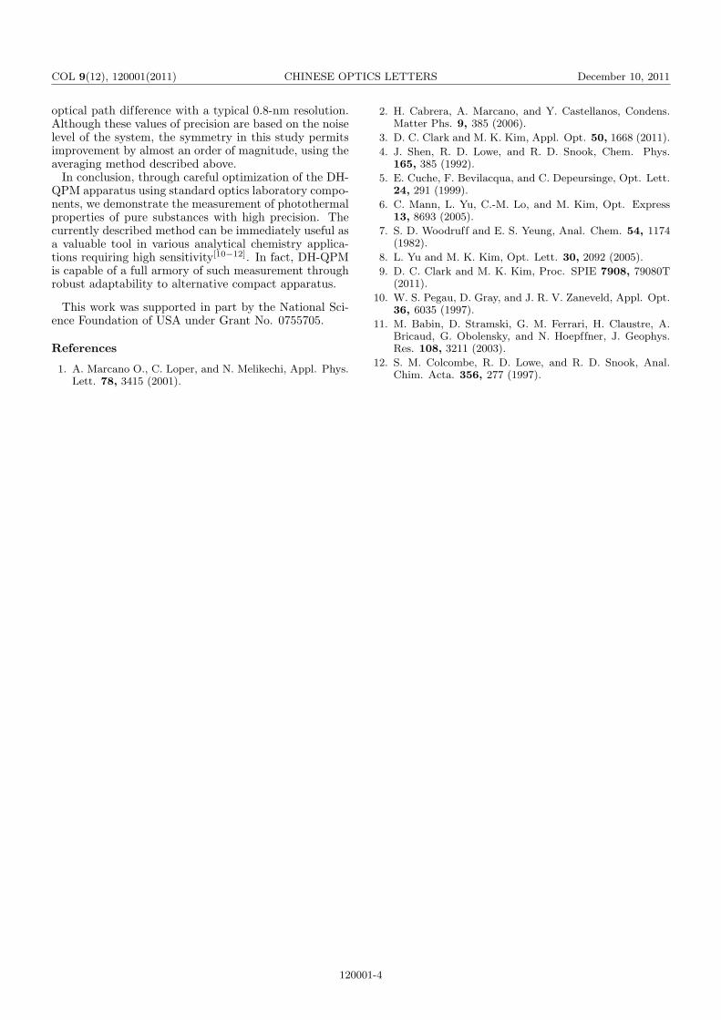
Table 1 indicates the experimental parameters ofbenzyl alcohol, a transparent liquid. The absorptioncoefficient at 632.8 nm, αexp, was determined exper-imentally to be (6.4±0.1) × 10−4 cm−1 as describedherein. By taking a single cross-section through the cen-ter of the thermal lens structure in the phase map, aprofile of the thermal lens phase signal versus positionwas obtained as shown in Fig. 3. While this raw datademonstrates an impressive precision (better than ±0.01rad), it does not adequately represent the large amountof data collected by this method.
In order to maximize the use of the 2D array of data, weconsider the radial symmetry of the structure being mea-sured. The center of the thermal lens was determined bylocating the X- and Y -minima, after which a suitable ra-dius was selected. A simple algorithm averaged the phasedata around the circumference of the circle for each radialdistance to produce a one-dimensional (1D) array of av-eraged phase values versus radial distance. We used 100points around the circumference for averaging. This re-sult is plotted in Fig. 4, along with the model prediction
Fig. 3. Single cross-section through center of the thermal lensphase structure.
Fig. 4. Phase shift versus radial distance from the center ofexcitation beam for experimental data (dotted) and modelpredictions (solid) for a thermal lens in benzyl alcohol. Shiftat the origin is set to zero as a reference to the rest of thethermal lens.
using the experimentally determined absorptioncoefficient. Although the deviation is very small, wenote here that there is greater deviation toward the cen-ter of the structure where the model assumes a constantexcitation beam radius through the sample. Certainly,this is not actually true for a focused excitation beam andthis small difference is detectable by the current method.The data taken at a sufficient distance from this artifact(in this case, 170 µm or further from the origin) neverdeviates more than 0.002 rad from the model prediction.
We display the entire radial path here to demonstratethe strength of the relationship between the experimentand the model; however, determining the absorptioncoefficient only requires the selection of a single radiallocation. The most suitable selection is typically thefarthest distance from the center of the thermal lensstructure that still allows complete circular averaging.However, as demonstrated, many selections are availablewith little or no consequence. Additionally, if the rawdata are particularly noisy, the number of points aroundthe circle for averaging can be increased (within theconfines of the data array size).
The noise levels of our system were mathematically de-termined between each measurement by phase imagingthe sample, with no excitation beam present and by tak-ing the standard deviation of the raw single cross-sectionto indicate background noise. Values ranged between0.003 and 0.015 rad, with 0.01 rad as the average. Inaddition to the determination of absorption coefficient,the phase shift caused by a thermal lens has a directmathematical relationship with shifts in temperature,index of refraction, and optical path length of the mediaas described by Eq. (3). As such, a direct measurementof the phase shift yields these parameters with similarrelative precision. By substituting the current typicalnoise level of our system (0.01 rad) into Eq. (3) andsolving for the temperature shift difference, the abso-lute difference in temperature between any two pointscan be determined to a precision of 0.0005 K. Similarly,the shift in refractive index is determined with 1.7 ×10⁻⁷ precision. Optical path difference is described byl (∆n), where l is our cuvette path length (5 mm), and∆n is the refractive index difference. Therefore, at thecurrent typical noise level, this system determines the
120001-3
COL 9(12), 120001(2011) CHINESE OPTICS LETTERS December 10, 2011
optical path difference with a typical 0.8-nm resolution.Although these values of precision are based on the noiselevel of the system, the symmetry in this study permitsimprovement by almost an order of magnitude, using theaveraging method described above.
In conclusion, through careful optimization of the DH-QPM apparatus using standard optics laboratory compo-nents, we demonstrate the measurement of photothermalproperties of pure substances with high precision. Thecurrently described method can be immediately useful asa valuable tool in various analytical chemistry applica-tions requiring high sensitivity[10−12]. In fact, DH-QPMis capable of a full armory of such measurement throughrobust adaptability to alternative compact apparatus.
This work was supported in part by the National Sci-ence Foundation of USA under Grant No. 0755705.
References
1. A. Marcano O., C. Loper, and N. Melikechi, Appl. Phys.Lett. 78, 3415 (2001).
2. H. Cabrera, A. Marcano, and Y. Castellanos, Condens.Matter Phs. 9, 385 (2006).
3. D. C. Clark and M. K. Kim, Appl. Opt. 50, 1668 (2011).
4. J. Shen, R. D. Lowe, and R. D. Snook, Chem. Phys.165, 385 (1992).
5. E. Cuche, F. Bevilacqua, and C. Depeursinge, Opt. Lett.24, 291 (1999).
6. C. Mann, L. Yu, C.-M. Lo, and M. Kim, Opt. Express13, 8693 (2005).
7. S. D. Woodruff and E. S. Yeung, Anal. Chem. 54, 1174(1982).
8. L. Yu and M. K. Kim, Opt. Lett. 30, 2092 (2005).
9. D. C. Clark and M. K. Kim, Proc. SPIE 7908, 79080T(2011).
10. W. S. Pegau, D. Gray, and J. R. V. Zaneveld, Appl. Opt.36, 6035 (1997).
11. M. Babin, D. Stramski, G. M. Ferrari, H. Claustre, A.Bricaud, G. Obolensky, and N. Hoepffner, J. Geophys.Res. 108, 3211 (2003).
12. S. M. Colcombe, R. D. Lowe, and R. D. Snook, Anal.Chim. Acta. 356, 277 (1997).
120001-4
![Holographic 3D Photography Under Ambient Lightfaculty.cas.usf.edu/mkkim/conference_papers/2014 ICTC.pdf · macroscopic objects and 3D fluorescence microscopy [10, 11]. This report](https://static.fdocuments.us/doc/165x107/605af1054eaf5d7ac01e2957/holographic-3d-photography-under-ambient-ictcpdf-macroscopic-objects-and-3d-fluorescence.jpg)


