Project Reference TIGER KW Tierfehd 380kV / 220kV / 50kV / 16kV ...

High power DC/DC Converter
Catalogue of circuits
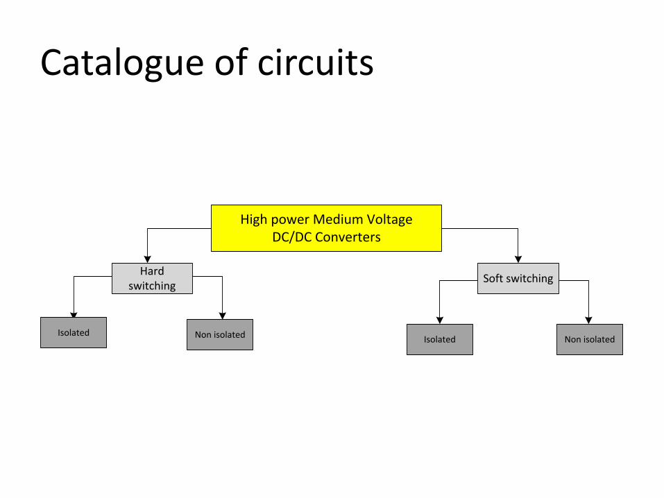
High power Medium Voltage DC/DC Converters
Soft switchingHard switching
Isolated Non isolated Isolated Non isolated
Catalogue of circuits
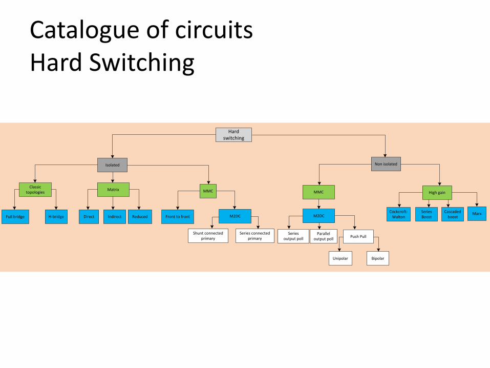
Catalogue of circuits Hard Switching
Isolated Non isolated
Cascaded boostFull bridge H-bridge
Matrix MMC MMC
Front to front M2DC
Shunt connected primary
Series connected primary
M2DC
Series output poll
Parallel output poll Push Pull
Unipolar Bipolar
High gainClassic
topologies
Direct Indirect ReducedMarx
Hard switching
Cockcroft-Walton
Series Boost

Catalogue of circuits Soft Switching
Quasi-Resonant Converters Multiresonant ConvertersConventional Resonant
Converters
Phase Shift-Modulated Load-Resonant Converters
Series ResonantConverters
Parallel Resonant Converters
Series-Parallel Resonant Converters
Constant Frequency Operation
Variable Frequency Operation
Constant Frequency Operation
Variable Frequency Operation
Soft switching
Non isolated
High gain
Step up DC/DC
Switched Capacitor Cell
Isolated
Phase shiftResonantMMC
Single Active Bridge
Dual Active Bridge
Quasi two level (Q2L) ARCP
Resonant
Voltage Multiplier
Converters with resonant switches
Resonant Transition Converters

Hard switching-Isolated 1. Half Bridge
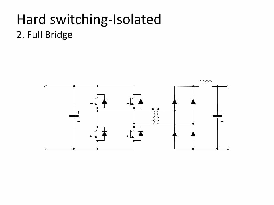
Hard switching-Isolated 2. Full Bridge
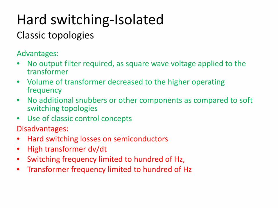
Hard switching-Isolated Classic topologies
Advantages: • No output filter required, as square wave voltage applied to the
transformer • Volume of transformer decreased to the higher operating
frequency • No additional snubbers or other components as compared to soft
switching topologies • Use of classic control concepts Disadvantages: • Hard switching losses on semiconductors • High transformer dv/dt • Switching frequency limited to hundred of Hz, • Transformer frequency limited to hundred of Hz

Hard switching-Isolated 3. Direct Matrix
LC filter
Direct Matrix

Hard switching-Isolated 4. Indirect Matrix
Indirect Matrix

Hard switching-Isolated 5. Reduced Matrix
Reduced Matrix

Hard switching-Isolated Matrix converter
Advantages: • 3 power stages • Fewer switches, less switching and ON-state losses • Smaller transformer due to higher frequency • The best trade off between efficiency, power density and power to mass ration when the
AC-AC converter topology is the direct matrix converter, the AC link frequency is selected around 1 kHz and the power per module is in the range of 2.5 to 4MW
• Compared to conventional 3AC-AC converter with DC Link, it was found that for range of transformer frequencies from 1khz to 20khz, the RMC topology has the most efficieny topology and the higherst power density
• No DC Link capacitors, saving space and components • Higher efficiency than B2B topology, due to fewer converter stages Disadvantages: • All matrix topologies require a clamp circuit as they do not have natural freewheeling path • The RMC needs to be protected against the overvoltages that might be destructive for
semiconductors
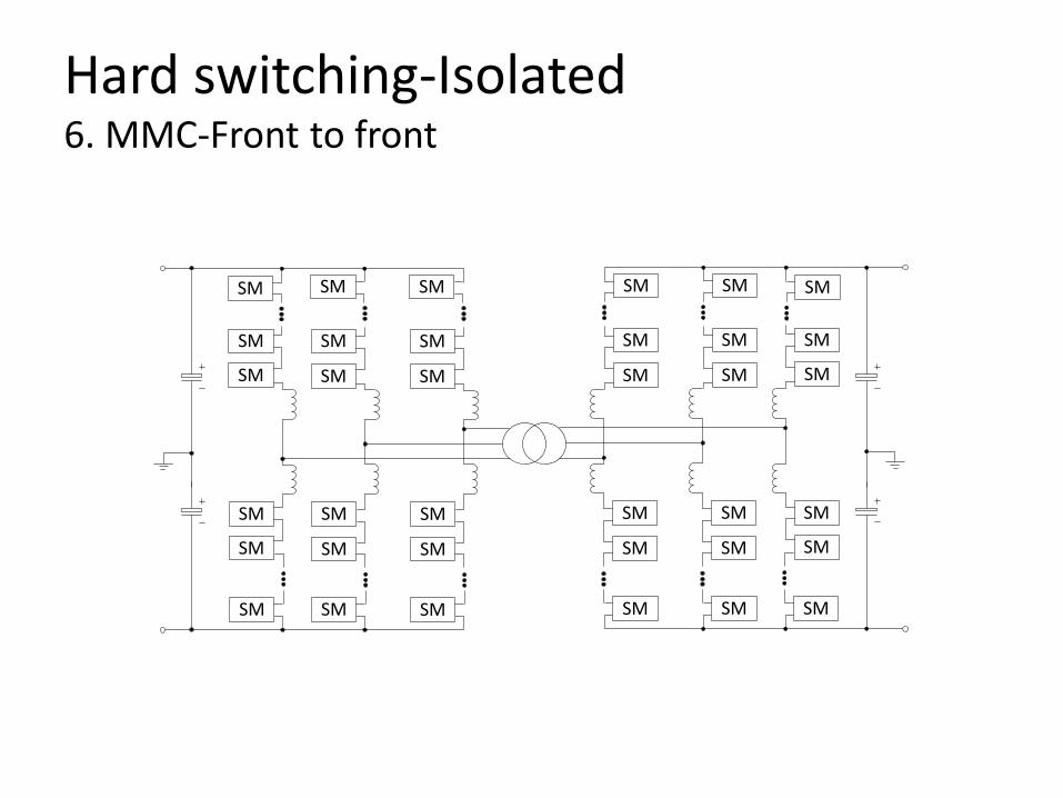
Hard switching-Isolated 6. MMC-Front to front
SM SM
SM SM
SM SM
SM SM
SM SM
SM SM
SM
SM
SM
SM
SM
SM
SMSM
SMSM
SMSM
SMSM
SMSM
SMSM
SM
SM
SM
SM
SM
SM

Hard switching-Isolated 6. MMC-Front to front Advantages: • - low switching losses • - Voltage across each module can be controlled separately • - Easier voltage balancing across the switches • - High voltage applications motivate the use of modular converter systems • - Potential replacement for the cascaded multilevel converter in medium voltage applications • - Fault tolerant operation • - operation independent of ac side power factors and modulation indices • - extendibility without capacitor voltage balancing problems. • - Transformer winding can experience low dv/dt • - The MMC can be controlled in a similar manner like the DAB, using phase shift switching actions • - Able to interrupt power flow without using a circuit breaker • - High efficiency for high powers >99.5% Disadvangages: • - Capacitors occupy a large fraction of the volume • - Increase in power circuit and control complexity
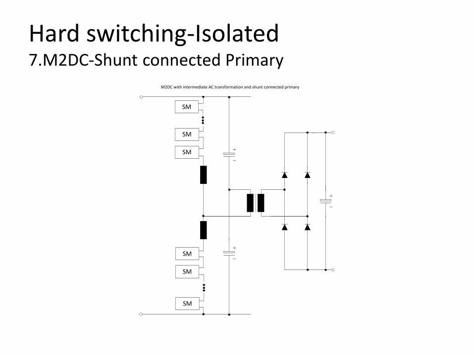
Hard switching-Isolated 7.M2DC-Shunt connected Primary
SM
SM
SM
SM
SM
SM
M2DC with intermediate AC transformation and shunt connected primary

Hard switching-Isolated 8. M2DC Series Connected Primary
SM
SM
SM
SM
SM
SM
Hard Switching-Isolated M2DC Advantages: • Do not suffer from energy drift • Full fault propagation prevention due to galvanic separation • Main application for HVDC taps (500kV to 50kV) • Lower power capacity factor than the direct conversion • AC frequency can be optimized to achieve the most suitable trade
off between transformer size and switching losses Disadvantages: • The transformer is a significant component in terms of volume and
power losses • Control complexity
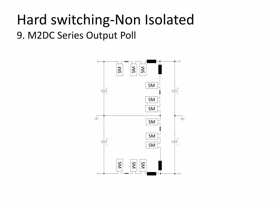
Hard switching-Non Isolated 9. M2DC Series Output Poll
SM SMSM
SM
SM
SM
SM SMSM
SM
SM
SM
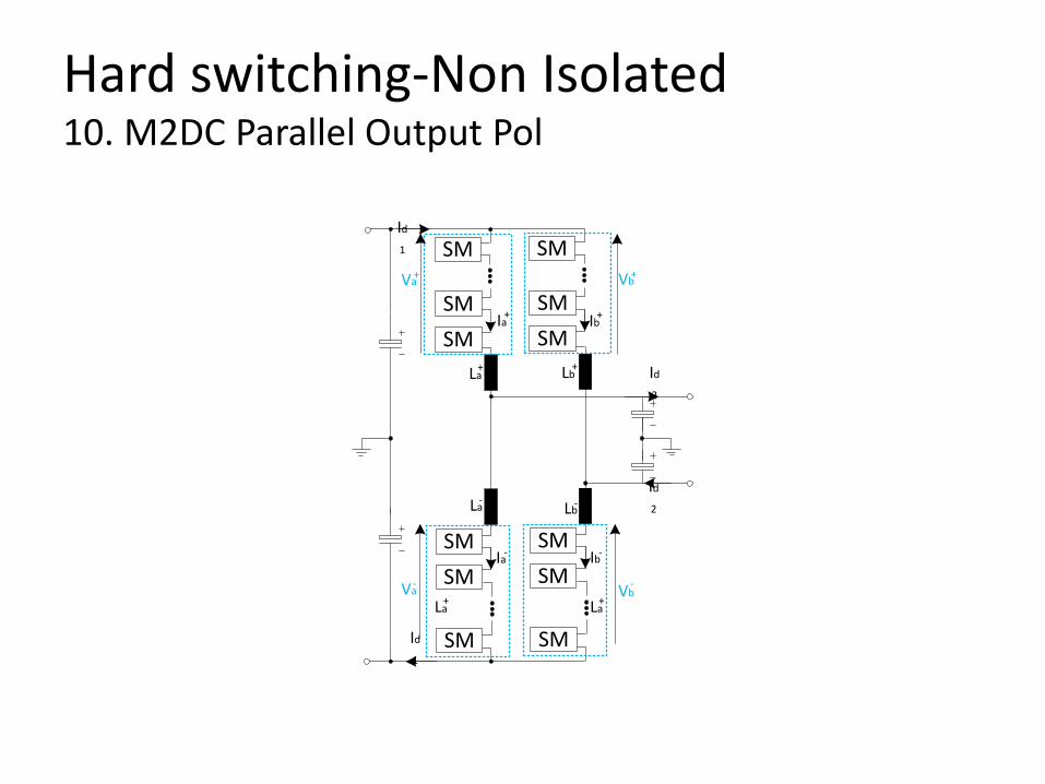
Hard switching-Non Isolated 10. M2DC Parallel Output Pol
SMSM
SMSM
SM
SM
SMSM
SMSM
SM
SM
La+
Lb-
Lb+
La-
Ia+ Ib
+
Ib-Ia-
Id
1
Id
1
Id
2
Id
2
Vb+
La+ La
+
Va+
Va- Vb
-

Hard switching-Non Isolated M2DC Advantages: • - Suitable for direct connection • - Suitable for connecting HVDC links of similar power but different nominal voltages • - DC version of the MMC Disadvantages: • - Control complexity • - Major issues in cell balancing currents • - The non isolated versions suffer from an energy drift and require an internal AC rebalancing
current to be circulated • - Poor power capacity factor which gets worse as the ratio between the DC voltages increases • - They are not suited for interfacing smal amounts of power to a large HVDC • - No galvanic separation • - Suitable for smal voltage gain <2 • - Requires large number of semiconductors, 50% more devices than a conventional buck-boost
converter • - Compared to DAB, the investment cost is at least by a factor of three higher. • which results in a poor efficiency of less than 95.5%
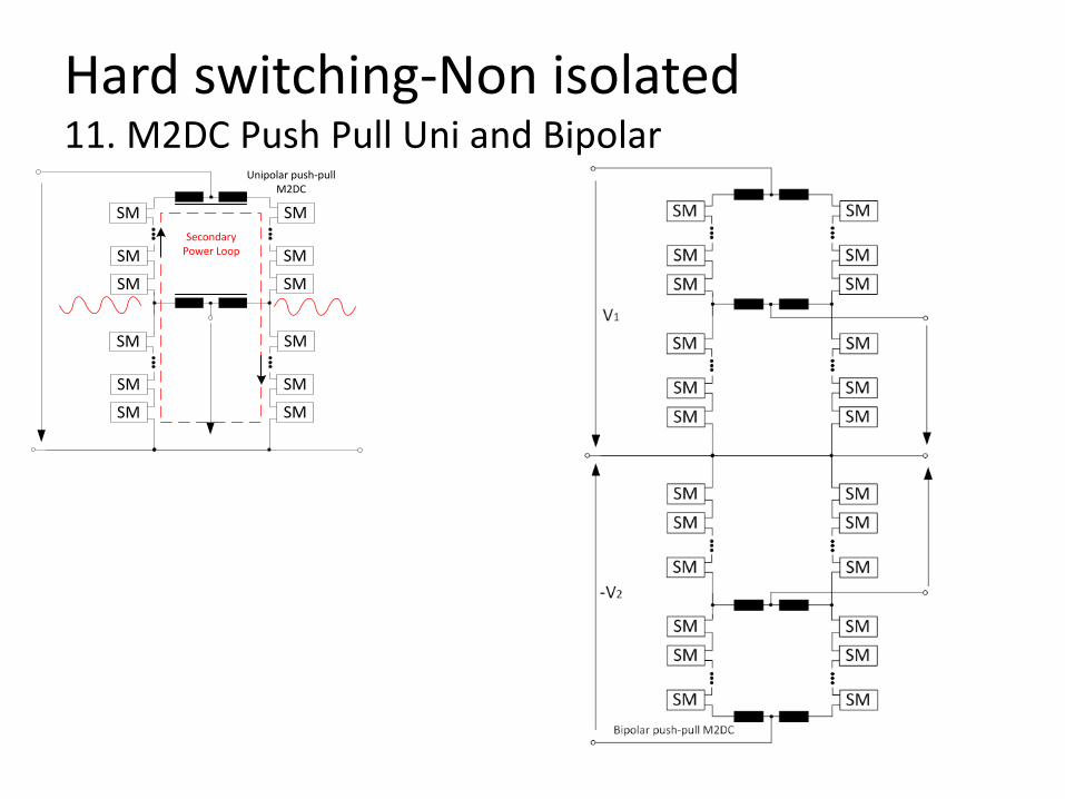
Hard switching-Non isolated 11. M2DC Push Pull Uni and Bipolar
SMSM
SM
SMSM
SM
SMSM
SM
SMSM
SM
Unipolar push-pull M2DC
Secondary Power Loop

Hard switching-Non isolated 11. M2DC Push Pull Uni and Bipolar
Advantages: • Secondary power loop introduced that exchanges
power with the primary power loops at the input and the output
• Power is exchanged between the primary and the secondary loops by using the principle of orthogonality of power flow at different frequencies
Disadvantages: • Control complexity • Not suitable for high voltage ratios, because in this case
the circulating current in the converter becomes high
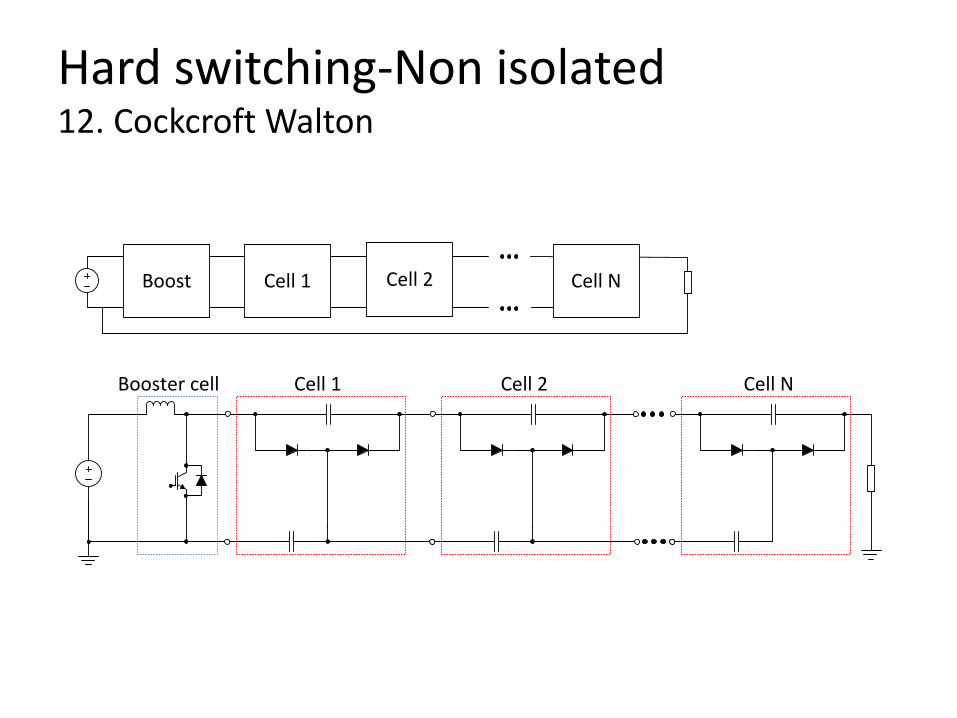
Hard switching-Non isolated 12. Cockcroft Walton
Booster cell Cell 1 Cell 2 Cell N
Cell 1Boost Cell NCell 2

Hard switching-Non isolated 12. Cockcroft Walton Advantages: • - Possible to reach high voltage gain • - Low weight and volume • - Simple control • - Simple structure • - Switches can be diodes • - Soft switching capability • - Ripple cancellation with symmetrical and double ladder Disadvantages: • - Suitable for high voltage, low current applications • - No ripple cancellation with classic ladder • - Poor voltage regulation • - No galvanic separation • - Large ESR capacitors (or series resistances) are prefferable for low current ripple, hence high • output impedance and additional losses • - Pulsed output current • - Insulation to ground • - Voltage sag at higher stages
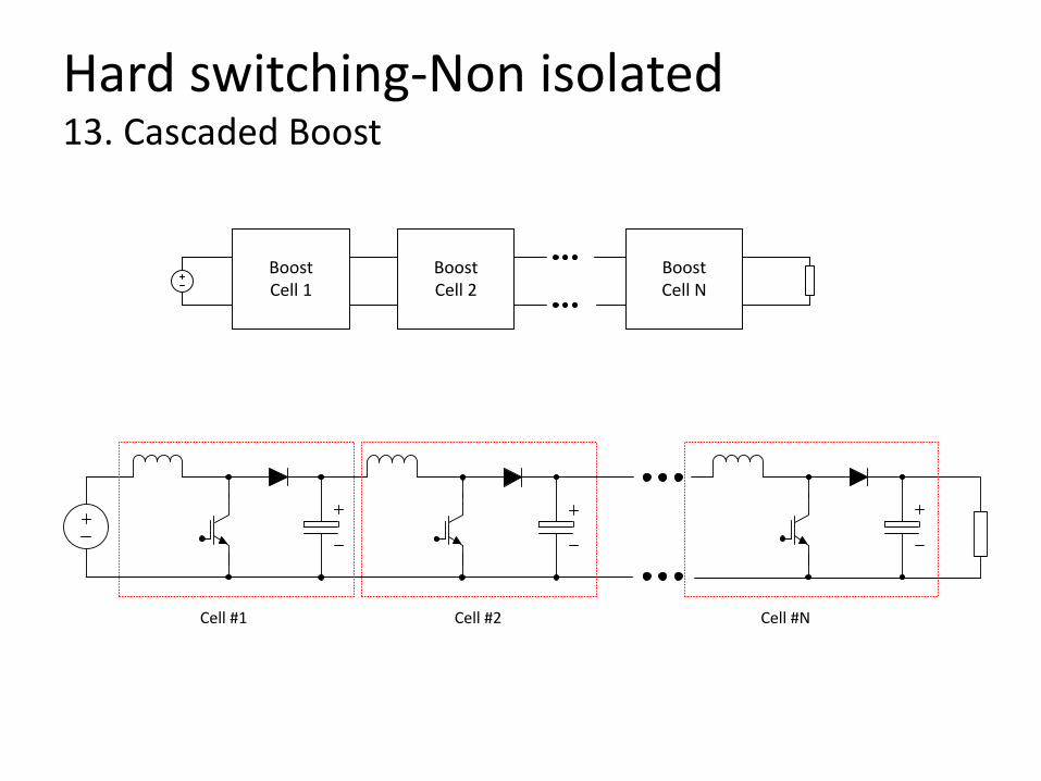
Hard switching-Non isolated 13. Cascaded Boost
Cell #1 Cell #2 Cell #N
BoostCell 2
BoostCell 1
BoostCell N
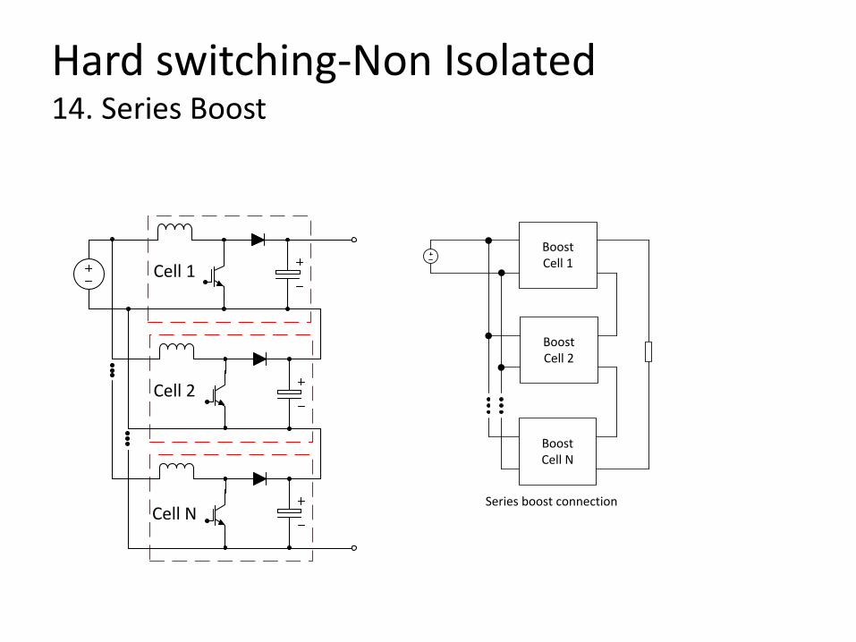
Hard switching-Non Isolated 14. Series Boost
Cell 1
Cell 2
Cell N
BoostCell 1
BoostCell 2
BoostCell N
Series boost connection

Hard switching-Non Isolated Cascaded and Series Boost Advantages: • - Reduced switch and diode voltage stress on lower stages • - High flexibility • - Suitable for high power applications through interleaving connections • - Interleaved operation for low current ripple • - softswitching operation possible through the use of a resonant inductor L
Disadvantages: • - Total power processed N times (according to N stages) • - High switch and diode voltage stress on higher stages • - Maximum and minimum duty-cycle limitation to guarantee soft commutation • - High switch RMS current • - Voltage stress reduction related to the number of cells • - Regarding multiple module boost converter, because the duty ratio of the main switch is large to
achieve high-voltage gain, the switching frequency is relatively low to reduce the losses and also allows sufficient turn-off time for the switches. Therefore, increasing the size of passive elements, such as boost inductors and filter capacitors is inevitable due to low switching frequency.
• - Diode reverse recovery causes loss, even at low frequency and increases the turn-on stress of the power switch.
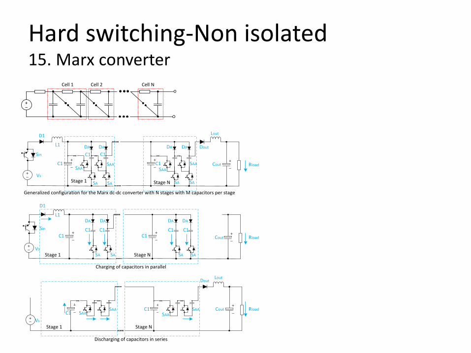
Hard switching-Non isolated 15. Marx converter
Generalized configuration for the Marx dc-dc converter with N stages with M capacitors per stage
Stage 1 Stage N
Cell 1 Cell 2 Cell N
Charging of capacitors in parallel
Stage 1 Stage N
Stage 1 Stage N
Discharging of capacitors in series
Vs
Sin
D1
L1
C1
C1 C1
C1 Cout
Lout
DoutDA DA DA DA
SA SA SA SA
SAASAA
SAASAA
Vs
Sin
D1
L1
C1
DA DA DA DA
Cout Rload
Rload
C1 C1C1C1
SA SA SA SA
C1
Vs
C1C1
SAASAA
SAASAA Rload Cout
LoutDout
Hard switching-Non isolated 15. Marx converter
Advantages: • Compared to boost converter, the Marx dc-dc converter is shown to
be competitive and even advantageous for higher dc gain. At dc gain of 8, the Marx dc-dc converter has lower VA ratings on the inductor, capacitor and IGBT. Efficiency is increasing as the gain increases. At dc gain of 8, the efficiency of the Marx converter is evaluated at 98.3% compared to 96.8% for the boost converter (insert reference).
• Possibility of soft switching Disadvantages: • - Doesn’t have voltage regulator property. It only amplifies its input
voltage by the designed gain. As a result, it is neccesary to add an additional stage at the input that will provide the control variable to regulate the output voltage.

Soft switching-Non Isolated 16. Resonant Cockcroft Walton
DC S
yste
m 1
Cell 1
Cell 1
Cell 1
DC System 1
DC System 2

Soft switching-Isolated 17. Phase shift-Single Active Bridge

Soft switching-Isolated 17. Phase shift-Single Active Bridge
Advantages: - The converter is easy to control and current control can be used - Constant frequency operation - Can be used in high power applications and dc-dc converters - Compact and low-weight design - Can be used in high voltage applications - The leakage inductance can be integrated in the circuit - Low number of passives Disadvantages: - output diodes are hard switched - Interactions of the leakage inductance with the output rectifier - The use of a half bridge as an input bridge is not possible

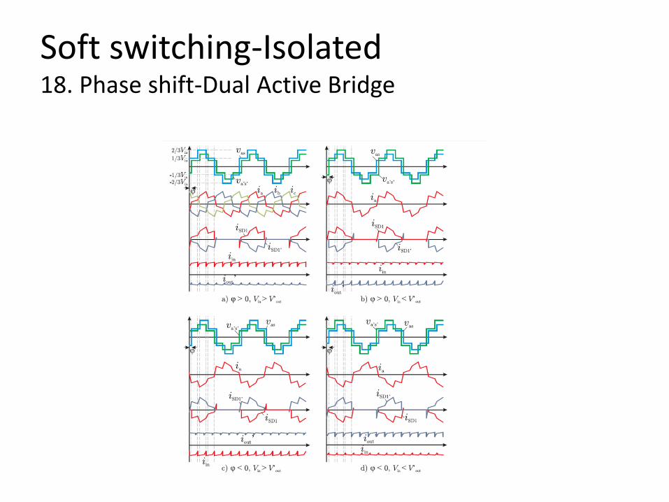
Soft switching-Isolated 18. Phase shift-Dual Active Bridge
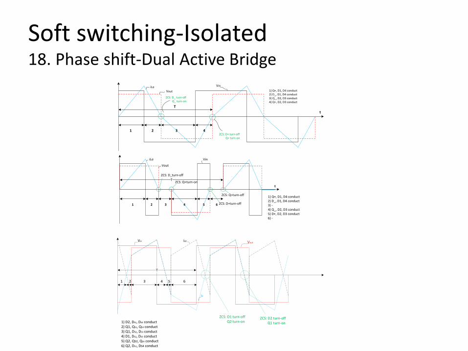
Soft switching-Isolated 18. Phase shift-Dual Active Bridge
T
1 2 3 4
iLσ Vout
Vin
ZCS: D_ turn-off Q_ turn-on
ZCS: D+ turn-off Q+ turn-on
t
1) Q+, D1, D4 conduct2) D_, D1, D4 conduct3) Q_, D2, D3 conduct4) Q+, D2, D3 conduct
t
1) Q+, D1, D4 conduct2) D_, D1, D4 conduct3) - 4) Q_, D2, D3 conduct5) D+, D2, D3 conduct6) -
T
1 2 3 4 5 6
iLσ
Vout
Vin
ZCS: D_turn-off
ZCS: Q+turn-on
ZCS: Q+turn-off
ZCS: D+turn-off
1 2 3 4 5 6
T
iL0
iσ
Vin Vout
ZCS: D1 turn-off Q2 turn-on
ZCS: D2 turn-off Q1 turn-on1) D2, DS1, DS4 conduct
2) Q1, QS1, QS4 conduct3) Q1, DS2, DS3 conduct4) D1, DS2, DS3 conduct5) Q2, QS2, QS3 conduct6) Q2, DS1, DS4 conduct
Soft switching-Isolated 18. Phase shift-Dual Active Bridge

Soft switching-Isolated 18. Phase shift-Dual Active Bridge
Advantages: - Step up and step down operation - Control simplicity - Constant frequency - Minimum number of passive components - Ideally no switching losses without increased conduction losses - By controlling the secondary active switching devices, soft-switching can be achieved Disadvantages: - High ripple current through the output capacitor - Comparably high KVA rating of the transformer - At light loads additional energy is needed in order to achieve ZVS.

Soft switching-Isolated 19. Phase shift-DAB with ARCP
Three phase dual active bridge with ARCP
Soft switching-Isolated 19. Phase shift-DAB with ARCP Advantages: - Has the lowest (as HS-PWM topology) transformer KVA rating - Due to soft switching it can run at higher frequencies and as a result has the smallest transformer compared with other soft-switched topologies - Lower main device stresses than any other soft-switched topology - Current mode and voltage mode PWM control can be used - Simple control Disadvantages: - Large number of passive components - Large number of active components - Output diodes are hard switched - Hald bridge operation is not possible.

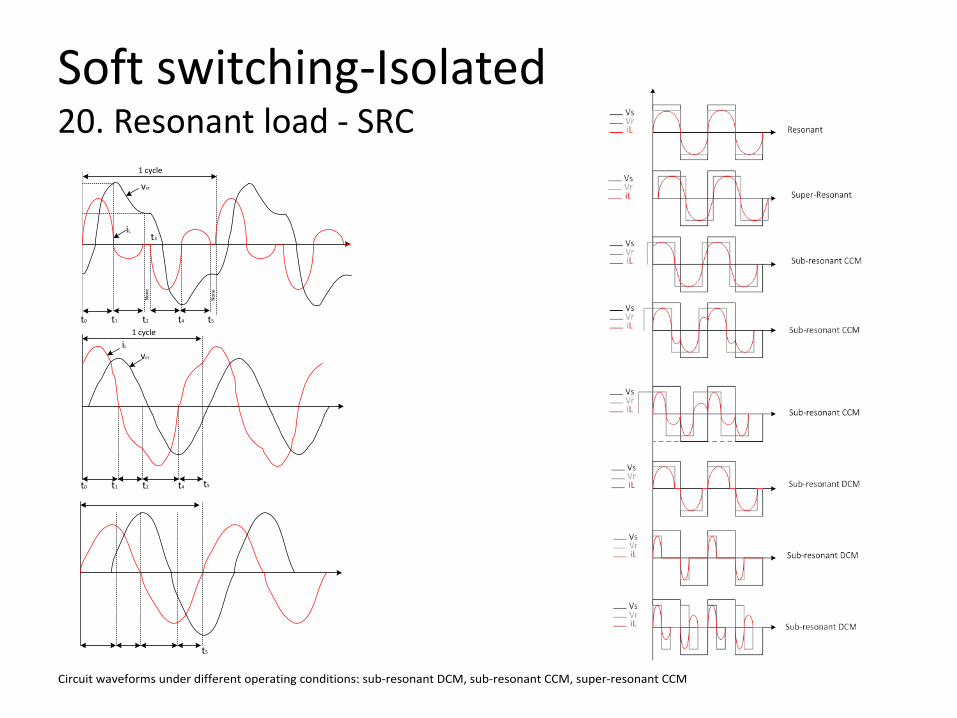
Soft switching-Isolated 20. Resonant load - SRC
CrLr
Lr
Lr
Cr
Cr
L Cs

Soft switching-Isolated 20. Resonant load - SRC
L Cs
Vg
VL VC
VT
CF
+
-
+ -+ -+ -
+
-
VR RLoadVVs
Vs= +Vg
VR= +V
VT= +Vg-V
VT(t)= Vs(t)- VR(t)
iL>0
LCs
Q1Q3
Q4 Q2
D1D3
D2D4
D5
D6 D8
D7
Vg
1) Q1, Q4, D5, D8 conduct (iL >0) => Vc
iL>0
VT= +Vg-V

Soft switching-Isolated 20. Resonant load - SRC
L CsQ1Q3
Q4 Q2
D1D3
D2D4
D5
D6 D8
D7
2) D1, D4, D7, D6 conduct (iL <0) => Vc
VT= +Vg+V
iL<0
L Cs
Vg
VL VC
VT
CF
+
-
+ -+ -+ -
+
-
VR RLoadVVs
Vs= +Vg
VR= -V
VT= +Vg+V
VT(t)= Vs(t)- VR(t)
iL<0
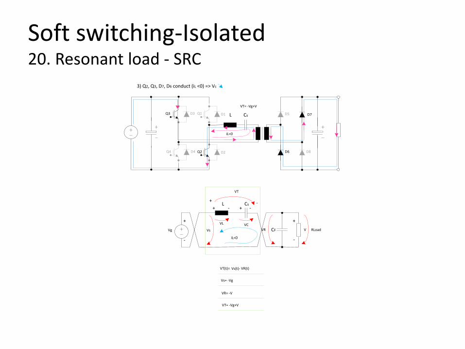
Soft switching-Isolated 20. Resonant load - SRC
L CsQ1Q3
Q4 Q2
D1D3
D2D4
D5
D6 D8
D7
3) Q2, Q3, D7, D6 conduct (iL <0) => Vc
iL<0
VT= -Vg+V
L Cs
Vg
VL VC
VT
CF
+
-
+ -+ -+ -
+
-
VR RLoadVVs
Vs= -Vg
VR= -V
VT= -Vg+V
VT(t)= Vs(t)- VR(t)
iL<0
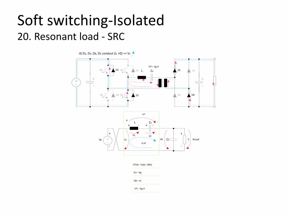
Soft switching-Isolated 20. Resonant load - SRC
4) D2, D3, D8, D5 conduct (iL >0) => Vc
L CsQ1Q3
Q4 Q2
D1D3
D2D4
D5
D6 D8
D7VT= -Vg-V
L Cs
Vg
VL VC
VT
CF
+
-
+ -+ -+ -
+
-
VR RLoadVVs
Vs= -Vg
VR= +V
VT= -Vg-V
VT(t)= Vs(t)- VR(t)
iL>0
Soft switching-Isolated 20. Resonant load - SRC
t0 t1
t3
t4 t5t2
Non
e
Non
e
iL
vcr
1 cycle
t0 t1 t4 t5t2
1 cycleiL
vcr
t5
Circuit waveforms under different operating conditions: sub-resonant DCM, sub-resonant CCM, super-resonant CCM

Soft switching-Isolated 21. Resonant load-SRC
Alternate implementation of SRC
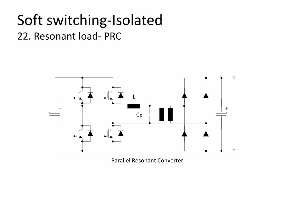
Soft switching-Isolated 22. Resonant load- PRC
Parallel Resonant Converter
L
Cp
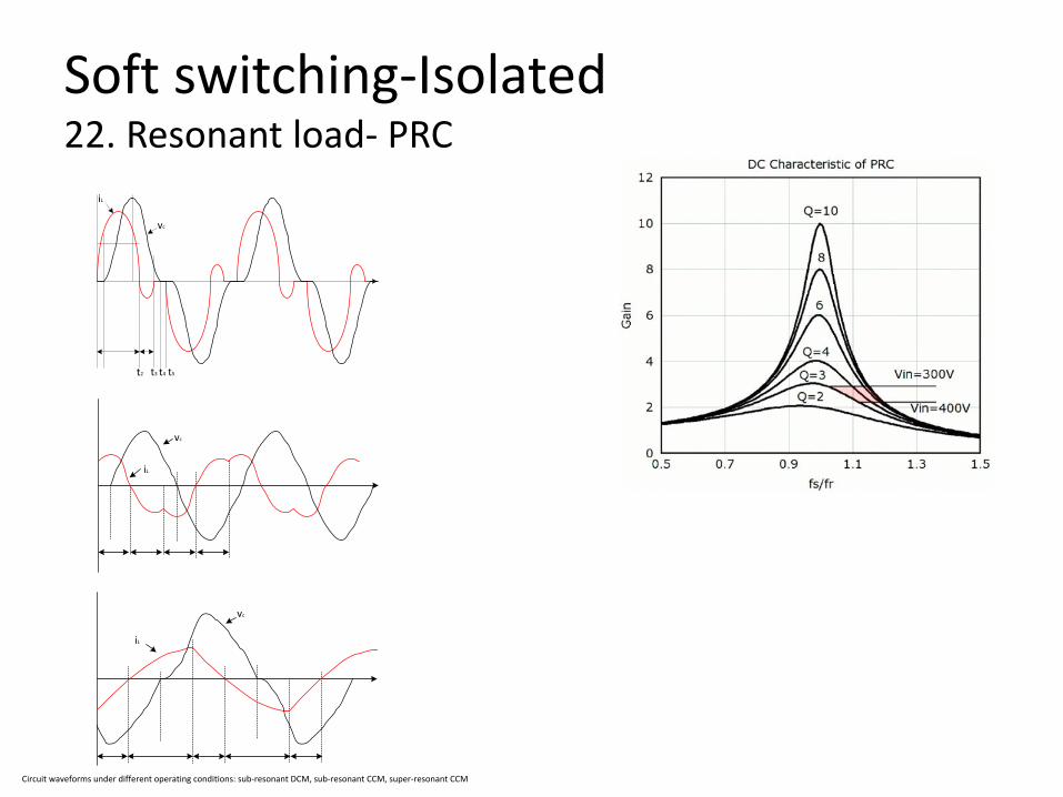
Soft switching-Isolated 22. Resonant load- PRC
t2 t3 t4 t5
iL
vc
iL
vc
vc
iL
Circuit waveforms under different operating conditions: sub-resonant DCM, sub-resonant CCM, super-resonant CCM

Soft switching-Isolated 23. Resonant load-LCC
LCC Converter
L
Cp
Cs

Soft switching-Isolated 23. Resonant load-LCC
TransistorDiode Transistor
Diode
Resonant capacitor voltage
Resonant current
Sub-Resonant Discontinuous conduction mode
Sub-resonant Continuous conduction mode
Transistor
Diode
Transistor
Diode
Transistor
Diode
Resonant capacitor voltage
Resonant current
Resonant capacitor voltage
Resonant current
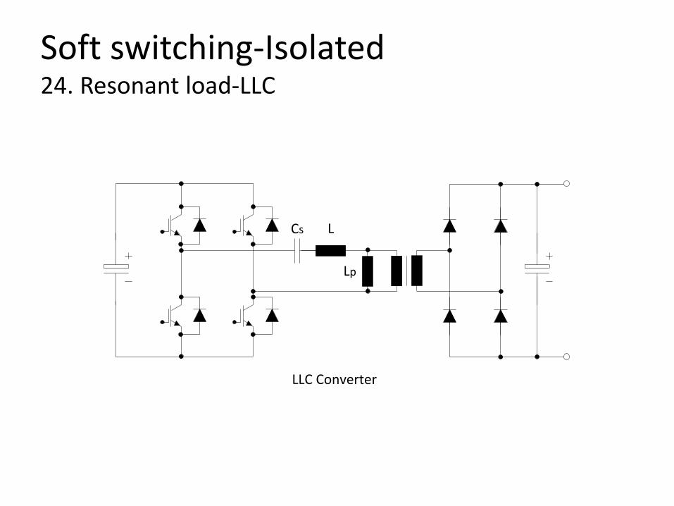
Soft switching-Isolated 24. Resonant load-LLC
LLC Converter
L
Lp
Cs

Soft switching-Isolated 24. Resonant load-LLC
Operation Waveforms for Capacitive and Inductive regions
Capacitive region
Peak gain
Inductive regionM
Fs
Vd
Ip
IDS1
Vd
Ip
IDS1
Reverse recovery ZVS
Soft switching-Isolated 24. Resonant load-LLC
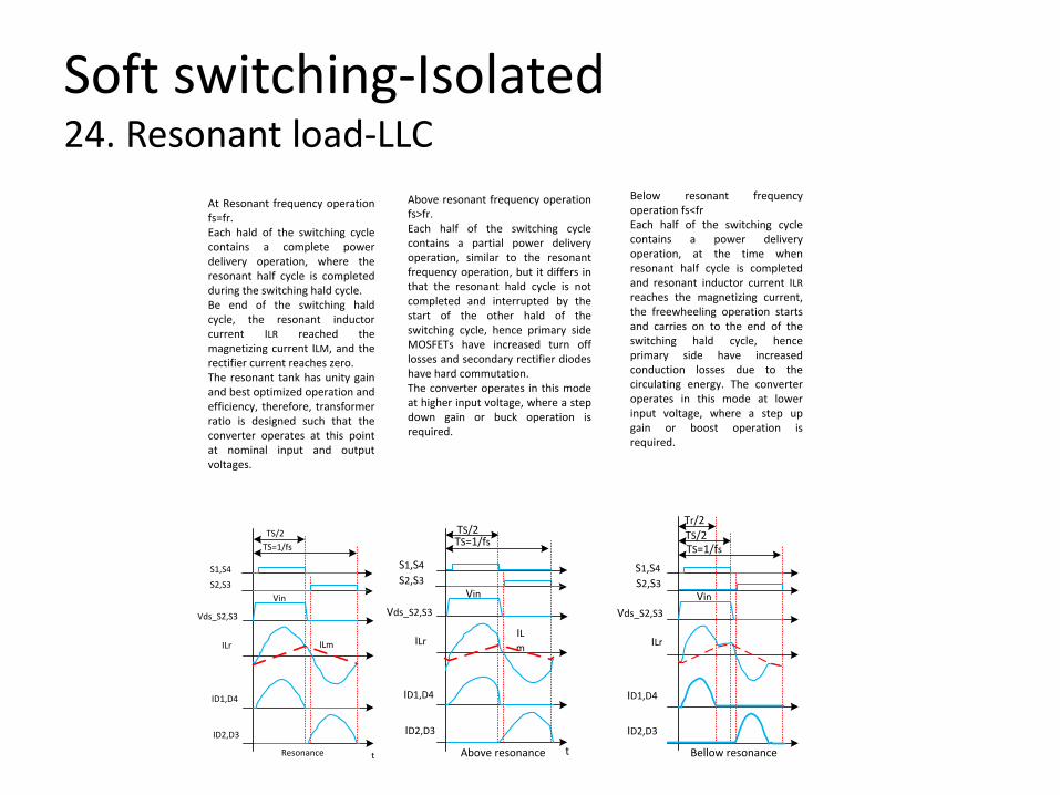
At Resonant frequency operation fs=fr.Each hald of the switching cycle contains a complete power delivery operation, where the resonant half cycle is completed during the switching hald cycle.Be end of the switching hald cycle, the resonant inductor current ILR reached the magnetizing current ILM, and the rectifier current reaches zero.The resonant tank has unity gain and best optimized operation and efficiency, therefore, transformer ratio is designed such that the converter operates at this point at nominal input and output voltages.
Above resonant frequency operation fs>fr.Each half of the switching cycle contains a partial power delivery operation, similar to the resonant frequency operation, but it differs in that the resonant hald cycle is not completed and interrupted by the start of the other hald of the switching cycle, hence primary side MOSFETs have increased turn off losses and secondary rectifier diodes have hard commutation.The converter operates in this mode at higher input voltage, where a step down gain or buck operation is required.
Below resonant frequency operation fs<frEach half of the switching cycle contains a power delivery operation, at the time when resonant half cycle is completed and resonant inductor current ILR reaches the magnetizing current, the freewheeling operation starts and carries on to the end of the switching hald cycle, hence primary side have increased conduction losses due to the circulating energy. The converter operates in this mode at lower input voltage, where a step up gain or boost operation is required.
Resonance
S1,S4
S2,S3
TS/2TS=1/fs
Vin
ILr ILm
Vds_S2,S3
ID1,D4
ID2,D3
t Above resonance
S1,S4S2,S3
TS/2TS=1/fs
Vin
ILrILm
Vds_S2,S3
ID1,D4
ID2,D3
t Bellow resonance
TS/2TS=1/fs
Tr/2
Vin
S1,S4S2,S3
Vds_S2,S3
ILr
ID1,D4
ID2,D3
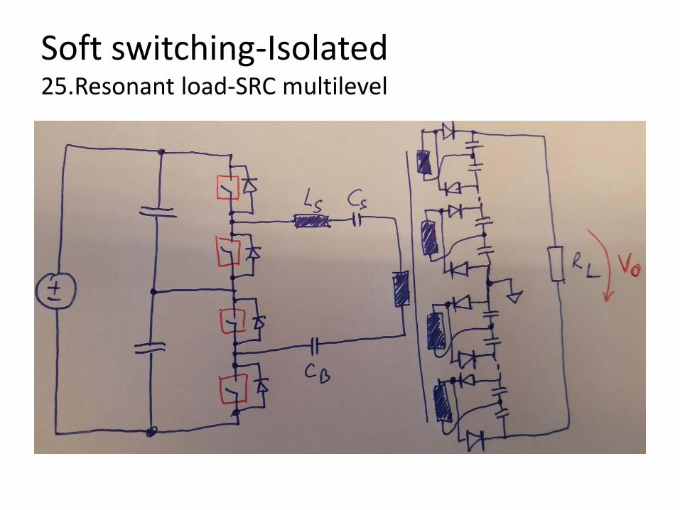
Soft switching-Isolated 25.Resonant load-SRC multilevel
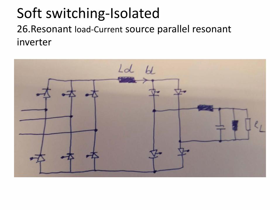
Soft switching-Isolated 26.Resonant load-Current source parallel resonant inverter

Soft switching-Isolated 27.Resonant load Class E converter
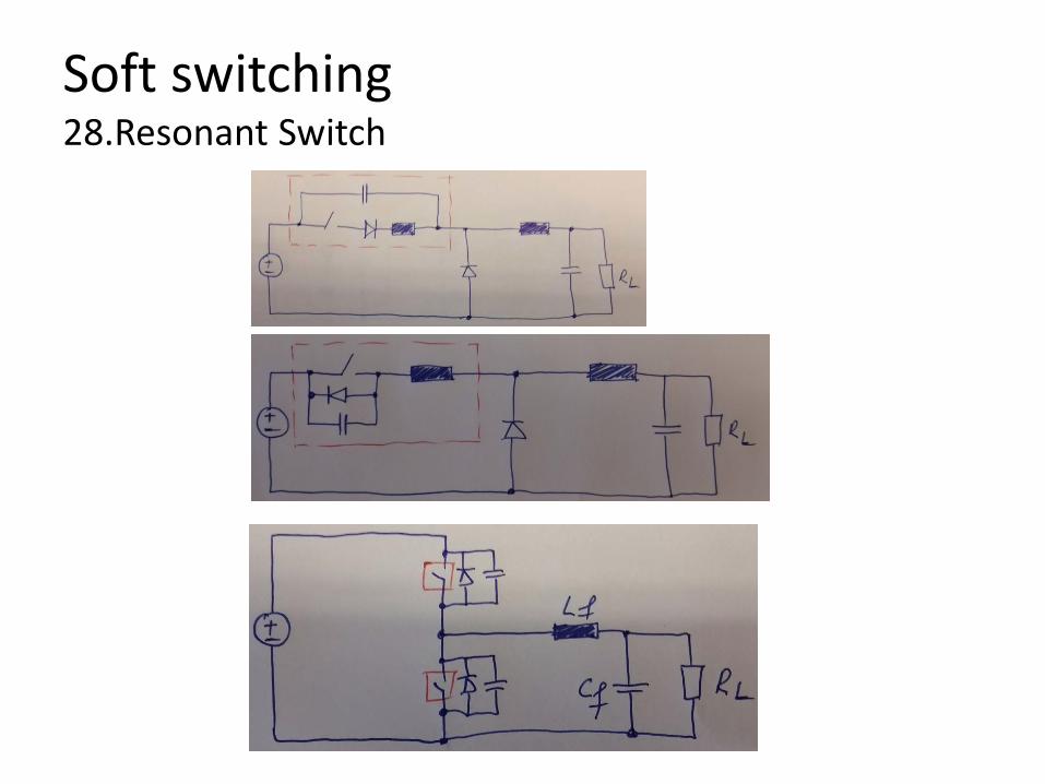
Soft switching 28.Resonant Switch

Soft switching 29.Resonant DC link

Soft switching-Isolated 30. Q2L MMC
SMSM
SMSM
SM
SM
Advantages: - two level operation with controllable values of voltage derivative, dv/dt - low cell capacitance requirements results in a considerable reduction in converter footprints - lower losses due to higher fundamental output voltage and the absence of a dc common mode component in converter arm currents, soft switching occurs owing to the dc -transformer topology; - beside flexibility of manufacturing and installation, the modular design results in additional output control capabilities; voltage magnitude control and selective harmonic elimination Disadvantages: - Control complexity - No galvanic separation - Suitable for smal voltage gain <2 - Unable to filter out dc current ripple

Soft switching-Non Isolated 31. Parallel Resonant
Jovcic 1phase step up resonant converter
Jovcic 3phase step up resonant converter

Soft switching-Non Isolated 31. Parallel Resonant
Advantages: - Simple converter topology - Soft switching - Use of thyristors Disadvantages: - No galvanic separation - High component stress on resonant tank and switches
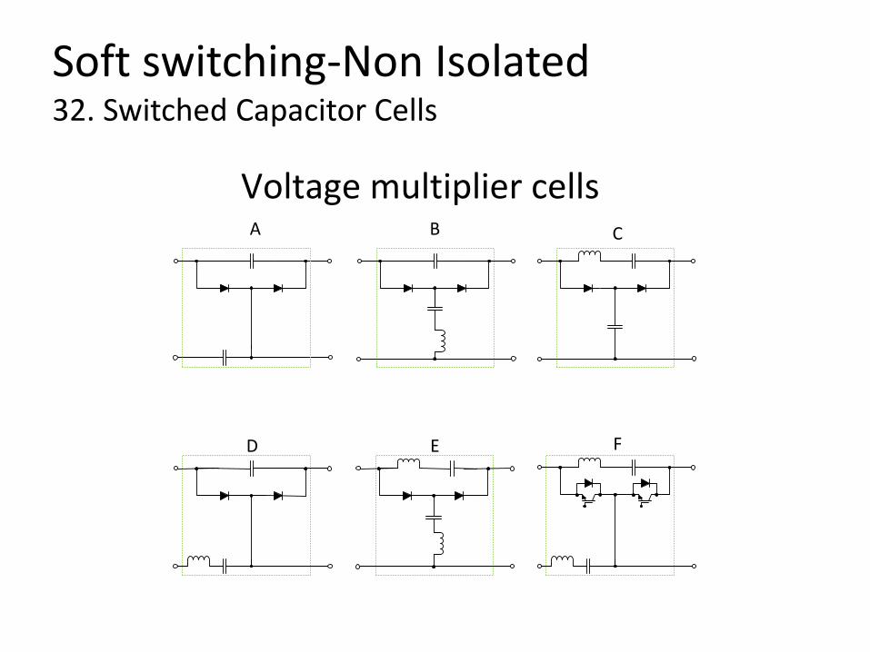
Soft switching-Non Isolated 32. Switched Capacitor Cells
A B C
FED
Voltage multiplier cells

Soft switching-Non Isolated 33. Boost with Voltage Multiplier
Boost with voltage multiplier
Voltage multiplier Cell #1
Voltage multiplier Cell #2
Voltage multiplier Cell #N

Soft switching-Non Isolated 34. ZCS RSC (Zero Current Switching Resonant Switched Capacitor)
Cell #1 Cell #2 Cell #N

Soft switching-Non Isolated 35. High gain RSC
Top cell
Bottom Cell
Cell #1 Cell #2 Cell #N
Soft switching-Non Isolated 35. High gain RSC Advantages: - Interleaved operation for low current ripple - Soft switching operation available at resonance - Improved voltage regulation (due to cascaded boost converter) - (A.Huang) Modular structure - (A.Huang) Low-voltage stress of the switches and reduced switching loss
Disadvantages: - Insulation to ground - No galvanic separation (unless provided in the cascaded converter) - Large ESR capacitors are preferable for low ripple - Suited mainly for low current applications - Voltage sag at higher stages (especially if many stages are used) - (A.Huang) Large number of capacitors, high passive component losses and large physical size are limiting the use in high-voltage gain offshore wind energy systems - The switched capacitor converters are modular, where each module increases outpu voltage only by the value of the input voltage. To achieve stepping ratio of say 10, nine capacitor modules are needed and over 18 switched, which implies significant losses and complexity. - Limited voltage capability for ZVS-RSC