High Power and high temperature type Power Relay …High Power and high temperature type Power Relay...
4
1 G 7 E B G7EB PCB Power Relays High Power and high temperature type Power Relay with 480 VAC 100 A current • 480 VAC/100 A high current switching capable • Ambient temperature 85°C • High impulse withstand voltage, 10 kV • Contact gap ≥3.6 mm (Applied to VDE0126) • Low initial contact resistance ≥5 mΩ Ordering Information Note. When ordering, add the rated coil voltage to the model number. Both the coil voltage on the product case and the packing will be marked as VDC. Raitings Coil Note 1. The rated current and resistance are measured at a coil temperature of 23°C with a tolerance of ±10%. Note 2. The operating characteristics are measured at a coil temperature of 23°C. Note 3. The maximum permissible voltage is the maximum value of the fluctuation range for the relay coil operating power supply and was measured at an ambient temperature of 23°C. * Power consumption with Holding Voltage is approx. 575 mW (when applying Holding Voltage at 45%). Please confirm the detail in page 4 Coil Voltage Reduction (Holding Voltage) after Relay Operation. * Some mounting direction is out of guarantee. Please confirm the detail in page 4 Mounting Direction. Contacts RoHS Compliant Terminal shape Contact form Enclosure rating Model Rated coil voltage (V) Minimum packing unit Standard SPST-NO (1a) Flux protection G7EB-1A 12 VDC 24 VDC 60pcs/box Special G7EB-1AP1 Rated voltage Rated current (mA) Coil resistance (Ω) Must operate voltage (V) Must release voltage (V) Max. voltage (V) Power consumption (mW) % of rated voltage 12 VDC Approx. 235.3 51 75% max. * 5 to 32% 120% (at 23°C) Approx. 2,800 Approx. 575 * 24 VDC Approx. 116.5 206 Item Resistive load Contact type Double Contact material Ag Alloy (Cd free) Rated load 100 A at 480 VAC 40 A at 800 VAC Rated carry current 100 A Max. switching voltage AC 800 V Max. switching current 100 A Application Examples • Power conditioner inverter • Industrial inverter • UPS Model Number Legend 1. Number of Poles 1: 1-pole 2. Contact Form A: SPST-NO (1a) 3. Terminal Shape None: Standard type P1: Special terminal type G7EB- 12 3 Rated coil voltage Example: G7EB-1A DC12
Transcript of High Power and high temperature type Power Relay …High Power and high temperature type Power Relay...

1
G7EB
G7EBPCB Power Relays
High Power and high temperature typePower Relay with 480 VAC 100 A current• 480 VAC/100 A high current switching capable
• Ambient temperature 85°C
• High impulse withstand voltage, 10 kV
• Contact gap ≥3.6 mm (Applied to VDE0126)
• Low initial contact resistance ≥5 mΩ
Ordering Information
Note. When ordering, add the rated coil voltage to the model number.
Both the coil voltage on the product case and the packing will be marked as VDC.
Raitings Coil
Note 1. The rated current and resistance are measured at a coil temperature of 23°C with a tolerance of ±10%.Note 2. The operating characteristics are measured at a coil temperature of 23°C.Note 3. The maximum permissible voltage is the maximum value of the fluctuation range for the relay coil operating power supply and was measured at an ambient
temperature of 23°C.* Power consumption with Holding Voltage is approx. 575 mW (when applying Holding Voltage at 45%). Please confirm the detail in page 4 Coil Voltage Reduction
(Holding Voltage) after Relay Operation.* Some mounting direction is out of guarantee. Please confirm the detail in page 4 Mounting Direction.
Contacts
RoHS Compliant
Terminal shape Contact form Enclosure rating Model Rated coil voltage (V) Minimum packing unit
StandardSPST-NO (1a) Flux protection
G7EB-1A 12 VDC24 VDC 60pcs/box
Special G7EB-1AP1
Rated voltage Rated current(mA)
Coil resistance(Ω)
Must operate voltage(V)
Must release voltage(V)
Max. voltage(V) Power consumption
(mW)% of rated voltage
12 VDC Approx. 235.3 5175% max. * 5 to 32% 120%
(at 23°C)Approx. 2,800Approx. 575 *24 VDC Approx. 116.5 206
Item Resistive load
Contact type Double
Contact material Ag Alloy (Cd free)
Rated load 100 A at 480 VAC 40 A at 800 VAC
Rated carry current 100 A
Max. switching voltage AC 800 V
Max. switching current 100 A
Application Examples• Power conditioner inverter• Industrial inverter• UPS
Model Number Legend
1. Number of Poles1: 1-pole
2. Contact FormA: SPST-NO (1a)
3. Terminal ShapeNone: Standard typeP1: Special terminal type
G7EB-1 2 3
Rated coil voltageExample: G7EB-1A DC12

2
G7EB PCB Power Relays
G7EB
Characteristics
Note. The values given above are initial values at 23°C. (Except Electrical Durability)*1. Measurement conditions: 6 VDC, 20 A, voltage drop method. *2. Measurement conditions: Applied rated coil voltage, no contact bouncing.*3. Measurement conditions: Measured with a 1,000 VDC megohmmeter at the same points as the dielectric strength was measured.*4. This specification is when diode and zener diode are used. For relay coil, please connect diode and zener diode.
For the detail, please refer to Diode Connection for Operating Coil on page 4.*5. The value was measured at a switching frequency of 180 operations/ minute.*6. For the detail of holding voltage usage, please refer to Coil Voltage Reduction (Holding Voltage) after Relay Operation on page 4.
Malfunction shock resistance
Item Model G7EB-1A/G7EB-1AP1
Contact resistance *1 5 mΩ max.
Operate time *2 30 ms max.
Release time *2 10 ms max.
Insulation resistance *3 1,000 MΩ min.
Dielectric strengthBetween coil and contacts 5,000 VAC, 50/60 Hz for 1 min
Between contacts of the same polarity 2,000 VAC, 50/60 Hz for 1 min
Impulse withstand voltage Between coil and contacts 10 kV (1.2 × 50 μs)
Vibration resistanceDestruction 10 to 55 to 10 Hz, 0.75 mm single amplitude (1.5 mm double amplitude)
Malfunction Excitation: 10 to 55 to 10 Hz, 0.75 mm single amplitude (1.5 mm double amplitude)No excitation: 10 to 55 to 10 Hz, 1.5 mm single amplitude (0.3 mm double amplitude)
Shock resistanceDestruction 1,000 m/s2
Malfunction Excitation: 100 m/s2
No excitation: 50 m/s2
Durability
Mechanical 1,000,000 operations min. (at 10,800 operations/h)
Electrical (Resistive) *4(1) 480 VAC 100 A 300 operations min. at 85°C(2) 800 VAC 40 A switch on, 100 A carry current, 40 A switch off; 30,000 operations min. at 85°C
(Switching frequency: 1 second ON - 9 seconds OFF)
Failure rate (P level) (Reference value) *5 1 A at 5 VDC
Use conditions
Coil holding voltage *6 45% to 65% of rated coil voltage
Ambient operating temperature -40°C to 85°C (with no icing or condensation)
Ambient operating humidity 5% to 85%
Weight Approx. 100 g
0
1,000X+
X-
Y+
Y-
Z+
Z-
1,000
1,000
1,000
600
800
200
60
400
1,000
1,000
ExcitationNo Excitation
Coil terminalContact terminal
Z+
x-
Y-
Y+
Z-
x+
Shock direction
Measurement:Measure the value of contact malfunction happening with applying 3 axes 6 direction 3 times each.The energized voltage is within the range of the rated holding voltage.
Standard value:Excitation 100 m/s2
No excitation 50 m/s2

3
G7EB PCB Power Relays
G7EB
Dimensions (Unit:mm)
Approval Standard
UL Recognized: (File No. E41515)
EN/IEC, TÜV Certificated: (Certificate No. R50416743)
CQC Certificated: (Certificate No. CQC18002207225)
Model Contact form Coil ratings Contact ratings Number of test operations
G7EB-1AG7EB-1AP1 SPST-NO(1a) 12, 24 VDC 800 VAC, 100 A carry current,
55 A switching off at 85°C 6,000
Model Contact form Coil ratings Contact ratings Number of test operations
G7EB-1AG7EB-1AP1 SPST-NO(1a) 12, 24 VDC 800 VAC, 100 A (Resistive) 200
Model Contact form Coil ratings Contact ratings Number of test operations
G7EB-1AG7EB-1AP1 SPST-NO(1a) 12, 24 VDC 800 VAC, 100 A (Resistive) 200
Please visit our website, which is noted on the last page.CAD Data
4
2 2
(BOTTOM VIEW) (BOTTOM VIEW)
PCB Mounting Holes Terminal Arrangement/Internal Connections
(No coil polarity)
*Average value
37.0 MAX.(36.7) *
0.8 2.7
50.5 MAX.(50) *
40.5 MAX. (40.2) *
40
25.9 4-3.8×3.1
16-R0.5 MIN.
2-1.5×3.2
8-R0.5 MIN.
Tolerance ±0.1
18.75
6.4
1.71.73
21
4
4
2 1.2(No coil polarity)
* Average value
37.0 MAX.(36.7) *
0.8 9.5
50.5 MAX.(50) *
40.5 MAX. (40.2) *
40
202-12×2.7
16-R0.5 MIN.
2-1.5×3.2
8-R0.5 MIN.Tolerance ±0.1
19.2
6.8
3
21
4
(BOTTOM VIEW) (BOTTOM VIEW)
PCB Mounting Holes Terminal Arrangement/Internal Connections
Standard type G7EB-1A
Special terminal type G7EB-1AP1
CAD Data
CAD Data
4
G7EB PCB Power Relays
G7EB
PrecautionsPlease refer to "PCB Relays Common Precautions" for correct use.
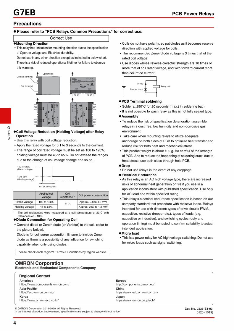
Mounting Direction• This relay has limitation for mounting direction due to the specification
of Operate voltage and Electrical durability.Do not use in any other direction except as indicated in below chart.There is a risk of reduced operational lifetime for failure to observe this warning.
Coil Voltage Reduction (Holding Voltage) after Relay Operation
• Use this relay with coil voltage reduction.• Apply the rated voltage for 0.1 to 3 seconds to the coil first.• The range of coil rated voltage must be set as 100 to 120%,
holding voltage must be 45 to 65%. Do not exceed the ranges due to the change of coil voltage change and so on.
* The coil resistances were measured at a coil temperature of 23°C withtolerances of ± 10%.
Diode Connection for Operating Coil• Connect diode or Zener diode (or Varistor) to the coil. (refer to
the picture below).Diode is for coil surge absorption. Ensure to include Zener diode as there is a possibility of any influence for switching capability when only using diodes.
• Coils do not have polarity, so put diodes as it becomes reserve direction with applied voltage for coils.
• The recommended Zener diode voltage is 3 times that of the rated coil voltage.
• Use diodes whose reverse dielectric strength are 10 times or more that of coil rated voltage, and with forward current more than coil rated current.
PCB Terminal soldering• Solder at 290°C for 20 seconds (max.) in soldering bath.• It is not possible to wash relay as this is not fully sealed type.Assembly• To reduce the risk of specification deterioration assemble
relays in a dust free, low humidity and non-corrosive gas environment.
• Take care when mounting relays to utilize adequate anchorage on both sides of PCB to optimize heat transfer and reduce risk for both heat and mechanical stress.
• This product weight is about 100 g. Be careful of the strength of PCB. And to reduce the happening of soldering crack due to heat stress, use both sides through hole PCB.
Drop• Do not use relays in the event of any droppage.Electrical Endurance• As this relay is an AC high voltage type, there are increased
risks of abnormal heat generation or fire if you use in a application inconsistent with published specification. Use only for AC load and within specified rating.
• This relay's electrical endurance specification is based on our company standard test procedure with resistive loads. Relays intended for use with different; types of drive circuits PWM, capacitive, resistive dropper etc.), types of loads (e.g. capacitive or inductive), and switching cycles (duty and operation timing) must be tested to confirm suitability to actual intended application.
Micro load• This is a power relay for AC high voltage switching. Do not use
for micro loads such as signal switching.
Correct Use
Applied coil voltage
Coil resistance * Coil power consumption
Rated voltage 100 to 120%51 Ω
Approx. 2.8 to 4.0 mW
Holding voltage 45 to 65% Approx. 0.57 to 1.2 mW
Contact terminalUpper side
Coil terminal
100 to 120%
45 to 65%(Holding voltage)
0.1 to 3 seconds
(Rated voltage)
Relay coilDiode
Zenner diode
Please check each region's Terms & Conditions by region website.
OMRON CorporationElectronic and Mechanical Components Company
Regional Contact
Cat. No. J236-E1-030120 (1019)
Americas Europehttps://www.components.omron.com/ http://components.omron.eu/
Asia-Pacific China https://ecb.omron.com.sg/ https://www.ecb.omron.com.cn/
Korea Japanhttps://www.omron-ecb.co.kr/ https://www.omron.co.jp/ecb/
In the interest of product improvement, specifications are subject to change without notice.© OMRON Corporation 2019-2020 All Rights Reserved.