High Position Resolution and High Dynamic Range Stripline...
5
HIGH POSITION RESOLUTION AND HIGH DYNAMIC RANGE STRIPLINE BEAM POSITION MONITOR (BPM) READOUT SYSTEM FOR THE KEKB INJECTOR LINAC TOWARDS THE SuperKEKB R. Ichimiya # , T. Suwada, M. Satoh, F. Miyahara, K. Furukawa, KEK, Tsukuba, Japan Abstract The SuperKEKB accelerator is now being upgraded to bring the world highest luminosity (L=8x10 35 /cm 2 /s). Hence, the KEKB injector linac has to produce low emit- tance and high charge electron (20 mm mrad, 7 GeV/c 2 , 5 nC) and positron (20 mm mrad, 4 GeV/c 2 , 4 nC) beam, respectively. In order to achieve these criteria, the accel- erator structure has to be aligned within 0.1 mm position error. Since BPMs are essential instruments for beam based alignment (BBA), it is required to have one magni- tude better position resolution to get enough alignment results. We have begun to develop high position resolu- tion BPM readout system with narrow bandpass filters (fc = 180 MHz) and 250 MSa/s 16-bit ADCs. It handles two bunches with 96 ns interval separately and has a dynamic range from 0.1 nC to 10 nC. To compensate circuit drift, two calibration (x-direction and y-direction) pulses are output to the BPM electrodes between beam cycles (20 ms). Since it needs to achieve not only high position resolution but also good position accuracy, overall non- linearity within ±0.02 dB is required and the system has to have more than ±5 mm accurate position range. We confirmed the system performance with a 3-BPM resolu- tion tests at KEK Injector Linac and it turned out that the system has 3 μm position resolution. We plan to install this system during 2015 summer shutdown. INTRODUCTION KEK Injector Linac is now being upgraded as a part of SuperKEKB accelerator complex [1] to achieve L = 8x10 35 /cm 2 /s luminosity, both electron and positron beam emittance have to be 20 mm mrad. To perform the BBA stably, BPMs are required to have one magnitude better position resolution than the required alignment accuracy. To accomplish <10 μm position resolution, we have designed dedicated narrow bandpass filter (BPF) type readout circuitry with 250 MSa/s 16 bit pipeline ADC (AD9467-250 [2]). As the SuperKEKB injector injects electron / positron beams into four different energy rings (SuperKEKB HER/LER, PF and PF-AR) simulta- neously, we employed electrical attenuators to keep enough dynamic range. * BPM readout system has to have not only high position resolution (σ < 10 μm) but also good position accuracy. There are many sources of position error, especially input channel gain drift from each BPM electrode is one of dominant sources. To compensate this, calibration pulse generator [3] is implemented. A calibration pulse from one electrode is equally divided into adjacent electrodes * [email protected] with coupling capacitance (see Fig. 1). By calculating both channel output power, channel gain ratio can be monitored and compensated. Figure 1: BPM calibration scheme is illustrated. Calibra- tion tone is provided to the top electrode and induced pulses are generated on both adjacent electrodes with coupling capacitance. HARDWARE IMPLEMENTATION Baseline design of this BPM readout system has been reported at previous IBIC2013 conference [4]. Hence, we report updates from the last design here. As discussed in previous section, we need to handle the signal with high linearity to achieve target position reso- lution (σ < 10 μm). It turned out that first prototype has following rooms to be improved: At first, helical coils are needed to precise tuning, so it is not suitable for high linearity application. Therefore, we changed BPF centre frequency to 180 MHz so that we can use normal LC filters. Figure 2 shows the photograph of the prototype of the BPM readout board, Figure 3 shows block diagram of 2nd prototype BPF board. The latter BPF performs waveform shaping (burst length = 60 ns) and limits the bandwidth (22 MHz). The former BPF (BW=60 MHz) is for anti-aliasing at the ADC. In addition, the latter amplifier is the critical device that limits the overall linearity. Therefore, we tested three RF amplifiers shown in Table 2. As shown in Fig. 4 an ADL5536 (Analog Devices (AD)), which have the high- est output third-order intercept point (OIP3), has optimal (flat) linearity. Figure 5 shows the BPF output waveform and ADC sampled data points. Waveform is stretched to about Proceedings of IBIC2014, Monterey, CA, USA WEPD04 BPMs and Beam Stability Wednesday poster session ISBN 978-3-95450-141-0 637 Copyright © 2014 CC-BY-3.0 and by the respective authors
Transcript of High Position Resolution and High Dynamic Range Stripline...

HIGH POSITION RESOLUTION AND HIGH DYNAMIC RANGE STRIPLINE BEAM POSITION MONITOR (BPM) READOUT SYSTEM FOR
THE KEKB INJECTOR LINAC TOWARDS THE SuperKEKB
R. Ichimiya#, T. Suwada, M. Satoh, F. Miyahara, K. Furukawa, KEK, Tsukuba, Japan
Abstract The SuperKEKB accelerator is now being upgraded to
bring the world highest luminosity (L=8x1035/cm2/s). Hence, the KEKB injector linac has to produce low emit-tance and high charge electron (20 mm mrad, 7 GeV/c2, 5 nC) and positron (20 mm mrad, 4 GeV/c2, 4 nC) beam, respectively. In order to achieve these criteria, the accel-erator structure has to be aligned within 0.1 mm position error. Since BPMs are essential instruments for beam based alignment (BBA), it is required to have one magni-tude better position resolution to get enough alignment results. We have begun to develop high position resolu-tion BPM readout system with narrow bandpass filters (fc = 180 MHz) and 250 MSa/s 16-bit ADCs. It handles two bunches with 96 ns interval separately and has a dynamic range from 0.1 nC to 10 nC. To compensate circuit drift, two calibration (x-direction and y-direction) pulses are output to the BPM electrodes between beam cycles (20 ms). Since it needs to achieve not only high position resolution but also good position accuracy, overall non-linearity within ±0.02 dB is required and the system has to have more than ±5 mm accurate position range. We confirmed the system performance with a 3-BPM resolu-tion tests at KEK Injector Linac and it turned out that the system has 3 μm position resolution. We plan to install this system during 2015 summer shutdown.
INTRODUCTION KEK Injector Linac is now being upgraded as a part of
SuperKEKB accelerator complex [1] to achieve L = 8x1035 /cm2/s luminosity, both electron and positron beam emittance have to be 20 mm mrad. To perform the BBA stably, BPMs are required to have one magnitude better position resolution than the required alignment accuracy. To accomplish <10 μm position resolution, we have designed dedicated narrow bandpass filter (BPF) type readout circuitry with 250 MSa/s 16 bit pipeline ADC (AD9467-250 [2]). As the SuperKEKB injector injects electron / positron beams into four different energy rings (SuperKEKB HER/LER, PF and PF-AR) simulta-neously, we employed electrical attenuators to keep enough dynamic range.*
BPM readout system has to have not only high position resolution (σ < 10 μm) but also good position accuracy. There are many sources of position error, especially input channel gain drift from each BPM electrode is one of dominant sources. To compensate this, calibration pulse generator [3] is implemented. A calibration pulse from one electrode is equally divided into adjacent electrodes
with coupling capacitance (see Fig. 1). By calculating both channel output power, channel gain ratio can be monitored and compensated.
Figure 1: BPM calibration scheme is illustrated. Calibra-tion tone is provided to the top electrode and induced pulses are generated on both adjacent electrodes with coupling capacitance.
HARDWARE IMPLEMENTATION Baseline design of this BPM readout system has been
reported at previous IBIC2013 conference [4]. Hence, we report updates from the last design here.
As discussed in previous section, we need to handle the signal with high linearity to achieve target position reso-lution (σ < 10 μm). It turned out that first prototype has following rooms to be improved:
At first, helical coils are needed to precise tuning, so it is not suitable for high linearity application. Therefore, we changed BPF centre frequency to 180 MHz so that we can use normal LC filters. Figure 2 shows the photograph of the prototype of the BPM readout board, Figure 3 shows block diagram of 2nd prototype BPF board. The latter BPF performs waveform shaping (burst length = 60 ns) and limits the bandwidth (22 MHz). The former BPF (BW=60 MHz) is for anti-aliasing at the ADC.
In addition, the latter amplifier is the critical device that limits the overall linearity. Therefore, we tested three RF amplifiers shown in Table 2. As shown in Fig. 4 an ADL5536 (Analog Devices (AD)), which have the high-est output third-order intercept point (OIP3), has optimal (flat) linearity.
Figure 5 shows the BPF output waveform and ADC sampled data points. Waveform is stretched to about
Proceedings of IBIC2014, Monterey, CA, USA WEPD04
BPMs and Beam StabilityWednesday poster session
ISBN 978-3-95450-141-0637 Co
pyrig
ht©
2014
CC-B
Y-3.
0an
dby
ther
espe
ctiv
eaut
hors

60 ns length (<96 ns) so that enough data points can be sampled. 180 MHz as BPF center frequency locates at 250 MHz ADC[2]’s 2nd Nyquist zone (Under sampling condition).
Figure 2: An photograph of prototype of BPM readout board (called 18K12A) is shown. This is a double width module. A BPF board is attached on bottom of a main (ADC) board. The output from BPF board is fed to themain board via four coaxial cables.
Then, we changed ADC input circuit from active circuit (with a RF amplifier) to passive circuit (with transform-ers) not to limit the linearity.
In addition, we took following improving steps to in-crease effective number of bits (ENOBs) of the ADC, which relates to the position resolution: 1. It is known that smaller ADC clock jitter contributes
higher ENOBs. Hence, we changed standard AT cut crystal oscillator to SAW oscillator (known as low jit-ter output).
2. Eliminates ADC Clock delay chip (EP195) that gives additional clock jitter.
Finally, we increased calibration pulse generator output
power to more than 40 dBm so that we can get enough S/N with the large inner diameter BPM for positron (ϕ = 63 mm, normal BPM has ϕ = 27 mm).
Table 1: Design Differences
d d d
age has an electrical attenua-
Figure 4: Amplifier linearity curve in the BPF circuitry is shown. AD (Blue) shows wide linearity, Avago (Red)shows moderate characteristics and RFMD (Yellow) shows narrow linearity.
Figure 3: Block diagram of Band Pass Filter board (one channel is shown). It equips calibration pulse input selec-tor. First Butterworth filter (60 MHz) cut tails that exceeADC’s Nyquist window (125 MHz – 250 MHz) ansecond Bessel filter (22 MHz) forms total bandwidth anburst length (60 ns). Each sttor and an amplifier to set an adequate level.
Prototype 1st (18K12) 2nd (18K12A)
BPF Fre-quency
300 MHz 180 MHz
BPF struc-ture
Bessel Filter with helical coils + anti-aliasing filter
Bessel filter with LC + Butter-worth filter for anti-aliasing
Cal. power > 36 dBm > 40 dBm
ADC Clock AT cut SAW (low jitter)
Clock delay Yes No
ADC Input Active circuit Passive circuit
WEPD04 Proceedings of IBIC2014, Monterey, CA, USA
ISBN 978-3-95450-141-0638Co
pyrig
ht©
2014
CC-B
Y-3.
0an
dby
ther
espe
ctiv
eaut
hors
BPMs and Beam StabilityWednesday poster session

Table 2: Amplifier Comparison
Device P1dB Gain OIP3 NF Technology
SBB5089Z (RFMD) [5] 20 dB 20.8 dB 37.5 dB 4.3 dB InGaP HBT.
ADL5536 (AD) [6] 19.6 dB 19.8 dB 45.0 dB 2.6 dB GaAs HBT.
MGA-30689 (Avago) [7] 22.4 dB 14.3 dB 43.0 dB 3.0 dB GaAs pHEMT.
Figure 5: (a) BPF output waveform and (b) ADC sampled data points (2nd Nyquist zone under sampling).
PERFORMANCE TEST
Linearity / Resolution Check In order to estimate linearity and position resolution of
the BPM readout system, we performed linearity and resolution test. Instead of beam emulated impulse genera-tor signal, 180 MHz CW is used. Because we’d like to keep the signal level stable as much as possible. Since accurate signal level is the key of these test, we used an Agilent J7211B Step attenuator, which has 0.03 dB re-peatability. We calibrated it with a network analyzer. To provide beam equivalent ADC sampled data points, we used 96 ns Hanning window, which gives similar wave-form with Fig. 5 (b).
Figure 6 shows test results with this setup: position res-olution (upper plot) and channel power linearity (lower plot). At best condition, we can get about 1 μm position resolution. However, actual beam passes through at offset position from the BPM center, which gives unequal chan-nel power between opposite channels. Therefore, we have to set an appropriate operation point, which allows ±5 mm position range (14 dB range is required).
Our requirement conditions for this system are: 1. Position resolution is less than 10 μm, 2. Linearity is within ±0.02 dB.
We find 24 dB ranges is agreed to these condition in the Fig. 6, so we can set an appropriate operation point that allows ±5 mm position range.
Amplifier Gain Time Drift For the BPF output amplifier candidates, we also meas-
ured amplifier gain time drift in a thermostatic chamber (25±0.1°C) for 286 hours (11.9 days). Measurement results are shown in Fig. 7. Although each channel power time drift ratio is up to 1.6% order, this is very curious phenomenon that these amplifiers have long time range gain drift even they are stored in a thermostat-ic chamber.
MGA-30689 (Avago) shows largest gain drift (1.6% (0.14 dB) / 11.9 days). On the other hand, ADL5536 (Analog Devices) shows smallest gain drift (0.6% (0.05 dB) / 11.9 days). Only MGA-30689 has pHEMT (FFT structure) and ADL5536 and SBB5089 have HBT (Bipolar structure). The difference of the am-plifier structure may contribute these gain drift differ-ences.
With this result and linearity measurements discussed in the previous section, we have decided to employ the ADL5536 for the BPF amplifier.
200 mV 20 ns
Proceedings of IBIC2014, Monterey, CA, USA WEPD04
BPMs and Beam StabilityWednesday poster session
ISBN 978-3-95450-141-0639 Co
pyrig
ht©
2014
CC-B
Y-3.
0an
dby
ther
espe
ctiv
eaut
hors

Figure 6: Upper plot shows BPM readout system resolu-tion at ideal condition. Lower plot shows system lineari-ty: we have 24 dB with ±0.02 dB linearity range.
Figure 7: Amplifier gain drift is shown. Vertical axis is normalized channel power and horizontal axis is elapsed time. DUTs were tested in a thermostatic chamber.
3-BPM Resolution Tests In order to make a decision to fabricate this readout
system, we performed a 3-BPM resolution tests at KEK Linac. We used adjacent three BPMs (SP52-4, SP54-4 and SP56-4).
When we assume linear lattice, arbitrary three BPM positions x1, x2 and x3 are given as:
Here, we can get (A, B, C) with a multiple regression
analysis from N set of (x1n, x2n, x3n ) with N-times trials. Therefore residual can be given (corresponds to Fig. 8 right) :
Assuming three BPM’s position resolutions are same, the position resolution is given:
We took 3500 events data at 12.5 Hz, with changing
Y steering magnet current in each 500 events. Figure 8 shows (left) reconstructed position to measured position, (right) residual distribution.
From the last formula and data, we got 3 μm position resolution.
SUMMARY AND FUTURE PLAN We have developed a BPM readout system with high
position resolution (σ < 10 μm) and high accuracy with a gain calibration system. In order to achieve these criteria, high linearity (±0.02 dB linearity) and large dynamic range (>14 dB) is required. We performed 3-BPM resolution tests to demonstrate the readout system can be used at real environment and we got 3 �m position resolution.
We plan to fabricate total 100 units within this fiscal year (till March 2015) and install at 2015 summer shut-down.
ACKNOWLEDGMENT Through this BPM readout system development, we
thank Dr. Steve Smith, Dr. Andrew Young at SLAC and Dr. Makoto Tobiyama at KEK for their kind suggestions and advice in design and development. We also thank Mr. Kyosuke Yamada of Digitex Lab. Co. Ltd. (PCB), Mr. Morishige Aoyama of Sanko-sha Inc. (RF) and Mr. Takehito Koui of Skywave Co. Ltd. (FPGA) for de-veloping this readout system with us.
.
1.
1
.
WEPD04 Proceedings of IBIC2014, Monterey, CA, USA
ISBN 978-3-95450-141-0640Co
pyrig
ht©
2014
CC-B
Y-3.
0an
dby
ther
espe
ctiv
eaut
hors
BPMs and Beam StabilityWednesday poster session
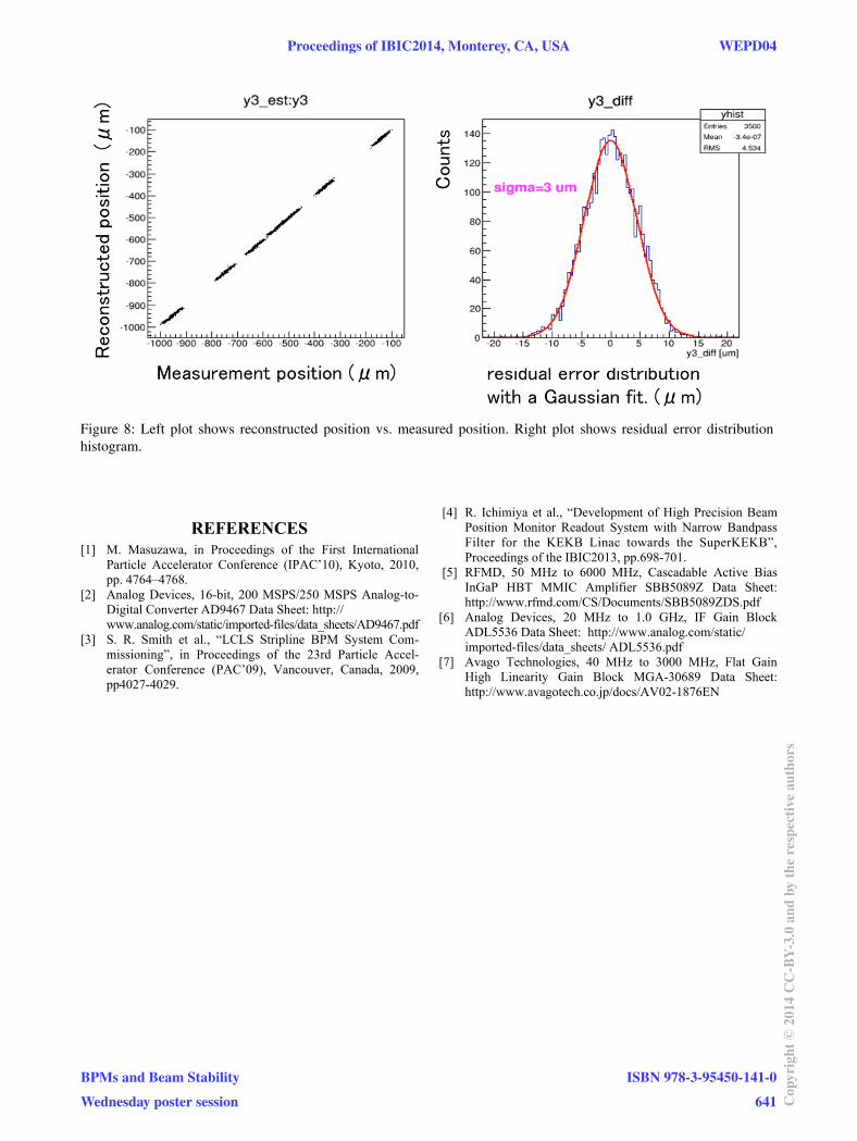
Figure 8: Left plot shows reconstructed position vs. measured position. Right plot shows residual error distribution histogram.
REFERENCES [1] M. Masuzawa, in Proceedings of the First International
Particle Accelerator Conference (IPAC’10), Kyoto, 2010, pp. 4764–4768.
[2] Analog Devices, 16-bit, 200 MSPS/250 MSPS Analog-to-Digital Converter AD9467 Data Sheet: http://www.analog.com/static/imported-files/data_sheets/AD9467.pdf
[3] S. R. Smith et al., “LCLS Stripline BPM System Com-missioning”, in Proceedings of the 23rd Particle Accel-erator Conference (PAC’09), Vancouver, Canada, 2009, pp4027-4029.
[4] R. Ichimiya et al., “Development of High Precision Beam Position Monitor Readout System with Narrow Bandpass Filter for the KEKB Linac towards the SuperKEKB”, Proceedings of the IBIC2013, pp.698-701.
[5] RFMD, 50 MHz to 6000 MHz, Cascadable Active Bias InGaP HBT MMIC Amplifier SBB5089Z Data Sheet: http://www.rfmd.com/CS/Documents/SBB5089ZDS.pdf
[6] Analog Devices, 20 MHz to 1.0 GHz, IF Gain Block ADL5536 Data Sheet: http://www.analog.com/static/imported-files/data_sheets/ ADL5536.pdf
[7] Avago Technologies, 40 MHz to 3000 MHz, Flat Gain High Linearity Gain Block MGA-30689 Data Sheet: http://www.avagotech.co.jp/docs/AV02-1876EN
Proceedings of IBIC2014, Monterey, CA, USA WEPD04
BPMs and Beam StabilityWednesday poster session
ISBN 978-3-95450-141-0641 Co
pyrig
ht©
2014
CC-B
Y-3.
0an
dby
ther
espe
ctiv
eaut
hors