High-Performance Wireless Interface for Implant-to-Air ...
128
High-Performance Wireless Interface for Implant-to-Air Communications Thèse Hadi Bahramiabrghouei Doctorat en génie électrique Philosophiæ doctor (Ph.D.) Québec, Canada © Hadi Bahramiabrghouei, 2015
Transcript of High-Performance Wireless Interface for Implant-to-Air ...

High-Performance Wireless Interface forImplant-to-Air Communications
Thèse
Hadi Bahramiabrghouei
Doctorat en génie électriquePhilosophiæ doctor (Ph.D.)
Québec, Canada
© Hadi Bahramiabrghouei, 2015

Résumé
Nous élaborons une interface cerveau-machine (ICM) entièrement sans fil afin de fournir un sys-tème de liaison directe entre le cerveau et les périphériques externes, permettant l’enregistrementet la stimulation du cerveau pour une utilisation permanente. Au cours de cette thèse, nous ex-plorons la modélisation de canal, les antennes implantées et portables en tant que propagateursappropriés pour cette application, la conception du nouveau système d’un émetteur-récepteurUWB implantable, la conception niveau système du circuit et sa mise en œuvre par un procédéCMOS TSMC 0.18 µm. En plus, en collaboration avec Université McGill, nous avons conçuun réseau de seize antennes pour une détection du cancer du sein à l’aide d’hyperfréquences.
Notre première contribution calcule la caractérisation de canal de liaison sans fil UWB d’implantà l’air, l’absorption spécifique moyennée (ASAR), et les lignes directrices de la FCC sur la den-sité spectrale de puissance UWB transmis. La connaissance du comportement du canal estnécessaire pour déterminer la puissance maximale permise à 1) respecter les lignes directricesANSI pour éviter des dommages aux tissus et 2) respecter les lignes directrices de la FCC surles transmissions non autorisées. Nous avons recours à un modèle réaliste du canal biologiqueafin de concevoir les antennes pour l’émetteur implanté et le récepteur externe. Le placementdes antennes est examiné avec deux scénarios contrastés ayant des contraintés de puissance.La performance du système au sein des tissus biologiques est examinée par l’intermédiaire dessimulations et des expériences.
Notre deuxième contribution est dédiée à la conception des antennes simples et à doublepolarisation pour les systèmes d’enregistrement neural sans fil à bande ultra-large en utilisantun modèle multicouches inhomogène de la tête humaine. Les antennes fabriquées à partirde matériaux flexibles sont plus facilement adaptées à l’implantation ; nous étudions desmatériaux à la fois flexibles et rigides et examinons des compromis de performance. Lesantennes proposées sont conçues pour fonctionner dans une plage de fréquence de 2-11 GHz(ayant S11-dessous de -10 dB) couvrant à la fois la bande 2.45 GHz (ISM) et la bande UWB3.1-10.6 GHz. Des mesures confirment les résultats de simulation et montrent que les antennesflexibles ont peu de dégradation des performances en raison des effets de flexion (en termes decorrespondance d’impédance). Finalement, une comparaison est réalisée entre quatre antennesimplantables, couvrant la gamme 2-11 GHz : 1) une rigide, à la polarisation simple, 2) une
iii

rigide, à double polarisation, 3) une flexible, à simple polarisation et 4) une flexible, à doublepolarisation. Dans tous les cas une antenne rigide est utilisée à l’extérieur du corps, avecune polarisation appropriée. Plusieurs avantages ont été confirmés pour les antennes à lapolarisation double : 1) une taille plus petite, 2) la sensibilité plus faible aux désalignementsangulaires, et 3) une plus grande fidélité.
Notre troisième contribution fournit la conception niveau système de l’architecture de com-munication sans fil pour les systèmes implantés qui stimulent simultanément les neurones etenregistrent les réponses de neurones. Cette architecture prend en charge un grand nombred’électrodes (> 500), fournissant 100 Mb/s pour des signaux de stimulation de liaison descen-dante, et Gb/s pour les enregistrements de neurones de liaison montante. Nous proposons unearchitecture d’émetteur-récepteur qui partage une antenne ultra large bande, un émetteur-récepteur simplifié, travaillant en duplex intégral sur les deux bandes, et un nouveau formeurd’impulsions pour la liaison montante du Gb/s soutenant plusieurs formats de modulation.Nous présentons une démonstration expérimentale d’ex vivo de l’architecture en utilisant descomposants discrets pour la réalisation les taux Gb/s en liaison montante. Une bonne per-formance de taux d’erreur de bit sur un canal biologique à 0,5, 1 et 2 Gb/s des débits dedonnées pour la télémétrie de liaison montante (UWB) et 100 Mb/s pour la télémétrie enliaison descendante (bande 2.45 GHz) est atteinte.
Notre quatrième contribution présente la conception au niveau du circuit d’un dispositifd’émission en duplex total qui est présentée dans notre troisième contribution. Ce dispo-sitif d’émission en duplex total soutient les applications d’interfaçage neural multimodal eten haute densité (les canaux de stimulant et d’enregistrement) avec des débits de donnéesasymétriques. L’émetteur (TX) et le récepteur (RX) partagent une seule antenne pour ré-duire la taille de l’implant. Le TX utilise impulse radio ultra-wide band (IR-UWB) basé surune approche alliant des bords, et le RX utilise un nouveau 2.4 GHz récepteur on-off keying(OOK).Une bonne isolation (> 20 dB) entre le trajet TX et RX est mis en œuvre 1) par miseen forme des impulsions transmises pour tomber dans le spectre UWB non réglementé (3.1-7GHz), et 2) par un filtrage espace-efficace du spectre de liaison descendante OOK dans unamplificateur à faible bruit RX. L’émetteur UWB 3.1-7 GHz peut utiliser soit OOK soit lamodulation numérique binaire à déplacement de phase (BPSK). Le FDT proposé offre unedouble bande avec un taux de données de liaison montante de 500 Mbps TX et un taux dedonnées de liaison descendante de 100 Mb/s RX, et il est entièrement en conformité avec lesstandards TSMC 0.18 µm CMOS dans un volume total de 0,8 mm2. Ainsi, la mesure deconsommation d’énergie totale en mode full duplex est de 10,4 mW (5 mW à 100 Mb/s pourRX, et de 5,4 mW à 500 Mb/s ou 10,8 PJ / bits pour TX).
Notre cinquième contribution est une collaboration avec l’Université McGill dans laquellenous concevons des antennes simples et à double polarisation pour les systèmes de détectiondu cancer du sein à l’aide d’hyperfréquences sans fil en utilisant un modèle multi-couche et
iv

inhomogène du sein humain. Les antennes fabriquées à partir de matériaux flexibles sontplus facilement adaptées à des applications portables. Les antennes flexibles miniaturiséesmonopôles et spirales sur un 50 µm Kapton polyimide sont conçus, en utilisant high frequencystructure simulator (HFSS), à être en contact avec des tissus biologiques du sein. Les antennesproposées sont conçues pour fonctionner dans une gamme de fréquences de 2 à 4 GHz. Lesmesures montrent que les antennes flexibles ont une bonne adaptation d’impédance dans lesdifférentes positions sur le sein. De Plus, deux antennes à bande ultralarge flexibles 4 × 4(simple et à double polarisation), dans un format similaire à celui d’un soutien-gorge, ont étédéveloppés pour un système de détection du cancer du sein basé sur le radar.
v

Abstract
We are working on a fully wireless brain-machine-interface to provide a communication linkbetween the brain and external devices, enabling recording and stimulating the brain forpermanent usage. In this thesis we explore channel modeling, implanted and wearable anten-nas as suitable propagators for this application, system level design of an implantable UWBtransceiver, and circuit level design and implementing it by TSMC 0.18 µm CMOS process.Also, in a collaboration project with McGill University, we designed a flexible sixteen antennaarray for microwave breast cancer detection.
Our first contribution calculates channel characteristics of implant-to-air UWB wireless link,average specific absorption rate (ASAR), and FCC guidelines on transmitted UWB powerspectral density. Knowledge of channel behavior is required to determine the maximum al-lowable power to 1) respect ANSI guidelines for avoiding tissue damage and 2) respect FCCguidelines on unlicensed transmissions. We utilize a realistic model of the biological chan-nel to inform the design of antennas for the implanted transmitter and the external receiver.Antennas placement is examined under two scenarios having contrasting power constraints.Performance of the system within the biological tissues is examined via simulations and ex-periments.
Our second contribution deals with designing single and dual-polarization antennas for wirelessultra-wideband neural recording systems using an inhomogeneous multi-layer model of thehuman head. Antennas made from flexible materials are more easily adapted to implantation;we investigate both flexible and rigid materials and examine performance trade-offs. Theproposed antennas are designed to operate in a frequency range of 2–11 GHz (having S11below -10 dB) covering both the 2.45 GHz (ISM) band and the 3.1–10.6 GHz UWB band.Measurements confirm simulation results showing flexible antennas have little performancedegradation due to bending effects (in terms of impedance matching). Finally, a comparisonis made of four implantable antennas covering the 2-11 GHz range: 1) rigid, single polarization,2) rigid, dual polarization, 3) flexible, single polarization and 4) flexible, dual polarization. Inall cases a rigid antenna is used outside the body, with an appropriate polarization. Severaladvantages were confirmed for dual polarization antennas: 1) smaller size, 2) lower sensitivityto angular misalignments, and 3) higher fidelity.
vii

Our third contribution provides system level design of wireless communication architecture forimplanted systems that simultaneously stimulate neurons and record neural responses. Thisarchitecture supports large numbers of electrodes (>500), providing 100 Mb/s for the downlinkof stimulation signals, and Gb/s for the uplink neural recordings. We propose a transceiverarchitecture that shares one ultra-wideband antenna, a streamlined transceiver working atfull-duplex on both bands, and a novel pulse shaper for the Gb/s uplink supporting severalmodulation formats. We present an ex-vivo experimental demonstration of the architectureusing discrete components achieving Gb/s uplink rates. Good bit error rate performance overa biological channel at 0.5, 1, and 2 Gbps data rates for uplink telemetry (UWB) and 100Mbps for downlink telemetry (2.45 GHz band) is achieved.
Our fourth contribution presents circuit level design of the novel full-duplex transceiver (FDT)which is presented in our third contribution. This full-duplex transceiver supports high-densityand multimodal neural interfacing applications (high-channel count stimulating and recording)with asymmetric data rates. The transmitter (TX) and receiver (RX) share a single antennato reduce implant size. The TX uses impulse radio ultra-wide band (IR-UWB) based on anedge combining approach, and the RX uses a novel 2.4-GHz on-off keying (OOK) receiver.Proper isolation (>20 dB) between the TX and RX path is implemented 1) by shaping thetransmitted pulses to fall within the unregulated UWB spectrum (3.1-7 GHz), and 2) by space-efficient filtering (avoiding a circulator or diplexer) of the downlink OOK spectrum in the RXlow-noise amplifier. The UWB 3.1-7 GHz transmitter can use either OOK or binary phaseshift keying (BPSK) modulation schemes. The proposed FDT provides dual band 500-MbpsTX uplink data rate and 100 Mbps RX downlink data rate, and it is fully integrated intostandard TSMC 0.18 µm CMOS within a total size of 0.8 mm2. The total measured powerconsumption is 10.4 mW in full duplex mode (5 mW at 100 Mbps for RX, and 5.4 mW at 500Mbps or 10.8 pJ/bit for TX).
Our fifth contribution is a collaboration project with McGill University which we design sin-gle and dual-polarization antennas for wireless ultra-wideband breast cancer detection systemsusing an inhomogeneous multi-layer model of the human breast. Antennas made from flexiblematerials are more easily adapted to wearable applications. Miniaturized flexible monopoleand spiral antennas on a 50 µm Kapton polyimide are designed, using a high frequency struc-ture simulator (HFSS), to be in contact with biological breast tissues. The proposed antennasare designed to operate in a frequency range of 2–4 GHz (with reflection coefficient (S11) be-low -10 dB). Measurements show that the flexible antennas have good impedance matchingwhile in different positions with different curvature around the breast. Furthermore, two flex-ible conformal 4×4 ultra-wideband antenna arrays (single and dual polarization), in a formatsimilar to that of a bra, were developed for a radar-based breast cancer detection system.
viii

Contents
Résumé iii
Abstract vii
Contents ix
List of Tables xiii
List of Figures xv
Remerciements xxi
Abbreviations xxiii
symbols xxv
Remerciements xxvii
1 Introduction 11.1 Multi-layer Model of Biological Tissues in EM Software . . . . . . . . . . . 3
1.1.1 Human Head . . . . . . . . . . . . . . . . . . . . . . . . . . . . . . . 31.1.2 Breast . . . . . . . . . . . . . . . . . . . . . . . . . . . . . . . . . . . 4
1.2 Classification of Implantable and Wearable Antenna . . . . . . . . . . . . . 51.2.1 Dipole Antenna . . . . . . . . . . . . . . . . . . . . . . . . . . . . . 61.2.2 Monopole Antenna . . . . . . . . . . . . . . . . . . . . . . . . . . . . 61.2.3 Loop Antenna . . . . . . . . . . . . . . . . . . . . . . . . . . . . . . 71.2.4 Single Arm Spiral Antenna . . . . . . . . . . . . . . . . . . . . . . . 71.2.5 Summary of Antennas . . . . . . . . . . . . . . . . . . . . . . . . . . 7
1.3 System Level Design Flow . . . . . . . . . . . . . . . . . . . . . . . . . . . 71.3.1 Selection of Operation Frequency Band . . . . . . . . . . . . . . . . 71.3.2 Consideration of Propagation Channel Model . . . . . . . . . . . . . 81.3.3 Link Budget Estimation . . . . . . . . . . . . . . . . . . . . . . . . 81.3.4 Modulation and Demodulation Scheme Design . . . . . . . . . . . . 91.3.5 Circuit Level Design . . . . . . . . . . . . . . . . . . . . . . . . . . . 9
1.4 Thesis Outline . . . . . . . . . . . . . . . . . . . . . . . . . . . . . . . . . . 9
2 Biological Channel Modeling and Implantable UWB Antenna Design 132.1 Introduction . . . . . . . . . . . . . . . . . . . . . . . . . . . . . . . . . . . . 132.2 Channel Modeling Under Two Scenarios . . . . . . . . . . . . . . . . . . . . 15
ix

2.2.1 Multi-layer Model of Tissues . . . . . . . . . . . . . . . . . . . . . . 152.2.2 Near-field Behavior . . . . . . . . . . . . . . . . . . . . . . . . . . . . 17
2.3 Antenna Design . . . . . . . . . . . . . . . . . . . . . . . . . . . . . . . . . . 182.4 Simulated Performance . . . . . . . . . . . . . . . . . . . . . . . . . . . . . . 19
2.4.1 Radiation and Return Loss . . . . . . . . . . . . . . . . . . . . . . . 192.4.2 Federal Communication Committee (FCC) . . . . . . . . . . . . . . 202.4.3 Specific Absorption Rate (SAR) . . . . . . . . . . . . . . . . . . . . 202.4.4 System Performance . . . . . . . . . . . . . . . . . . . . . . . . . . . 21
2.5 Fabrication and Measured Performance . . . . . . . . . . . . . . . . . . . . . 222.5.1 Network Analyzer Measurements . . . . . . . . . . . . . . . . . . . . 232.5.2 Anechoic Chamber Measurements . . . . . . . . . . . . . . . . . . . 23
2.6 Potential for High Data Rate . . . . . . . . . . . . . . . . . . . . . . . . . . 262.7 Conclusion . . . . . . . . . . . . . . . . . . . . . . . . . . . . . . . . . . . . 27
3 Flexible, Polarization-Diverse UWB Antennas for Implantable NeuralRecording Systems 293.1 Introduction . . . . . . . . . . . . . . . . . . . . . . . . . . . . . . . . . . . . 293.2 Modelling and Methodology . . . . . . . . . . . . . . . . . . . . . . . . . . . 303.3 Antenna Design . . . . . . . . . . . . . . . . . . . . . . . . . . . . . . . . . . 31
3.3.1 Single-Polarization Antennas . . . . . . . . . . . . . . . . . . . . . . 323.3.2 Dual-Polarization Antennas . . . . . . . . . . . . . . . . . . . . . . . 32
3.4 Simulation and Measurement of S-Parameters . . . . . . . . . . . . . . . . . 343.4.1 Measurement Setup . . . . . . . . . . . . . . . . . . . . . . . . . . . 343.4.2 Flexible Single- and Dual-Polarization Antennas . . . . . . . . . . . 353.4.3 Comparing Flexible and Rigid Antennas . . . . . . . . . . . . . . . . 37
3.5 Near-Field Characteristics of Antennas . . . . . . . . . . . . . . . . . . . . . 383.5.1 Specific Absorption Rate (ASAR) . . . . . . . . . . . . . . . . . . . . 383.5.2 Power Efficiency . . . . . . . . . . . . . . . . . . . . . . . . . . . . . 383.5.3 Fidelity Factor of the Near-field Links . . . . . . . . . . . . . . . . . 403.5.4 Figure of Merit (FoM) . . . . . . . . . . . . . . . . . . . . . . . . . . 413.5.5 Bending Effect . . . . . . . . . . . . . . . . . . . . . . . . . . . . . . 42
3.6 Conclusion . . . . . . . . . . . . . . . . . . . . . . . . . . . . . . . . . . . . 42
4 System Level Design of High-Speed Full-Duplex Transceiver for NeuralRecording and Stimulating Systems 454.1 Introduction . . . . . . . . . . . . . . . . . . . . . . . . . . . . . . . . . . . . 454.2 System Architecture . . . . . . . . . . . . . . . . . . . . . . . . . . . . . . . 47
4.2.1 Diplexer . . . . . . . . . . . . . . . . . . . . . . . . . . . . . . . . . . 484.2.2 UWB Pulse Shaping . . . . . . . . . . . . . . . . . . . . . . . . . . . 484.2.3 Antenna Design . . . . . . . . . . . . . . . . . . . . . . . . . . . . . . 494.2.4 Average Specific Absorption Rate (ASAR) . . . . . . . . . . . . . . 50
4.3 Experimental Proof-of-Concept . . . . . . . . . . . . . . . . . . . . . . . . . 504.4 Experimental Results . . . . . . . . . . . . . . . . . . . . . . . . . . . . . . . 53
4.4.1 BPSK Modulation . . . . . . . . . . . . . . . . . . . . . . . . . . . . 544.4.2 DPSK Modulation . . . . . . . . . . . . . . . . . . . . . . . . . . . . 544.4.3 OOK Modulation . . . . . . . . . . . . . . . . . . . . . . . . . . . . 55
4.5 Data Rates and BER Performance . . . . . . . . . . . . . . . . . . . . . . . 554.6 Conclusion . . . . . . . . . . . . . . . . . . . . . . . . . . . . . . . . . . . . 59
x

5 A Fully Integrated Full-Duplex High Speed Transceiver for Multi-SitesStimulating and Recording Neural Implants 615.1 Introduction . . . . . . . . . . . . . . . . . . . . . . . . . . . . . . . . . . . . 615.2 System overview . . . . . . . . . . . . . . . . . . . . . . . . . . . . . . . . . 635.3 Full-Duplex Transceiver Design . . . . . . . . . . . . . . . . . . . . . . . . . 64
5.3.1 UWB Transmitter Design . . . . . . . . . . . . . . . . . . . . . . . . 655.3.2 2.4-GHz Receiver Design . . . . . . . . . . . . . . . . . . . . . . . . . 66
5.4 Full-Duplex Transceiver Measurement Results . . . . . . . . . . . . . . . . . 685.5 Conclusion . . . . . . . . . . . . . . . . . . . . . . . . . . . . . . . . . . . . 75
6 Flexible Sixteen Antenna Array for Microwave Breast Cancer Detection 776.1 Introduction . . . . . . . . . . . . . . . . . . . . . . . . . . . . . . . . . . . . 776.2 Inhomogeneous Breast Modelling . . . . . . . . . . . . . . . . . . . . . . . . 806.3 Flexible Antenna Array . . . . . . . . . . . . . . . . . . . . . . . . . . . . . 81
6.3.1 Single- and Dual-Polarization Antennas . . . . . . . . . . . . . . . . 816.4 Measurement Results . . . . . . . . . . . . . . . . . . . . . . . . . . . . . . . 83
6.4.1 Measurement Setup . . . . . . . . . . . . . . . . . . . . . . . . . . . 836.4.2 S-parameter Results . . . . . . . . . . . . . . . . . . . . . . . . . . . 83
6.5 Improving Penetration of Propagated EM Waves Inside Breast and Maxi-mum Allowed Transmitted Power . . . . . . . . . . . . . . . . . . . . . . . . 836.5.1 Improving Penetration of Propagated EM Waves . . . . . . . . . . . 856.5.2 Maximum Allowed Transmitted Power by the Antennas . . . . . . . 87
6.6 Conclusion . . . . . . . . . . . . . . . . . . . . . . . . . . . . . . . . . . . . 88
7 Conclusions and Future Work 89
Publication List 91
Bibliography 93
xi


List of Tables
2.1 The best and worst cases of the parietal lobe region of the human head in mm. 15
3.1 Characteristics of TX and RX antennas . . . . . . . . . . . . . . . . . . . . . . 373.2 Near-field characteristic of the TX antennas . . . . . . . . . . . . . . . . . . . . 42
4.1 Average transmitted power at .001 BER for different receiver sensitivities for500 Mb/s uplink and 100 Mb/s downlink . . . . . . . . . . . . . . . . . . . . . 59
5.1 Comparison of previously published data links with our approaches. . . . . . . 75
6.1 Characteristic of TX and RX antennas. . . . . . . . . . . . . . . . . . . . . . . 816.2 Maximum averaged transmitted power for monopole and spiral antennas in
various array positions. . . . . . . . . . . . . . . . . . . . . . . . . . . . . . . . 88
xiii


List of Figures
1.1 An overview of an implanted neural recording and stimulating system and itsapplications. . . . . . . . . . . . . . . . . . . . . . . . . . . . . . . . . . . . . . 3
1.2 Human head model in HFSS software. . . . . . . . . . . . . . . . . . . . . . . . 41.3 (a) Relative permittivity εr of different tissues in the human head, (b) Loss
tangent of different tissues in the human head [1]. . . . . . . . . . . . . . . . . . 41.4 Human breast model in HFSS software. . . . . . . . . . . . . . . . . . . . . . . 51.5 (a) Relative permittivity εr of different tissues in the human breast, (b) Loss
tangent of different tissues in the human breast [1]. . . . . . . . . . . . . . . . . 51.6 Different small antennas for implantable and wearable application . . . . . . . . 6
2.1 a) E-field intensity at 3 GHz in the multi-layer model, (b) E-field intensitybeyond the Z-Y plane. . . . . . . . . . . . . . . . . . . . . . . . . . . . . . . . . 16
2.2 Simulated parameters for implanted antennas (a) directivty at broadside direc-tion (b) gain at broadside direction. . . . . . . . . . . . . . . . . . . . . . . . . 21
2.3 Simulated S11 for the antennas (a) the worst case (b) the best case. . . . . . . . 212.4 Simulated parameters for the antennas for two scenarios and best case and worst
case (a) amplitude of the channel, (b) phase of the channel, and (c) group delayof the channel. . . . . . . . . . . . . . . . . . . . . . . . . . . . . . . . . . . . . 22
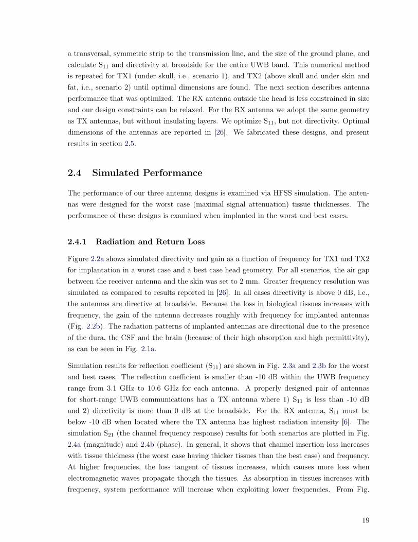
2.5 Simulated ASAR for different tissues (a) position under skull (b) above skull. . 222.6 The fabricated antennas (a) radiator side, (b) ground plane side, (c) implanted
antenna covered with an insulating layer (Al2O3 ceramic substrate (εr = 9.8)),and (d) illustration of connection of implanted antenna to integrated recordingchip. . . . . . . . . . . . . . . . . . . . . . . . . . . . . . . . . . . . . . . . . . . 24
2.7 Setup for S-parameter measurement; A and B mimic biological model for sce-narios 1 and 2, respectively; C and D are screen shots of transmission losses forscenarios 1 and 2 respectively. . . . . . . . . . . . . . . . . . . . . . . . . . . . . 24
2.8 Comparison of simulated and measured return losses (a) the TX antenna forscenario1, (b) the TX antenna for scenario 2, and (c) the RX antenna. . . . . . 25
2.9 Comparison of simulated and measured (a) amplitude of the channel, (b) phaseof the channel, and (c) group delay characteristic of scenario 1 and scenario 2. . 25
2.10 Comparison of measured and simulated radiation pattern in the XZ plane andYZ plane for 7 GHz. . . . . . . . . . . . . . . . . . . . . . . . . . . . . . . . . . 27
2.11 Measured radiation efficiency of the TX antennas at broadside (φ= 0, θ= 0) forscenario 1 and 2. . . . . . . . . . . . . . . . . . . . . . . . . . . . . . . . . . . . 28
3.1 Propagation behavior of E field intensity around the implanted antenna in Z-Yplane (referenced to 1 W transmitted power by the antenna). . . . . . . . . . . 31
xv

3.2 Simulated axial ratio of the dual polarization flexible TX and rigid RX antennas. 333.3 The induced current on the antennas (a) TX, (b) RX for the single-polarization
antennas, (c) TX, and (d) RX for the dual-polarization antennas. . . . . . . . . 343.4 S-parameter measurement (a) Block diagram of the set-up, and (b) the set-up,
for S-parameter measurements. . . . . . . . . . . . . . . . . . . . . . . . . . . . 353.5 Set up for characterizing sensitivity to angular misalignment between TX and
RX antennas (a) single-polarization antennas, and (b) dual-polarization antennas. 363.6 Simulated and measured S-parameters for implanted flexible antennas for dif-
ferent angular missalignment between TX and RX (a, c) single-polarization,and (b, d) dual-polarization. . . . . . . . . . . . . . . . . . . . . . . . . . . . . . 36
3.7 Comparison of the measured results of the antennas (a) S21, and (b) group delay. 383.8 The simulated ASAR of the implanted antennas and calculated allowable max-
imum transmitted power (PMax) for (a) rigid, single-polarization (PMax =3.5 mW), (b) rigid, dual-polarization (PMax = 3.9 mW), (c) flexible, single-polarization (PMax = 3.5 mW), and (d) flexible, dual-polarization (PMax =5.7 mW). . . . . . . . . . . . . . . . . . . . . . . . . . . . . . . . . . . . . . . . 39
3.9 (a) Waveform of the Gaussian modulated sine wave described by (3.1), and (b)its spectrum. . . . . . . . . . . . . . . . . . . . . . . . . . . . . . . . . . . . . . 40
3.10 Distorted received pulse which is calculated based on the measured S21 forantennas with (a) flexible, dual-polarization, (b) flexible, single-polarization,(c) rigid, single-polarization, and (d) rigid dual-polarization. . . . . . . . . . . . 41
3.11 Comparison of measured S11 (A, C) for zero bending of the flexible TX antennasand (B, D) for 30 degree bending of the flexible TX antennas. . . . . . . . . . . 43
4.1 Brain-machine interface solutions: (a) conventional architecture with separateuplink transmitter and downlink receivers, and (b) the proposed full-duplex,dual-band transceiver. . . . . . . . . . . . . . . . . . . . . . . . . . . . . . . . . 46
4.2 Radiated E-field while implant and external antennas are communicating throughbiological tissues in Z-Y plane in HFSS. . . . . . . . . . . . . . . . . . . . . . . 50
4.3 (a) Block digram of the system level implementation of the proposed link, and(b) the measured frequency response of the wireless channel. . . . . . . . . . . . 52
4.4 Set-up for data communications. . . . . . . . . . . . . . . . . . . . . . . . . . . 534.5 Measurment result: (a) OOK modulation waveform in AWG output for 500
Mbps (b) its spectrum. . . . . . . . . . . . . . . . . . . . . . . . . . . . . . . . 534.6 Reciver blocks implemented in MATLAB (off-line processing) for (a) BPSK,
(b) DPSK, and (c) OOK. . . . . . . . . . . . . . . . . . . . . . . . . . . . . . . 544.7 Different stages of data transmission for (a) BPSK uplink, (b) DPSK uplink,
(c) OOK uplink, and (d) OOK downlink. . . . . . . . . . . . . . . . . . . . . . 564.8 BER for downlink and uplink. Red arrows are SNR penalties at 10−3. Results
are for (a) 500 Mb/s uplink, (b) 1Gb/s uplink, (c) 2 Gb/s uplink, and (d) 100Mbps downlink link. Defference from Q-function between BPSK and DPSK orBPSK and OOK are 1 dB and 3 dB, respectively. . . . . . . . . . . . . . . . . . 57
5.1 Block diagram of an implantable neural recording and stimulating device in-cluding an inductive power link and the proposed full duplex transceiver. . . . 64
5.2 The integrated circuit building blocks of the proposed implantable wireless in-terface consists of a new full duplex data transceiver. . . . . . . . . . . . . . . . 65
xvi
5.3 Up-link a) transmitter circuit enabling to generate UWB signal for transmit-ting data using OOK and BPSK modulations, and b) size and power efficienttransmitter circuit enabling to produce OOK signal. . . . . . . . . . . . . . . . 66
5.4 Schematic of the downlink 2.4 GHz receiver front-end which includes a lownoise amplifier and a mixer based on current starving. The simulated gain(S21), input matching (S11), output matching (S22), and noise figure (NF) ofthe LNA are shown. . . . . . . . . . . . . . . . . . . . . . . . . . . . . . . . . . 67
5.5 The chip micrograph of the proposed full duplex transceiver fabricated in aTSMC 0.18 µm CMOS technology, with a total die size of 1×0.8 mm2. . . . . . 68
5.6 a) Experimental setup block diagram showing the required equipment, and b)the experimental measurement setup employed for characterizing the full-duplexdata link. . . . . . . . . . . . . . . . . . . . . . . . . . . . . . . . . . . . . . . . 69
5.7 The measured spectrums of the UWB output signals for a) transmitter TX1,and b) transmitter TX2. . . . . . . . . . . . . . . . . . . . . . . . . . . . . . . . 71
5.8 Measurement results of the full duplex transceiver including a) the transmittedUWB signals using OOK and BPSK modulation schemes (TX1 and TX2) at arate of 500 Mbps, and b) the generated 2.4 GHz OOK signal and detected dataat a rate of 100 Mbps. . . . . . . . . . . . . . . . . . . . . . . . . . . . . . . . . 72
5.9 Block diagram of the UWB receivers (RX-UWB) for a) OOK, and b) BPSKmodulations. The measured eye diagrams for the transmitters TX1 in c) OOKmode, d) BPSK mode, and e) TX2 in OOK mode. . . . . . . . . . . . . . . . . 73
5.10 The measured power consumption of the UWB transmitters for OOK and BPSKmodulations as a function of data rate. . . . . . . . . . . . . . . . . . . . . . . . 74
6.1 An overview of a flexible antenna array as a bra for breast cancer detection(single arm spiral and monopole antenna arrays. . . . . . . . . . . . . . . . . . 79
6.2 Multi-layer inhomogeneous model of the breast for designing the flexible an-tenna array in HFSS. . . . . . . . . . . . . . . . . . . . . . . . . . . . . . . . . . 80
6.3 The induced current on the flexible single polarization antenna. . . . . . . . . . 826.4 The induced current on the flexible dual polarization antenna. . . . . . . . . . . 826.5 The S-parameter measurement set up a) Antenna array placed on the dielectric
tissue-mimicking phantom, and b) Top view of the array, identifying the nipplelocation. . . . . . . . . . . . . . . . . . . . . . . . . . . . . . . . . . . . . . . . . 84
6.6 The measured S11 for different positions of the antennas in the array (a) monopoleantenna, and (b) single arm spiral antenna. . . . . . . . . . . . . . . . . . . . . 85
6.7 The measured S21 between antenna 3 of array 1 and antennas 1 to 4 of array2 and 3 (a) amplitude for monopole antenna array, (c) phase for monopoleantenna array (c) amplitude for spiral antenna array, and (d) phase for spiralantenna array. . . . . . . . . . . . . . . . . . . . . . . . . . . . . . . . . . . . . 86
6.8 The real part of the Poynting vector propagating in the Z-X plane for antenna4: without reflector (left side) and with reflector (right side) for a) monopoleand b) spiral antenna arrays; color map applies to all cases. . . . . . . . . . . . 87
xvii


Abbreviations
AWG Arbitrary Wave GeneratorANSI American National Standards InstituteASAR Average Specific Absorption RateASK Amplitude Shift KeyingBMI Brain Machine InterfaceBER Bit Error RateBPSK Binary Phase Shift KeyingCMOS Complementary Metal Oxide SemiconductorCS Common SourceCSF Cerebrospinal FluidCPW Coplanar WaveguideDPSK Differential Phase Shift KeyingEM Electro-MagneticFCC Federal Communications CommissionFSK Frequency Shift KeyingFDT Full-Duplex TransceiverFoM Figure of MeritHFSS High Frequency Structure SimulatorISM Industrial, Scientific and MedicalIR-UWB Impulse Radio Ultra-Wide BandISI Inter-Symbol InterferenceLO Local OscillatorLNA Low Noise AmplifierMI Microwave ImagingMT Microwave TomographyMB-OFDM Multi-Band Orthogonal Frequency-Division MultiplexingMPPM Multiple Pulse Position ModulationNF Noise FigureOOK On-Off Keying
xix

PSK Phase Shift KeyingPRBS Pseudo-Random Binary SequencePCB Printed Circuit BoardRX ReceiverSNR Signal-to-Noise RatioSMA Sub-Miniature version ATSMC Taiwan Semiconductor Manufacturing CompanyTX TransmitterVLSI Very-Large-Scale Integration
xx

List of Symbols
λ Wavelengthθ1 Half-Power Beam-Width of Radiation Pattern in Horizontalθ2 Half-Power Beam-Width of Radiation Pattern in VerticalD0 Directivity Peak at BroadsideGt Maximum GainPt Maximum Transmitted Powerτ(ω) Group DelayD Biggest Dimension of the Effective AntennaA(ω) Amplitude of Frequency Responseθ(ω) Phase of Frequency ResponseH(ω) Frequency ResponseF FidelitySr(t) Actual Received Waveform from One Pair Antennar(t) Received Pulse from an Ideal Wireless Linkt0 Offset Time Domain of Gaussian Pulseτ Standard Deviation of Gaussian Distributionf0 Center Frequency of Gaussian-Modulated Sinusoidal WaveformV (t) Gaussian-Modulated Sinusoidal WaveformEy E field in y DirectionEx E field in x DirectionΩ OhmJ Joule (Unit of Energy)W Watt (Unit of Power)Wav Time Average Poynting VectorS21 Reflection CoefficientS11 Transmission Coefficient
xxi

To my family
xxii

Acknowledgement
First and foremost, I would like to thank Prof. Leslie Ann Rusch for guiding my research,allowing me to discover several topics, and providing me the resources to carry it out. Sheencouraged me to perform to the best of my abilities and gave me opportunities to learndifferent topics. I would never have had these opportunities if I had not joined her group.I will never forget her lessons and all that she did for me. I would also like to thank Prof.Benoit Gosselin for his advice and guidance. I had this opportunity to work closely with himon his brain machine interface project.
I also thank the members of my reading and oral committee, for their comments and thoughtson this thesis. They have all demonstrated an outstanding passion for their work, whichtranslates into great understanding of their respective fields that easily comes across duringmy conversations with them.
I am also grateful to Prof. Dominic Grenier for letting us to use his lab and measurementequipment. I am also deeply thankful for Prof. Paul Fortier and Prof. Milica Popovich fortheir guidance and advice. I would also like to thank my team members Seyed AbdullahMirbozorgi, Emily Porter, and Reza Ameli for their corporation, help and support throughthe research. I am greatly indebted to Dr. Nguyen, Mr. Chretien and Mr. Gagnon for theirassistance and corporation.
Finally, I am deeply grateful to my parents and my family for their endless encouragement.This work could not have been accomplished without their dedicated support, trust, and lovethroughout my life.
xxiii


Foreword
Five chapters of this thesis are composed of material already published in technical Transac-tions. In the thesis, text have been modified to be consistent with the rest of the document.The introduction sections have been most heavily modified. Here, I detail my contributionsto five published papers.
Paper 1: H. Bahrami, S. A. Mirbozorgi, L. A. Rusch, and B. Gosselin, “Biological Chan-nel Modeling and Implantable UWB Antenna Design for Neural Recording Systems,” IEEETransactions on Biomedical Engineering, (Accepted, 2014). This transaction paper is devotedto study of the biological channel modeling and TX and RX ultra-wideband (UWB) antennadesign for neural recording systems. The original idea is proposed by myself, the experimentswere conducted at LRTS lab at Laval University and Ecole Polytechnique de Montreal. I wasassisted in the experiments by Seyed Abdollah Mirbozorgi, a PhD student within our group.The simulations were done by me. The manuscript was prepared by me and revised by theother authors before submission.
Paper 2: H. Bahrami, S. A. Mirbozorgi, R. Ameli, L. A. Rusch, and B. Gosselin, “FlexibleUWB Antennas with Polarization-Diverse Implantable for Neural Recording Systems,” IEEETransactions on Biomedical Circuits and Systems, (Accepted, 2015). This paper deals withdesigning of implanted flexible UWB antennas with polarization-diverse for neural recordingsystems. The idea in this paper was proposed by myself, the experiments were conductedat LRTS labs at Laval University. I was assisted in the experiments by Seyed AbdollahMirbozorgi and Reza Ameli, a PhD and a master students, respectively, within our group.The simulations were done by me. The manuscript was prepared by me and revised by theother authors before submission.
Paper 3: H. Bahrami, S. A. Mirbozorgi, T. A. Nguyen, B. Gosselin, and L. A. Rusch, “A NovelHigh-Speed Full-Duplex Transceiver for Neural Recording and Stimulating Systems,” IEEETransactions on Microwave Theory and Techniques, (Under review, 2015). This transactionpaper explores a novel high-speed full-duplex transceiver for neural recording and stimulatingsystems that I proposed. I performed the simulations. The experiment was done by me andSeyed Abdollah Mirbozorgi with valuable help of Dr. Truong An Nguyen at Prof. Rusch’slab in Center for Optics, Photonics and Lasers (COPL) at Laval University. I prepared the
xxv

manuscript with the help of Seyed Abdullah Mirbozorgi and all the authors revised it beforesubmission.
Paper 4: S. A. Mirbozorgi, H. Bahrami, M. Sawan, L. A. Rusch, and B. Gosselin, “Fully Inte-grated Circulator-less Full Duplex Transceiver Circuit Design for Bio-Implant Applications,”IEEE Transactions on Biomedical Circuits and Systems, (Under review, 2014). The suggestedsystem level mentioned in third paper is deigned and implemented in this paper. In this workon the transceiver, the transmitter part was my work and the receiver part was designed bySeyed Abdollah Mirbozorgi. During the design of the receiver, I helped my colleague in design-ing inductors with HFSS. The experiment was done by Seyed Abdullah Mirbozorgi and meat Prof. Rusch’s lab in Center for Optics, Photonics and Lasers (COPL) at Laval University.Seyed Abdullah Mirbozorgi prepared the manuscript with my help and all the authors revisedit before submission.
Paper 5: H. Bahrami, E. Porter, A. Santorelli, B. Gosselin, M. Popovic, and L. A. Rusch,“Flexible Sixteen Antenna Array for Microwave Breast Cancer Detection,” IEEE Transac-tions on Biomedical Engineering, (Under review, 2014). This journal paper explores a flexiblesixteen antenna array for microwave breast cancer detection in a collaboration project withMcGill University. The idea in this paper is proposed by myself and I performed the simula-tions. The experiment was done by me and Emily Porter at LRTS lab and Prof. Popovic’slab at Laval University and McGill University, respectively. I prepared the manuscript and allthe authors revised it before submission.
xxvi

Chapter 1
Introduction
With recent advances in the field of microelectronics, there has been a concerted effort to-wards using miniature electronics to cure nervous system impairments. Miniature implantabledevices, as an integral part of biomedical brain-machine-interfaces, have received particularattention as they provide the neuroscientists with insight into the inner working of the ner-vous system. This insight results in diagnosis and treatment of many neurological disorders,as well as enabling the disabled (for example the paraplegic) to use advanced brain-controlledprosthetic limbs [2, 3].
Designing modern miniature implanted biomedical devices is always challenging as many re-strictions apply; these restrictions include but are not limited to 1) low power consumption, 2)small form factor, 3) biocompatibility, and 4) wireless capabilities for power delivery and datatransmission. All the mentioned design requirements result in a challenging and complicateddesign process where care must be taken to respect all criteria early in the design [2].
The untethered nature of the biomedical implantable devices forces the entire system to oper-ate on a very limited power budget. Moreover, the implanted devices must not consume toomuch power even when a high-capacity power source is available, as the dissipated heat mightdamage the surrounding tissues. As a consequence, low power operation is inevitable.
In addition, the space inside the brain, that hosts the implantable device, is very small andlimited. As a result, it will be necessary to integrate in Very-large-scale integration (VLSI)as many parts as possible on a (single) small chip die to miniaturize the system. Nonethe-less, as the number of neural stimulation/recording channels increases, the size and powerconsumption of the system increases too, resulting in contradicting design requirements.
The implantable system must be isolated from the surrounding environment using biocompat-ible material to prevent infection in long-term (perhaps permanent) usage. In addition, theneed for wireless connectivity is another challenging requirement. Wires always expose thetest subject to infection risks and hinder its movement. As a result, long-term experiments,
1
especially on freely-moving animals, require wireless systems.
As shown in Fig. 1.1, the applications we target in this thesis require a wireless connectionto establish a communication link between an implanted device and an external controller.Power and data should be transmitted to the implanted system, which is inside the bodyof the animals or patients. The neural data should be transmitted outside the body foranalysis. A higher number of recording and stimulation channels results in greater flexibilityin the brain-computer interface. A high number of neural recording channels results in highbandwidth requirements. Another issue is proper implantable and wearable antennas for theseapplications. In order to address the problem of implantable high-speed communications, thefollowing techniques have been used: 1) use of ultra-wideband (UWB) communications and 2)designing custom implantable and wearable UWB antennas by considering the inhomogeneousbiological environment (body tissues) surrounding the antennas.
Ultra-Wideband radio is a wireless communication system where signals are transmitted inthe frequency range of 3.1 to 10.6 GHz. UWB offers several advantages over narrowbandsystems (such as the Medical Implant Communications Service) as it supports higher bit ratesand can be efficiently implemented in highly integrated systems. Also, UWB requires smallerantennas than the conventional narrowband systems, due to its wide bandwidth and higherfrequency [2, 3].
The simple structure of a UWB transmitter leads to lower power consumption, smaller size,and lower implementation costs in standard integrated circuit technologies such as comple-mentary metal–oxide–semiconductor (CMOS). The mentioned advantages provide a myriadof opportunities, but also comes with many challenges in RF circuit and antenna design.
Wireless implantable devices require carefully-designed antennas as an antenna surrounded bybiological tissues will have very different propagation behaviour compared to an antenna infree space. Before designing an implantable or wearable antenna for biomedical applications,the effect of biological tissues on RF signals must be investigated. This problem has beenaddressed by creating an electromagnetic model of the human head and designing the antennasaccordingly. This modeling approach allows us to explore antenna design for the breast cancerdetection solutions using microwave imaging (MI) by modeling the human breast in a separatestudy.
This thesis focuses on system and circuit level design of a low-power high-bandwidth wirelessimplantable transceiver, as well as the related wireless channel modeling and antenna design.In this chapter we will introduce the human head and breast modeling in EM software which isvery important in designing implantable and wearable antennas. We will explain the modelingof inhomogeneous behavior of biological tissues environment which makes EM propagationwaves more challenging.
2

Next we introduce different types of compact antennas which are appropriate as implantableand wearable antennas. We give a brief overview of system level design flow for a wirelesscommunication link. Finally, we describe the organization of the remaining chapters of thisthesis.
Powered Wheelchair
Data Processing
Smart Phone
Prosthetic Devices
Computer
Applications
Electrodes, Circuit and Implanted Antenna
Transceiver Antenna
Electrodes, Circuit and Implanted Antenna
Dat
aD
ata
Transceiver
Transceiver Antenna
Figure 1.1: An overview of an implanted neural recording and stimulating system and itsapplications.
1.1 Multi-layer Model of Biological Tissues in EM Software
Unlike free space communications, multiple biological tissues have varying conductivity anddielectric constants leading to complex RF interaction. The thickness and electrical propertiesof each tissue layer impact the overall antenna performance [4,5]. In the following sections wediscuss our methodology in modeling a human head and a breast, which are used in designingthe antennas in chapter 2, 3, 6.
1.1.1 Human Head
The head as an EM wave propagation media is modeled by several layers of biological tissues,where each biological tissue is defined as a dispersive dielectric material using three electricalparameters: relative permittivity, loss tangent and mass density. The stacked layers form aninhomogeneous media [6,7] which is simulated in high frequency structure simulator (HFSS).
3
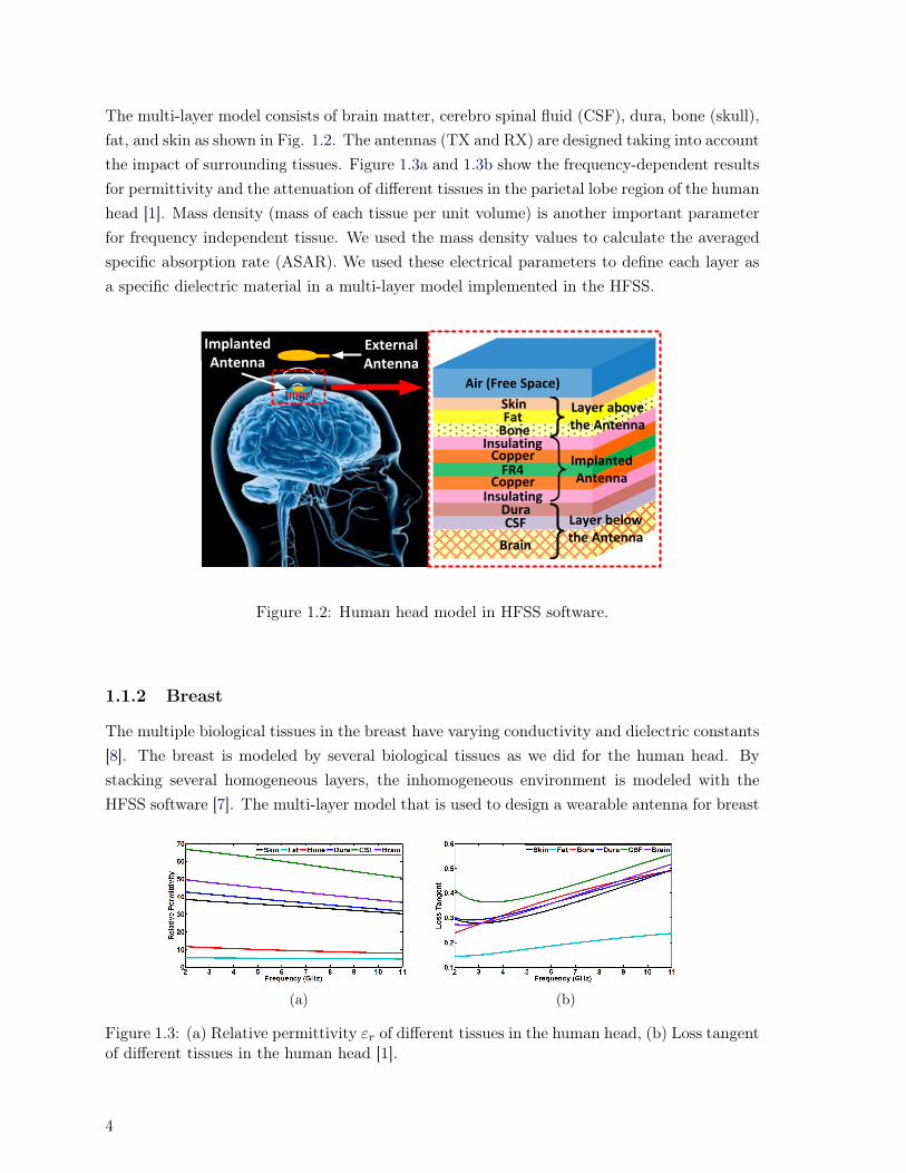
The multi-layer model consists of brain matter, cerebro spinal fluid (CSF), dura, bone (skull),fat, and skin as shown in Fig. 1.2. The antennas (TX and RX) are designed taking into accountthe impact of surrounding tissues. Figure 1.3a and 1.3b show the frequency-dependent resultsfor permittivity and the attenuation of different tissues in the parietal lobe region of the humanhead [1]. Mass density (mass of each tissue per unit volume) is another important parameterfor frequency independent tissue. We used the mass density values to calculate the averagedspecific absorption rate (ASAR). We used these electrical parameters to define each layer asa specific dielectric material in a multi-layer model implemented in the HFSS.
Implanted Antenna
External Antenna
SkinFat
Bone
DuraCSF
Brain
Insulating
Insulating
Copper
CopperFR4
Air (Free Space)
Layer above the Antenna
Layer below the Antenna
Implanted Antenna
Figure 1.2: Human head model in HFSS software.
1.1.2 Breast
The multiple biological tissues in the breast have varying conductivity and dielectric constants[8]. The breast is modeled by several biological tissues as we did for the human head. Bystacking several homogeneous layers, the inhomogeneous environment is modeled with theHFSS software [7]. The multi-layer model that is used to design a wearable antenna for breast
(a) (b)
Figure 1.3: (a) Relative permittivity εr of different tissues in the human head, (b) Loss tangentof different tissues in the human head [1].
4

cancer detection applications includes skin, fat, gland, and muscle, and is shown in Fig. 1.4 [8].The frequency dependent relative permittivity and loss tangent are presented in [1] for theentire 2-4 GHz band as shown in Fig. 1.5. The mass density, i.e., the mass of each tissue pervolume unit, is reported in [8] for different breast tissues.
Z
Y
X
Skin Fat
Muscle
Gland
0 45 90 (mm)
Figure 1.4: Human breast model in HFSS software.
1.2 Classification of Implantable and Wearable Antenna
The implantable UWB antenna is subject to specific requirements that render its design diffi-cult: 1) it is restricted to small dimensions, and 2) it must be bio-compatible [4–6]. Antennasize should be on the order of that of the implantable chip [3].
(a) (b)
Figure 1.5: (a) Relative permittivity εr of different tissues in the human breast, (b) Losstangent of different tissues in the human breast [1].
5
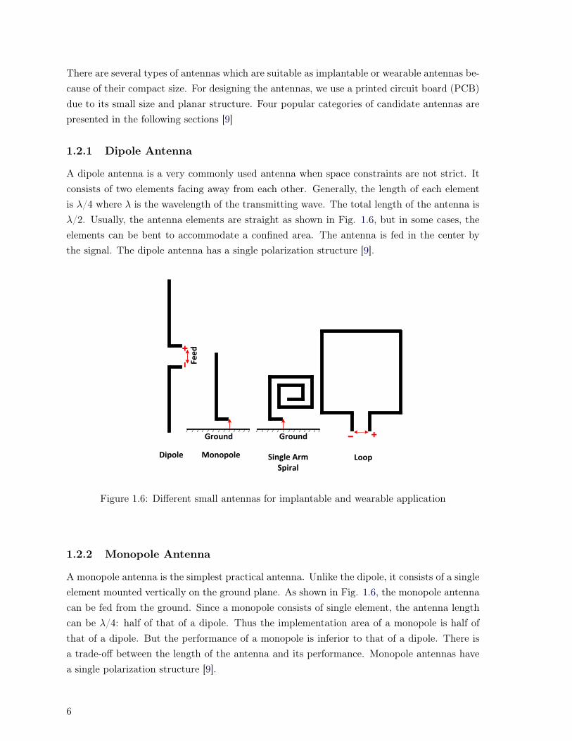
There are several types of antennas which are suitable as implantable or wearable antennas be-cause of their compact size. For designing the antennas, we use a printed circuit board (PCB)due to its small size and planar structure. Four popular categories of candidate antennas arepresented in the following sections [9]
1.2.1 Dipole Antenna
A dipole antenna is a very commonly used antenna when space constraints are not strict. Itconsists of two elements facing away from each other. Generally, the length of each elementis λ/4 where λ is the wavelength of the transmitting wave. The total length of the antenna isλ/2. Usually, the antenna elements are straight as shown in Fig. 1.6, but in some cases, theelements can be bent to accommodate a confined area. The antenna is fed in the center bythe signal. The dipole antenna has a single polarization structure [9].
Ground
Fee
d
Ground
Dipole Monopole Single Arm Spiral
Loop
Figure 1.6: Different small antennas for implantable and wearable application
1.2.2 Monopole Antenna
A monopole antenna is the simplest practical antenna. Unlike the dipole, it consists of a singleelement mounted vertically on the ground plane. As shown in Fig. 1.6, the monopole antennacan be fed from the ground. Since a monopole consists of single element, the antenna lengthcan be λ/4: half of that of a dipole. Thus the implementation area of a monopole is half ofthat of a dipole. But the performance of a monopole is inferior to that of a dipole. There isa trade-off between the length of the antenna and its performance. Monopole antennas havea single polarization structure [9].
6
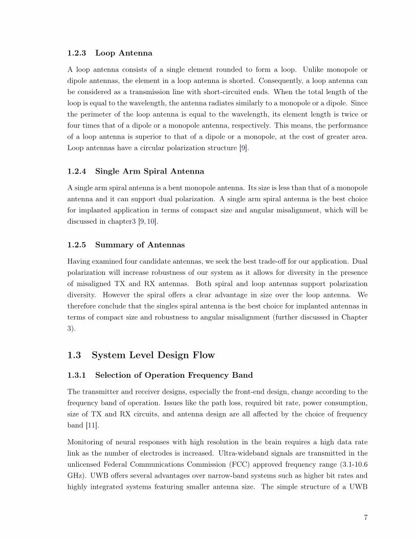
1.2.3 Loop Antenna
A loop antenna consists of a single element rounded to form a loop. Unlike monopole ordipole antennas, the element in a loop antenna is shorted. Consequently, a loop antenna canbe considered as a transmission line with short-circuited ends. When the total length of theloop is equal to the wavelength, the antenna radiates similarly to a monopole or a dipole. Sincethe perimeter of the loop antenna is equal to the wavelength, its element length is twice orfour times that of a dipole or a monopole antenna, respectively. This means, the performanceof a loop antenna is superior to that of a dipole or a monopole, at the cost of greater area.Loop antennas have a circular polarization structure [9].
1.2.4 Single Arm Spiral Antenna
A single arm spiral antenna is a bent monopole antenna. Its size is less than that of a monopoleantenna and it can support dual polarization. A single arm spiral antenna is the best choicefor implanted application in terms of compact size and angular misalignment, which will bediscussed in chapter3 [9, 10].
1.2.5 Summary of Antennas
Having examined four candidate antennas, we seek the best trade-off for our application. Dualpolarization will increase robustness of our system as it allows for diversity in the presenceof misaligned TX and RX antennas. Both spiral and loop antennas support polarizationdiversity. However the spiral offers a clear advantage in size over the loop antenna. Wetherefore conclude that the singles spiral antenna is the best choice for implanted antennas interms of compact size and robustness to angular misalignment (further discussed in Chapter3).
1.3 System Level Design Flow
1.3.1 Selection of Operation Frequency Band
The transmitter and receiver designs, especially the front-end design, change according to thefrequency band of operation. Issues like the path loss, required bit rate, power consumption,size of TX and RX circuits, and antenna design are all affected by the choice of frequencyband [11].
Monitoring of neural responses with high resolution in the brain requires a high data ratelink as the number of electrodes is increased. Ultra-wideband signals are transmitted in theunlicensed Federal Communications Commission (FCC) approved frequency range (3.1-10.6GHz). UWB offers several advantages over narrow-band systems such as higher bit rates andhighly integrated systems featuring smaller antenna size. The simple structure of a UWB
7

transmitter leads to low power consumption. The disadvantage of using the UWB band asopposed to a lower frequency band is higher loss [2, 3].
1.3.2 Consideration of Propagation Channel Model
In our project, the propagation channel model must include several tissues and two antennas(one implanted and one wearable antenna), as they are in very close proximity (in the nearfield relative to one another). The close proximity of transmitter and receiver antennas makesit impossible to treat transmission loss as independent of the antenna design (as is typicallythe case). The channel cannot be investigated separately from the antennas, but encompassestransmitter and receiver antennas and all adjacent tissues. S21 is the electromagnetic wavecoupling coefficient between the transmitter and receiver antennas, and it is the frequencyresponse for this near field communications system. This parameter can be calculated bysimulation or can be measured experimentally.
1.3.3 Link Budget Estimation
The link budget analysis helps to determine the feasibility of the communication system. Alink budget calculation is also an excellent means to understand the various factors whichmust be traded off to realize a given cost and level of reliability for a communication link.
Link budget estimation is the summation of gain and loss in the transmitter and receiversystem. From the link budget, we can find the receiver sensitivity and minimal signal tonoise ratio SNR needed for an acceptable bit error rate (BER) performance. The link budgetinvolves rough estimation of the following factors [11]:
- Receiver noise level
This parameter quantifies the extent to which the received signal is corrupted with noise.This parameter can be measured by a spectrum analyzer or a real time oscilloscope.
- Received signal power
This captures system losses for a reference transmission power, and can be measuredby a spectrum analyzer or a real time oscilloscope.
- Receiver sensitivity
BER performance varies with modulation and demodulation schemes. We investigateboth coherent and non-coherent detection, and determine the minimum receiver sensi-tivity required for acceptable BER performance for each method.
- Link margin
This parameterizes system robustness to unanticipated impairments.
8
The receiver sensitivity is calculated by the following equation
RXSensitivity(dBm) + LinkMargin(dB) = TXPower(dBm) + PathLoss(dB) (1.1)
1.3.4 Modulation and Demodulation Scheme Design
Complexity and power consumption can be traded-off when choosing between coherent andincoherent architectures. Coherent detection requires more complex circuitry which results inhigher power consumption; incoherent detection is less complex, which results in lower powerconsumption, but worse BER performance. In this thesis we work with On-off keying (OOK),differential phase shift keying (DPSK), and binary phase shift keying (BPSK) modulations.The primary purpose of this is optimization of the transmitted pulse and investigation of BERperformance of BPSK (coherent), DPSK (incoherent) and OOK (incoherent) modulations [11].
1.3.5 Circuit Level Design
Although circuit level design forms the last step in the design flow, it is one of the mostimportant tasks in the realization of a communication system. The architectures are differentfor different modulation schemes, however some components are common in most architectures.Components such as a pulse generator at the transmitter, and receiver front-end parts such asLNA and mixer are common to any architecture and play a crucial role in overall performance.In this thesis we investigate circuit level design of the transmitter for BPSK and OOK and anOOK receiver. Details are provided in Chapter 5.
1.4 Thesis Outline
In the previous sections of this chapter we presented the motivation for studying wireless UWBimplant-to-air communication systems for neural stimulating and recording applications. Wefocus on designing of implantable and wearable antennas. To design the antennas, we needto model the biological tissues in EM software like HFSS. These techniques are applicable toantennas for detection of breast tumors, and is a spin-off of our main research line. We alsoreviewed the critical parameters of system level design flow, which will be addressed in thisthesis.
In the following chapters, we present 1) the methodology of designing of implantable and wear-able antennas, 2) realistic channel modeling for wireless implant-to-air data communications,and 3) novel system level design for neural stimulating and recording systems.
Chapter 2 is devoted to realistic channel modeling for implant-to-air data communications.Our contributions are the following:
- UWB transmitter antenna design for two locations of the implant.
9

- Designing an UWB external receiver antenna.
- Calculating the maximum allowable transmitted power to respect ANSI and FCC rules.
- Calculating worst case receiver sensitivities.
In Chapter 3 we introduce a methodology for designing single- and dual-polarization antennason both rigid and flexible substrates for near-field communications of neural systems operatingover two frequency bands (ISM and UWB). Our contributions are:
- A methodology for designing flexible single- and dual-polarization antennas.
- Definition of a figure of merit for near-field communications of neural systems.
- Comparison of single- and dual-polarization antennas for this application.
In Chapter 4 a novel full-duplex data transceiver is proposed for neural stimulating and record-ing systems. The novel technique has better performance in terms of small size and verylow-power consumption. We modified the traditional use of separate up-link and down-linksubsystems, and propose a novel full-duplex data transceiver, with one dual band RF bidirec-tional data link. Our contributions are:
- Proposing a novel full-duplex data transceiver for neural systems.
- Experimental demonstration of achievable data rates of the proposed system.
Chapter 5 presents circuit level design and implementation of the UWB pulse shaper emulatedin experiments in chapter 4. Our contribution is:
- Circuit level implementation of a power efficient UWB pulse shaper on CMOS technol-ogy.
Chapter 6 presents a methodology for designing a flexible antenna array for radar-basedMicrowave Imaging (MI) for breast cancer diagnosis. This chapter presents a flexible 4×4monopole and single arm spiral UWB antenna array, in a format similar to that of a bra,operating in the 2-4 GHz spectrum that meets bandwidth requirements of breast-cancermicrowave-imaging. Our contributions are:
- Design of flexible 4×4 monopole and spiral antenna arrays on a 50 µm Kapton polyimide.
- Improved penetration of the propagated EM waves from the antennas into the breast byusing a reflector.
10

Finally, in Chapter 6, conclusions are drawn, and some of the possible future research plans,based on the material developed in this dissertation, are suggested.
11


Chapter 2
Biological Channel Modeling andImplantable UWB Antenna Design
Abstract
Results from this chapter were published in [J1]. Knowledge of channel behavior is re-quired to determine the maximum allowable power to 1) respect ANSI guidelines for avoid-ing tissue damage and 2) respect FCC guidelines on unlicensed transmissions. We utilize arealistic model of the biological channel to inform the design of antennas for the implantedtransmitter and the external receiver under these requirements. Antennas placement isexamined under two scenarios having contrasting power constraints. Performance of thesystem within the biological tissues is examined via simulation and experiment. Ourminiaturized antennas, 12 mm×12 mm, need worst case receiver sensitivities of -38 dBmand -30.5 dBm for the first and second scenarios, respectively. These sensitivities allow usto successfully detect signals transmitted through tissues in the 3.1-10.6 GHz UWB band.
2.1 Introduction
In this chapter the main contributions are:
- UWB transmitter antenna design for two locations of the implant.
- Designing an UWB external receiver antenna.
- Calculating the maximum allowable transmitted power to respect ANSI and FCC rules.
- Calculating worst case receiver sensitivities.
While UWB design for small size, low power consumption and high data rate has been widelyexamined, most antennas were designed for free space utilization [12, 13], not for use in hu-man tissue. Wireless implantable UWB transmitters specifically designed for data acquisition
13

systems implanted into the human head for neural recording have been examined in [3,10,14],however channel characteristics, average specific absorption rate (ASAR) and FCC guidelineson transmitted UWB power spectral density were not taken into account. The transmissionloss for the human head in the 100 MHz to 6 GHz band has been investigated in [15] for amm-size antenna without considering of the bandwidth of TX and RX antennas or the effectof biological tissues on system performance.
An antenna surrounded by biological tissues in its near-field acts as a new effective antennawith new propagation behavior and return loss different from the actual antenna. As a re-sult, an antenna designed for one part of the body (i.e., designed according to the dielectricproperties of that part of the body) might not operate as expected in another part of thebody. Planar microstrip UWB antennas, implanted in human tissues, have been designedand studied [5, 16–20], however not for human head tissues. Many of the implanted antennasproposed in the literature are designed for gastro applications [18–20]. In these applications,the antenna is moving in the body and experiences an environment with changing dielectricproperties, making the antenna optimization problematic. Furthermore, these antennas werefor the most part designed for a single layer of homogenous material [19]. So antennas usedfor gastro applications will not necessarily work well when implanted in the brain. Thesepapers [5, 16–20] focused on a methodology for designing a reliable wireless link for neuralrecording system using tissue modeling and designed antennas for this purpose. Head tissueis particularly sensitive, and ASAR requirements will tend to limit achievable data rate. Byexamining ASAR, we can accurately predict system performance (e.g., signal to noise ratio)for our antenna designs and target increased data rate.
In section 2.2, we present a model of biological tissues used for channel modeling, and discussthe implications of requiring a near-field analysis rather than far field for this application. Insection 2.3 we consider TX antenna design for two scenarios for the location of the implant. Wealso design a receiver antenna to be external to the body (one receiver antenna design coverseither location for the transmitter antenna). In section 2.4 we simulate the performance ofantennas designed in section 2.3, as well as the overall channel characteristics for the wirelesslink. In section 2.5 we fabricate and characterize three antennas (scenario 1 transmitterantenna (TX1), scenario 2 transmitter antenna (TX2), and a receiver antenna applicable toeither scenario (RX)). Characterization of the antenna with tissue present is accomplished byplacing the antennas in fresh brain and bone tissues of a sheep, as well as fat and skin froma chicken. Measured results are in good agreement with simulation. In section 2.6, potentialfor high data rates is concluded for neural recording which is based on our results. Finally,conclusions are drawn in section 2.7.
14
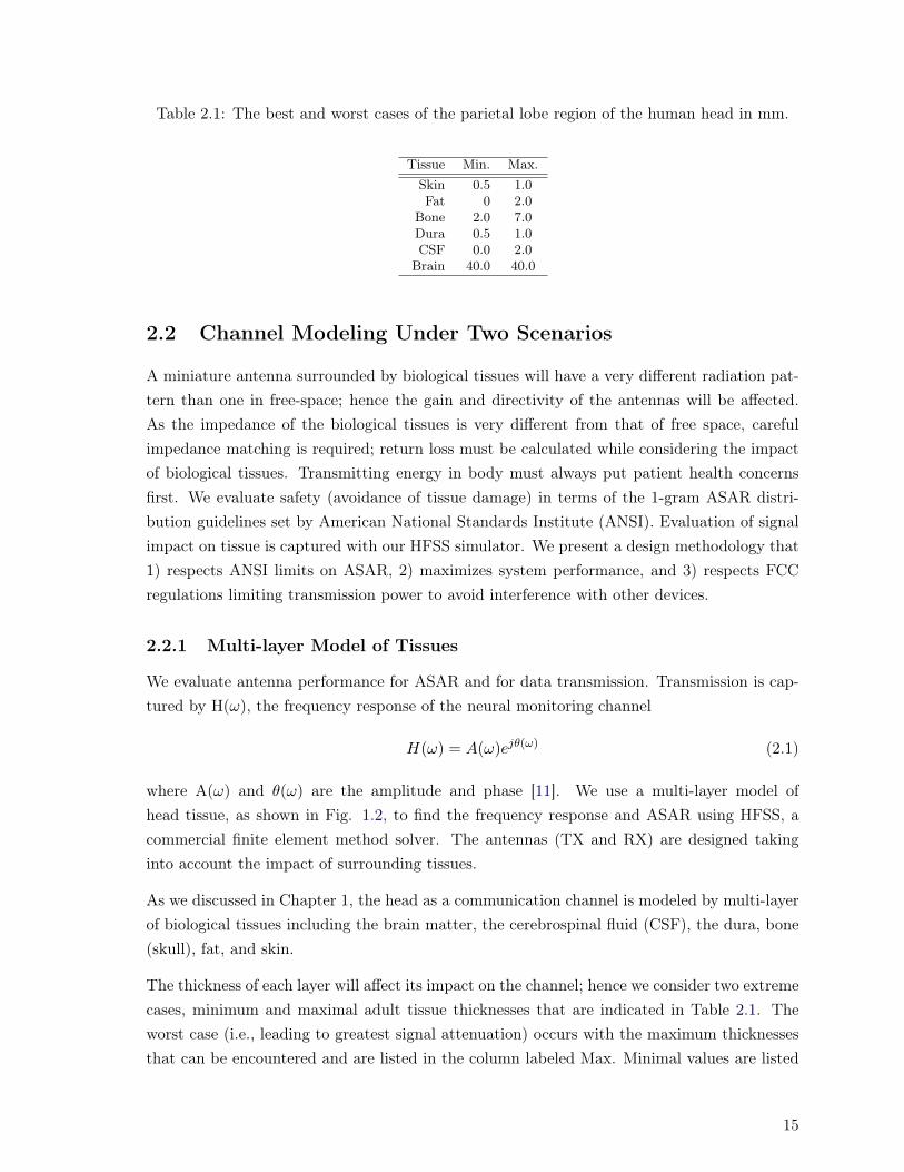
Table 2.1: The best and worst cases of the parietal lobe region of the human head in mm.
Tissue Min. Max.Skin 0.5 1.0Fat 0 2.0
Bone 2.0 7.0Dura 0.5 1.0CSF 0.0 2.0
Brain 40.0 40.0
2.2 Channel Modeling Under Two Scenarios
A miniature antenna surrounded by biological tissues will have a very different radiation pat-tern than one in free-space; hence the gain and directivity of the antennas will be affected.As the impedance of the biological tissues is very different from that of free space, carefulimpedance matching is required; return loss must be calculated while considering the impactof biological tissues. Transmitting energy in body must always put patient health concernsfirst. We evaluate safety (avoidance of tissue damage) in terms of the 1-gram ASAR distri-bution guidelines set by American National Standards Institute (ANSI). Evaluation of signalimpact on tissue is captured with our HFSS simulator. We present a design methodology that1) respects ANSI limits on ASAR, 2) maximizes system performance, and 3) respects FCCregulations limiting transmission power to avoid interference with other devices.
2.2.1 Multi-layer Model of Tissues
We evaluate antenna performance for ASAR and for data transmission. Transmission is cap-tured by H(ω), the frequency response of the neural monitoring channel
H(ω) = A(ω)ejθ(ω) (2.1)
where A(ω) and θ(ω) are the amplitude and phase [11]. We use a multi-layer model ofhead tissue, as shown in Fig. 1.2, to find the frequency response and ASAR using HFSS, acommercial finite element method solver. The antennas (TX and RX) are designed takinginto account the impact of surrounding tissues.
As we discussed in Chapter 1, the head as a communication channel is modeled by multi-layerof biological tissues including the brain matter, the cerebrospinal fluid (CSF), the dura, bone(skull), fat, and skin.
The thickness of each layer will affect its impact on the channel; hence we consider two extremecases, minimum and maximal adult tissue thicknesses that are indicated in Table 2.1. Theworst case (i.e., leading to greatest signal attenuation) occurs with the maximum thicknessesthat can be encountered and are listed in the column labeled Max. Minimal values are listed
15
He
ad M
od
el
Fre
e S
pac
e
Z-Y Plane
Reactive/FresnelNear Field Border
100 mm
Optimal RX Location
TX
2.8
mm
14 mm
(a)
D
0 35 70(mm)
(b)
Figure 2.1: a) E-field intensity at 3 GHz in the multi-layer model, (b) E-field intensity beyondthe Z-Y plane.
in the column Min. As the system must function for all cases encountered, we design theantennas for the worst case. We examine their performance for both best and worst case [21].
16

2.2.2 Near-field Behavior
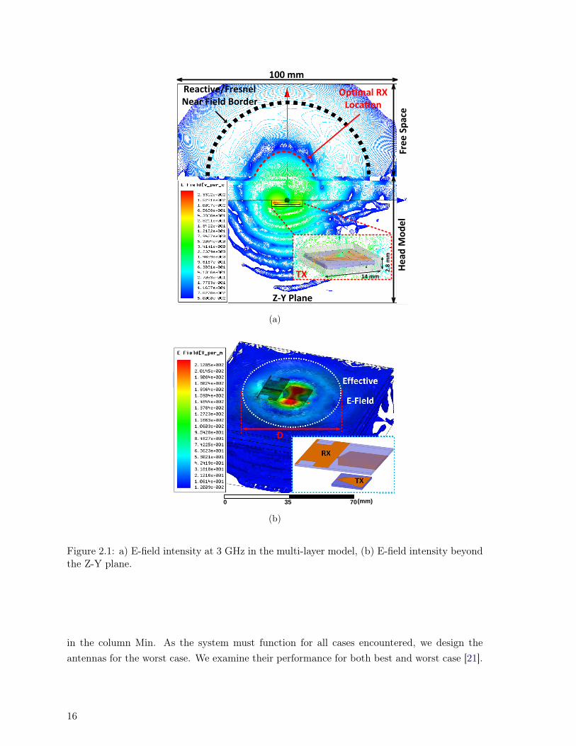
HFSS provides a three dimensional numerical solution for the electrical field intensity acrossall tissues. A planar cross section (Z-Y plane) of the intensity is plotted in Fig. 2.1a; a colorbar indicates that maximum intensity is in red, and minimal values in blue. The arrows on thefar right indicate sections corresponding to tissues in the head, and the section for free spacetransmission outside the head. The presumed location of the TX antenna is recognizable asthe position of maximum intensity (a fine box outlines antenna dimensions). This plot allowsus to visualize three important aspects of the transmission: 1) the intensity in surroundingtissue that will be used in ASAR calculations, 2) the border between near and far field effects,and 3) the optimal location for the RX antenna outside the head. We discuss in this sectionthe importance of near field effects.
The space surrounding an antenna is usually divided into three regions, 1) reactive near-field,2) radiating near-field (Fresnel), and 3) far-field (Fraunhofer) [22]. In the Fresnel region,the angular distribution of the electrical intensity is directive, but it varies with distance,whereas in the far-field, the intensity distribution of the radiated field is relatively constantwith distance. As shown in Fig. 2.1b most of the EM field is confined in the white dashedcircle that has a diameter of D = 67 mm. To calculate the border between different radiationregions in free space, we consider this dimension D of the effective antenna (combination ofthe implanted antenna and biological layers around it). The Fresnel region will be betweenreactive near field and far-field [22]. In Fig. 2.1a, the angular distribution of the electricalintensity begins to smooth out and forms lobes moving from near-field to far-field in the free-space section of Fig. 2.1a. The dashed curve (at a radius of 34 mm from the TX antenna)indicates an approximate border between the reactive near-field and Fresnel regions at 3 GHz.The red dashed curve in Fig. 2.1a (at a radius of 7 mm from the TX antenna) indicates theregion where RX placement will receive the strongest signal. Locating the RX antenna in thisregion will allow the RF signal to be small enough to avoid tissue damage, but strong enoughfor reliable wireless communications. Hence our system will work in the near-field rather thanfar-field for propagation. The close proximity of transmitter and receiver antennas (the mutualcoupling between the antennas) makes it impossible to treat transmission loss as independentof the antenna design (as is typically the case). The channel cannot be investigated separatelyfrom the antennas [23], but encompasses transmitter and receiver antennas and all adjacenttissues. S21 is the electromagnetic wave coupling coefficient between the transmitter andreceiver antennas and it is the frequency response for this near field communications system.
Antenna design should favor the broadside direction (red arrow in Fig. 2.1a). RF signalsbelow the TX antenna are not useful for communications, and indeed must be attenuated asmuch as possible to avoid tissue damage to highly sensitive brain cells. When the RX and TXantenna have reflection coefficients below -10 dB and the implanted TX antenna radiation isdirective to its broadside and the RX antenna is placed below the red border, we will achieve
17

the maximum coupling between antennas and reduce insertion loss of the channel. Finally,in Fig. 2.1b we plot a zoomed out image of the E-field intensity, including intensity beyondthe Z-Y plane. An inset shows the rough geometry of RX and TX antenna placement whose“shadow” is superimposed on the E-field plots. We see that within the white-dashed circlewe find the majority of the E-field power. HFSS simulations for S-parameter calculationsneed only cover this area to capture near field effects for communications performance and tocalculate ASAR, thus reducing simulation time.
The results in Fig. 2.1 are for Scenario 1 with the TX antenna located between bone anddura. For Scenario 2 the TX antenna would be located one layer higher between fat andbone. The tissue impact on antenna response will vary with position, hence antenna designand performance will differ across the two scenarios. But the general behavior of antennapropagation is the same, and we use the same design methodology for each scenario.
2.3 Antenna Design
The implantable UWB antenna is subject to specific requirements that render its designdifficult: 1) it is restricted to small dimensions, 2) it must be biocompatible, and 3) it needsto be electrically insulated from the body [4, 5, 16–20]. Antenna size should be on the orderof that of the implantable neural recording system [3,10,14]. Planar monopole antennas havesimple geometry, small size and wide bandwidth [12, 13]. We propose a monopole microstripantenna combined with a truncated ground plane covered by a biocompatible material toachieve wide bandwidth. Previous results show that employing an insulating layer increasesthe performance of the antennas [24–26].
The feed-line is a microstrip transmission line having 50-Ω impedance over the UWB band-width. The dimensions of the transmission line are a function of the electrical properties ofthe substrate as well as the environment (tissues and biocompatible material) surrounding thesubstrate. In [25, 26] we examined various biocompatible materials and settled on an Al2O3
superstrate with a thickness of 1 mm and relative permittivity 9.2 to yield the best compromisefor small size.
As we are designing a single polarization antenna, current induced on the antenna shouldfollow a single axis of propagation. A rectangular propagator yields the highest linearity incurrent. As the rectangular propagator is much wider than the transmission line, the returnloss will tend to be narrowband. We therefore adopt a taper geometry to couple the propagatorto the transmission line at the widest bandwidth [9]. Simulations show that modifying therectangular ground pad to adopt a staircase shape (truncated ground) provides better returnloss. By optimizing the width and length of the staircase, we optimize return loss. In HFSS wemodify antenna dimensions and gauge the impact of surrounding biological tissues using thefinite element method. We vary the length of the microstrip transmission line, the length of
18
a transversal, symmetric strip to the transmission line, and the size of the ground plane, andcalculate S11 and directivity at broadside for the entire UWB band. This numerical methodis repeated for TX1 (under skull, i.e., scenario 1), and TX2 (above skull and under skin andfat, i.e., scenario 2) until optimal dimensions are found. The next section describes antennaperformance that was optimized. The RX antenna outside the head is less constrained in sizeand our design constraints can be relaxed. For the RX antenna we adopt the same geometryas TX antennas, but without insulating layers. We optimize S11, but not directivity. Optimaldimensions of the antennas are reported in [26]. We fabricated these designs, and presentresults in section 2.5.
2.4 Simulated Performance
The performance of our three antenna designs is examined via HFSS simulation. The anten-nas were designed for the worst case (maximal signal attenuation) tissue thicknesses. Theperformance of these designs is examined when implanted in the worst and best cases.
2.4.1 Radiation and Return Loss
Figure 2.2a shows simulated directivity and gain as a function of frequency for TX1 and TX2for implantation in a worst case and a best case head geometry. For all scenarios, the air gapbetween the receiver antenna and the skin was set to 2 mm. Greater frequency resolution wassimulated as compared to results reported in [26]. In all cases directivity is above 0 dB, i.e.,the antennas are directive at broadside. Because the loss in biological tissues increases withfrequency, the gain of the antenna decreases roughly with frequency for implanted antennas(Fig. 2.2b). The radiation patterns of implanted antennas are directional due to the presenceof the dura, the CSF and the brain (because of their high absorption and high permittivity),as can be seen in Fig. 2.1a.
Simulation results for reflection coefficient (S11) are shown in Fig. 2.3a and 2.3b for the worstand best cases. The reflection coefficient is smaller than -10 dB within the UWB frequencyrange from 3.1 GHz to 10.6 GHz for each antenna. A properly designed pair of antennasfor short-range UWB communications has a TX antenna where 1) S11 is less than -10 dBand 2) directivity is more than 0 dB at the broadside. For the RX antenna, S11 must bebelow -10 dB when located where the TX antenna has highest radiation intensity [6]. Thesimulation S21 (the channel frequency response) results for both scenarios are plotted in Fig.2.4a (magnitude) and 2.4b (phase). In general, it shows that channel insertion loss increaseswith tissue thickness (the worst case having thicker tissues than the best case) and frequency.At higher frequencies, the loss tangent of tissues increases, which causes more loss whenelectromagnetic waves propagate though the tissues. As absorption in tissues increases withfrequency, system performance will increase when exploiting lower frequencies. From Fig.
19

2.4b, the channel phase is almost linear. When the channel frequency response has non-linearphase, signal distortion can result.
The group delay provides a measure of required guard time to avoid inter-symbol interference(ISI) due to signal distortion which it is defined:
τ(ω) = −dθ(ω)
dω(2.2)
The computed group delay for this channel is shown in Fig. 2.4c. The maximum group delaysare 130 ps and 160 ps for the worst case of scenario 1 and 2 respectively, and confined tofrequencies around 7.8 GHz. Discrete multi-tones could be used to avoid data transmission inthis frequency band. Pulse shaping could be used to place more power between 3-7 GHz. Pulseshaping could alternatively be used to create short UWB pulses, leaving pulses separated bymore than the worst case maximal group delay [27, 28]. In conclusion, at a bit-rate of 430Mbps the effect of ISI is negligible. Therefore, the only constraining parameter to achieve thisbit-rate (with a certain BER performance) is the transmitted power which translates to thereceived signal-to-noise ratio (SNR). In section 2.6, we discuss how our link can push datarate to our targeted 430 Mbps data rate which is enough to support 512 channels.
2.4.2 Federal Communication Committee (FCC)
UWB transmissions are limited by regulation. In the far field propagation of implanted an-tenna, we have a limitation on maximum transmitted power. The maximum power of thetransmitter plus maximum antenna gain (Pt+Gt) must be below 41.3 dBm/MHz. We willsee that this constraint is greater than that imposed by limiting tissue damage (found in thenext section). UWB bandwidth is around 7 GHz, thus the Pt+Gt allowed is [29]:
Pt +Gt = −41.3[dBm/MHz] + 10 × log10(7000) = .5mW (2.3)
The best case for the first scenario has a maximum gain of around -8.8 dB at 5.2 GHz. Thebest case for the second scenario has a maximum gain of around -6.3 dB at 5.8 GHz. Thereforethe maximum Pt for the first scenario is 3.9 mW (5.96 dBm), and 2.2 mW (3.46 dBm) forthe second scenario. In essence, the best case channel sees less signal attenuation, leading togreater restrictions to reduce potential interference.
2.4.3 Specific Absorption Rate (SAR)
ASAR (Average Specific Absorption Rate) is a critical parameter for assessing the tissuesafety of our transmissions. The peak 1-g ASAR distribution (maximum ASAR in everytissue) versus frequency is simulated with HFSS for both scenarios using only the worst caseparameter set. Note that worst case for signal attenuation is also worst case for ASAR asgreater tissue thickness has electromagnetic waves encountering more tissue. The averagetransmitted power at the excited port of the antenna in HFSS must be below 4.5 mW in order
20

(a) (b)
Figure 2.2: Simulated parameters for implanted antennas (a) directivty at broadside direction(b) gain at broadside direction.
(a) (b)
Figure 2.3: Simulated S11 for the antennas (a) the worst case (b) the best case.
to have an average absorption-rate of less than 1.6 W/kg (ANSI limitation [30]) in all tissuesin the UWB frequency range. This average transmitted power is equal in both scenarios;transmitting more power results in tissue damage.
This power is smaller than the 8 mW power level calculated in [6] for the biomedical frequencyband of 402–405 MHz to satisfy the ANSI SAR limitation. This is understandable as headtissue has significantly more loss in the UWB band than the 402–405 MHz band. Figure 2.5shows the ASAR for each tissue. In the first scenario, most power is absorbed by the skull(bone). For the second scenario, the skin has highest ASAR.
2.4.4 System Performance
For both antenna placement scenarios, the ANSI restrictions (4.5 mW) are less restrictivethan those imposed by the FCC (3.9 and 2.2 mW) for maximum power, so maximum poweris set by the FCC criteria. In practice, both constraints are higher than easily achievablesignal powers from implantable devices without amplification. The sensitivity of the receiveris obtained from (1.1). For a link margin of 6 dB, the worst case sensitivities of the receiverfor both the first and the second scenarios with worst transmission losses of -38 dB and -28dB at 10.6 GHz are around -38 dBm and -30.5 dBm, respectively. As can be seen in Fig. 2.4a,operation at lower frequency enables better receiver sensitivity, and better detection, becausethere is lower transmission loss.
21

(a) (b)
(c)
Figure 2.4: Simulated parameters for the antennas for two scenarios and best case and worstcase (a) amplitude of the channel, (b) phase of the channel, and (c) group delay of the channel.
(a) (b)
Figure 2.5: Simulated ASAR for different tissues (a) position under skull (b) above skull.
2.5 Fabrication and Measured Performance
In order to verify our simulation procedure in a realistic environment, we fabricated 12 mm ×12 mm monopole antennas on a FR-4 PCB board with a thickness of 0.8 mm and a dielectricconstant of 4.4. A 50-Ohm subminiature A (SMA) connector was used to connect the feedingstrip; its outer side was grounded to the ground plane. A 27 mm × 30 mm monopole receiverantenna was fabricated as well (RX). Photos of antennas are provided in Figures 2.6a, 2.6b,and 2.6c. As seen in Fig. 2.6d, implanted antennas are assumed to couple to a neuralrecording chip via a wire. To mimic implantation, we found animal tissues with thicknessesfalling between the worst case and best case values given in Table 2.1. It was not possibleto find tissues with exactly the best or worst case thicknesses. In this section we presentmeasurements and compare them to simulation results found with the thicknesses used in
22

tissues for the experimental measurements.
2.5.1 Network Analyzer Measurements
As reflection coefficient is a function of surrounding tissues, measurements were made in exvivo using fresh brain and bone tissues of a sheep, as well as fat and skin from a chicken. Theair-gap between the larger, external antenna and the skin was set to 2 mm in both simulationand measurements. For scenario 1, the antenna was placed underneath the skull, on top ofthe brain and the bone, and the skin and fat were put back in place to cover the antenna. Forscenario 2, the antenna was placed on top of the skull, underneath the fat and skin. Actualtissue thicknesses used in the measurement are 0.5, 1, 4, 0.5, 0.5 and 30 mm for skin, fat,bone, CSF, dura and brain, respectively.
In simulations, the relative permittivity and loss tangent of human tissue (not animal) wereused, with the actual thicknesses of the animal tissue present in experiments. S11 and S21 ofthe antennas were measured using an HP-8722ES network analyzer over a 8-GHz bandwidth,from 3 to 11 GHz. Figure 2.7 shows the experimental setup for S-parameter measurements forboth scenarios. Figure 2.8 compares the simulated and measured S11 (reflection coefficient)for all three fabricated antennas. Results show good impedance matching across a bandwidthof 3–10.6 GHz (S11 below 10 dB across the UWB band).
Although there is a slight difference between simulation and experimental results, they stillmatch (within 3 dB). Figure 2.9a and 2.9b compare simulation and measurement results forS21 (both amplitude and phase). Figure 2.9c shows the comparison between the simulatedand measured group delay. The electrical parameters of head tissues of most animals (ex-cept for some animal tissues like porcine skull) closely match those of humans [31]. However,these parameters do not exactly match, and slight differences between measured and simu-lated results arise. The differences can be attributed to: 1) inevitable deviations of electricalparameters of the test setup from those of the simulated model due to tissue age, temperature,the time passed since its death, etc. [32–34], 2) parasitic effects caused by soldering the SMAconnector to the PCB and the PCB fabrication errors, 3) uncertainty in the reported electricalparameters in the literature [35], and 4) presence of a small error in HFSS simulations due toconvergence. Taking into account all these factors, we find the deviations between simulationsand measurements acceptable.
2.5.2 Anechoic Chamber Measurements
Measurements were performed in an electromagnetic anechoic chamber with biological tissuespresent (using appropriate antenna geometry for each scenario). The radiation pattern at 7GHz (center frequency) was measured and is presented, in the XZ and YZ planes for bothscenarios, in Fig. 2.10. Patterns at other frequencies showed similar behavior. The measuredpatterns are in good agreement with the simulated patterns. Clearly our modeling captures
23
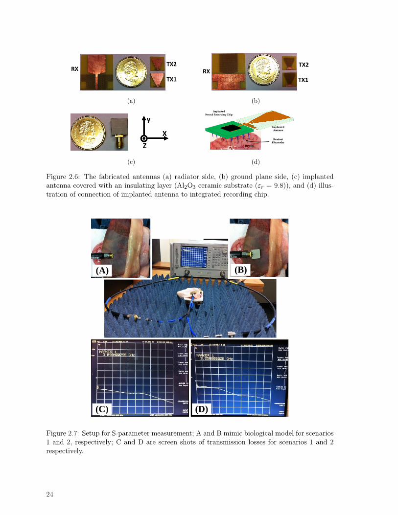
RX
TX1
TX2
(a)
RX
TX1
TX2
(b)
X
y
Z
(c)
Implanted
Antenna
Implanted
Neural Recording Chip
Readout
Electrodes
Brain
(d)
Figure 2.6: The fabricated antennas (a) radiator side, (b) ground plane side, (c) implantedantenna covered with an insulating layer (Al2O3 ceramic substrate (εr = 9.8)), and (d) illus-tration of connection of implanted antenna to integrated recording chip.
(A) (B)
(C) (D)
Figure 2.7: Setup for S-parameter measurement; A and B mimic biological model for scenarios1 and 2, respectively; C and D are screen shots of transmission losses for scenarios 1 and 2respectively.
24

(a) (b)
(c)
Figure 2.8: Comparison of simulated and measured return losses (a) the TX antenna forscenario1, (b) the TX antenna for scenario 2, and (c) the RX antenna.
(a) (b)
(c)
Figure 2.9: Comparison of simulated and measured (a) amplitude of the channel, (b) phaseof the channel, and (c) group delay characteristic of scenario 1 and scenario 2.
25

the influence of the human tissues on the antenna radiation patterns and it can be seenthat the effective antennas (combination of the biological tissues and the actual antenna) aredirectional. There is a slight distortion in the YZ plane, both in simulation and measurementresults. Despite this small distortion, the directivity peak of the implantable antennas isproperly located at broadside. The radiation pattern is perturbed by layers sliding on eachother when the antenna is rotated (by the motor that rotates the antenna when measuringthe radiation pattern). The radiation measurement of the antennas with biological tissues isa challenging task because of the difficulties of keeping the tissue layers in a fixed positionrelative to one another. As expected, the omnidirectional radiation of monopole antenna infree space has become directional due to the reflection and absorption by the tissues, such asthe dura, CSF and the brain.
By measuring the radiation patterns in E and H planes for each frequency, the directivity peakat broadside has been calculated using the following formula for different frequencies [22]:
D0 =4π
θ1 × θ2(2.4)
where
θ1= half-power beam-width in one plane.
θ2= half-power beam-width in a plane at right angles.
The maximum total gain vs. frequency in the broadside direction (θ = 0 and φ = 0) wasmeasured. From these results, the efficiency of the antenna (shown in Fig. 2.11) is calculatedby dividing the gain by the directivity. The antenna efficiency is much lower than the one forantennas designed for free-space applications, which are typically having efficiencies around70% [22], because the antenna is surrounded by the lossy biological environment. Figure 2.11shows that the antenna efficiency is greatest at lower frequencies where biological tissues havelower losses.
2.6 Potential for High Data Rate
In wireless communications, bit-error rate performance (BER) is limited by several factorsincluding inter-symbol interference (ISI), maximum allowable transmitted power, path-loss,etc. When ISI is not present, the only constraint on achieving higher bit-rates, for a specificbit -error rate (BER), is the signal-to-noise ratio [11]. Avoiding ISI requires wide bandwidth.For data-rates of several hundred kilobits per second, the 400-MHz and 2.4 GHz frequencybands can be used for implant-to-air communications [36,37].
However, for multichannel neural recording applications, the implanted transmitter needshigher data -rates. For this reason, we use UWB modulation techniques due to its widebandwidth. However, UWB signaling suffers from large attenuation for implant-to-air, which
26

leads to performance degradation. Therefore, characterizing the wireless channel is crucial.Several papers have studied different parts of the body as a wireless digital communication
Y-Z plane X-Z plane
Figure 2.10: Comparison of measured and simulated radiation pattern in the XZ plane andYZ plane for 7 GHz.
channel; however, none has studied the head [38–42]. Recently, two papers have investi-gated implant-to-air data communications [43,44]; one has a multi-pulse position modulation(MPPM) transmitter with a bit-rate of 1 Mbps [43] and another has a multi-band orthogonalfrequency division multiplexing (MB-OFDM) wireless system with a bit-rate of 80 Mbps [44].In those systems, the distance between the TX and RX antennas is around 120 mm in [43] and33 mm in [44], which results in greater loss than our system with 10 mm separation. Addition-ally, their transmitters respect the FCC limitations assuming free-space transmission. A TXantenna surrounded by biological tissues suffers significant signal attenuation before leavingthe body. Therefore, the implanted transmitters can transmit more power to compensate theloss, as long as tissue damage is avoided. In [44], the antenna was designed for free-space,which also results in much more channel insertion loss. The BER performance of implant-to-air UWB data communications for high-speed applications and the capacity of UWB wirelesschannel for neural recording systems have been discussed in [45,46].
2.7 Conclusion
Designing a reliable wireless data link in the presence of lossy tissues featuring frequency de-pendent dielectric properties is a challenging task. In this paper we introduced a methodologyfor designing a reliable wireless link for neural recording system using tissue modeling and de-
27

Figure 2.11: Measured radiation efficiency of the TX antennas at broadside (φ= 0, θ= 0) forscenario 1 and 2.
signing suitable antennas. For neural implants the antennas and the channel cannot be treatedseparately and needed to be simulated holistically. Simulations were carried out with HFSS,exploiting a layered model with different dielectric constants to capture the effect of surround-ing tissues. The maximum power allowed to be transmitted from the implanted antenna,taking into account the limits imposed by both the ANSI and the FCC, was deter-mined.Then receiver sensitivity was evaluated for two scenarios for transmitter antenna placement.
We reported simulation and experimental results for the two scenarios in a UWB wirelesslink for neural recording systems. Two UWB microstrip monopole antennas were designedand fabricated as the implantable transmitter antennas. A receive antenna was also designed,fabricated and tested. To verify our modeling and design procedure in a realistic environment,measurements were made in ex vivo using fresh brain and bone tissues of a sheep, as well as fatand skin from a chicken. Measurements matched simulation results, validating our approach.Our results are significant as the measured S21 between the receiver and the transmitterantenna allows derivation of the impulse response of the link, and hence computing of theachievable bit error rate of the communication link.
28

Chapter 3
Flexible, Polarization-Diverse UWBAntennas for Implantable NeuralRecording Systems
Abstract
In this chapter, published in [J2], we design single and dual-polarization antennas forwireless ultra-wideband neural recording and stimulating systems using an inhomoge-neous multi-layer model of the human head. Antennas made from flexible materials aremore easily adapted to implantation; we investigate both flexible and rigid materials andexamine performance trade-offs. The proposed antennas are designed to operate in a fre-quency range of 2–11 GHz (having S11 below -10 dB) covering both the 2.45 GHz (ISM)band and the 3.1–10.6 GHz UWB band. Measurements confirm simulation results show-ing flexible antennas have little performance degradation due to bending effects (in termsof impedance matching). Our miniaturized flexible antennas are 12 mm × 12 mm and 10mm × 9 mm for single- and dual-polarizations, respectively. Finally, a comparison is madeof four implantable antennas covering the 2-11 GHz range: 1) rigid, single polarization, 2)rigid, dual polarization, 3) flexible, single polarization and 4) flexible, dual polarization.In all cases a rigid antenna is used outside the body, with an appropriate polarization.Several advantages were confirmed for dual polarization antennas: 1) smaller size, 2) lowersensitivity to angular misalignments, and 3) higher fidelity.
3.1 Introduction
In this chapter the main contributions are:
- A methodology for designing flexible single- and dual-polarization antennas.
- Definition of a figure of merit for near-field communications of neural systems.
29

- Comparison of single- and dual-polarization antennas for this application.
As we mentioned in the previous chapter, the design of a miniature antenna surrounded bybiological tissues must take into account the effects of the tissues. Additionally the braintissues are physically sensitive in nature and flexible antennas, being more supple and moreeasily introduced into surrounding tissue, are highly suitable for use in implanted systems[47, 48]. Different wearable flexible antennas have been designed taking into account theeffects of biological tissues [49, 50]. In [47, 48], different types of flexible implanted antennaswere designed for the ISM and Med-Radio bands. To our knowledge, all reported implantedmicrostrip UWB antennas are rigid.
In our previous chapter, we designed a rigid single-polarization UWB microstrip antenna forneural recording systems [25, 26, 51]. Single-polarization antennas performance degrades inthe presence of angular misalignment between TX and RX antennas, which dual-polarizationantennas can correct [22,52–54]. Most narrowband flexible implanted antennas reported in theliterature are single-polarization [47, 48]. Implantable antenna with flexible substrates to beplaced inside the head must be biocompatible, and as thin and as soft as possible. In [55,56],a type of Kapton polyimide substrate showed these features.
In this chapter, we employed the same substrate as used in [55,56]. The copper (antenna) onthis substrate is covered by an identical layer of polyimide as is the superstrate. In section 3.2,we present the simulation setup for designing the antenna and identify the important criteriain designing the wireless link. In section 3.3 we describe the antenna design methodology.Section 3.4 presents simulation and measurement results. Performances of different antennaswere measured in realistic conditions by placing the antennas in fresh brain and bone tissuesof a sheep, as well as fat and skin from a chicken. Reported simulation results closely matchour measurements. Section 3.5 compares the flexible and rigid, single- and dual-polarizationantennas in terms of 1) average specific absorption rate (ASAR), 2) power efficiency, 3) fidelity,and 4) a figure-of-merit (FoM) defined in section 3.5. Finally, conclusions are drawn in sectionsection 3.6.
3.2 Modelling and Methodology
As we discussed in previous chapters, the multi-layer model [21] used to design the antennasincludes brain matter, cerebro-spinal fluid (CSF), Dura, bone (skull), fat, and skin, as shown inFig. 1.2. Antenna design for implanted medical devices should favor the broadside directivity[25,26,51], as RF signals below the TX antenna are not useful for communications, and indeedmust be attenuated as much as possible to avoid tissue damage to highly sensitive brain cells.
As already mentioned, in order to achieve the maximum coupling between TX and RX anten-nas, 1) their reflection coefficients (S11) must be kept below -10 dB (in order to have acceptable
30

Optimal RX Location
TX
Near/Far Field Border
Z
Y
9 mm
10 mmZ-Y Plane
He
ad M
od
el
Fre
e S
pac
e
100 mm
SkinFat
Bone
Brain
DuraCSF
Figure 3.1: Propagation behavior of E field intensity around the implanted antenna in Z-Yplane (referenced to 1 W transmitted power by the antenna).
matching with a 50 ohm impedance), 2) the implanted TX antenna near-field radiation pat-tern must be directed towards its broadside, and 3) the RX antenna must be positioned atthe intensity peak of the radiated EM field (outside the biological tissue). Our first step isdesigning a 50 ohm transmission line connected to the antenna propagator, while taking intoaccount the effect of biological tissues. The next step is finding initial dimensions of the prop-agator to meet required specifications (i.e., S11 below -10 dB for both TX and RX antennasand near-field directive radiation towards the broadside of the TX antenna) at a single fre-quency. Next, the propagator dimensions are optimized to extend the antenna bandwidth toachieve the bandwidth of interest. Details of design are given in the next section. The reddashed curve in Fig. 3.1 indicates the region where the RX antenna will receive the strongestsignal. Placing the RX antenna in this region (near-field) allows to transmit an RF signalsmall enough to avoid tissue damage, but strong enough for reliable wireless communications.
3.3 Antenna Design
Planar monopole (single-polarization) antennas have the potential to meet the mentionedconstraints in the previous chapter for implanted biomedical systems [12,25,26,51]. However,angular misalignment between these antennas degrades the received signals heavily. In orderto alleviate this problem, dual-polarization TX and RX antennas can be used [22, 52–54].
31

Recently rigid single-arm spiral antennas have been used for capsule endoscopy, body areanetworks and implantable neural recording systems [10, 57, 58]. The antennas presented in[57,58] are narrowband and operate at frequencies lower than those of UWB communications.These antennas were also rigid. The rigid antenna in [10] was designed without considering thebiological tissue effects. In this study we designed four types of TX antennas, two implantedsingle-polarization antennas (flexible and rigid) and two dual-polarization antennas (flexibleand rigid). Two external single- and dual-polarization antennas were designed as RX antennas.
Our signal-polarization and dual-polarization antennas are realized as monopole microstripand single-arm spiral antennas, respectively and are covered with a biocompatible material(Kapton polyimide). For all antennas, the feed circuit is a coplanar waveguide transmission line(CPW) having 50-Ω impedance over the 2-11 GHz frequency range. We have chosen the CPWsince its integration into the system, i.e., wire-bonding to the implantable chip, is convenientand straightforward. Dimensions of the CPW transmission line are designed respecting theelectrical properties of its substrate as well as those of the surrounding biological tissues. Weuse 0.1 mm Kapton polyimide as the biocompatible substrate for the flexible antennas. Therigid antennas have an Al2O3 substrate with a thickness of 0.7 mm. The relative permittivityof Kapton polyimide and Al2O3 is 3.5 and 9.2 respectively. For both antennas, a superstratelayer identical to their substrate layers covers the metal antenna traces. This superstratelayer completely isolated the antenna from the biological tissues making the antennas fullybiocompatible. The RX antennas, located outside the head, are less constrained in size andflexibility, so the design process is less complicated. Our RX antennas are fabricated on a FR4substrate (relative permittivity 4.4). RX antennas have the same structure as TX antennas,however, since they do not need to be biocompatible, they do not have the superstrate layerand they are slightly larger.
3.3.1 Single-Polarization Antennas
We proposed a monopole antenna that was optimized for implanted biomedical applicationswith a rigid substrate in the previous Chapter. In this work, we revisited the design fromchapter 2, using the same methodology but incorporating a flexible substrate more suitablefor neural implantation. We modified the transmission line dimensions for the TX and RXantennas to accommodate the new substrate and/or superstrate that are appropriate.
3.3.2 Dual-Polarization Antennas
Single-polarization antennas suffer from angular misalignment [22,52–54], which can be over-come using dual-polarization antennas. We design two implanted dual-polarization flexibleand rigid TX antennas and one rigid dual-polarization external RX antenna.
As in the previous section, the first step of design is tuning the CPW transmission line tohave a 50-Ω impedance in the frequency range of interest. We incorporate a spiral propagator
32

Figure 3.2: Simulated axial ratio of the dual polarization flexible TX and rigid RX antennas.
structure that induces a current equally on the antenna in both the horizontal and the verticalaxes. The spiral structure of the propagator consists of several rectangle-shaped pieces ofcopper placed on the X and the Y axes with shared current.
To have equal radiated power in the X and Y directions, the total length of the rectanglesin each direction must be equal. We achieve an S11 below -10 dB in the frequency rangeof interest (2-11 GHz) by matching the spiral propagator to the 50-Ω transmission line. Toimprove S11 bandwidth (while keeping it below -10 dB), the width of each rectangle in thespiral propagator is tuned. We placed the rectangular shapes as close as possible to decreasethe antenna size.
During optimization of the antenna dimensions, the maximum near-field radiation intensity ischecked to assure it is directed towards the broadside over the desired frequency range. Figure3.3 shows the induced current on implanted (TX) and external (RX) antennas. The currentis distributed almost equally in the X and Y directions.
We examine the axial ratio, i.e., the ratio of orthogonal components of an E-field. To calculatethe axial ratio (Ex/Ey), a single polarization antenna is needed to capture S21 in the Xdirection (representative of Ex) and S21 in the Y direction (representative of Ey) of the antennaof interest. For the implanted flexible TX dual polarization antenna, the external RX singlepolarization antenna is used. To calculate the axial ratio of the RX dual polarization antenna,the implanted flexible TX single polarization antenna is used.
The simulated axial ratio is shown in Fig. 3.2. Every attempt was made to orient antennas formaximum coupling and least insertion loss in the simulation. Because the implanted antennais roughly three times smaller than the external antenna and the TX and RX antennas arevery close to each other, Fig. 3.2 is our best approximation of the axial ratio.
33
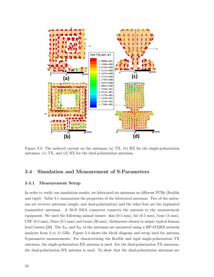
0 4 8 (mm)0 4.5 9(mm)
0 10 20 (mm) 0 15 30 (mm)
(a)
(b)
(c)
(d)
Figure 3.3: The induced current on the antennas (a) TX, (b) RX for the single-polarizationantennas, (c) TX, and (d) RX for the dual-polarization antennas.
3.4 Simulation and Measurement of S-Parameters
3.4.1 Measurement Setup
In order to verify our simulation results, we fabricated six antennas on different PCBs (flexibleand rigid). Table 3.1 summarizes the properties of the fabricated antennas. Two of the anten-nas are receiver antennas (single- and dual-polarization) and the other four are the implantedtransmitter antennas. A 50-Ω SMA connector connects the antenna to the measurementequipment. We used the following animal tissues: skin (0.5 mm), fat (0.5 mm), bone (3 mm),CSF (0.5 mm), Dura (0.5 mm) and brain (30 mm), thicknesses chosen to mimic typical humanhead tissues [28]. The S11 and S21 of the antennas are measured using a HP-8722ES networkanalyzer from 2 to 11 GHz. Figure 3.4 shows the block diagram and setup used for antennaS-parameter measurements. For characterizing the flexible and rigid single-polarization TXantennas, the single-polarization RX antenna is used. For the dual-polarization TX antennas,the dual-polarization RX antenna is used. To show that the dual-polarization antennas are
34
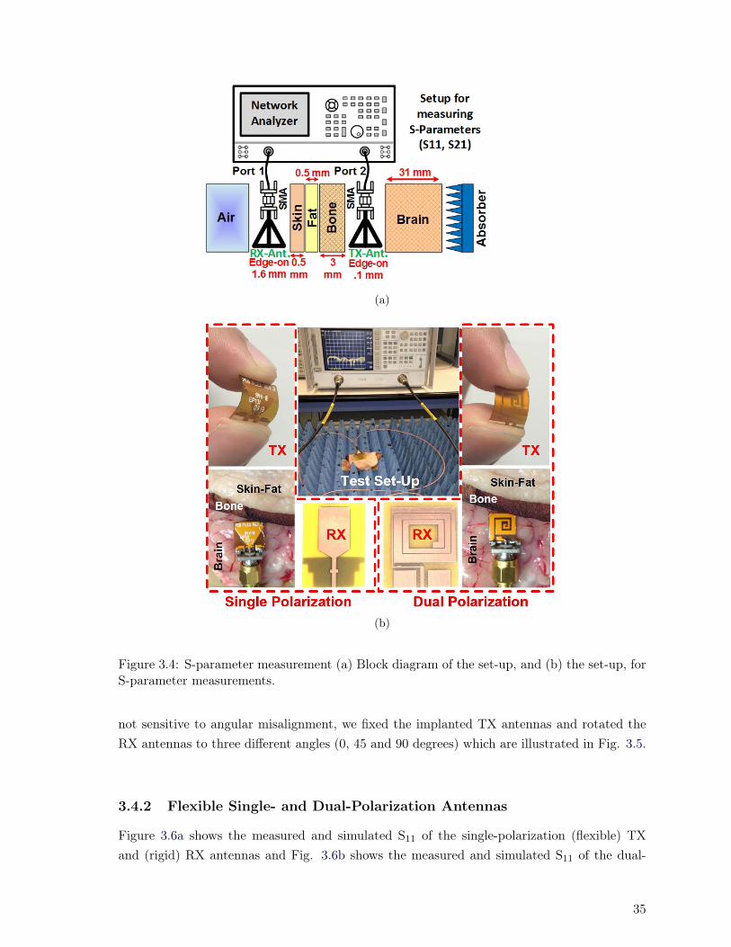
(a)
(b)
Figure 3.4: S-parameter measurement (a) Block diagram of the set-up, and (b) the set-up, forS-parameter measurements.
not sensitive to angular misalignment, we fixed the implanted TX antennas and rotated theRX antennas to three different angles (0, 45 and 90 degrees) which are illustrated in Fig. 3.5.
3.4.2 Flexible Single- and Dual-Polarization Antennas
Figure 3.6a shows the measured and simulated S11 of the single-polarization (flexible) TXand (rigid) RX antennas and Fig. 3.6b shows the measured and simulated S11 of the dual-
35
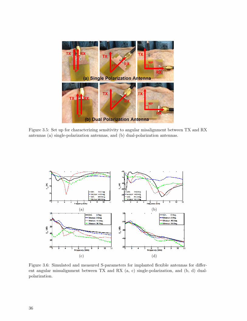
Figure 3.5: Set up for characterizing sensitivity to angular misalignment between TX and RXantennas (a) single-polarization antennas, and (b) dual-polarization antennas.
(a) (b)
(c) (d)
Figure 3.6: Simulated and measured S-parameters for implanted flexible antennas for differ-ent angular missalignment between TX and RX (a, c) single-polarization, and (b, d) dual-polarization.
36
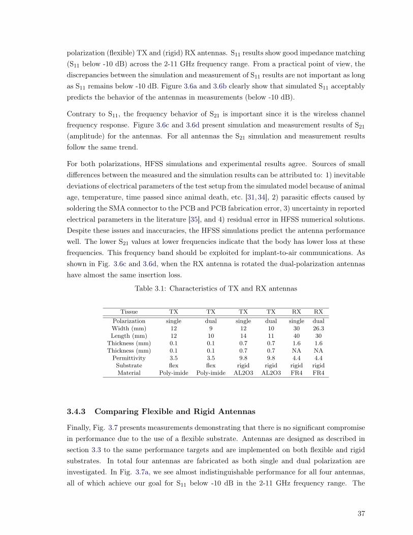
polarization (flexible) TX and (rigid) RX antennas. S11 results show good impedance matching(S11 below -10 dB) across the 2-11 GHz frequency range. From a practical point of view, thediscrepancies between the simulation and measurement of S11 results are not important as longas S11 remains below -10 dB. Figure 3.6a and 3.6b clearly show that simulated S11 acceptablypredicts the behavior of the antennas in measurements (below -10 dB).
Contrary to S11, the frequency behavior of S21 is important since it is the wireless channelfrequency response. Figure 3.6c and 3.6d present simulation and measurement results of S21(amplitude) for the antennas. For all antennas the S21 simulation and measurement resultsfollow the same trend.
For both polarizations, HFSS simulations and experimental results agree. Sources of smalldifferences between the measured and the simulation results can be attributed to: 1) inevitabledeviations of electrical parameters of the test setup from the simulated model because of animalage, temperature, time passed since animal death, etc. [31, 34], 2) parasitic effects caused bysoldering the SMA connector to the PCB and PCB fabrication error, 3) uncertainty in reportedelectrical parameters in the literature [35], and 4) residual error in HFSS numerical solutions.Despite these issues and inaccuracies, the HFSS simulations predict the antenna performancewell. The lower S21 values at lower frequencies indicate that the body has lower loss at thesefrequencies. This frequency band should be exploited for implant-to-air communications. Asshown in Fig. 3.6c and 3.6d, when the RX antenna is rotated the dual-polarization antennashave almost the same insertion loss.
Table 3.1: Characteristics of TX and RX antennas
Tissue TX TX TX TX RX RXPolarization single dual single dual single dualWidth (mm) 12 9 12 10 30 26.3Length (mm) 12 10 14 11 40 30
Thickness (mm) 0.1 0.1 0.7 0.7 1.6 1.6Thickness (mm) 0.1 0.1 0.7 0.7 NA NAPermittivity 3.5 3.5 9.8 9.8 4.4 4.4Substrate flex flex rigid rigid rigid rigidMaterial Poly-imide Poly-imide AL2O3 AL2O3 FR4 FR4
3.4.3 Comparing Flexible and Rigid Antennas
Finally, Fig. 3.7 presents measurements demonstrating that there is no significant compromisein performance due to the use of a flexible substrate. Antennas are designed as described insection 3.3 to the same performance targets and are implemented on both flexible and rigidsubstrates. In total four antennas are fabricated as both single and dual polarization areinvestigated. In Fig. 3.7a, we see almost indistinguishable performance for all four antennas,all of which achieve our goal for S11 below -10 dB in the 2-11 GHz frequency range. The
37

(a) (b)
Figure 3.7: Comparison of the measured results of the antennas (a) S21, and (b) group delay.
measured group delay in Fig. 3.7b shows that the flexible dual-polarization antenna exhibitsthe best performance of the four antennas, introducing little pulse distortion across the entireUWB frequency band. In conclusion, flexible and rigid antennas have similar efficiency, whilein our opinion, flexible antennas are likely to offer less risk of tissues damage.
3.5 Near-Field Characteristics of Antennas
In near-field communications, the close proximity of the transmitter and receiver antennasleads to high mutual coupling between the antennas. Transmission loss is therefore not inde-pendent of the antenna effects [25,26,51]. In this section, we discuss the efficiency of antennasfrom a near-field link viewpoint. We find the ASAR and the received power when a spe-cific signal is transmitted for each implanted antenna. Furthermore, we define fidelity and afigure-of-merit (FoM) for the near-field link.
3.5.1 Specific Absorption Rate (ASAR)
Average Specific Absorption Rate (ASAR) describes the electromagnetic energy that is ab-sorbed in biological tissues and is a critical parameter for assessing the tissue-safety of implant-to-air wireless communications. The peak 1-g ASAR spatial distribution versus frequency issimulated in HFSS for all four implanted antennas. The results are presented in Table 3.2.ANSI limitations for a maximum peak 1-g ASAR of 1.6 W/kg [30] translates into differentaverage radiated power for each antenna: 3.5 mW for single-polarization flexible and rigidimplanted antennas, 5.7 mW for flexible dual-polarization antennas, and 3.9 mW for rigiddual-polarization antennas. Sending more power can damage the biological tissues. Figure3.8 shows that most of the radiated power is absorbed by the skin for single-polarization andby the Dura for dual-polarization antennas.
3.5.2 Power Efficiency
Both ASAR limitations on tissue damage and FCC limitations on maximum transmitted powerlead to challenging reception of UWB signals [51]. The pulse selected for transmission will
38
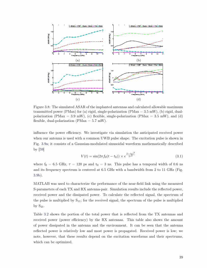
(a) (b)
(c) (d)
Figure 3.8: The simulated ASAR of the implanted antennas and calculated allowable maximumtransmitted power (PMax) for (a) rigid, single-polarization (PMax = 3.5 mW), (b) rigid, dual-polarization (PMax = 3.9 mW), (c) flexible, single-polarization (PMax = 3.5 mW), and (d)flexible, dual-polarization (PMax = 5.7 mW).
influence the power efficiency. We investigate via simulation the anticipated received powerwhen our antenna is used with a common UWB pulse shape. The excitation pulse is shown inFig. 3.9a; it consists of a Gaussian-modulated sinusoidal waveform mathematically describedby [59]
V (t) = sin(2πf0(t− t0)) × e(t−t0)
2
2τ2 (3.1)
where f0 = 6.5 GHz, τ = 120 ps and t0 = 3 ns. This pulse has a temporal width of 0.6 nsand its frequency spectrum is centered at 6.5 GHz with a bandwidth from 2 to 11 GHz (Fig.3.9b).
MATLAB was used to characterize the performance of the near-field link using the measuredS-parameters of each TX and RX antenna-pair. Simulation results include the reflected power,received power and the dissipated power. To calculate the reflected signal, the spectrum ofthe pulse is multiplied by S11; for the received signal, the spectrum of the pulse is multipliedby S21.
Table 3.2 shows the portion of the total power that is reflected from the TX antennas andreceived power (power efficiency) by the RX antennas. This table also shows the amountof power dissipated in the antenna and the environment. It can be seen that the antennareflected power is relatively low and most power is propagated. Received power is low; wenote, however, that these results depend on the excitation waveforms and their spectrums,which can be optimized.
39

(a) (b)
Figure 3.9: (a) Waveform of the Gaussian modulated sine wave described by (3.1), and (b) itsspectrum.
3.5.3 Fidelity Factor of the Near-field Links
System performance is optimized when the received waveform is a replicate of the transmittedwaveform with no distortion. Simple design goals for amplitude and group delay attemptto minimize the distortion. Unlike narrowband antennas, UWB antennas can significantlyalter transmitted pulses, due to considerably different behavior across the wide frequencyband [60,61]. The antenna fidelity factor (in the far-field) captures the similarity between theideal expected output waveform of an antenna and the actual radiated waveform. The antennais assumed to introduce one of three effects (replication, integration or derivation), which werefer to as the antenna effect, that is incidental to the design process. For a given pulse shape,the result of an ideal antenna effect acting on that pulse shape is different from the actualradiated waveform. The fidelity factor is defined as the maximum cross-correlation betweenthe ideal and the actual radiated waveforms when both waveforms are normalized by theirenergies [16,59–61]. Fidelity varies between zero and one, with one showing the minimum andzero showing the maximum distortion introduced by the antenna.
The impact of UWB transmit antenna geometry, material, current mode and transmitterimpedance interact to a combined effect that might introduces integration or derivation insteadof simple replication [60,61]. More importantly, the TX antenna can interact with other systemcomponents (exciting pulse shape, communication channel, and receive antenna geometry,material, etc.) to have an overall effect which we call the link effect. This behavior can beparticularly influenced by operation in the near-field. We define a fidelity factor for near-fieldapplications. Unlike the far-field definition of fidelity, our near-field definition considers theeffect of the TX antenna, the radiation medium (the biological tissues) and the receiver antennacharacteristics. Let r(t) be the received pulse for an ideal link effect (which we assume takesone of three forms of replication, integration or derivation) for a given excitation pulse shape.Let Sr(t) be the actual received waveform for that excitation pulse shape. The near-fieldfidelity is defined as the following assuming r(t) and Sr(t) have normalized energies
F = max
∫ +∞
−∞r(t) × Sr(t+ τ)dt (3.2)
We examined the four transmit antennas we designed (dual/single polarization, rigid/flexible
40

(a) (b)
(c) (d)
Figure 3.10: Distorted received pulse which is calculated based on the measured S21 forantennas with (a) flexible, dual-polarization, (b) flexible, single-polarization, (c) rigid, single-polarization, and (d) rigid dual-polarization.
substrate) and determined the link effect for each for the near-field biological channel. Asindicated in Table 3.2, we found the single polarization, flexible substrate antenna and thedual polarization, rigid substrate antennas formed a system that replicated the transmittedsignal without integration or derivation. The other two antennas formed a link whose overalleffect was integration. In Fig. 3.10 we plot r(t) (solid lines) and Sr(t) (dotted lines) for eachof the four transmit antennas. We derive Sr(t) by calculating the inverse Fourier transformof the multiplication of the pulse spectrum of (3.1) by the measured S21 of the antenna pairs.In two cases the link effect is to replicate the input transmit signal, whereas the other twointegrate the input transmit signal. The fidelity factors calculated from (3.2) are given in Table3.2, showing dual-polarization antennas perform better than single-polarization antennas. Insum, the dual-polarization antennas have three advantages in comparison with the single-polarization antennas: 1) smaller size, 2) lower sensitivity to angular misalignments, and 3)higher fidelity.
3.5.4 Figure of Merit (FoM)
To compare the designed antennas in near-field applications, we propose a figure of merit(FoM). Our FoM is based on parameters that play an important role in the performanceof the near-field wireless links: 1) Pe: power efficiency (%), 2) A: TX antenna area (m2)(RX antenna is much larger than TX antenna and changing its size does not change the linkperformance when it is close to a small antenna), 3) d: the distance between the RX and TXantennas which in this work is 4.0×10⁻³ m, 4) PMax: maximum allowable transmitted power
41

Table 3.2: Near-field characteristic of the TX antennas
Performance single dual single dualSubstrate flex flex rigid rigid
Reflected Power 2.4% 2% 2.6% 2.8%Power Efficiency .04% .05% .03% .11%Dissipated Power 97.56% 97.95% 97.37% 97.09%
Link Effect replication integration integration replicationLink Fidelity .81 .96 .84 .93
FoM 3.2 7.3 2.1 14.5PMax (mW) 3.5 5.7 3.5 3.9
RX sensitivity (dBm) -34.6 -31.5 -35.8 -29.7
(mW) (according to ANSI limitations), and 5) F: fidelity factor. The FoM is defined as
FoM =Pe × d× F × PMax
A(3.3)
In Table 3.2, FoM is calculated for the four designed links with different polarizations. Theresults show that the dual-polarization antennas have a higher FoM. As a result, this type ofantenna is the best candidate for neural recording application.
3.5.5 Bending Effect
Given the size of antennas and the natural curvature of the head, at most 10 degrees ofbending would be encountered in vivo. To stress our design, we examined impairments with 30degrees of bending of the implanted antenna. The S11 behavior of the flexible antennas underbending is characterized and shown in Fig. 3.11 (the antennas are bent 30° while still touchingthe biological tissues). The results show that the S11 remains below -10 dB irrespective ofbending. Power efficiency passed from .04% and .05% to .03% and .04% for single and dualpolarization under 30 degrees flexing, respectively. Fidelity went from 0.81 to 0.72 for singlepolarization, and 0.96 to 0.81 for dual polarization. Finally, ASAR considerations would leadto the maximum transmit power of 3.5 mW reduced to 1.3 mW for single polarization, and5.7 mW reduced to 1.5 mW for dual polarization. Bending would lead to some impairment,though parameters are still acceptable even in the extreme 30 degree case.
3.6 Conclusion
We presented a methodology for designing implanted single- and dual-polarization antennason a flexible substrate for neural recording systems operating over two frequency bands (ISMand UWB). We compared single and dual polarization antennas on both rigid and flexiblesubstrates. We found that no significant performance reduction was incurred in moving toflexible substrates that are better adapted to neurological implants. Several advantages were
42

A B C D
Figure 3.11: Comparison of measured S11 (A, C) for zero bending of the flexible TX antennasand (B, D) for 30 degree bending of the flexible TX antennas.
uncovered for dual polarization antennas: 1) smaller size, 2) lower sensitivity to angularmisalignments, and 3) higher fidelity.
In near-field implant-to-air biomedical applications, the TX and RX antennas and the biolog-ical tissues between them cannot be treated separately and need to be simulated holistically.All our simulations were carried out in HFSS by exploiting an inhomogeneous, multi-layermodel of biological tissues. To verify the validity of our model and the antenna design pro-cedure, ex vivo measurements were made using fresh brain and bone tissues of a sheep, andfat and skin from a chicken. Measurement and simulation results are in good agreement andvalidate the proposed antenna design methodology and biological tissue modeling. We in-vestigated the maximum allowable transmitted power with respect to ANSI limitations. Wealso simulated and measured the biological channel overall link effect on pulse transmissionand reception. Finally, in order to compare the designed antennas for near-field biologicalapplications, a figure of merit has been suggested.
43

Chapter 4
System Level Design of High-SpeedFull-Duplex Transceiver for NeuralRecording and Stimulating Systems
Abstract
Results from this chapter were presented in [J3]. We propose a wireless communicationsarchitecture for implanted systems that simultaneously stimulate neurons and record neu-ral responses. This architecture supports large numbers of electrodes (>500), providing100 Mb/s for the downlink of stimulation signals, and Gb/s for the uplink neural record-ings. We propose a transceiver architecture that shares one ultra-wideband antenna, astreamlined transceiver working at full-duplex on both bands, and a novel pulse shaperfor the Gb/s uplink supporting several modulation formats. We present an ex-vivo ex-perimental demonstration of the architecture using discrete components achieving Gb/suplink rates. Good bit error rate performance over a biological channel at 0.5, 1, and 2Gbps data rates for uplink telemetry (UWB) and 100 Mbps for downlink telemetry (2.45GHz band) was achieved.
4.1 Introduction
In this chapter the main contributions are:
- Proposing a novel full-duplex data transceiver for neural systems.
- Experimental demonstration of achievable data rates of the proposed system.
Simultaneous neural stimulating and recording systems require many electrodes interfaced,perhaps permanently, to the central and peripheral nervous systems. In wireless neural record-
45

ing applications, increasing the number of electrodes enhances understanding of the targetedpart of the brain. More electrodes lead to a requirement for higher speed links.
In neural stimulating and recording systems, as shown in Fig. 4.1, conventionally three sepa-rate links are required: one power inductive link and two separate communication subsystems(uplink and downlink) [10, 62, 63]. Inductive data subsystems are utilized when the requireddata rate is low, on the order of a few Mbps [10, 62, 63]. To achieve a higher data ratefor the uplink in a neural recording system, an ultra-wideband RF communication subsys-tem was utilized instead of the inductive approach; the inductive approach was kept for thedownlink [3, 10]. As the number of electrodes increases, the downlink needs wider bandwidth(and hence a higher RF frequency) to be able to support modulated (100 Mbps) datarates.Recently, we proposed 2.45 GHz industrial, scientific and medical (ISM) band as a forwardlink [64]. We will show in this paper that the 2.45 GHz downlink receiver can be operatedin full duplex with a high data rate ultra-wideband band (UWB) uplink transmitter. The
Figure 4.1: Brain-machine interface solutions: (a) conventional architecture with separateuplink transmitter and downlink receivers, and (b) the proposed full-duplex, dual-bandtransceiver.
most important features for the implanted circuit are small size and very low power consump-tion [3,3,14,65–67]. To achieve these goals we modify the traditional use of separate uplink anddownlink subsystems, and propose a novel full-duplex data transceiver, with one dual bandRF bidirectional data link. We avoid a power-hungry circulator by shaping the transmittedsignal to take advantage of the low noise amplifier (LNA) filtering feature at the implanteddownlink receiver. We shape the transmitted pulse to put most energy between 3.1-7 GHz.This also allows for good isolation from the 2.4 GHz achieving low crosstalk between uplinkand downlink. Because of very lossy behavior of head tissues at 7-10.6 GHz [51], this pulseshaping also enhances uplink power efficiency. This novel technique is the simplest possiblefull-duplex transceiver structure, employing a circuit that is power efficient and small in size,making it suitable for biomedical applications.
46
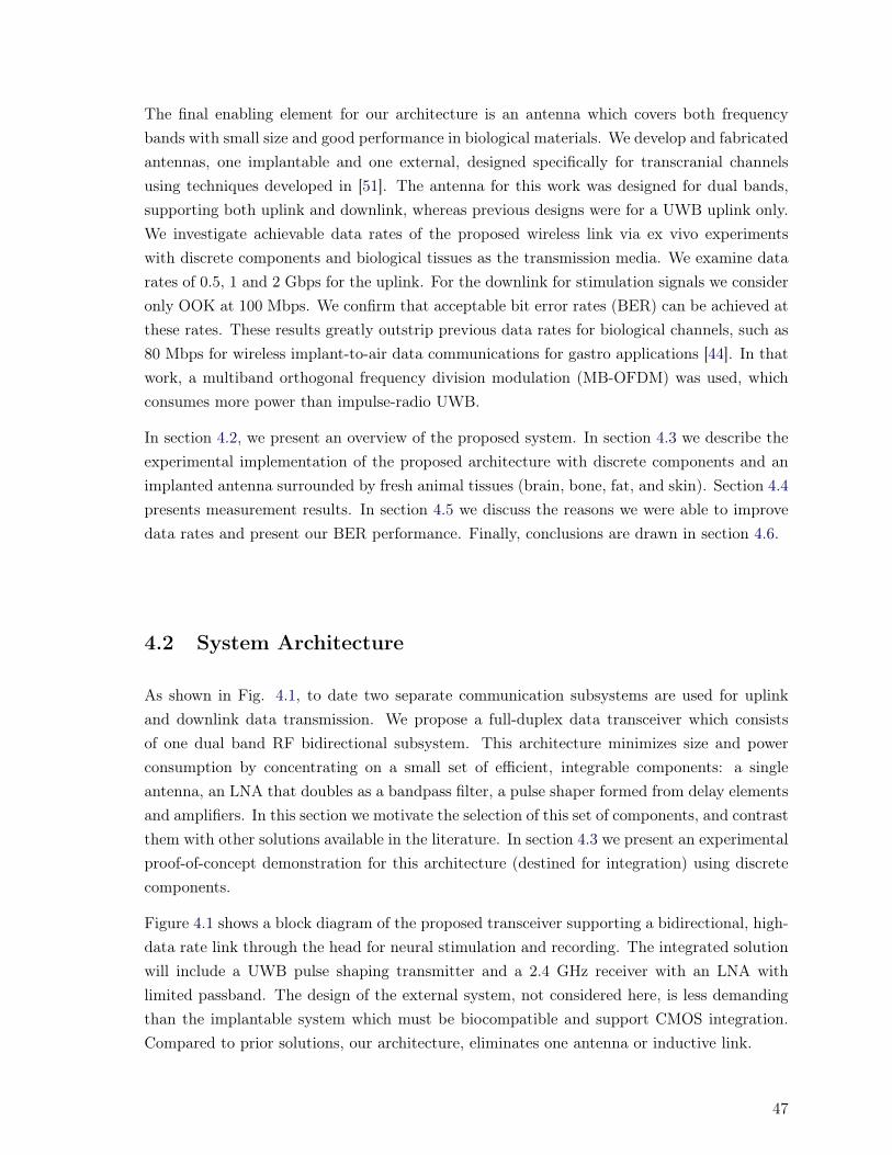
The final enabling element for our architecture is an antenna which covers both frequencybands with small size and good performance in biological materials. We develop and fabricatedantennas, one implantable and one external, designed specifically for transcranial channelsusing techniques developed in [51]. The antenna for this work was designed for dual bands,supporting both uplink and downlink, whereas previous designs were for a UWB uplink only.We investigate achievable data rates of the proposed wireless link via ex vivo experimentswith discrete components and biological tissues as the transmission media. We examine datarates of 0.5, 1 and 2 Gbps for the uplink. For the downlink for stimulation signals we consideronly OOK at 100 Mbps. We confirm that acceptable bit error rates (BER) can be achieved atthese rates. These results greatly outstrip previous data rates for biological channels, such as80 Mbps for wireless implant-to-air data communications for gastro applications [44]. In thatwork, a multiband orthogonal frequency division modulation (MB-OFDM) was used, whichconsumes more power than impulse-radio UWB.
In section 4.2, we present an overview of the proposed system. In section 4.3 we describe theexperimental implementation of the proposed architecture with discrete components and animplanted antenna surrounded by fresh animal tissues (brain, bone, fat, and skin). Section 4.4presents measurement results. In section 4.5 we discuss the reasons we were able to improvedata rates and present our BER performance. Finally, conclusions are drawn in section 4.6.
4.2 System Architecture
As shown in Fig. 4.1, to date two separate communication subsystems are used for uplinkand downlink data transmission. We propose a full-duplex data transceiver which consistsof one dual band RF bidirectional subsystem. This architecture minimizes size and powerconsumption by concentrating on a small set of efficient, integrable components: a singleantenna, an LNA that doubles as a bandpass filter, a pulse shaper formed from delay elementsand amplifiers. In this section we motivate the selection of this set of components, and contrastthem with other solutions available in the literature. In section 4.3 we present an experimentalproof-of-concept demonstration for this architecture (destined for integration) using discretecomponents.
Figure 4.1 shows a block diagram of the proposed transceiver supporting a bidirectional, high-data rate link through the head for neural stimulation and recording. The integrated solutionwill include a UWB pulse shaping transmitter and a 2.4 GHz receiver with an LNA withlimited passband. The design of the external system, not considered here, is less demandingthan the implantable system which must be biocompatible and support CMOS integration.Compared to prior solutions, our architecture, eliminates one antenna or inductive link.
47

4.2.1 Diplexer
We propose one dual band transceiver to replace separate 1) 2.4 GHz band down link antennaand receiver, and 2) UWB uplink antenna and transmitter. The transceiver must operate infull-duplex (stimulation and simultaneous recording). Typically circulators or diplexers areused to implement a full-duplex transceiver (FDT) [68–73]. We are interested in a CMOScompatible solution for integration, hence an active circulator would be required instead of apassive one [68–70]. Active circulators attenuate the signal at least 3 dB, increase size andpower consumption, and decrease the signal-to-noise ratio of the receiver. Another solutionmight be implementing a diplexer (two sharp band-pass filters) to separate the frequencybands [69–73]. These two frequency bands must be very close for coverage by a single antenna(TX and RX). UWB 3.1-10.6 GHz and 2.4 GHz IMS bands are unlicensed bands freely availablefor bio-applications. Implementing filters to operate in these two bands in CMOS technologywould require significant space and add loss to transmitted and received signals.
We thus consider instead a diplexer where two separate frequency bands are supported withgood isolation between them. The UWB band (uplink) and 2.4GHz IMS band (downlink) werechosen for the communications bands because 1) the two frequency bands are close enough tobe covered by a single antenna, and 2) they are readily available unlicensed bands per FederalCommunications Commission (FCC) regulations. We show in the inset in Fig. 4.1 the spectraof a UWB and a 2.4-2.5 GHz signal.
Implementing a diplexer with two band-pass filters would be challenging in CMOS technology.We propose implementing a FDT by 1) shaping the UWB pulse and 2) exploiting the LNA 2.4GHz passband. The UWB pulse (see next section) is sculpted to have a spectrum beginning at3.1 GHz. This signal is routed to the implanted antenna. This signal therefore also propagatesto the 2.4 GHz receiver. Within that receiver is a low noise amplifier (LNA) designed to operateat 2.4 GHz for reception of uplink signals. The LNA has a limited passband, rejecting anyUWB signal components (high impedance in UWB). The FDT thus avoids use of a circulatoror separate band pass filters.
4.2.2 UWB Pulse Shaping
UWB impulse radio (UWB-IR) transmits information through short nanoseconds basebandpulses without employing a carrier, leading to advantages such as low complexity, and lowpower consumption [74,75]. To generate a UWB pulse, a number of methods are available. Thechoice is affected by several factors such as power consumption, simplicity in implementation,modulation scheme achievable, bit error rate (BER), data rate and so on. Pulse filtering isless space efficient than shaping the pulse [75]. Among different pulse shapes, the Gaussianpulse and its derivatives have a desirable compromise in frequency and time-bandwidth [75].Gaussian derivatives are widely used in UWB transmitters; their center frequency is increased
48

when taking an additional derivative and their spectrum bandwidth is optimized by tuningthe pulse time duration [75].
We optimize the transmitted pulse subject to multiple constraints. The first one is efficient ex-ploitation of the FCC mask. Second is isolating the transmitter and receiver in our full-duplexstructure. The third is matching the frequency response of the biological communicationschannel. EM waves see more loss at higher frequencies in our channel; we should try to putmore power in the lower band of UWB band (3.1-7 GHz). And finally, the achieved pulseduration should be short to support high data rates (to avoid intersymbol interference). Wetarget pulses with 500 ps duration to support data rates as high as 2 Gbps.
To shape the UWB pulse, the amplitude and the time duration of the fifth derivative of aGaussian pulse is manipulated. The optimized pulse is generated by summing time-shiftedGaussian pulses algorithm as shown in Fig. 4.1. This architecture promises a low powerimplementation because of its simplicity compared to other pulse shaping methods [76–79].To provide the systems designer maximum flexibility this architecture has the added advantageof supporting three signaling methods: OOK, BPSK and DPSK. Four impulses are used toshape and generate the required UWB signal for transmitting a logical “1” data during OOKmodulation. To produce BPSK and DPSK modulated signals, a similar algorithm is used,producing the same signal with a 180° phase difference when a logical 0” data is transmitted.
The choice of modulation scheme depends on the required BER and data rate, power consump-tion and system complexity. There is a trade-off between complexity and power consumption,leading us to consider both coherent and incoherent architectures. Coherent detection requiresmore complex circuitry which results in higher power consumption; incoherent detection is lesscomplex, which results in lower power consumption, but worse BER performance [11]. Weconsider binary phase shift keying (BPSK: coherent), differential phase shift keying (DPSK:incoherent) and on-off keying (OOK: incoherent) modulations for the uplink. DPSK has thelow complexity of incoherent detection and has only a 1 dB power penalty vis-a-vis BPSK foran additive white Gaussian noise channel. A 3 dB power penalty is incurred for OOK [63].
4.2.3 Antenna Design
The final enabling element for our architecture is an antenna which covers both frequencybands with small size and good performance in biological materials. We developed and fab-ricated antennas in Chapter 3, one implantable and one external, designed specifically fortranscranial channels. We designed and fabricated TX and RX spiral antennas that coverthe 2-11 GHz frequency band (dual band) using HFSS (a commercial finite element methodsolver). We plot in Fig. 4.2 the propagated electric-field between the antennas (TX and RX).The illustration shows placement of both antennas and the layers of inhomogeneous modelused in the HFSS model. The highest electric-field intensity is localized close to the anten-
49
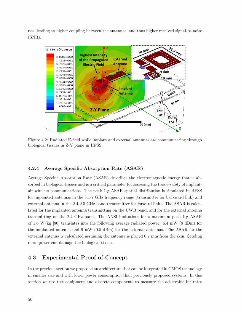
nas, leading to higher coupling between the antennas, and thus higher received signal-to-noise(SNR).
External Antenna
Highest Intensity of the Propagated
Electric-Field
0 35 70 (mm)
SkinFat
Bone
X
Brain
DuraCSF
Z-Y Plane
Y
Z
Implant Antenna
30 mm26.3 mm
10 mm
9 mm
Figure 4.2: Radiated E-field while implant and external antennas are communicating throughbiological tissues in Z-Y plane in HFSS.
4.2.4 Average Specific Absorption Rate (ASAR)
Average Specific Absorption Rate (ASAR) describes the electromagnetic energy that is ab-sorbed in biological tissues and is a critical parameter for assessing the tissue-safety of implant-air wireless communications. The peak 1-g ASAR spatial distribution is simulated in HFSSfor implanted antennas in the 3.1-7 GHz frequency range (transmitter for backward link) andexternal antenna in the 2.4-2.5 GHz band (transmitter for forward link). The ASAR is calcu-lated for the implanted antenna transmitting on the UWB band, and for the external antennatransmitting on the 2.4 GHz band. The ANSI limitations for a maximum peak 1-g ASARof 1.6 W/kg [80] translates into the following average radiated power: 6.4 mW (8 dBm) forthe implanted antenna and 9 mW (9.5 dBm) for the external antennas. The ASAR for theexternal antenna is calculated assuming the antenna is placed 0.7 mm from the skin. Sendingmore power can damage the biological tissues.
4.3 Experimental Proof-of-Concept
In the previous section we proposed an architecture that can be integrated in CMOS technologyin smaller size and with lower power consumption than previously proposed systems. In thissection we use test equipment and discrete components to measure the achievable bit rates
50
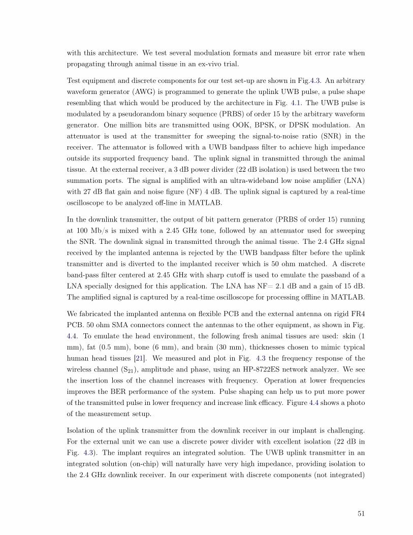
with this architecture. We test several modulation formats and measure bit error rate whenpropagating through animal tissue in an ex-vivo trial.
Test equipment and discrete components for our test set-up are shown in Fig.4.3. An arbitrarywaveform generator (AWG) is programmed to generate the uplink UWB pulse, a pulse shaperesembling that which would be produced by the architecture in Fig. 4.1. The UWB pulse ismodulated by a pseudorandom binary sequence (PRBS) of order 15 by the arbitrary waveformgenerator. One million bits are transmitted using OOK, BPSK, or DPSK modulation. Anattenuator is used at the transmitter for sweeping the signal-to-noise ratio (SNR) in thereceiver. The attenuator is followed with a UWB bandpass filter to achieve high impedanceoutside its supported frequency band. The uplink signal in transmitted through the animaltissue. At the external receiver, a 3 dB power divider (22 dB isolation) is used between the twosummation ports. The signal is amplified with an ultra-wideband low noise amplifier (LNA)with 27 dB flat gain and noise figure (NF) 4 dB. The uplink signal is captured by a real-timeoscilloscope to be analyzed off-line in MATLAB.
In the downlink transmitter, the output of bit pattern generator (PRBS of order 15) runningat 100 Mb/s is mixed with a 2.45 GHz tone, followed by an attenuator used for sweepingthe SNR. The downlink signal in transmitted through the animal tissue. The 2.4 GHz signalreceived by the implanted antenna is rejected by the UWB bandpass filter before the uplinktransmitter and is diverted to the implanted receiver which is 50 ohm matched. A discreteband-pass filter centered at 2.45 GHz with sharp cutoff is used to emulate the passband of aLNA specially designed for this application. The LNA has NF= 2.1 dB and a gain of 15 dB.The amplified signal is captured by a real-time oscilloscope for processing offline in MATLAB.
We fabricated the implanted antenna on flexible PCB and the external antenna on rigid FR4PCB. 50 ohm SMA connectors connect the antennas to the other equipment, as shown in Fig.4.4. To emulate the head environment, the following fresh animal tissues are used: skin (1mm), fat (0.5 mm), bone (6 mm), and brain (30 mm), thicknesses chosen to mimic typicalhuman head tissues [21]. We measured and plot in Fig. 4.3 the frequency response of thewireless channel (S21), amplitude and phase, using an HP-8722ES network analyzer. We seethe insertion loss of the channel increases with frequency. Operation at lower frequenciesimproves the BER performance of the system. Pulse shaping can help us to put more powerof the transmitted pulse in lower frequency and increase link efficacy. Figure 4.4 shows a photoof the measurement setup.
Isolation of the uplink transmitter from the downlink receiver in our implant is challenging.For the external unit we can use a discrete power divider with excellent isolation (22 dB inFig. 4.3). The implant requires an integrated solution. The UWB uplink transmitter in anintegrated solution (on-chip) will naturally have very high impedance, providing isolation tothe 2.4 GHz downlink receiver. In our experiment with discrete components (not integrated)
51

Arbitrary Wave
Generator
IR-UWB Pulses
Attenuator
LNA 2.4 GHz
Real-time Oscilloscope
Attenuator
OOK Data
OOKBPSKDPSK
Bone
He
ad
La
ye
rs
Skin
Fat
Brain
Mixer
LNAUWB
3dB Power Divider
22 dB
Setup Gain=15 dB, NF=2.1 dB
Gain=27 dBNF=4 dB
Antenna
Isolation
Antenna
UWB-BPF
2.45GHz-BPF
Real-time Oscilloscope
PRBS100
Mb/s
Carrier2.4 GHz
(a)
2 3 4 5 6 7 8 9 10
0
-5
-10
-15
-20
0
-20
-40
-60
-80
Frequency (GHz)
Am
plit
ud
e o
f S 2
1 (
dB
)
Ph
ase
of
S 21 (
Rad
ian
)
(b)
Figure 4.3: (a) Block digram of the system level implementation of the proposed link, and (b)the measured frequency response of the wireless channel.
we emulate this high isolation via a UWB bandpass filter (see Fig. 4.3). The bandpass filterrejects the 2.4 GHz downlink signal, effectively routing all energy to the 2.4 GHz receiver.
To isolate the 2.4 GHz downlink receiver from flooding by the UWB transmitter, we use pulseshaping. Figure 4.5 shows the measured UWB pulse with OOK modulation at the outputof the AWG, as captured by the real-time oscilloscope. In Fig. 4.5 we see the spectrum forthe UWB signal. The pulse is shaped to place energy between 3.1-7 GHz, and to introduce anotch at 2.45 GHz, yielding good isolation between uplink and downlink.
The final determination of the effectiveness of isolation is the bit error rate performance ofuplink and downlink. We will see in the following sections that measured BER is close totheoretical limits, hence crosstalk is negligible.
52

Setup
Arbitrary Wave Generator
Antennas & Head tissues
PRBS
Real-time Oscilloscope
2.4 GHz Signal Generator
Brain
Bone
FatSkin
Implant Antenna
External Antenna
Figure 4.4: Set-up for data communications.
4.4 Experimental Results
To provide the systems designer maximum flexibility this architecture has the added advantageof supporting three signaling methods: OOK, BPSK and DPSK. Each modulation format isbriefly described, including the required receiver.
Figure 4.5: Measurment result: (a) OOK modulation waveform in AWG output for 500 Mbps(b) its spectrum.
53

(a)
(b)
(c)
Figure 4.6: Reciver blocks implemented in MATLAB (off-line processing) for (a) BPSK, (b)DPSK, and (c) OOK.
4.4.1 BPSK Modulation
Phase-Shift Keying (PSK) is a modulation scheme in which the phase of a signal is varied totransmit information. In binary phase shift keying (BPSK) the phase of the signal is varied by180 degrees with the polarity of the binary data. BPSK is detected by using a matched filteror the equivalent correlation receiver. To detect the received signal coherently a templatepulse is needed for the correlation receiver as shown in Fig. 4.6. To generate the optimaltemplate, the frequency response of the channel must be known [11]; the measured frequencyresponse of the channel is plotted in Fig. 4.3. The transmitted, received and detected signalsare shown in Fig. 4.7a for 500 Mbps and SNR = 20 dB.
4.4.2 DPSK Modulation
DPSK modulation transmits data on changes in phase from symbol to symbol. Because thedata are detected by correlation with a delayed version of the received waveform, the datamust first be encoded in a differential fashion [11]. Self-homodyne detection (i.e. correlationwith a delayed version of the received signal), is followed by integration and detection blocksas shown in Fig. 4.6b. The transmitted, received and detected signals are shown in Fig. 4.7bfor 500 Mbps and SNR = 20 dB.
54

4.4.3 OOK Modulation
On-Off Keying (OOK) is the simplest form of amplitude-shift keying modulation. The presenceof a waveform for a specific duration represents a binary one, while its absence for the sameduration represents a binary zero [11]. For detection, the received signal is multiplied by itself,integrated and detected as shown in Fig. 4.6c. The transmitted, received and detected signalfor the backward link are shown in Fig. 4.7a for 500 Mbps and SNR = 20 dB. Also, the datatransmission for forward link is presented in Fig. 4.7d for 100 Mbps and SNR = 20 dB.
Figure 4.6 shows the block diagram of the receiver systems for different modulations, performedoffline in MATLAB on data captured by the real-time oscilloscope. For the backward link,Fig. 4.7 shows the modulated waveforms with random digital data at the transmitter, thereceiver, and following detector. In Fig. 4.7 “Transmitted signal” is the waveform modulatedwith a PRBS of order 15 and 1 million bits length for different modulations which is uploadedin AWG. “Received signal” is the signal which is captured by real-time oscilloscope. “Filteredsignal” is the captured signal after the band-pass filter in Fig. 4.6. “Integrated signal” isthe output of the integrator (a RC low-pass filter) in Fig. 4.6. The red dash-lines in the“Integrated signal” are the sampling times. In order to detect transmitted data, the sampledsignal (dashed red line) is compared with a threshold value. “Transmitted signal” in Fig. 4.7drefer to the forward link at output signal of the mixer which is captured by the real-timeoscilloscope. “Received signal”, “Filtered signal” and “Integral Signal” are similar to thosediscussed for the backward link. Discussions about different modulations are provided below.
4.5 Data Rates and BER Performance
Recently data transmission performance at 80 Mbps was investigated for wireless implant-to-air data communications for gastro applications [44]. In that work, a multiband orthogo-nal frequency division modulation (MB-OFDM) was used, which consumes more power thanimpulse-radio UWB. We were able to push data rates above this previous maximum of 80Mbps [45]. We achieved 2 Gb/s for neural recording systems (downlink) due to the following.1) For gastro application, the distance between the TX and RX antennas is 33 mm. The worstcase separation for neural recordings is around 10 mm. Smaller separations leads to less signalattenuation.
2) In [44] the transmission powers were chosen to respect the FCC limitations assuming anten-nas are in free-space. This level was pessimistic as it did not take into account insertion losscaused by biological tissues The true limit should balance avoiding biological tissue damage,while still respecting FCC limitations after attenuation.
3) Antennas in [44] are designed for free-space, resulting in much greater channel insertion
55

Transmitted
signal
Received
signal
Filtered
signal
Integrated
signal
Detected
data
1 1 0 0 10
0 1 1 0 0 10
3 5 7 9 111Time (ns)
4 6 8 10 1220
(a)
Transmitted
signal
Received
signal
Filtered
signal
Integrated
signal
Detected
data
1 1 0 0 10
Time (ns)
0 1 1 0 0 10
3 5 7 9 111 4 6 8 10 1220
(b)
Transmitted
signal
Received
signal
Filtered
signal
Integrated
signal
Detected
data
1 1 0 0 10
0 1 1 0 0 1
3 5 7 9 111Time (ns)
4 6 8 10 1220
(c)
Transmitted
signal
Received
signal
Filtered
signal
Integrated
signal
Detected
data
1 1 0 0 10
20 30 40 50 6010Time (ns)
1 1 10
1 1 1 0 1 10 0 0 1
70 80 900 100
(d)
Figure 4.7: Different stages of data transmission for (a) BPSK uplink, (b) DPSK uplink, (c)OOK uplink, and (d) OOK downlink.
56
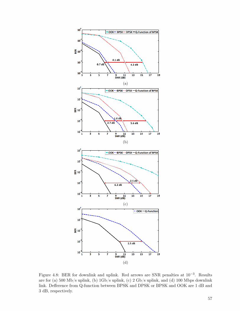
(a)
(b)
(c)
(d)
Figure 4.8: BER for downlink and uplink. Red arrows are SNR penalties at 10−3. Resultsare for (a) 500 Mb/s uplink, (b) 1Gb/s uplink, (c) 2 Gb/s uplink, and (d) 100 Mbps downlinklink. Defference from Q-function between BPSK and DPSK or BPSK and OOK are 1 dB and3 dB, respectively.
57
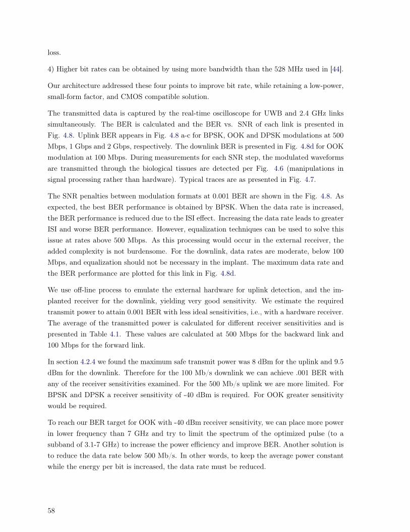
loss.
4) Higher bit rates can be obtained by using more bandwidth than the 528 MHz used in [44].
Our architecture addressed these four points to improve bit rate, while retaining a low-power,small-form factor, and CMOS compatible solution.
The transmitted data is captured by the real-time oscilloscope for UWB and 2.4 GHz linkssimultaneously. The BER is calculated and the BER vs. SNR of each link is presented inFig. 4.8. Uplink BER appears in Fig. 4.8 a-c for BPSK, OOK and DPSK modulations at 500Mbps, 1 Gbps and 2 Gbps, respectively. The downlink BER is presented in Fig. 4.8d for OOKmodulation at 100 Mbps. During measurements for each SNR step, the modulated waveformsare transmitted through the biological tissues are detected per Fig. 4.6 (manipulations insignal processing rather than hardware). Typical traces are as presented in Fig. 4.7.
The SNR penalties between modulation formats at 0.001 BER are shown in the Fig. 4.8. Asexpected, the best BER performance is obtained by BPSK. When the data rate is increased,the BER performance is reduced due to the ISI effect. Increasing the data rate leads to greaterISI and worse BER performance. However, equalization techniques can be used to solve thisissue at rates above 500 Mbps. As this processing would occur in the external receiver, theadded complexity is not burdensome. For the downlink, data rates are moderate, below 100Mbps, and equalization should not be necessary in the implant. The maximum data rate andthe BER performance are plotted for this link in Fig. 4.8d.
We use off-line process to emulate the external hardware for uplink detection, and the im-planted receiver for the downlink, yielding very good sensitivity. We estimate the requiredtransmit power to attain 0.001 BER with less ideal sensitivities, i.e., with a hardware receiver.The average of the transmitted power is calculated for different receiver sensitivities and ispresented in Table 4.1. These values are calculated at 500 Mbps for the backward link and100 Mbps for the forward link.
In section 4.2.4 we found the maximum safe transmit power was 8 dBm for the uplink and 9.5dBm for the downlink. Therefore for the 100 Mb/s downlink we can achieve .001 BER withany of the receiver sensitivities examined. For the 500 Mb/s uplink we are more limited. ForBPSK and DPSK a receiver sensitivity of -40 dBm is required. For OOK greater sensitivitywould be required.
To reach our BER target for OOK with -40 dBm receiver sensitivity, we can place more powerin lower frequency than 7 GHz and try to limit the spectrum of the optimized pulse (to asubband of 3.1-7 GHz) to increase the power efficiency and improve BER. Another solution isto reduce the data rate below 500 Mb/s. In other words, to keep the average power constantwhile the energy per bit is increased, the data rate must be reduced.
58

Table 4.1: Average transmitted power at .001 BER for different receiver sensitivities for 500Mb/s uplink and 100 Mb/s downlink
Receiver Sensitivity -67 dBm -40 dBm -30 dBm -15 dBmOOK -17.3 9.7 19.7 34.7
UWB TX-Power (dBm) BPSK -25.6 1.4 11.4 26.4DPSK -21.46 5.54 15.54 30.54
Receiver Sensitivity -47 dBm -40 dBm -30 dBm -15 dBm2.4 GHz-link TX-Power (dBm) OOK - 25.7 -18.7 -8.7 6.3
4.6 Conclusion
Designing a reliable wireless high speed data link in the presence of lossy biological tissues is achallenging task. We proposed a wireless communications architecture for implanted systemsthat simultaneously stimulate neurons and record neural responses. The proposed full-duplexdual-band transceiver configuration avoids using a circulator or a diplexer and includes onlyone data link which makes the implanted integrated transceiver more compact and powerefficient. This architecture supports large numbers of electrodes (>500), providing 100 Mb/sfor the downlink of stimulation signals, and Gb/s for the uplink neural recordings.
We presented an ex-vivo experiment using discrete components achieving Gb/s uplink rates.The BER performance of BPSK, OOK and DPSK were investigated with the 5th derivativeof a Gaussian pulse as the uplink UWB waveform. The BER performance of OOK wasexamined for the downlink. A receiver sensitivity of -40 dBm is required for BPSK and DPSKto achieve BER of 10−3 at 500 Mbps for the uplink. For the OOK downlink at 100 Mbps areceiver sensitivity of 15 dBm is sufficient.
59


Chapter 5
A Fully Integrated Full-Duplex HighSpeed Transceiver for Multi-SitesStimulating and Recording NeuralImplants
Abstract
In this chapter, published in [J4], we present circuit level design of the proposed full-duplex architecture presented in the previous chapter. The transmitter (TX) and receiver(RX) share a single antenna to reduce implant size and complexity. The TX uses impulseradio ultra-wide band (IR-UWB) based on an edge combining approach, and the RX usesa novel 2.4 GHz on-off keying (OOK) receiver. Proper isolation (>20 dB) between theTX and RX path is implemented 1) by shaping the transmitted pulses to fall within theunregulated UWB spectrum (3.1-7 GHz), and 2) by space-efficient filtering (avoiding acirculator or diplexer) of the downlink OOK spectrum in the RX low-noise amplifier. TheUWB 3.1-7 GHz transmitter can use either OOK or binary phase shift keying (BPSK)modulation schemes. The proposed full-duplex transceiver (FDT) provides dual band 500Mbps TX uplink data rate and 100 Mbps RX downlink data rate, and it is fully integratedinto standard TSMC 0.18 µm CMOS within a total size of 0.485 mm2. The total measuredpower consumption is 10.4 mW in full duplex mode (5 mW at 100 Mbps for RX, and 5.4mW at 500 Mbps or 10.8 pJ/bit for TX).
5.1 Introduction
In this chapter the main contribution is:
61
- Circuit level implementation of a power efficient UWB pulse shaper on CMOS technol-ogy.
In recent years, several neural recording and stimulating systems have been developed to pro-vide a wireless neural interface [3,81] to the brain. Nevertheless, these devices are difficult tocommercialize in part due to lack of 1) a straightforward design to support the required func-tionalities, 2) sufficient miniaturization, and 3) a reliable low-power high data rate interfacebetween implants and external devices.
A high data rate wireless interface is the key for addressing the challenges and requirements ofnext generation brain interfacing technology. Recently, the development of high-density neuralprobes (> 500 sites) using standard microelectronic technology has opened up new opportu-nities for high-resolution mapping of brain functions [82]. High-resolution visual prostheticsystems have been designed as well for stimulating the retina from as much as 256 sites [83].Furthermore, a new class of neuroprosthetic devices has recently been introduced to inter-act with neural tissues in two ways (stimulation and recording). Such bidirectional systemsare significant as they establish a closed-loop connection between the brain and a prostheticdevice, leading to the restoration of broken neural connections or to a significant improve-ment of several therapies against chronic neural diseases [84]. As we mentioned in Chapter 4,conventionally, separated data transmission links have been used for forward and backwardtelemetry in such implantable systems. A third and seperate link is typically used to transmitpower through inductive coupling [10,63]. Therefore, as many as three separate wireless linksare often included for communicating and powering up the implanted device. Some attemptshave been made to decrease the number of links for power and data transmissions. Inductivelinks have been utilized either for forward and backward telemetry or combining both into thesame link, providing data rates on the order of a few Mbps [10]. Such strategies are proneto increased complexity and interference because of the mutual inductance with the powerlink. Moreover, having three separate (independent) links complicates miniaturization of theimplantable devices [10,63].
Attempts have been made to combine the forward or the backward telemetry link with thepower transmission link by modulating the power carrier signal with forward/backward data[85, 86]. However, such approaches decrease the efficiency of the power transmission linkand confine transmissions to low data rates. On the other hand, recent implementationsof inductive power links utilize multicoil resonance-based structure enabling higher powertransfer efficiency and higher power delivery across longer distances [87,88]. Resonance-basedpower links inhibit frequency and phase variations of the transferred signal because of the highquality resonators located between the TX and RX coils. Therefore, frequency shift keying(FSK) and phase shift keying (PSK) modulations cannot be utilized for transferring data bythe resonance-based power links. Although amplitude shift keying (ASK) modulation of the
62

carrier signal has been demonstrated for transferring data within a resonance-based powerlink, resistance against fast amplitude variation yields low data rates [89, 90]. In general, thereliability of the modulated resonance-based link is worse than conventional 2-coil inductivelinks, as it experiences lower power transfer efficiency and more variability of power delivery.
In this chapter, we propose an implantable full duplex RF transceiver enabling high-speedbidirectional data transmission. The chapter is organized as follows; section 5.2 presents anoverview of the principle of the proposed data interference. Section 5.3 presents the full-duplextransceiver circuit design. The full-duplex transceiver experimental results obtained with thefabricated integrated circuit are presented in section 5.4. Finally, conclusions are drawn insection 5.5.
5.2 System overview
The number of stimulating and/or recording electrodes included in brain machine interface(BMI) systems is constantly increasing in order to provide high resolution, and enhancing ourunderstanding of brain functions. This number is expected to soon reach one thousand as indi-cated by recent trends [91,92].The uplink data rate requirement for 1000 probes easily reaches500 Mbps assuming a 40 ksps sampling rate × 12 bits of resolution per sample + 5% overhead= 504 Mbps. The required downlink data rate is estimated to 4 words per biphasic pulse ×25 bits/word × 1000 channels × 400 refresh/s = 40 Mbps [83,85]. Therefore, a high data ratewireless interface design is the key for implementing BMI systems. Figure 5.1 presents a blockdiagram of the proposed full duplex data transceiver, which enables simultaneous transmissionand reception of data over a unique RF link using the same antenna (to decreases the sizeof the implanted device). Conventionally, passive circulators or duplexers have been utilizedfor implementing full-duplex transceivers [93]. Such multi-port waveguides are composed ofmagnetized ferrite materials that can route signals from the transmitter to the antenna, andfrom the antenna to the receiver, without allowing signals to pass directly from transmitter toreceiver. In CMOS technology, active circulators are used instead of passive ones as CMOSis incompatible with magnetized ferrite material structures. Active circulators, typically com-posed of amplifiers and a power divider/combiner to form an active quasi-circulator module,attenuate the signal by at least 3 dB [69]. Moreover, such components are bulky and powerhungry. A conventional strategy for implementing a full-duplex transceiver without using anactive circulator is to employ two sharp band-pass filters to separate the transmit and receivefrequency bands [69,93]. These two frequency bands must be very close to be covered by thesame antenna. However, having two dedicated high-order filters has drawbacks: 1) it is areaconsuming, 2) it attenuates the passing signal, and 3) it increases the noise figure of the re-ceiver. Our proposed design separates the transmit and receive band by carefully shaping thetransmitted signal, and filtering the received signal directly in the low-noise amplifier (LNA)using cascode transistors with passive matching filters. The block diagram of the proposed
63

Figure 5.1: Block diagram of an implantable neural recording and stimulating device includingan inductive power link and the proposed full duplex transceiver.
wireless interface is presented in Fig. 5.1. This figure shows the block diagrams of the dataand power links, and all integrated building blocks of the Full-Duplex Transceiver (FDT).The proposed integrated FDT design is small and low-power, which makes it suitable for im-plantable applications. UWB 3.1-7 GHz and 2.4 GHz IMS bands are unlicensed bands readilyavailable for use in low-power biomedical applications.
The proposed full duplex transceiver includes a 2.4 GHz on-chip OOK receiver and a UWB3.1-7 GHz transmitter supporting both OOK and BPSK modulations. A circuit schematicof the FDT is shown in Fig. 5.2. The 2.4 GHz receiver is designed to support wirelessdownlink telemetry for neural stimulation applications, and the 3.1-7 GHz UWB transmitteris designed to support wireless uplink telemetry of high-density neural recording systemspresenting very high channel counts. Since both the receiver and the transmitter use the sameantenna and communicate simultaneously into different frequency bands for this application,our solution decreases design complexity, decreases the total size of the implanted device,decreases interference between the up and down links, and eases the implementation of theimplanted system.
5.3 Full-Duplex Transceiver Design
The design of a fully integrated implantable full-duplex transceiver must minimize the powerconsumption and size of the transceiver. Implantable BMI systems, including high-densityneural recording/stimulating probes, require a wireless transceiver supporting simultaneouslythousands of stimulation and recording channels. The high-performance, implantable transceivermust support a high data rate uplink (body to external) and a moderate data rate downlink(external to body). Our proposed transceiver uses the UWB band (3.1-7 GHz) for the uplink,
64

Figure 5.2: The integrated circuit building blocks of the proposed implantable wireless inter-face consists of a new full duplex data transceiver.
and the 2.4-2.5 GHz IMS band for the downlink. Since regulatory agencies impose a limiton the total radiated power for these unlicensed bands, the transmitter and receiver must bedesigned to work with reduced power levels. Our pulse shaping approach for the UWB bandhas four main advantages: 1) power efficient exploitation of the FCC mask, 2) isolation fromthe downlink that enables full-duplex operation, 3) avoidance of a circulator or a duplexerwhich reduces loss, power and size, and 4) concentration of power in the lower portion of theUWB band where the biological channel imposes less loss [51].
5.3.1 UWB Transmitter Design
A carrierless, edge-combining impulse UWB transmitter topology offers a simple and low-power circuit implementation [67,94] as it avoids the need for an up conversion mixer, whoseCMOS implementation is known to be power hungry [3, 14, 77]. While small in size, it canreach high data rate. Both BPSK and OOK modulation schemes can be supported withthis design, offering flexibility in trading off power consumption, and desired bit error rate(BER) performance [45]. The UWB pulses are shape by adjusting the amplitude and the timeduration of the 5th derivatives of a Gaussian pulse generated by a customized circuit insidethe transmitter, as shown in Fig. 5.3. Such a design yields a simple transmitter, reducing thedie size compared to traditional methods using a high-pass filter for shaping [3,95]. OOK andBPSK are easily supported. The UWB transmitter circuit uses regular CMOS logic gates, suchas inverters and NORs, and NMOS transistors, which sum and amplify the UWB impulses asshown in Fig. 5.3a. This design provides a high date while the size and power consumptionare low. The UWB pulse is generated by summing several time-shifted glitch pulses. Fourinverter-based delay lines shift the generated pulses. The four shifted impulses are output viatransistors M1-M4, to form the required UWB signal data transmission. OOK modulationis produced when only the top half of the circuit is active. For BPSK modulation, the samecircuit with a different output configuration (bottom half of the circuit depicted in Fig. 5.3a)
65

(a)
(b)
Figure 5.3: Up-link a) transmitter circuit enabling to generate UWB signal for transmittingdata using OOK and BPSK modulations, and b) size and power efficient transmitter circuitenabling to produce OOK signal.
produces impulses with a 180° phase difference using the top and bottom half circuits. Digital“1” are produced by the top circuit, while digital “0”, which corresponds to the 180°-phaseshifted impulses, are produced by the bottom circuit. The performance obtained with bothmodulation schemes are compared in section 5.4. The transmitter presented in Fig. 5.3b isdesigned and fabricated to limit transmitter size and power consumption and supports OOKmodulation only. One impulse is generated and shifted by a delay line, giving less shapingflexibility than the design of Fig. 5.3a. The shifted impulse is applied to the output transistorsto produce the UWB signal.
5.3.2 2.4-GHz Receiver Design
The block diagram of the proposed 2.4 GHz OOK receiver is shown in Fig. 5.2. The inputsignal is amplified by the low noise amplifier (LNA), and then down-converted to baseband,similarly to the low-power system reported in [96]. The schematic of the receiver is shown
66
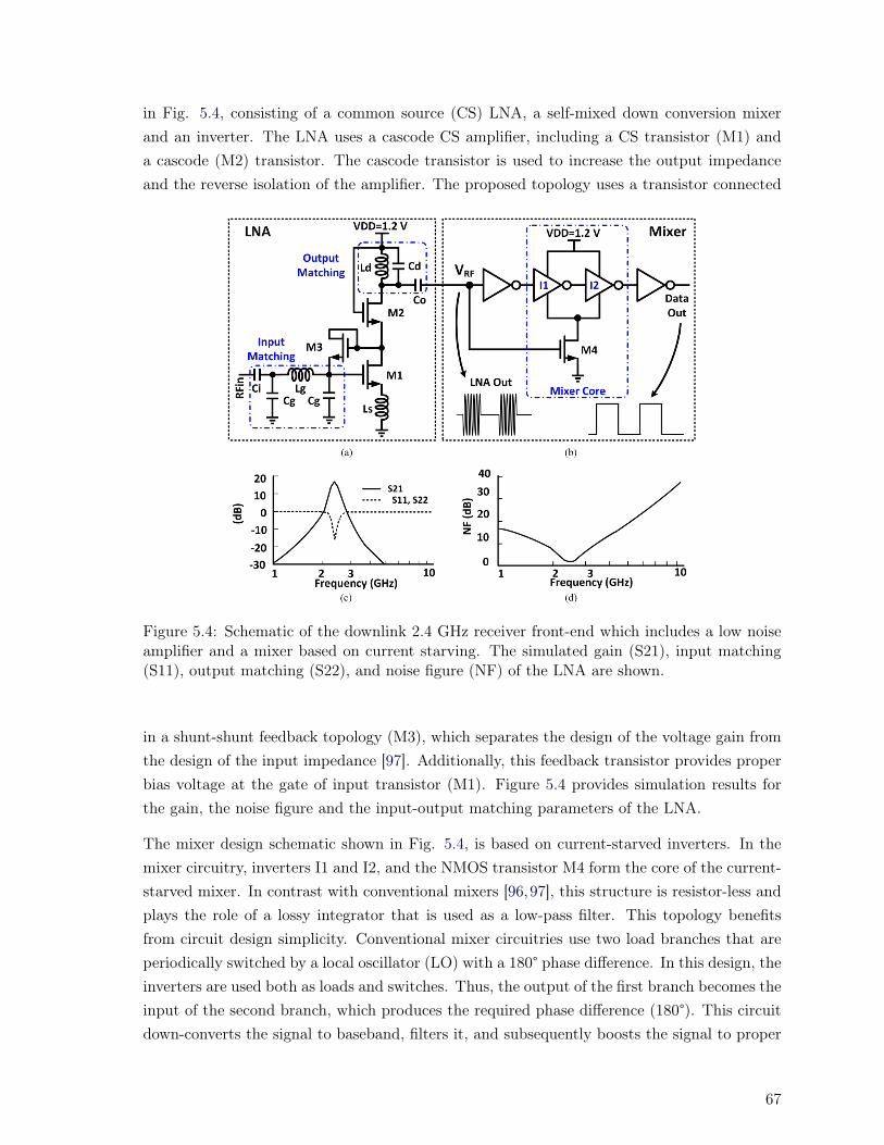
in Fig. 5.4, consisting of a common source (CS) LNA, a self-mixed down conversion mixerand an inverter. The LNA uses a cascode CS amplifier, including a CS transistor (M1) anda cascode (M2) transistor. The cascode transistor is used to increase the output impedanceand the reverse isolation of the amplifier. The proposed topology uses a transistor connected
Figure 5.4: Schematic of the downlink 2.4 GHz receiver front-end which includes a low noiseamplifier and a mixer based on current starving. The simulated gain (S21), input matching(S11), output matching (S22), and noise figure (NF) of the LNA are shown.
in a shunt-shunt feedback topology (M3), which separates the design of the voltage gain fromthe design of the input impedance [97]. Additionally, this feedback transistor provides properbias voltage at the gate of input transistor (M1). Figure 5.4 provides simulation results forthe gain, the noise figure and the input-output matching parameters of the LNA.
The mixer design schematic shown in Fig. 5.4, is based on current-starved inverters. In themixer circuitry, inverters I1 and I2, and the NMOS transistor M4 form the core of the current-starved mixer. In contrast with conventional mixers [96,97], this structure is resistor-less andplays the role of a lossy integrator that is used as a low-pass filter. This topology benefitsfrom circuit design simplicity. Conventional mixer circuitries use two load branches that areperiodically switched by a local oscillator (LO) with a 180° phase difference. In this design, theinverters are used both as loads and switches. Thus, the output of the first branch becomes theinput of the second branch, which produces the required phase difference (180°). This circuitdown-converts the signal to baseband, filters it, and subsequently boosts the signal to proper
67

(a)
Figure 5.5: The chip micrograph of the proposed full duplex transceiver fabricated in a TSMC0.18 µm CMOS technology, with a total die size of 1×0.8 mm2.
digital levels using an inverter. Figure 5.4 shows the simulated frequency response of the LNA.As can be seen, input signals at frequencies above 3 GHz are filtered out by the LNA. Thus,as will be shown in section 5.4, by allocating the transmitted signal power between 5 and 6GHz, and by filtering such signal directly at the input of the LNA, the transmitted signal isefficiently attenuated by more than 30 dB by the LNA.
5.4 Full-Duplex Transceiver Measurement Results
Figure 5.5 shows a chip micrograph of the proposed full duplex transceiver fabricated in aTSMC 0.18 µm CMOS technology including the 2.4-GHz receiver (LNA, mixer and an outputbuffer) and the UWB transmitters (TX1 and TX2). The receiver size is 0.375 mm2. Thetransmitter sizes is 0.1 mm2 and 0.01 mm2 for TX1 and TX2, respectively.
To verify the functionality of the proposed full duplex transceiver, the implantable transceiverwas fabricated in TSMC 0.18 µm CMOS technology and tested in full-duplex mode. Discretecomponents and instruments were utilized as an external system to send and retrieve datafrom the FDT. Figure 5.6a and 5.6b represent the measurement setup block diagram andexperimental setup employed for characterizing the full-duplex data link. On the externalcontroller side, a 3 dB power divider is utilized between two summation ports, which presentan isolation of 22 dB. The UWB discrete receiver amplifies the received signal using an ultra-wideband LNA with a 27 dB flat gain and 4 dB noise figure. This signal is captured by a real-
68

(a)
(b)
Figure 5.6: a) Experimental setup block diagram showing the required equipment, and b) theexperimental measurement setup employed for characterizing the full-duplex data link.
time oscilloscope to be analyzed off-line in MATLAB. The 2.4 GHz transmitter is implementedby a mixer, which mixes the output of a pseudorandom binary sequence (PRBS) with a 2.4 GHzsinusoidal signal source to generate a random OOK signal. On the implanted side (Fig. 5.6a),the integrated transmitter circuit generates UWB pulses, according to the selected modulationtype (OOK or BPSK). The transmitter pseudorandom input data sequence is generated byan external PRBS generator. The signal-to-noise ratio (SNR) of the UWB transceiver ismeasured on the receiver side. The 2.4 GHz integrated receiver amplifies the received OOKsignal and digitizes it. The digital data is captured at the output of the receiver by a real-timeoscilloscope, and analyzed offline in MATLAB to calculate the BER. The biological tissues of
69

the head are emulated using fresh animal tissue layers: skin (1 mm), fat (1 mm), bone (4 mm),and brain (30 mm). These tissue thicknesses are chosen to mimic typical human head tissues[21]. To emulate a complete channel, an implanted antenna and an external antenna [51] areconnected to the other equipment by 50 Ω SMA connectors. Such a channel was characterizedpreviously in [51], showing that as expected, the insertion loss of the channel increases withfrequency. At low frequencies the channel experiences no distortion, while at high frequenciesinter-symbol interference may occur (leading to performance deterioration). Lower loss isexpected in the biological channel at lower frequency, improving BER. So, the efficiency ofthe link is increased by putting more power of the transmitted pulse at lower frequencies bypulse shaping. The spectrum of the transmitted UWB signal must be located in the desiredfrequency band of 3.1-7 GHz to avoid coupling into the LNA of the 2.4-GHz receiver. Tocapture the spectrum of the UWB signal, the output of the transmitter is measured using areal-time oscilloscope and Fourier transformed. The results are presented in Fig. 5.4-5.7. Asshown the Fig. 5.7a and 5.7b, the spectrums of the UWB signals are between 3.1 and 7 GHzfor both implemented transmitters (TX1 and TX2, respectively). As can be seen in Fig. 5.7,there is a isolation of more than 20 dB between downlink and uplink. The proposed UWBtransmitter uses edge-combining (based on short pulse delays) to avoid using a mixer, anoscillator and a band pass filter, thus lowering power consumption [67,75]. A PRBS sequenceis used for testing the transmitters. At the external receiver of the uplink, the data is capturedby a real-time oscilloscope to find BER at 500 Mbps. Figure 5.8a shows the measured outputof the fabricated UWB transmitters TX1 and TX2. As described previously, when in OOKmode, the transmitters transmit impulses only when there are digital “1” to transmit, otherwiseno power is transmitted. For BPSK mode, the transmitter produces impulses for digital “0”and “1”. A digital “0” is represented by 180°-phase shifted impulse, compared to a digital“1”. The measured power consumption of both fabricated UWB transmitters are 5.4 mW and3.5 mW for TX1 and TX2, respectively for OOK at 500 Mbps. Transmitter TX1 consumes11 mW in BPSK mode at 500 Mbps. These measurements use antennas with 50 Ω matchedimpedance [51]. Therefore, the input of the LNA is matched with a 50 Ω impedance at 2.4GHz. To reach good input and output impedance matching, an off-chip matching network(capacitors and inductors) is used in the design of the 2.4 GHz receiver. On the implantedside, matching the LNA input impedance with a 50 Ω characteristic impedance, requires seriesinductance and capacitance. A parallel LC tank is utilized at the output stage of the LNA(Fig. 5.4) in order to obtain the desired gain, and to achieve proper impedance matchingaround 2.45 GHz. The three required on-chip inductors of the LNA are designed using HFSS,a finite element solver, and then imported into Cadence Virtuoso for completing the layoutof the chip. The TSMC 0.18 µm CMOS layer specifications are used for simulating theinductors inside HFSS. The inductors are designed for maximizing the quality factors whileachieving small size according to the methodology described in [98]. A minimum 50 µm gapis introduced between the inductors and other circuit components to decrease electromagnetic
70
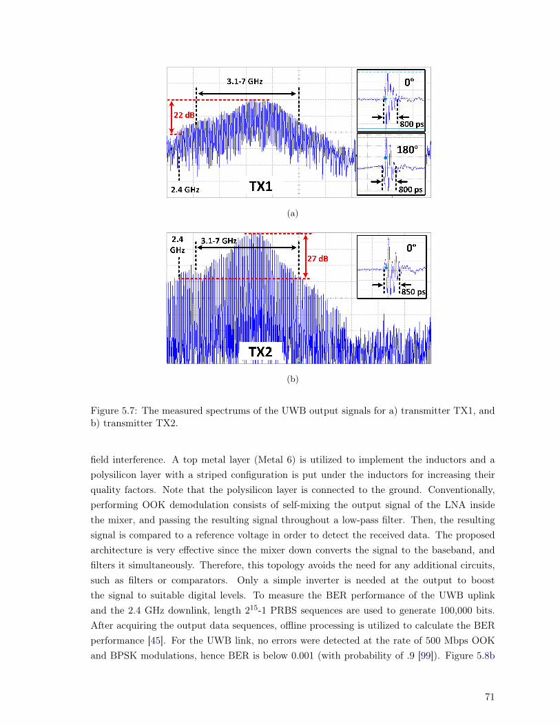
(a)
(b)
Figure 5.7: The measured spectrums of the UWB output signals for a) transmitter TX1, andb) transmitter TX2.
field interference. A top metal layer (Metal 6) is utilized to implement the inductors and apolysilicon layer with a striped configuration is put under the inductors for increasing theirquality factors. Note that the polysilicon layer is connected to the ground. Conventionally,performing OOK demodulation consists of self-mixing the output signal of the LNA insidethe mixer, and passing the resulting signal throughout a low-pass filter. Then, the resultingsignal is compared to a reference voltage in order to detect the received data. The proposedarchitecture is very effective since the mixer down converts the signal to the baseband, andfilters it simultaneously. Therefore, this topology avoids the need for any additional circuits,such as filters or comparators. Only a simple inverter is needed at the output to boostthe signal to suitable digital levels. To measure the BER performance of the UWB uplinkand the 2.4 GHz downlink, length 215-1 PRBS sequences are used to generate 100,000 bits.After acquiring the output data sequences, offline processing is utilized to calculate the BERperformance [45]. For the UWB link, no errors were detected at the rate of 500 Mbps OOKand BPSK modulations, hence BER is below 0.001 (with probability of .9 [99]). Figure 5.8b
71

(a)
(b)
Figure 5.8: Measurement results of the full duplex transceiver including a) the transmittedUWB signals using OOK and BPSK modulation schemes (TX1 and TX2) at a rate of 500Mbps, and b) the generated 2.4 GHz OOK signal and detected data at a rate of 100 Mbps.
shows the measurements for the 2.4-GHz link for downlink transmission. These results includethe transmitted OOK signal (produced by mixing a 2.4 GHz carrier signal with a PRBS datasequence) and the digitized data at a rate of 100 Mbps in the integrated receiver. The outputsignals of the 2.4 GHz receiver are captured using a real-time oscilloscope. As with the UWBsetup, the BER was measure. No errors were observed for the 2.4 GHz downlink using OOKmodulation at a rate of 100 Mbps, hence BER is also below 0.001 (with probability of .9 [99]).The gain of the LNA was measured to be 13.7 dB using a spectrum analyzer. The measurednoise figure of the LNA is 2.6 dB. The power consumption of the receiver is measured at5 mW (4 mW for the LNA and 1 mW for the mixer). To capture the output data of the2.4-GHz receiver off-chip with test equipment, a chain of inverters is utilized as a buffer whichproperly charges and discharges the output pad of the chip at the rate of 100 Mbps. The
72

(a)
(b)
(c)
(d)
(e)
Figure 5.9: Block diagram of the UWB receivers (RX-UWB) for a) OOK, and b) BPSKmodulations. The measured eye diagrams for the transmitters TX1 in c) OOK mode, d)BPSK mode, and e) TX2 in OOK mode.
73
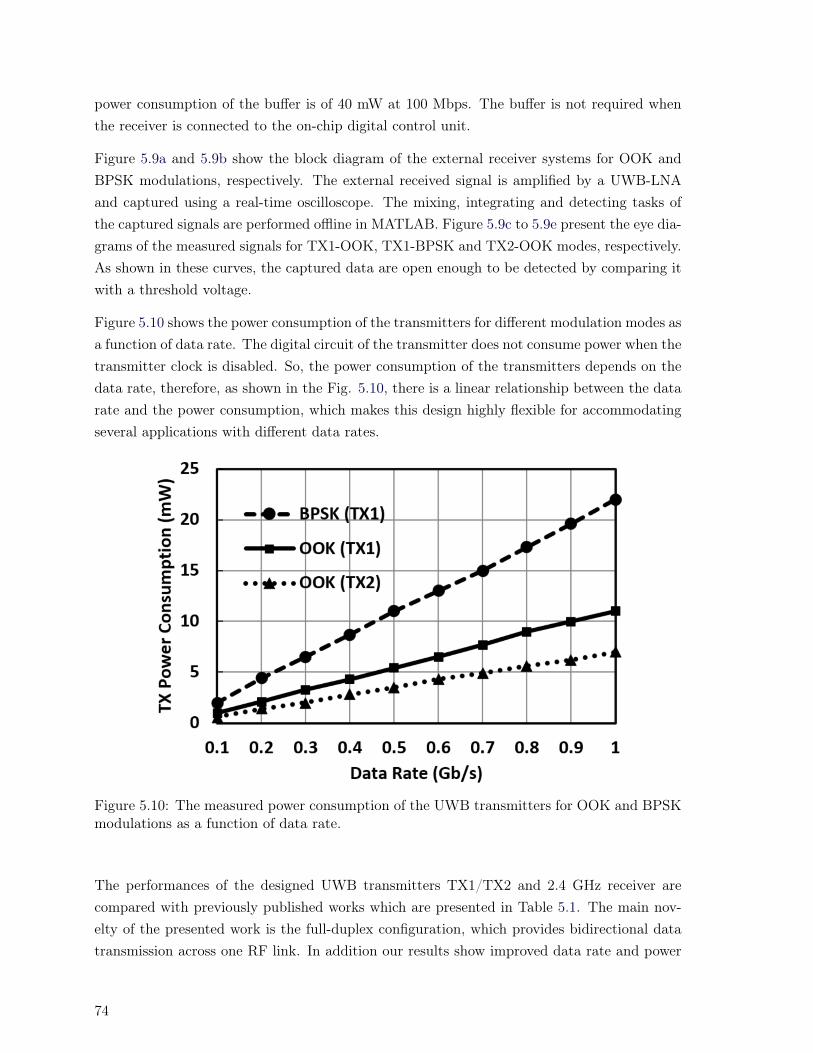
power consumption of the buffer is of 40 mW at 100 Mbps. The buffer is not required whenthe receiver is connected to the on-chip digital control unit.
Figure 5.9a and 5.9b show the block diagram of the external receiver systems for OOK andBPSK modulations, respectively. The external received signal is amplified by a UWB-LNAand captured using a real-time oscilloscope. The mixing, integrating and detecting tasks ofthe captured signals are performed offline in MATLAB. Figure 5.9c to 5.9e present the eye dia-grams of the measured signals for TX1-OOK, TX1-BPSK and TX2-OOK modes, respectively.As shown in these curves, the captured data are open enough to be detected by comparing itwith a threshold voltage.
Figure 5.10 shows the power consumption of the transmitters for different modulation modes asa function of data rate. The digital circuit of the transmitter does not consume power when thetransmitter clock is disabled. So, the power consumption of the transmitters depends on thedata rate, therefore, as shown in the Fig. 5.10, there is a linear relationship between the datarate and the power consumption, which makes this design highly flexible for accommodatingseveral applications with different data rates.
Figure 5.10: The measured power consumption of the UWB transmitters for OOK and BPSKmodulations as a function of data rate.
The performances of the designed UWB transmitters TX1/TX2 and 2.4 GHz receiver arecompared with previously published works which are presented in Table 5.1. The main nov-elty of the presented work is the full-duplex configuration, which provides bidirectional datatransmission across one RF link. In addition our results show improved data rate and power
74

Table 5.1: Comparison of previously published data links with our approaches.
Ref., Link Tech. Rate(Mbps) E.(pJ/b) B.W.(GHz) Modulation Die(mm2) P.(mW)[100], TX - 48 1040 3.2/3.8 FSK - 50[14], TX 0.35µm 30 161.7 3-5 OOK - 4.85[95], TX 0.35µm 160 10 3.1-5 PPM+OOK 8.87.2 1.6[67], TX 65nm 24 8.5 3.6-7.5 OOK 10.7 0.217[94], TX 65nm 200 45 3.1-5 PPM 2 9
This work, TX1 0.18µm 500 10.8 3.1-7 OOK, BPSK 0.1 5.4This work, TX2 0.18µm 500 7 3.1-7 OOK 0.01 3.5
Ref., Link Tech. Rate(Mbps) f(MHz) Modulation Coil/Ant. size Die(mm2) P.(mW)This work, RX 0.18µm 100 2400 OOK 11 cm2 0.375 5
[90], RX CMOS 1 8.4 ASK 1.351.35 cm2 - 0.1[85], RX 1.5µm 2.5 5/10 FSK 1.30.3 cm2 0.29 0.38[83], RX 0.18µm 2 22 DPSK dout=1 cm 0.520.62 5.7
consumption compared to previously published works.
5.5 Conclusion
We have presented an integrated, full-duplex transceiver to support high-density and bidi-rectional neural interfacing applications (high-channel count stimulating and recording). Itincludes a 2.4 GHz on-chip receiver with OOK modulation, and a UWB 3.1-7 GHz transmit-ter with selectable OOK or BPSK modulation. The implanted transceiver was fabricated inTSMC 0.18 µm CMOS technology. The uplink and downlink were characterized using biolog-ical materials emulating head tissue layers. The proposed full-duplex transceiver avoids theneed for a circulator or diplexer, as in conventional systems. The full-duplex functionalityis implemented by shaping the transmitted pulse. The impulse generator is based on edge-combining, to keep its spectrum inside the UWB band (3.1-7 GHz), and by matching onlythe 2.4 GHz input signal to the input of the LNA of the receiver. The receiver is designedfor wireless downlink telemetry of neural stimulation applications at data rates up to 100Mbps while consuming only 5 mW. The transmitter is designed for uplink telemetry of neuralrecording systems supporting data rate above 500 Mbps while consuming 5.4 mW.
75


Chapter 6
Flexible Sixteen Antenna Array forMicrowave Breast Cancer Detection
Abstract
Results from this chapter were published in [J5]. Radar based microwave imaging (MI)has been widely studied for breast cancer detection in recent times. Sensing dielectricproperty differences of tissues over a wide frequency band has been made possible byultra-wideband (UWB) techniques. We design single and dual-polarization antennas forwireless ultra-wideband breast cancer detection systems using an inhomogeneous multi-layer model of the human breast. Antennas made from flexible materials are more easilyadapted to wearable applications. Miniaturized flexible monopole and spiral antennas on a50 µm Kapton polyimide are designed, using a high frequency structure simulator (HFSS),to be in contact with biological breast tissues. The proposed antennas are designed tooperate in a frequency range of 2–4 GHz (with reflection coefficient (S11) below -10 dB).Measurements show that the flexible antennas have good impedance matching while indifferent positions with different curvature around the breast. Our miniaturized flexibleantennas are 20 mm × 20 mm. Furthermore, two flexible conformal 4×4 ultra-widebandantenna arrays (single and dual polarization), in a format similar to that of a bra, weredeveloped for a radar-based breast cancer detection system. By using a reflector for thearrays, the penetration of the propagated EM waves from the antennas into the breastcan be improved by factors of 3.3 and 2.6, respectively.
6.1 Introduction
In this chapter the main contributions are:
- Design of flexible 4×4 monopole and spiral antenna arrays on a 50 µm Kapton polyimide.
- Improved the penetration of the propagated EM waves from the antennas into the breastby using a reflector.
77

There has been great demand for a new, non-ionizing, reliable, cost-effective, and comfortableapproach for breast screening. One such possibility is using microwave imaging methodsfor early breast cancer screening and diagnosis, as a complementary technology to the currentmethod of X-ray mammography [101]. Large-scale studies on ex-vivo tissues report a dielectriccontrast between the normal and malignant tissues in the microwave range. This reportedcontrast is the basis for the hypothesis that one can form a microwave scattering map of thebreast tissue, detecting the malignancy as the main scatterer [102].
There are two approaches in Microwave Imaging (MI): tomography-based and radar-based.Microwave tomography (MT) is a narrowband approach wherein the electrical profile of thebreast is reconstructed by solving a nonlinear and ill-posed inverse scattering problem [103]. Amicrowave scattering map can be obtained from the differences in dielectric properties of thebreast tissues, using radar-based imaging [104]. Employing an array (as a multi-static radar)has the advantage of avoiding the mechanical issues of a scanning antenna; thus radar-basedbreast cancer detection systems have been developed [105]. A multi-static system is able toprovide better imaging results than a mono-static system [106] in breast cancer detection,due to the potentially higher number of signals that can be obtained for signal processingand imaging. Hence, it is necessary to build even smaller antennas, to allow more antennasto be positioned around the breast simultaneously. In this way we maintain comprehensiveradiation coverage over the tissue and reduce the error associated with antenna position,and thus, improve the accuracy of the system. The image quality provided by radar-basedmicrowave imaging techniques is affected by the number and efficiency of the receivers, thesynthetic aperture of the antenna array, and the bandwidth of the probing signal. It is veryimportant to obtain a high-performance, broad-band antenna. Typical characteristics of theantenna to be used in a radar-based imaging system are: wide impedance bandwidth, smallsize, repeatable and cost-effective fabrication, and ability to efficiently couple power to thebreast [8].
Low frequencies provide deeper penetration (lower loss), but the higher frequencies offer betterrange resolution. Smaller antennas enable a higher number of antennas in the array andenhance resolution. However, there is a practical limitation in the low-frequency performanceof antenna that is mainly determined by its maximum antenna dimension due to the restrictedarea on the breast surface [107]. The solution to this issue is of great interest for ultra-wideband(UWB) techniques [107].
Miniature antennas in contact with biological tissues have very different propagation behaviorand return loss compared to those in free-space [108–111]. The characteristic impedanceof biological tissues vary considerably with frequency and from tissue to tissue; thus carefulantenna impedance matching is required. An antenna operating in contact with stacked layersof biological tissues in a detection system, to avoid power reflections (between tissues) causedby inhomogeneities in the breast media, should be simulated with an inhomogeneous model
78

to capture all phenomena during the design process. In this way, the antenna can provide asmuch energy as possible so that transmitted signals can be received with reasonable strengthsfrom breast tissues.
To date, only a few small broad-band antennas for breast cancer detection have been reported[8, 106–113]. Planar printed monopole antennas have been recently considered for breastcancer imaging [106, 112, 113] due to the simple structure, broadband property, relativelysmall size, and ease of fabrication. However these antennas are not flexible but bulky. Todate, different wearable flexible antennas have been designed for different parts of the body(except for the breast) by taking into account the effects of biological tissues for the industrialscientific and medical (ISM) and Med-Radio bands [48, 49]. In this chapter, we present a
Y
Breast Model in HFSS
Array2
Array1
Array4
Array3
Z
X
Y
Z Ant. 4
Ant. 3Ant. 2
Ant. 1
Single Polarization
Dual Polarization X
0 25 50 (mm)
Figure 6.1: An overview of a flexible antenna array as a bra for breast cancer detection (singlearm spiral and monopole antenna arrays.
flexible 4×4 monopole and single arm spiral UWB antenna array operating in the 2-4 GHzspectrum that meets bandwidth requirements of breast-cancer microwave-imaging. This workis a modified version of an existing system model [114], with the main difference of using aflexible antenna array instead of the bulky, fragile, and expensive traveling wave tapered andloaded transmission line 4×4 antenna array.
To the best of our knowledge, a flexible antenna array for breast cancer screening has notbeen presented in the literature to date. Use of a flexible antenna array that mimics a brahas several advantages, i.e., light weight, low cost, and ease of fabrication and installation.Sixteen UWB flexible antennas with the same structure are placed on the same substrate, tocompose an antenna array that is expected to form the core of a multi-static imaging system
79
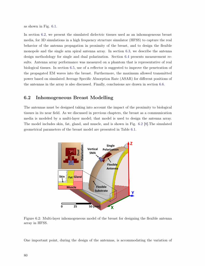
as shown in Fig. 6.1.
In section 6.2, we present the simulated dielectric tissues used as an inhomogeneous breastmedia, for 3D simulations in a high frequency structure simulator (HFSS) to capture the realbehavior of the antenna propagation in proximity of the breast, and to design the flexiblemonopole and the single arm spiral antenna array. In section 6.3, we describe the antennadesign methodology for single and dual polarization. Section 6.4 presents measurement re-sults. Antenna array performance was measured on a phantom that is representative of realbiological tissues. In section 6.5, use of a reflector is suggested to improve the penetration ofthe propagated EM waves into the breast. Furthermore, the maximum allowed transmittedpower based on simulated Average Specific Absorption Rate (ASAR) for different positions ofthe antennas in the array is also discussed. Finally, conclusions are drawn in section 6.6.
6.2 Inhomogeneous Breast Modelling
The antennas must be designed taking into account the impact of the proximity to biologicaltissues in its near field. As we discussed in previous chapters, the breast as a communicationmedia is modeled by a multi-layer model; that model is used to design the antenna array.The model includes skin, fat, gland, and muscle, and is shown in Fig. 6.2 [8].The simulatedgeometrical parameters of the breast model are presented in Table 6.1.
Z
Y
X
Vertical SMA
Flexible Antenna
Flexible Substrate
Skin Fat
Muscle
Gland
0 25 50 (mm)
Single Polarization
Du
al
Po
lari
zati
on
Figure 6.2: Multi-layer inhomogeneous model of the breast for designing the flexible antennaarray in HFSS.
One important point, during the design of the antennas, is accommodating the variation of
80

Table 6.1: Characteristic of TX and RX antennas.
Tissue Thickness(mm) Inner radius(mm) Outer radius(mm) Mass Density (kg/m3)Skin 2 68 70 1010Fat 8 60 68 928
Gland 120 0 60 1035Muscle 8 0 0 1040
breast tissues from person to person. After designing the antenna for the specific thicknessesand the defined electrical properties of the tissues, it should be checked while varying thethicknesses (different size of breasts) and electrical properties (∼20%) to be sure that S11 isstill kept below -10 dB. Details of design are given in the next section.
6.3 Flexible Antenna Array
Planar monopole (single-polarization) and spiral (dual-polarization) antennas on a flexiblesubstrate have the potential to meet the constraints of this application: 1) small footprint, 2)biocompatibility, 3) high bandwidth, and 4) light weight to be placed on the breast comfort-ably.
Our single-polarization and dual-polarization antennas are realized as monopole microstrip andsingle-arm spiral antennas respectively and are covered with a biocompatible material (Kaptonpolyimide). For all antennas, the feed circuit is a coplanar waveguide (CPW) transmissionline having 50-Ω impedance over the 2-4 GHz frequency range.
We use 0.05 mm Kapton polyimide as the biocompatible substrate for the flexible anten-nas. The relative permittivity of Kapton polyimide is 3.5. For both antennas, a superstratelayer identical to their substrate layers covers the metal antenna traces. This superstratelayer completely isolated the antenna from the biological tissues making the antennas fullybiocompatible.
6.3.1 Single- and Dual-Polarization Antennas
There are several UWB single polarization monopole antennas designed for breast cancer ex-isting in the literature [106, 112, 113]. These antennas were designed on inflexible substratesthat are ill adapted to the curvature of the breast. Microwave substrates to be as wearableon the breast should be biocompatible and as flexible and as soft as possible. In [56], thetype of Kapton polyimide substrate used has been reported that has the two aforementionedproperties. Due to the polarization selectivity of breast tissues, we are interested in a designthat covers both X and Y polarizations. Although such a design is more complex, it mayadd information to the collected signal by enabling recording of backscattered signal of two
81
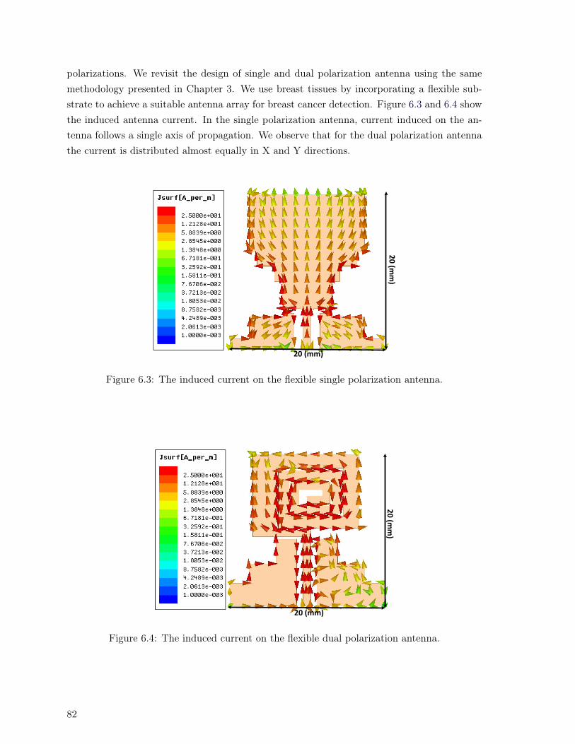
polarizations. We revisit the design of single and dual polarization antenna using the samemethodology presented in Chapter 3. We use breast tissues by incorporating a flexible sub-strate to achieve a suitable antenna array for breast cancer detection. Figure 6.3 and 6.4 showthe induced antenna current. In the single polarization antenna, current induced on the an-tenna follows a single axis of propagation. We observe that for the dual polarization antennathe current is distributed almost equally in X and Y directions.
20 (mm)
20
(mm
)
Figure 6.3: The induced current on the flexible single polarization antenna.
20 (mm)
20
(mm
)
Figure 6.4: The induced current on the flexible dual polarization antenna.
82

6.4 Measurement Results
6.4.1 Measurement Setup
In order to verify our simulation results, we fabricated the arrays on the flexible substrate.Figure 6.5 shows the fabricated arrays which were measured on a phantom. The S11 of differentantenna positions are measured with antenna positions on the array (1-4) shown in Fig. 6.1.The transmission coefficient, S21, of the antenna pairs between antenna 3 in array 1 andantenna 1-4 in array 2 and 3 shown in Fig. 6.1, are also measured. Measurements are madeusing an Agilent PNA-L Network Analyzer N5232A, 300kHz - 20GHz for both single and dualpolarization antennas.
6.4.2 S-parameter Results
Figure 6.6a shows the measured S11 of the single-polarization and Fig. 6.6b shows the mea-sured S11 of the dual-polarization antennas for different positions of the antennas in the arrayas shown in Fig. 6.1. S11 results show good impedance matching (S11 below -10 dB) across the2-4 GHz frequency range for each position. The results demonstrate that the flexible antennais insensitive to bending, and thus is a good candidate for use in the array configuration.
The measured amplitude and phase of S21 (transfer function) between antenna 3 of array 1and antennas 1 to 4 of array 2 and 3 for monopole antenna array (array layouts and antennanumbering shown in Fig. 6.1) are shown in Fig. 6.7a and 6.7b. The measured S21 resultsbetween antenna 3 of array 1 and antennas 1 to 4 of array 2 and 3 for single arm spiralantenna array are plotted in Fig. 6.7c and 6.7d. From the S21 results, we conclude thatantennas that are further apart communicate with higher insertion loss. Additionally, becausethe biological tissues have higher loss in higher frequencies, the S21 results follow this behavior(less insertion loss in lower frequency). From the amplitude and phase behavior of each pair,we observe that the transmitted pulse at one antenna, received by another antenna undergoesa different distortion for each TX/RX antenna pair.
6.5 Improving Penetration of Propagated EM Waves InsideBreast and Maximum Allowed Transmitted Power
In this section, we show that by using a reflector for the antenna arrays, it is possible toimprove penetration of propagated EM waves into the breast from the wearable antennas,which causes an improvement in power efficiency of the links between the antennas, and thusbetter image resolution. We also calculate the maximum power that is allowed to be sentby antennas in different positions in the array shown in Fig. 6.1, with and without use of areflector.
83

2 GHz
-12 dB
4 GHz
-12.4 dB
Phantom
Single
Polarization
Dual
Polarization
(a)
Nipple Location
SMA
Connectors
95 m
m
24 m
m
30 mm
(b)
Figure 6.5: The S-parameter measurement set up a) Antenna array placed on the dielectrictissue-mimicking phantom, and b) Top view of the array, identifying the nipple location.84

(a)
(b)
Figure 6.6: The measured S11 for different positions of the antennas in the array (a) monopoleantenna, and (b) single arm spiral antenna.
6.5.1 Improving Penetration of Propagated EM Waves
Electromagnetic waves are used to transport information through a wireless medium or aguiding structure, from one point to the other. The quantity used to describe the powerassociated with an electromagnetic wave is the time average Poynting vector (average powerdensity) [7]:
Wav(x, y, z) = 1/2 × [E ×H∗] (6.1)
where E and H are the peak values of instantaneous electric-field intensity (V/m) and instan-taneous magnetic-field intensity (A/m), respectively.
The real part of (6.1) is averaged over the propagated power density, and the imaginary partrepresents the reactive (stored) power density associated with the electromagnetic fields. Thereal part is responsible for delivering power from one antenna to another antenna. Figure 6.8shows the real part of the Poynting vector when antenna 4 is propagating in the Z-X planefor monopole and spiral antenna arrays. This figure shows that by using a reflector behindthe antenna arrays, it is possible to improve the penetration of the propagated EM inside thebreast.
85
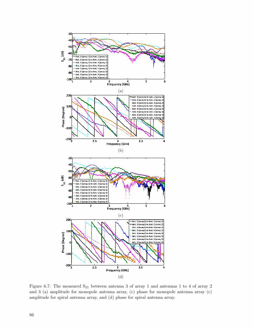
(a)
(b)
(c)
(d)
Figure 6.7: The measured S21 between antenna 3 of array 1 and antennas 1 to 4 of array 2and 3 (a) amplitude for monopole antenna array, (c) phase for monopole antenna array (c)amplitude for spiral antenna array, and (d) phase for spiral antenna array.
86

0 25 50 (mm)0 25 50 (mm) Y
Z
YX
ZActivated Antenna Activated Antenna
X
With Reflector
Without Reflector
X
5.00004.64364.28713.93073.57433.21792.86142.50502.14861.79211.43571.0793.72286.366430.0100
Poynting[W/m^2]
(a)
0 25 50 (mm)0 25 50 (mm) YX
Z
YX
ZActivated Antenna Activated Antenna
Reflector
Skin
Fat
Muscle
Gla
nd1 cm
An
ten
na
X
With Reflector
Without Reflector
(b)
Figure 6.8: The real part of the Poynting vector propagating in the Z-X plane for antenna4: without reflector (left side) and with reflector (right side) for a) monopole and b) spiralantenna arrays; color map applies to all cases.
The reflector should be placed far enough that it does not affect the S11 of the antennas.By placing the reflector further than 1 cm from the antennas, S11 remains unchanged. HFSSresults show that for the spiral antenna using the reflector, the real part of the Poynting vectorin the position of (x = 0, y = 0, and z = 0) improves by a factor of 3.3, and similarly, bya factor of 2.6 for the monopole. This significant penetration of EM waves inside the breastimproves the power efficiency of the link and the ability to detect the presence of a tumor.
6.5.2 Maximum Allowed Transmitted Power by the Antennas
Average Specific Absorption Rate (ASAR) describes the electromagnetic energy that is ab-sorbed in biological tissues and is a critical parameter for assessing the tissue-safety of wirelesscommunications in bio applications. The peak 1-g ASAR spatial distribution versus frequencyis simulated in HFSS for all four positions of the antennas inside the array for the monopoleand spiral antennas, with and without use of a reflector. The ANSI limitations specify amaximum peak 1-g ASAR of 1.6 W/kg [80].
87
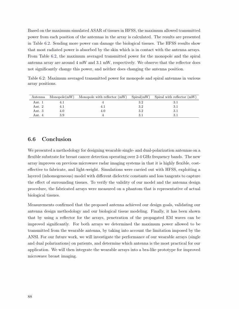
Based on the maximum simulated ASAR of tissues in HFSS, the maximum allowed transmittedpower from each position of the antennas in the array is calculated. The results are presentedin Table 6.2. Sending more power can damage the biological tissues. The HFSS results showthat most radiated power is absorbed by the skin which is in contact with the antenna arrays.From Table 6.2, the maximum averaged transmitted power for the monopole and the spiralantenna array are around 4 mW and 3.1 mW, respectively. We observe that the reflector doesnot significantly change this power, and neither does changing the antenna position.
Table 6.2: Maximum averaged transmitted power for monopole and spiral antennas in variousarray positions.
Antenna Monopole(mW) Monopole with reflector (mW) Spiral(mW) Spiral with reflector (mW)Ant. 1 4.1 4 3.2 3.1Ant. 2 4.1 4.1 3.2 3.1Ant. 3 4.0 4.0 3.2 3.1Ant. 4 3.9 4 3.1 3.1
6.6 Conclusion
We presented a methodology for designing wearable single- and dual-polarization antennas on aflexible substrate for breast cancer detection operating over 2-4 GHz frequency bands. The newarray improves on previous microwave radar imaging systems in that it is highly flexible, cost-effective to fabricate, and light-weight. Simulations were carried out with HFSS, exploiting alayered (inhomogeneous) model with different dielectric constants and loss tangents to capturethe effect of surrounding tissues. To verify the validity of our model and the antenna designprocedure, the fabricated arrays were measured on a phantom that is representative of actualbiological tissues.
Measurements confirmed that the proposed antenna achieved our design goals, validating ourantenna design methodology and our biological tissue modeling. Finally, it has been shownthat by using a reflector for the arrays, penetration of the propagated EM waves can beimproved significantly. For both arrays we determined the maximum power allowed to betransmitted from the wearable antenna, by taking into account the limitation imposed by theANSI. For our future work, we will investigate the performance of our wearable arrays (singleand dual polarizations) on patients, and determine which antenna is the most practical for ourapplication. We will then integrate the wearable arrays into a bra-like prototype for improvedmicrowave breast imaging.
88

Chapter 7
Conclusions and Future Work
The major subject of this thesis was to design a power efficient ultra wideband high speedwireless link for implant-to-air data communications. We investigated step by step of designingthe wireless link from system level design to circuit level design. We have covered biologicaltissues modeling in EM software, designing different types of implantable and wearable anten-nas for human head and breast, a new system level design of an implantable transceiver, andcircuit level design of the new transceiver architecture.
In chapter 2, we utilized a realistic model of the biological channel to inform the design ofantennas for the implanted transmitter and the external receiver to determine the maximumallowable power to 1) respect ANSI guidelines for avoiding tissue damage and 2) respect FCCguidelines on unlicensed transmissions. Antennas placement is examined under two scenarioshaving contrasting power constraints. Performance of the system within the biological tissuesis examined via simulation and experiment.
In chapter 3, we focused on designing single and dual-polarization antennas on rigid or flexiblesubstrate for wireless ultra-wideband brain machine interface. We investigated both flexibleand rigid materials and examined performance trade-offs. The proposed antennas were de-signed to operate in a frequency range of 2–11 GHz covering both the 2.45 GHz (ISM) bandand the 3.1–10.6 GHz UWB band. Several advantages were confirmed for dual polarizationantennas: 1) smaller size, 2) lower sensitivity to angular misalignment, and 3) higher fidelity.
In chapter 4, we proposed a new wireless transceiver architecture for implanted systems thatsimultaneously stimulate neurons and record neural responses. This architecture supportslarge numbers of electrodes (> 500), providing 100 Mb/s for the downlink of stimulationsignals, and Gbps for the uplink neural recordings. The proposed transceiver architectureis a shared ultra-wideband antenna which support both ISM band (down-link) and UWBband(up-link).
In chapter 5,we presented a circuit level design of the proposed transceiver which was presented
89

in chapter 4. Proper isolation (> 20 dB) between the TX and RX path is implemented 1)by shaping the transmitted pulses to fall within the unregulated UWB spectrum (3.1-7 GHz),and 2) by space-efficient filtering (avoiding a circulator or diplexer) of the downlink OOKspectrum in the RX low-noise amplifier. The UWB 3.1-7 GHz transmitter can use eitherOOK or binary phase shift keying (BPSK) modulation schemes. The proposed FDT providesdual band 500 Mbps TX uplink data rate and 100 Mbps RX downlink data rate, and it isfully integrated into standard TSMC 0.18 um CMOS within a total size of 0.8 mm2. The totalmeasured power consumption is 10.4 mW in full duplex mode (5 mW at 100 Mbps for RX,and 5.4 mW at 500 Mbps or 10.8 pJ/bit for TX).
Finally in chapter 6, we designed single and dual-polarization antennas for wireless ultra-wideband breast cancer detection systems using an inhomogeneous multi-layer model of thehuman breast. The proposed antennas are designed to operate in a frequency range of 2–4GHz. Furthermore, two flexible conformal 4×4 ultra-wideband antenna arrays (single anddual polarization) were developed for a radar-based breast cancer detection system. By usinga reflector for the arrays, the penetration of the propagated EM waves from the antennas intothe breast can be improved.
Several possible research projects could exploit material presented in this thesis. The presentedmethodology of designing a wireless data communication link in the presence of biologicaltissues can be applied for other sections of the body or low power miniaturized wearablewireless sensors. A big effort is still needed to work on an external transceiver to communicatein real-time with the implanted transceiver. The data rate of the designed interface systemin this thesis can be increased by using equalization, or potentially using antenna arrayswith multiple-input and multiple-output (MIMO) technique and faster technology like 65nmTSMC. Also, on chip antennas can be used. Dissipated power is the most important issuebecause it increases the temperature of the cortex. For this reason, power consumption of thedesigned circuit needs to be further reduced.
90

Publication List
Journal
J1. H. Bahrami, S.A. Mirbozorgi, L.A. Rusch, and B. Gosselin, “Biological Channel Mod-eling and Implantable UWB Antenna Design for Neural Recording Systems,” IEEETransactions on Biomedical Engineering, vol.62, no.1, pp.88-98, Jan. 2015.
J2. H. Bahrami, S.A. Mirbozorgi, R. Ameli, L.A. Rusch, and B. Gosselin, “Flexible UWBAntennas with Polarization-Diverse Implantable for Neural Recording Systems,” IEEETransactions on Biomedical Circuits and Systems, (Accepted, 2015).
J3. H. Bahrami, S.A. Mirbozorgi, T.A. Nguyen, B. Gosselin, and L.A. Rusch, “System LevelDesign of High-Speed Full-Duplex Transceiver for Neural Recording and StimulatingSystems,” IEEE Transactions on Microwave Theory and Techniques, (Under review,2015).
J4. S.A. Mirbozorgi, H. Bahrami, M. Sawan, L.A. Rusch, and B. Gosselin, “Fully IntegratedCirculator-less Full Duplex Transceiver Circuit Design for Bio-Implant Applications,”IEEE Transactions on Biomedical Circuits and Systems (Under review, 2015).
J5. H. Bahrami, E. Porter, A. Santorelli, B. Gosselin, M. Popovic, and L.A. Rusch, “FlexibleSixteen Antenna Array for Microwave Breast Cancer Detection ,” IEEE Transactionson Biomedical Engineering, (Under review, 2014).
Conference
C1. H. Bahrami, B. Gosselin, and L.A. Rusch, "Design of a miniaturized UWB antenna opti-mized for implantable neural recording systems," New Circuits and Systems Conference(NEWCAS), IEEE 10th International, 2012.
91

C2. H. Bahrami, B. Gosselin, and L.A. Rusch, "Realistic modeling of the biological channelfor the design of implantable wireless UWB communication systems," Engineering inMedicine and Biology Society (EMBC), Annual International Conference of the IEEE,2012.
C3. S.A. Mirbozorgi, H. Bahrami, L.A. Rusch, and B. Gosselin, “A Low-Power 2.4-GHzReceiver for Wireless Implantable Neural Stimulators,” IEEE International Symposiumon Circuits and Systems, ISCAS, Melbourne, Australia, June 2014.
C4. H. Bahrami, S.A. Mirbozorgi, L.A. Rusch, and B. Gosselin, “BER Performance ofImplant-to-Air High-Speed UWBData Communications for Neural Recording Systems,”36th annual Conf. of EMBC, Chicago, USA, August 2014.
C5. M.E. Khaled, H. Bahrami, P. Fortier, B. Gosselin, and L.A. Rusch, "Capacity of UWBwireless channel for neural recording systems," Engineering in Medicine and BiologySociety (EMBC), 36th Annual International Conference of the IEEE, 2014.
C6. H. Bahrami, E. Porter, A. Santorelli, B. Gosselin, M. Popovic, and L.A. Rusch, "Flexiblesixteen monopole antenna array for microwave breast cancer detection," Engineering inMedicine and Biology Society (EMBC), 36th Annual International Conference of theIEEE, 2014.
Book Chapter
1. H. Bahrami, L.A. Rusch and B. Gosselin, Biological channel modeling and implantableUWB antenna design; Handbook of Bioelectronics, Cambridge University Press, (Inprogress, 2015).
92

Bibliography
[1] S. Gabriel and C. Gabriel. The dielectric properties of biological tissues: Iii. parametricmodels for the dielectric spectrum of tissues. Physics in Medicine and Biology, vol.41,no.11, pp.22-71, 1996.
[2] D. Zhou and E. Greenbaum. Implantable Neural Prostheses 2: Techniques and Engi-neering Approaches. Biological and Medical Physics, Biomedical Engineering. Springer,2010.
[3] M. Chae, Z. Yang, M.R. Yuce, H. Linh, and W. Liu. A 128-channel 6 mw wirelessneural recording ic with spike feature extraction and uwb transmitter. Neural Systemsand Rehabilitation Engineering, IEEE Transactions on, vol.17, no.4, pp.312-321, 2009.
[4] K.Y. Yazdandoost. A 2.4 ghz antenna for medical implanted communications. pp.1775-1778, 2009.
[5] T.F. Chien, H.C. Yang, C.M. Cheng, and C.H. Luo. Develop cpw-fed monopole broad-band implantable antennas on the high dielectric constant ceramic substrates. Microwaveand Optical Technology Letters, vol.52, no.9, pp.2136-2139, 2010.
[6] J. Kim and Y. Rahmat-Samii. Implanted antennas inside a human body: simulations,designs, and characterizations. Microwave Theory and Techniques, IEEE Transactionson, vol.52, no.8, pp.1934-1943, 2004.
[7] C.A. Balanis. Advanced Engineering Electromagnetics. Course Smart Series. Wiley,2012.
[8] P. Ghanbari and M. Hajj. Finite element analysis of tissue electropermeability throughthe application of electric pulses. J Bioengineer and Biomedical Sci, vol.3, pp.2318-2326,2013.
[9] D. Valderas. Ultrawideband Antennas: Design and Applications. Imperial College Press,2011.
93

[10] U.M. Jow and M. Ghovanloo. Optimization of data coils in a multiband wireless linkfor neuroprosthetic implantable devices. Biomedical Circuits and Systems, IEEE Trans-actions on, vol.4, no.5, pp.301-310, 2010.
[11] B. Sklar. Digital communications: fundamentals and applications. Prentice Hall Com-munications Engineering and Emerging Technologies Series. Prentice-Hall PTR, 2001.
[12] M. Ojaroudi, C. Ghobadi, and J. Nourinia. Small square monopole antenna with in-verted t-shaped notch in the ground plane for uwb application. Antennas and WirelessPropagation Letters, IEEE, vol.8, pp.728-731, 2009.
[13] Reza Zaker and A. Abdipour. A very compact ultrawideband printed omnidirectionalmonopole antenna. Antennas and Wireless Propagation Letters, IEEE, vol.9, pp.471-473, 2010.
[14] H. Zamani and P. Mohseni. A high-speed circuit architecture for ir-uwb transmission offast-scan cyclic voltammetry in 0.35 um cmos. pp.1561-1564, 2010.
[15] M. Mark, T. Bjorninen, Y.D. Chen, S. Venkatraman, L. Ukkonen, L. Sydanheimo, J.M.Carmena, and J.M. Rabaey. Wireless channel characterization for mm-size neural im-plants. Engineering in Medicine and Biology Society (EMBC), 2010 Annual Interna-tional Conference of the IEEE, pp.1565-1568, 2010.
[16] E. Pancera and W. Wiesbeck. Fidelity based optimization of uwb antenna-radiation formedical applications. Antennas and Propagation (APSURSI), 2011 IEEE InternationalSymposium on, pp.2411-2414, 2011.
[17] M. Leib, M. Frei, D. Sailer, and W. Menzel. Design and characterization of a uwb slotantenna optimized for radiation in human tissue. Ultra-Wideband, 2009. ICUWB 2009.IEEE International Conference on, pp.159-163, 2009.
[18] T. Dissanayake, M.R. Yuce, and Chee Ho. Design and evaluation of a compact antennafor implant-to-air uwb communication. Antennas and Wireless Propagation Letters,IEEE, vol.8, pp.153-156, 2009.
[19] Qiong Wang, K. Wolf, and D. Plettemeier. An uwb capsule endoscope antenna designfor biomedical communications. pp.1-6, 2010.
[20] J.C. Wang, E.G. Lim, Z. Wang, Y. Huang, T. Tillo, M. Zhang, and R. Alrawashdeh.Uwb planar antennas for wireless capsule endoscopy. pp.340-343, 2013.
[21] A. Drossos, V. Santomaa, and N. Kuster. The dependence of electromagnetic energyabsorption upon human head tissue composition in the frequency range of 300-3000 mhz.Microwave Theory and Techniques, IEEE Transactions on, vol.48, no.11, pp.1988-1995,2000.
94
[22] C.A. Balanis. ANTENNA THEORY: ANALYSIS AND DESIGN, 2ND ED. Wiley IndiaPvt. Limited, 2007.
[23] Y.S. Chen, S.Y. Chen, and H.J. Li. Analysis of antenna coupling in near-field com-munication systems. Antennas and Propagation, IEEE Transactions on, vol.58, no.10,pp.3327-3335, 2010.
[24] F. Merli, B. Fuchs, J.R. Mosig, and A.K. Skrivervik. The effect of insulating layers onthe performance of implanted antennas. Antennas and Propagation, IEEE Transactionson, vol.59, no.1, pp.21-31, 2011.
[25] H. Bahrami, B. Gosselin, and L.A. Rusch. Design of a miniaturized uwb antenna opti-mized for implantable neural recording systems. pp.309-312, 2012.
[26] H. Bahrami, B. Gosselin, and L.A. Rusch. Realistic modeling of the biological channelfor the design of implantable wireless uwb communication systems. pp.6015-6018, 2012.
[27] G. Chaudhary, Yongchae Jeong, and Jongsik Lim. Microstrip line negative group delayfilters for microwave circuits. Microwave Theory and Techniques, IEEE Transactionson, vol.62, no.2, pp.234-243, 2014.
[28] A.R. Eskandari, L. Mohammady, and B. Eliasi. A novel method for analyzing andpredicting of group delay variations in wideband transmission lines. pp.298-301, 2007.
[29] Ian Oppermann. The role of uwb in 4g. Wirel. Pers. Commun., vol.29, no.2, pp.121-133,2004.
[30] Ieee standard for safety levels with respect to human exposure to radio frequency elec-tromagnetic fields, 3 khz to 300 ghz. IEEE Std C95.1-2005 (Revision of IEEE StdC95.1-1991), pp.230-238, 2006.
[31] A. Peyman, C. Gabriel, E.H. Grant, G. Vermeeren, and L. Martens. Variation of thedielectric properties of tissues with age: the effect on the values of sar in children when ex-posed to walkie–talkie devices. Physics in Medicine and Biology, vol.55, no.17, pp.5240-5249, 2010.
[32] A. Peyman, S.J. Holden, S. Watts, R. Perrott, and C. Gabriel. Dielectric properties ofporcine cerebrospinal tissues at microwave frequencies: in vivo , in vitro and systematicvariation with age. Physics in Medicine and Biology, vol.52, no.8, pp.22-29, 2007.
[33] M.A. Stuchly, A. Kraszewski, S.S. Stuchly, and A.M. Smith. Dielectric properties ofanimal tissues in vivo at radio and microwave frequencies: comparison between species.Physics in Medicine and Biology, vol.27, no.7, pp.920-927, 1982.
95

[34] A. Peyman, A.A. Rezazadeh, and C. Gabriel. Changes in the dielectric properties of rattissue as a function of age at microwave frequencies. Physics in Medicine and Biology,vol.46, no.6, pp.16-17, 2001.
[35] C. Gabriel and A. Peyman. Dielectric measurement: error analysis and assessment ofuncertainty. Physics in Medicine and Biology, vol.51, no.23, pp.6025-6033, 2006.
[36] M.R. Yuce and T. Dissanayake. Easy-to-swallow wireless telemetry. Microwave Maga-zine, IEEE, vol.13, no.6, pp.90-101, 2012.
[37] M.R. Yuce, T. Dissanayake, and H.C. Keong. Wireless telemetry for electronic pilltechnology. pp.1433-1438, 2009.
[38] Y. Chen, J. Teo, J.C.Y. Lai, E. Gunawan, K.S. Low, C.B. Soh, and P.B. Rapajic. Coop-erative communications in ultra-wideband wireless body area networks: Channel mod-eling and system diversity analysis. Selected Areas in Communications, IEEE Journalon, vol.27, no.1, pp.5-16, 2009.
[39] Jingjing Shi and Jianqing Wang. Channel characterization and diversity feasibility forin-body to on-body communication using low-band uwb signals. pp.1-4, 2010.
[40] K. Sayrafian-Pour, Wen-Bin Yang, J. Hagedorn, J. Terrill, and K.Y. Yazdandoost. Astatistical path loss model for medical implant communication channels. pp.2995-2999,2009.
[41] A. Khaleghi, R. Cha´vez-Santiago, and I. Balasingham. Ultra-wideband statistical prop-agation channel model for implant sensors in the human chest. Microwaves, AntennasPropagation, IET, vol.5, no.15, pp.1805-1812, 2011.
[42] R. Chavez-Santiago, K. Sayrafian-Pour, A. Khaleghi, K. Takizawa, J. Wang, I. Balas-ingham, and H.B. Li. Propagation models for ieee 802.15.6 standardization of implantcommunication in body area networks. Communications Magazine, IEEE, vol.51, no.8,pp.80-87, 2004.
[43] D. Anzai, K. Katsu, R. Chavez-Santiago, Q. Wang, D. Plettemeier, J. Wang, and I. Bal-asingham. Experimental evaluation of implant uwb-ir transmission with living animalfor body area networks. Microwave Theory and Techniques, IEEE Transactions on,vol.62, no.1, pp.183-192, 2014.
[44] R. Chavez-Santiago, I. Balasingham, J. Bergsland, W. Zahid, K. Takizawa, R. Miura,and H.B. Li. Experimental implant communication of high data rate video using anultra wideband radio link. pp.5175-5178, 2013.
96

[45] H. Bahrami, S.A. Mirbozorgi, L.A. Rusch, and B. Gosselin. Ber performance of implant-to-air high-speed uwb data communications for neural recording systems. vol.29, no.2,pp.3961-3964, 2014.
[46] M. El Khaled, H. Bahrami, P. Fortier, B. Gosselin, and L.A. Rusch. Capacity of uwbwireless channel for neural recording systems. pp.3965-3968, 2014.
[47] M.L. Scarpello, D. Kurup, H. Rogier, D. Vande Ginste, F. Axisa, J. Vanfleteren,W. Joseph, L. Martens, and G. Vermeeren. Design of an implantable slot dipole con-formal flexible antenna for biomedical applications. Antennas and Propagation, IEEETransactions on, vol.59, no.10, pp.3556-3564, 2011.
[48] R. Alrawashdeh, Y. Huang, and P. Cao. Flexible meandered loop antenna for implantsin medradio and ism bands. Electronics Letters, vol.49, no.24, pp.1515-1517, 2013.
[49] Z. Wang, L. Zhang, D. Psychoudakis, and J.L. Volakis. Flexible textile antennas forbody-worn communication. pp.205-208, 2012.
[50] C. Kim, J. K. Kim, K.T. Kim, and Y.K. Yoon. Micromachined wearable/foldable su-per wideband (swa) monopole antenna based on a flexible liquid crystal polymer (lcp)substrate toward imaging/sensing/health monitoring systems. pp.1926-1932, 2013.
[51] H. Bahrami, S.A. Mirbozorgi, L.A. Rusch, and B. Gosselin. Biological channel mod-eling and implantable uwb antenna design for neural recording systems. BiomedicalEngineering, IEEE Transactions on, vol.62, no.1, pp.88-98, 2015.
[52] H.K. Yoon, J.A. Park A, Y.J. Yoon, and C.H. Lee. A cpw-fed polarization diversityantenna for uwb systems. pp.1-4, 2008.
[53] H.K. Yoon, Y.J. Yoon, H. Kim, and C.H. Lee. Flexible ultra-wideband polarisationdiversity antenna with band-notch function. Microwaves, Antennas Propagation, IET,vol.5, no.12, pp.1463-1470, 2011.
[54] L. Vallozzi, P. Van Torre, C. Hertleer, H. Rogier, M. Moeneclaey, and J. Verhaev-ert. Wireless communication for firefighters using dual-polarized textile antennas inte-grated in their garment. Antennas and Propagation, IEEE Transactions on, vol.58, no.4,pp.1357-1368, 2010.
[55] H.R. Khaleel, H.M. Al-Rizzo, and D.G. Rucker. Compact polyimide-based antennas forflexible displays. Display Technology, Journal of, vol.8, no.2, pp.91-97, 2012.
[56] H.R. Khaleel, H.M. Al-Rizzo, D.G. Rucker, and S. Mohan. A compact polyimide-baseduwb antenna for flexible electronics. Antennas and Wireless Propagation Letters, IEEE,vol.11, pp.564-567, 2012.
97
[57] W. El Hajj, C. Person, and J. Wiart. A miniaturized rectangular-spiral bi-band coplanarantenna for off-body communications. pp.3262-3265, 2013.
[58] S.H. Lee, J. Lee, J.Y. Young, S. Park, C. Cheon, K. Kim, and S. Nam. A widebandspiral antenna for ingestible capsule endoscope systems: Experimental results in a hu-man phantom and a pig. Biomedical Engineering, IEEE Transactions on, vol.58, no.6,pp.1734-1741, 2011.
[59] T.S.P. See and Z.N. Chen. Experimental characterization of uwb antennas for on-body communications. Antennas and Propagation, IEEE Transactions on, vol.57, no.4,pp.866-874, 2009.
[60] K. Rambabu, A.E.C. Tan, K.K.M. Chan, and M.Y.W. Chia. Estimation of antennaeffect on ultra-wideband pulse shape in transmission and reception. ElectromagneticCompatibility, IEEE Transactions on, vol.51, no.3, pp.604-610, 2009.
[61] A.H. Mohammadian, A. Rajkotia, and S.S. Soliman. Characterization of uwb transmit-receive antenna system. pp.157-161, 2003.
[62] G. Simard, M. Sawan, and D. Massicotte. Novel coils topology intended for biomedicalimplants with multiple carrier inductive link. pp.537-540, 2009.
[63] G. Simard, M. Sawan, and D. Massicotte. High-speed oqpsk and efficient power transferthrough inductive link for biomedical implants. Biomedical Circuits and Systems, IEEETransactions on, vol.4, no.3, pp.192-200, 2010.
[64] S.A. Mirbozorgi, H. Bahrami, L.A. Rusch, and B. Gosselin. A low-power 2.4-ghz receiverfor wireless implantable neural stimulators. pp.1082-1085, 2014.
[65] B. Gosselin, A.E. Ayoub, J.F. Roy, M. Sawan, F. Lepore, A. Chaudhuri, and D. Gui-tton. A mixed-signal multichip neural recording interface with bandwidth reduction.Biomedical Circuits and Systems, IEEE Transactions on, vol.3, no.3, pp.129-141, 2009.
[66] Y. Gao, Y. Zheng, S. Diao, W.D. Toh, C.W. Ang, M. Je, and C.H. Heng. Low-powerultrawideband wireless telemetry transceiver for medical sensor applications. BiomedicalEngineering, IEEE Transactions on, vol.58, no.3, pp.768-772, 2011.
[67] H. Miranda and T.H. Meng. A programmable pulse uwb transmitter with 34multichannelneuro-recording systems. pp.1-4, 2010.
[68] S.C. Shin, J.Y. Huang, K.Y. Lin, and H. Wang. A 1.5-9.6 ghz monolithic active quasi-circulator in 0.18 um cmos technology. Microwave and Wireless Components Letters,IEEE, vol.18, no.12, pp.797-799, 2008.
98
[69] Z. El-Khatib, L. MacEachern, and S.A. Mahmoud. A fully-integrated linearized cmosbidirectional distributed amplifier as uwb active circulator. pp.106-109, 2008.
[70] S. He, N. Akel, and C.E. Saavedra. Active quasi-circulator with high port-to-port isola-tion and small area. Electronics Letters, vol.48, no.14, pp.848-850, 2012.
[71] H. Morkner, M. Karakucuk, G. Carr, and S. Espino. A full duplex front end module forwifi 802.11.n applications. pp.162-165, 2008.
[72] T.Y. Yun, C. Wang, P. Zepeda, C.T. Rodenbeck, M.R. Coutant, M. Li, and K. Chang.A 10- to 21-ghz, low-cost, multifrequency, and full-duplex phased-array antenna system.Antennas and Propagation, IEEE Transactions on, vol.50, no.5, pp.641-650, 2002.
[73] K. Oh, S. Sankaran, H.T. Wu, J.J. Lin, M. Hwang, and K.O. Kenneth. Full-duplexcrystalless cmos transceiver with an on-chip antenna for wireless communication in ahybrid engine controller board. Solid-State Circuits, IEEE Journal of, vol.48, no.6,pp.1327-1342, 2013.
[74] X. Zhang, M. Elgamel, and M.A. Bayoumi. Gaussian pulse approximation using stan-dard cmos and its application for sub-ghz uwb impulse radio. International Journal ofCircuit Theory and Applications, vol.38, no.4, pp.383-407, 2010.
[75] D.D. Wentzloff and A.P. Chandrakasan. Gaussian pulse generators for subbanded ultra-wideband transmitters. Microwave Theory and Techniques, IEEE Transactions on,vol.54, no.4, pp.1647-1655, 2006.
[76] M. Demirkan and R.R. Spencer. A pulse-based ultra-wideband transmitter in 90-nmcmos for wpans. Solid-State Circuits, IEEE Journal of, vol.43, no.12, pp.2820-2828,2008.
[77] Y. Zhu, J.D. Zuegel, J.R. Marciante, and H. Wu. Distributed waveform generator:A new circuit technique for ultra-wideband pulse generation, shaping and modulation.Solid-State Circuits, IEEE Journal of, vol.44, no.3, pp.808-823, 2009.
[78] L. Zhou, Z. Chen, C.C. Wang, F. Tzeng, V. Jain, and P. Heydari. A 2-gb/s 130-nm cmosrf-correlation-based ir-uwb transceiver front-end. Microwave Theory and Techniques,IEEE Transactions on, vol.59, no.4, pp.1117-1130, 2011.
[79] H. Kim and Y. Joo. Fifth-derivative gaussian pulse generator for uwb system. pp.671-674, 2005.
[80] Ieee standard for safety levels with respect to human exposure to radio frequency elec-tromagnetic fields, 3 khz to 300 ghz. IEEE Standard for Safety Levels with Respect toHuman Exposure to Radio Frequency Electromagnetic Fields, 3 kHz to 300 GHz.
99

[81] R.R. Harrison, R.J. Kier, C.A. Chestek, V. Gilja, P. Nuyujukian, S. Ryu, B. Greger,F. Solzbacher, and K.V. Shenoy. Wireless neural recording with single low-power inte-grated circuit. Neural Systems and Rehabilitation Engineering, IEEE Transactions on,vol.17, no.4, pp.322-329, 2009.
[82] A. Berenyi, Z. Somogyvari, A.J. Nagy, L. Roux, J.D. Long, S. Fujisawa, E. Stark,A. Leonardo, T.D. Harris, and G. Buzsaki. Large-scale, high-density (up to 512 channels)recording of local circuits in behaving animals. Journal of Neurophysiology, pp.1522-1598, 2013.
[83] K. Chen, Z. Yang, L. Hoang, J. Weiland, M. Humayun, and W. Liu. An integrated256-channel epiretinal prosthesis. Solid-State Circuits, IEEE Journal of, vol.45, no.9,pp.1946-1956, 2010.
[84] A.G. Rouse, S.R. Stanslaski, P. Cong, R.M. Jensen, P. Afshar, D. Ullestad, R. Gupta,G.F. Molnar, D.W. Moran, and T.J. Denison. A chronic generalized bi-directionalbrain–machine interface. Journal of Neural Engineering, vol.8, no.3, pp.3556-3564, 2011,2011.
[85] M. Ghovanloo and K. Najafi. A wireless implantable multichannel microstimulatingsystem-on-a-chip with modular architecture. Neural Systems and Rehabilitation Engi-neering, IEEE Transactions on, vol.15, no.3, pp.449-457, 2007.
[86] D. Daoud, M. Ghorbel, A. Ben Hamida, and J. Tomas. A wireless data and powerrecovery for biomedical microsystems implants. pp.1-5, 2011.
[87] N.P. Cook, L. Sieber, and H. Widmer. High efficiency and power transfer in wirelesspower magnetic resonators. 2010.
[88] M. Kiani, U.M. Jow, and M. Ghovanloo. Design and optimization of a 3-coil inductivelink for efficient wireless power transmission. Biomedical Circuits and Systems, IEEETransactions on, vol.5, no.6, pp.579-591, 2011.
[89] A.K. RamRakhyani and G. Lazzi. On the design of efficient multi-coil telemetry systemfor biomedical implants. Biomedical Circuits and Systems, IEEE Transactions on, vol.7,no.1, pp.11-23, 2013.
[90] G. Yilmaz, O. Atasoy, and C. Dehollain. Wireless energy and data transfer for in-vivoepileptic focus localization. Sensors Journal, IEEE, vol.13, no.11, pp.4172-4179, 2013.
[91] F. Yazicioglu, C.M. Lopez, S. Mitra, B. Raducanu, S. Musa, and F. Kloosterman. Ultra-high-density in-vivo neural probes. pp.2032-2035, 2014.
[92] A. Berenyi, Z. Somogyvari, A.J. Nagy, L. Roux, J.D. Long, S. Fujisawa, E. Stark,A. Leonardo, T.D. Harris, and G. Buzsaki. Large-scale, high-density (up to 512 channels)
100

recording of local circuits in behaving animals. Journal of Neurophysiology, pp.1522-1598, 2013.
[93] T. Wada, R. Nakajima, H. Obiya, T. Ogami, M. Koshino, M. Kawashima, and N. Naka-jima. A miniaturized broadband lumped element circulator for reconfigurable front-endsystem. pp.1-3, 2014.
[94] O. Novak, W. Wu, and C. Charles. Wireless ultra-wide-band data link for biomedicalimplants. pp.352-355, 2009.
[95] M. Chae, W. Liu, Z. Yang, T. Chen, J. Kim, M. Sivaprakasam, and M. Yuce. A128-channel 6mw wireless neural recording ic with on-the-fly spike sorting and uwbtansmitter. pp.146-603, 2008.
[96] W. Wu, O. Novak, C.T. Charles, and X. Fan. A low-power 3.1-5ghz ultra-wideband lownoise amplifier utilizing miller effect. pp.255-259, 2009.
[97] M.T. Reiha and J.R. Long. A 1.2 v reactive-feedback 3.1 ndash;10.6 ghz low-noiseamplifier in 0.13 um cmos. Solid-State Circuits, IEEE Journal of, vol.42, no.5, pp.1023-1033, 2007.
[98] H.H. Hsieh, J.H. Wang, and L.H. Lu. Gain-enhancement techniques for cmos foldedcascode lnas at low-voltage operations. Microwave Theory and Techniques, IEEE Trans-actions on, vol.56, no.8, pp.1807-1816, 2008.
[99] D.A. Guimaraes. Digital Transmission: A Simulation-Aided Introduction with Vis-Sim/Comm. Signals and Communication Technology. Springer Berlin Heidelberg, 2010.
[100] M. Yin, D.A. Borton, J. Aceros, W.R. Patterson, and A.V. Nurmikko. A 100-channelhermetically sealed implantable device for chronic wireless neurosensing applications.Biomedical Circuits and Systems, IEEE Transactions on, vol.7, no.2, pp.115-128, 2013.
[101] E.C. Fear, S.C. Hagness, P.M. Meaney, M. Okoniewski, and M.A. Stuchly. Enhancingbreast tumor detection with near-field imaging. Microwave Magazine, IEEE, vol.3, no.1,pp.48-56, 2002.
[102] S.K. Davis, B.D. Van Veen, S.C. Hagness, and F. Kelcz. Breast tumor characterizationbased on ultrawideband microwave backscatter. Biomedical Engineering, IEEE Trans-actions on, vol.55, no.1, pp.237-246, 2008.
[103] S.P. Poplack, T.D. Tosteson, W.A. Wells, B.W. Pogue, P.M. Meaney, A. Hartov, C.A.Kogel, S.K. Soho, J.J. Gibson, and K.D. Paulsen. Electromagnetic breast imaging:Results of a pilot study in women with abnormal mammograms. Radiology, vol.243,no.2, pp.350-359, 2007.
101

[104] D. Gibbins, M. Klemm, I.J. Craddock, J.A. Leendertz, A. Preece, and R. Benjamin. Acomparison of a wide-slot and a stacked patch antenna for the purpose of breast cancerdetection. Antennas and Propagation, IEEE Transactions on, vol.58, no.3, pp.665-674,2010.
[105] M. Klemm, J.A. Leendertz, D. Gibbins, I.J. Craddock, A. Preece, and R. Benjamin. Mi-crowave radar-based differential breast cancer imaging: Imaging in homogeneous breastphantoms and low contrast scenarios. Antennas and Propagation, IEEE Transactionson, vol.58, no.7, pp.2337-2344, 2010.
[106] T. Sugitani, S. Kubota, A. Toya, X. Xiao, and T. Kikkawa. A compact 4 × 4 planaruwb antenna array for 3-d breast cancer detection. Antennas and Wireless PropagationLetters, IEEE, vol.12, pp.733-736, 2013.
[107] A.M.A. Shaheen and K.M. Quboa. Modeling and optimizing ultra wideband antennasfor microwave breast cancer detection. pp.1-6, 2012.
[108] X. Li, S.C. Hagness, M.K. Choi, and D.W. Van Der Weide. Numerical and experimentalinvestigation of an ultrawideband ridged pyramidal horn antenna with curved launchingplane for pulse radiation. Antennas and Wireless Propagation Letters, IEEE, vol.2, no.1,pp.259-262, 2003.
[109] Y. Wang, A.E. Fathy, and M.R. Mahfouz. Novel compact tapered microstrip slot antennafor microwave breast imaging. pp.2119-2122, 2011.
[110] L. Wang and B. Huang. Design of ultra-wideband mimo antenna for breast tumordetection. pp.2119-2122, 2012.
[111] A. Eesuola, Y. Chen, and G.Y. Tian. Novel ultra-wideband directional antennas formicrowave breast cancer detection. pp.90-93, 2011.
[112] G. Chavka and M. Garbaruk. Design of planar monopole pulse antenna for ultra-wideband radiocommunication systems. pp.129-132, 2007.
[113] S. Latif, D. Flores-Tapia, S. Pistorius, and L. Shafai. A planar ultrawideband ellipticalmonopole antenna with reflector for breast microwave imaging. Microwave and OpticalTechnology Letters, vol.56, no.4, pp.808-813, 2014.
[114] E. Porter, E. Kirshin, A. Santorelli, M. Coates, and M. Popovic. Time-domain multi-static radar system for microwave breast screening. Antennas and Wireless PropagationLetters, IEEE, vol.12, pp.229-232, 2013.
102