High Performance PEM Electrolyzer for Cost-effective...
9
10/5/2017 1 High Performance PEM Electrolyzer for Cost-effective Grid Balancing Applications www.hpem2gas.eu This project has received funding from the Fuel Cells and Hydrogen 2 Joint Undertaking under grant agreement No 700008. This Joint Undertaking receives support from the European Union’s Horizon 2020 research and innovation programme and Hydrogen Europe and N.ERGHY 7 th IEA ANNEX 30 Electrolysis Workshop at 3M, St. Paul USA 10-Oct-2017 Laila Grahl-Madsen (EWII Fuel Cells A/S) Project Coordinator: Dr. Antonino Salvatore Arico (CNR-ITAE) Exploitation Manager: Graham Robson (ITM Power plc) Project Manager: Dr. Anna Molinari (Uniresearch) Duration: 36 months Start date: April 2016 Total budget: 2.65 M€ EC Funding: 2.5 M€ EC Contract number: 700008
Transcript of High Performance PEM Electrolyzer for Cost-effective...

10/5/2017
1
High Performance PEM Electrolyzer for Cost-effective Grid Balancing Applications
www.hpem2gas.eu
This project has received funding from the Fuel Cells and Hydrogen 2Joint Undertaking under grant agreement No 700008. This JointUndertaking receives support from the European Union’s Horizon 2020research and innovation programme and Hydrogen Europe and N.ERGHY
7th IEA ANNEX 30 Electrolysis Workshop at 3M, St. Paul USA
10-Oct-2017
Laila Grahl-Madsen (EWII Fuel Cells A/S)
Project Coordinator: Dr. Antonino Salvatore Arico (CNR-ITAE)
Exploitation Manager: Graham Robson (ITM Power plc)
Project Manager: Dr. Anna Molinari (Uniresearch)
Duration: 36 monthsStart date: April 2016Total budget: 2.65 M€EC Funding: 2.5 M€EC Contract number: 700008
10/5/2017
2
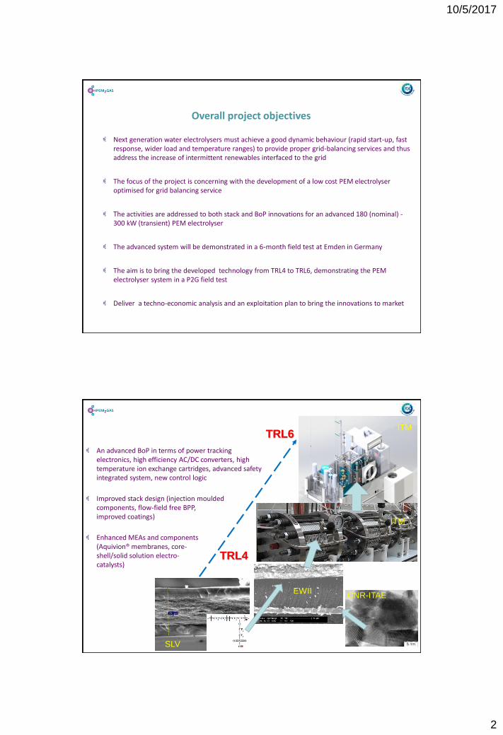
Overall project objectives
Next generation water electrolysers must achieve a good dynamic behaviour (rapid start-up, fast response, wider load and temperature ranges) to provide proper grid-balancing services and thus address the increase of intermittent renewables interfaced to the grid
The focus of the project is concerning with the development of a low cost PEM electrolyser optimised for grid balancing service
The activities are addressed to both stack and BoP innovations for an advanced 180 (nominal) -300 kW (transient) PEM electrolyser
The advanced system will be demonstrated in a 6-month field test at Emden in Germany
The aim is to bring the developed technology from TRL4 to TRL6, demonstrating the PEM electrolyser system in a P2G field test
Deliver a techno-economic analysis and an exploitation plan to bring the innovations to market
An advanced BoP in terms of power tracking electronics, high efficiency AC/DC converters, high temperature ion exchange cartridges, advanced safety integrated system, new control logic
Improved stack design (injection moulded components, flow-field free BPP, improved coatings)
Enhanced MEAs and components (Aquivion® membranes, core-shell/solid solution electro-catalysts)
TRL4
TRL6
SLV
CNR-ITAE
ITM
ITM
EWII
10/5/2017
3
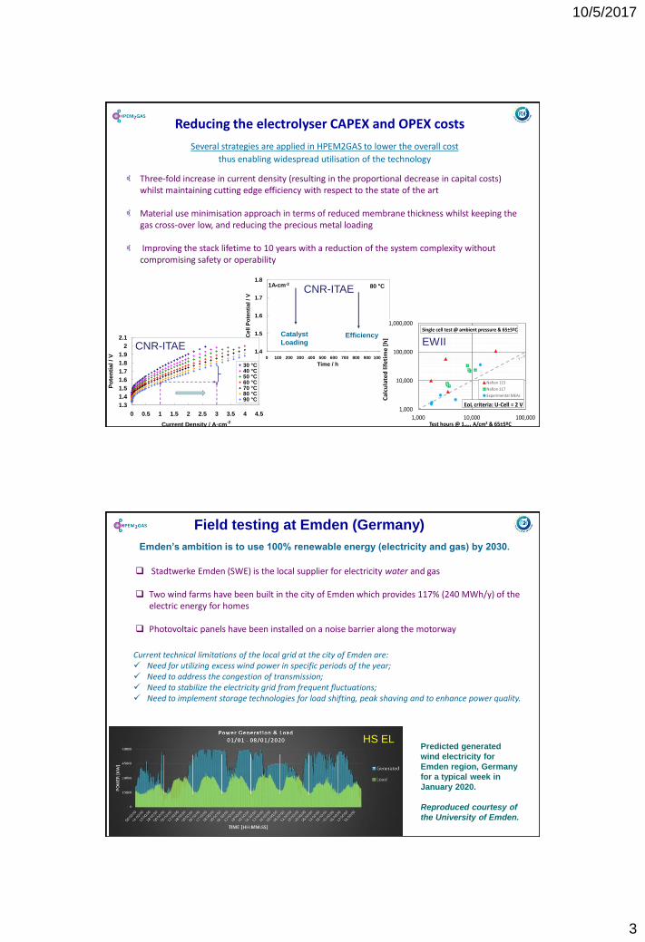
Several strategies are applied in HPEM2GAS to lower the overall cost
thus enabling widespread utilisation of the technology
Three-fold increase in current density (resulting in the proportional decrease in capital costs) whilst maintaining cutting edge efficiency with respect to the state of the art
Material use minimisation approach in terms of reduced membrane thickness whilst keeping the gas cross-over low, and reducing the precious metal loading
Improving the stack lifetime to 10 years with a reduction of the system complexity without compromising safety or operability
Reducing the electrolyser CAPEX and OPEX costs
1.4
1.5
1.6
1.7
1.8
0 100 200 300 400 500 600 700 800 900 1000 1100
Time / h
Ce
ll P
ote
nti
al / V
1Acm-280 C
Catalyst
LoadingEfficiency
1.3
1.4
1.5
1.6
1.7
1.8
1.9
2
2.1
0 0.5 1 1.5 2 2.5 3 3.5 4 4.5
Current Density / A·cm-2
Po
ten
tia
l / V
30 °C40 °C50 °C60 °C70 °C80 °C90 °C
1,000
10,000
100,000
1,000,000
1,000 10,000 100,000
Ca
lcu
late
d l
ife
tim
e [
h]
Test hours @ 1.0±1 A/cm2 & 65±5ºC
Nafion 115
Nafion 117
Experimental MEAs
Single cell test @ ambient pressure & 65±5ºC
EoL criteria: U-Cell = 2 V
EWIICNR-ITAE
CNR-ITAE
Emden’s ambition is to use 100% renewable energy (electricity and gas) by 2030.
Stadtwerke Emden (SWE) is the local supplier for electricity water and gas
Two wind farms have been built in the city of Emden which provides 117% (240 MWh/y) of the electric energy for homes
Photovoltaic panels have been installed on a noise barrier along the motorway
Field testing at Emden (Germany)
Predicted generated
wind electricity for
Emden region, Germany
for a typical week in
January 2020.
Reproduced courtesy of
the University of Emden.
HS EL
Current technical limitations of the local grid at the city of Emden are: Need for utilizing excess wind power in specific periods of the year; Need to address the congestion of transmission; Need to stabilize the electricity grid from frequent fluctuations; Need to implement storage technologies for load shifting, peak shaving and to enhance power quality.

10/5/2017
4
Field testing in Germany
From Jan-2016 and onwards, subsidies for renewable electricity in Germany will decrease to 0 € if the spot market price for wind power is negative for 6 consecutive hourshttps://www.wind-energie.de/sites/default/files/download/publication/zukuenftige-auswirkungen-der-sechs-stunden-regelung-gemaess-ss-24-eeg-2014/2014-12-11_bwe_sechsstunden-regelung_energybrainpool.pdf
Average excess power produced by SWE on a weekly basis

10/5/2017
5
Excess power as years’ duration lineAbout 18 month is the length of the evaluation period
Over the observation period of 13,176 hours the electrolyzer will be in operation in 3,529 hours since this is the time where excess power is available
http://www.hpem2gas.eu
Power to electrolyzer as year’s duration line
Due to the high surplus capacities, it is to be expected that the electrolyzer will be operated at full load during periods of excess current, otherwise it will be shut down.
10/5/2017
6
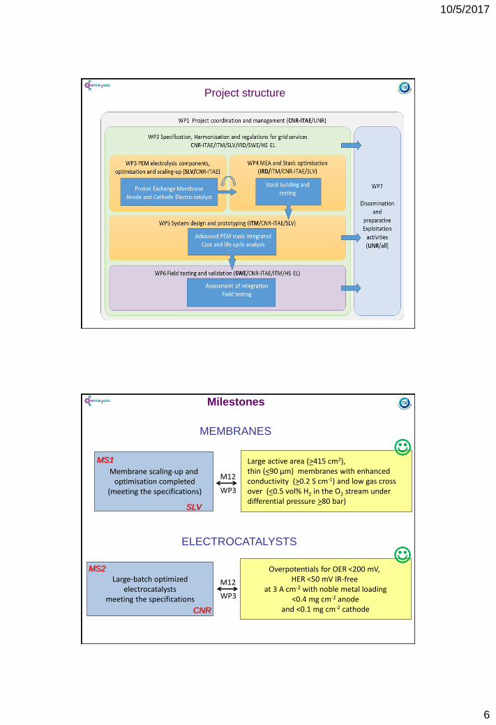
Project structure
Milestones
Membrane scaling-up andoptimisation completed
(meeting the specifications)
MEMBRANES
Large-batch optimizedelectrocatalysts
meeting the specifications
Overpotentials for OER <200 mV, HER <50 mV IR-free
at 3 A cm-2 with noble metal loading<0.4 mg cm-2 anode
and <0.1 mg cm-2 cathode
Large active area (>415 cm2), thin (<90 µm) membranes with enhanced conductivity (>0.2 S cm-1) and low gas cross over (<0.5 vol% H2 in the O2 stream under differential pressure >80 bar)
ELECTROCATALYSTS
M12
M12
WP3
WP3
SLV
CNR
MS1
MS2

10/5/2017
7
Milestones
Optimised large area MEAsmeeting the specifications
Membrane-electrode Assembly (MEAs)
75 cells PEM electrolysis
stack meeting the specifications
Stack prototype consisting of 75 cellswith > 415 cm2 active area, operating at a current density ≥ 3 A cm-2
with an average cell potential < 1.8 V (nominal)and degradation <5 µV/h/cell in a 1000 h test.
Performance of 3 A cm-2 at UCell<1.8 V undernominal operation and up to 4.5 A cm-2 under transient operation (UCell<2 V). Total noble metal loading per MEA <0.5 mg cm-2
Stack
M18
M28
WP4
WP4
PEM electrolysis technology validated at 180 kW
system level
System
Electrolysis system with nominal hydrogen production capacity > 80 kg H2/day, efficiencybetter than 82% HHV H2 and energy consumption lower than 48 kWh/kg H2.
M30
WP5
EWII
ITM
ITM
MS3
MS4
MS5
www.hpem2gas.eu
http://hpem2gas.eu/download/public_reports/public_deliverables/HPEM2GAS-D2-1-Protocols.pdf

10/5/2017
8
The defined test protocols takes point of departure in the HPEM2Gas scenario:
The HPEM2Gas MEA w/Aquivion® membrane and ultra low PGM-content
HPEM2Gas PEM operational conditions e.g. high MEA current density (nominal 3 A/cm2, max 4.5 A/cm2); PH2=80 bar
A 180 kW PEMEC stack with an active area of 415 cm2 and 75 cells
Both stationary and grid balancing system operation is considered
Important feature is the defined AST-protocols – MEAs are considered, but just asimportant is the definition of AST for other stack components!!!
10/5/2017 HPEM2GAS| Presentation 16
Example of testing procedure (cycling) for the electrolysis stack
http://www.hpem2gas.eu cycle
conditioning
baseline
Set of
cycles
Monitorin
g
Overall
procedure
Extended
monitoring
&
evaluation
10/5/2017
9
10/5/2017 HPEM2GAS| Presentation 17
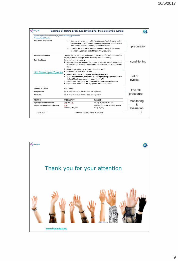
Example of testing procedure (cycling) for the electrolysis system
preparation
Set of
cycles
Overall
procedure
Monitoring
&
evaluation
http://www.hpem2gas.eu
conditioning
www.hpem2gas.eu
Thank you for your attention