
High Performance Horizontal Machining Center
24
High Performance Horizontal Machining Center
Transcript of High Performance Horizontal Machining Center

High Performance Horizontal Machining Center
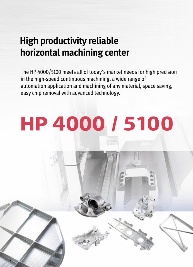
The HP 4000/5100 meets all of today's market needs for high precision
in the high-speed continuous machining, a wide range of
automation application and machining of any material, space saving,
easy chip removal with advanced technology.
High productivity reliable
horizontal machining center
2
3

High Speed Spindle
2222 kkWW1144000000 rr//mmiinn{opt : 20000 r/min}
MMaaxx.. ssppiinnddllee ssppeeeedd MMoottoorr ((3300mmiinn))
● Standard 14000 r/min (18.5/22kW)
■Spindle power-torque diagram
● Option 20000 r/min (15/18.5kW)
The high speed 14000 r/min 40 taper spindle is a true cartridge type unitsupported by four precision class high speed bearings which arepermanently greased and lubricated. The spindle is driven by a hightorque 22 kW A.C. motor delivering an impressive 220.5 N.m.
High speed and precision with advanced technology
SPINDLE SPEED (r/min)
POWER (kW)TORQUE (N.m)
18.5S2(10min.)
S1(Cont.)
S1(C
ont.)
2000010000600040002000
9.69
6.53
1.73
1.43
15
10
2.45
1.63
1500
0.90.81
S2(1
0min
)
S2(10min.)
S1(Cont.)
TORQUE (N.m)
SPINDLE SPEED (r/min)
POWER (kW)
1.201.52
16.3219.4922.55
14000
S1(Cont.)
S2(30min.)18.522.0
26001100950
0
S2(15min.)S1(Cont.)
S3(25%ED)
S3(25%
ED)
S1(Con
t.)
S2(15m
in.)
8.256.94
4

OOiill ccoooolleerr
DDuuaall ccoonnttaacctt ssyysstteemm ((BBiigg pplluuss::SSttdd..)) HHSSKK SSppiinnddllee ((OOpptt..))
TTooooll ccllaammppiinngg ffoorrccee
The refrigerated cooling system maintains auniform spindle temperature required forhigh accuracy and extended production.Thermo sensors regulate the temperature ofthe oil which is circulated through oiljackets around the spindle, as well as thedrive shaft bearings, gears, and motorflanges.
1100000000NN
The HSK shank system with two restrained faces simultaneouslycouples the taper portion of the shank and the flange end face.The hollow 1/10 taper changes flexibly while the flange end facefit tightly to the spindle nose.
Variable Spindle
The dual contact system offers simultaneous dual contactbetween the machine spindle face and toolholder flange face, aswell as the machine spindle taper and long toolholder tapershank. This system is based on the most currently availablestandards for BT, DIN and CAT flange tooling.
■Higher rigidity
■Improved ATC repeatability, surface finish and higher precision machine
■Extended tool life
Dual contact faces
P
T
OJP OJT
M
OIL COOLER
■Improved high speed and heavy duty cutting performance
■Improved machining accuracy
5

4400 ttoooollss {{OOpptt :: 6600//112200//117700}}
TTooooll ssttoorraaggee ccaappaacciittyy
The ATC is composed of tool magazine andchange arm. The tools are selected by a fixedaddress method that follows the shorter path. Alltools are returned to the pots from which theywere originally taken so that collision problemsinvolving large-sized tools need to be consideredonly once when they are first mounted.
11..00 ss ((TT--TT--TT))
TTooooll cchhaannggee ttiimmee
Sophisticated mechanisms drasticallyreduce non-cutting time.
AAuuttoommaattiicc ttooooll cchhaannggeerr
D m
m
L mm
MMaaxxiimmuumm ttooooll ssiizzee
Tool Magazine
ØØ7755 mmmm ((CCoonnttiinnuuoouuss))
ØØ114400 mmmm ((AAddjjaacceenntt ppoorrttss aarree eemmppttyy))
Max. tool diameter
333300 mmmm ((HHPP 44000000))440000 mmmm ((HHPP 55110000))
Max. tool length
1100 kkggMax. tool weight
6

11..44 ss ((00 9900。。))
11。。Minimum table indexing angle
Table indexing time
TTaabbllee
The possibility that chips might degrade the meshing accuracy of the palletpositioning mechanism increases at higher machining speeds. On the HP5100 strong jets of air are discharged from the tapered cones when a pallet ischanged to clean any chips from the cones and assure accurate palletpositioning.
Automatic Pallet Changer
D mm
W kg
H m
m
HHPP 44000000 HHPP 55110000
PPaalllleett ssiizzee 400×400mm 500×500mm
MMaaxx..wwoorrkkppiieeccee ssiizzee Ø600×H 800mm Ø800×H 930mm
MMaaxx..wwoorrkkppiieeccee wweeiigghhtt 400 kg 500 kg
MMaaxx.. WWoorrkkppiieeccee SSiizzee..
HP 4000/5100 are equipped with rotary shuttle type APC(Automatic PalletChanger) as a standard feature. It provides high reliability and wide workingarea for easy setup. The pallet changer is rigidly built and operates with theopening and closing of the splash guard to accomplish pallet changes in 7.0seconds.
Pallet change time
7
77..00 ss ((HHPP 44000000)) // 77..55 ss ((HHPP 55110000))

Rigid Structure Bed and Column
FFEEMM aannaallyyssiissThe machine is designed to build rigidity into a stable body.The construction of the machine was thoroughly examinedfrom the stage of basic design to ensure consistent high-speedand high-accuracy operation. The deformation of the bedwhen subject to a load at the center was simulated to securehigh level rigidity against bending. The HP 4000/5100 has andesign with a basic structure using FEM advanced technology.
TTrraavveell aaxxeess ((XX//YY//ZZ))
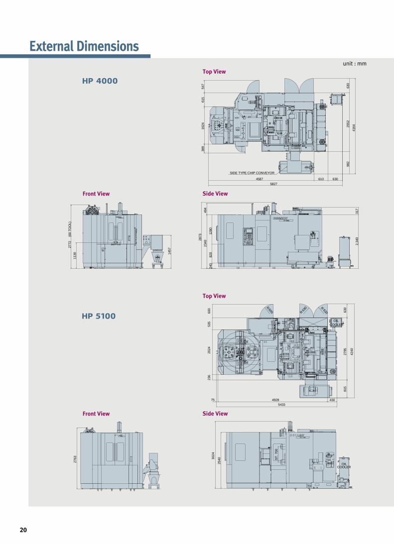
HP 4000
8
660000//556600//660000 mmmm
HP 5000
885500//770000//775500 mmmm

The feed mechanism adopts heavy duty linearmotion roller guideways that provide superioracceleration/deceleration performance to reducenon-cutting time.
BBaallll ssccrreeww nnuutt wwiitthhccoooolliinngg jjaacckkeett ((ssttdd..)) OOiill CCoooolleerr
BBaallll ssccrreeww sshhaaffttccoooolliinngg ((oopptt..))
Machine units are designed minimum thermal transformation by ball screwnut with cooling jacket and ball screw shaft cooling (option) and ‘DBD’ type3-bearings support high accuracy.
Rapid traverse
Minimum thermal transformation for high accuracy
Interface for Fixture
FFiixxttuurree cchheecckk lliisstt (for hydraulic/pneumatic fixtures)
NNuummbbeerr ooff PPoorrttss
2*1×2*2 Line
2*1×3*2 Line
2*1×4*2 Line
2*1×6*2 Line
2*1×8*2 Line
*1 : Pallet No. 1 and No. 2(Number of Pallet)
*2 : Number of port line
HHyyddrraauulliicc ppoowweerr uunniitt
Special requirement
L/min at MPa
Contact Doosan for more information
Guideways and Axis Drives
9
6600 mm//mmiinn

Ergonomic and Eco-Friendly Design EEaassyy sseettuupp
Less waste lubrication oil extends the life time ofthe coolant water and cut down the grime andoffensive smell of the machine inside.
CCoolllleeccttiioonn ooff wwaassttee lluubbrriiccaattiioonn ooiill
Rigorously designed, manufactured and testedmachine covers do not permit coolant leakage inany condition. The factory always keeps ourenvironment clean.
NNoo ccoooollaanntt lleeaakkaaggee
OOiill sskkiimmmmeerr ((oopptt..))
Another suggestion to prolongthe life time of the coolantwater. A belt-driven type oilskimmer picks up and removeswaste oil from the coolant tankthat is easily drained.SSwwiivveelllliinngg
ooppeerraattoorr′′ss ppaanneell
550000 mmmm
11114400 mmmm
Distance to table
Height to table
10
PPoorrttaabbllee MMPPGGkkeeeeppiinngg ssppaaccee

TThhrroouugghh--ssppiinnddllee ccoooollaanntt ssyysstteemm OOiill mmiisstt ccoolllleeccttoorr MMiinniimmuumm QQuuaannttiittyy LLuubblliiccaattiioonn
SShhoowweerr ccoooollaanntt FFlloooodd ccoooollaanntt CCoooollaanntt gguunn
Air+Oil mist
Coolant System
XX--aaxxiiss ((HHPP 44000000 oonnllyy))
Improved Units for Maintenance
DDoouubbllee FFiilltteerriinngg AAiirr SSeerrvvee UUnniitt
Double filtering air service unit is centralizedposition in the machine for easy main-tenance
LLaarrggeesstt LLuubbrriiccaattiioonn PPuummpp && TTaannkk
The large capacity lubrication tank willsupport for silky and stable moving of eachunits.
OOnnee SStteepp SSlliiddee CCoovveerr
The one step slide cover will prevent that units are damaged byminute chip penetration
Misting device
11

Chip Disposal
Hinge type Scraper type Drum filter type
Separate chip conveyor and coolant tank provide easycleaning and maintenance. A telescopic cover, inclined at a250。angle, directs chips into the coil type chip conveyor tokeep the area around the table clean.
From the sliding cover, chips are flushed onto the chipconveyor by the coil screw conveyors to make quick andeasy work of chip removal. The chip conveyor mounting isavailable for rear and side type.
Improved chip disposal
12
Chip conveyor (Option)
×○○
○×○
×△○
×○○
• ○:Available ×:Unavailable △:Asking for information• Some types of chips may not be completely removed from the chip conveyor.• Contact Doosan for more information.
Steel Cast Aluminum andnonferrous metals
Specifications
Compound
Hinge type
Scraper type
Drum filter type

FFaaccee mmiillll Carbon steel (SM45C)
Ø80 Face mill (6Z)
DDrriillll Carbon steel (SM45C)
Ø49 Drill (2Z)
TTaapp Carbon steel (SM45C)
Ø38.5 Drill
68mm
3mm49mm
68mm
3mm
100mm
3mm60mm
68mm
3mm49mm49mm
100mm
3mm60mm
68mm
3mm49mm
100mm
3mm60mm
FFaaccee mmiillll Aluminum
Ø100 Face mill (7Z)
DDrriillll Carbon steel (GC25)
Ø49 Drill (2Z)
TTaapp Carbon steel (GC25)
68mm
3mm49mm
100mm
3mm60mm
100mm
3mm
68mm
3mm49mm
100mm
3mm60mm60mm
68mm
3mm49mm
100mm
3mm60mm
Machining rate
Spindle speed Feedrate
Machining rate
Spindle speed Feedrate
Tool
Spindle speed Feedrate
Cutting Performance
13
8855 cm3/min
116600 rr//mmiinn 4455 mmmm//mmiinn
771144 cm3/min
995500 rr//mmiinn 33550000 mmmm//mmiinn
MM4422××PP44..55112200 rr//mmiinn 554400 mmmm//mmiinn
Machining rate
Spindle speed Feedrate
Machining rate
Spindle speed Feedrate
Tool
Spindle speed Feedrate
330000 cm3/min
118800 rr//mmiinn 116600 mmmm//mmiinn
33112200 cm3/min
1144000000 rr//mmiinn 1133000000 mmmm//mmiinn
MM4422××PP44..55220000 rr//mmiinn 11220000 mmmm//mmiinn

11500
8500
HHPP 55110000
Flexible Multi Pallet SystemTTooooll mmaaggaazziinnee
Numerous Variations to meet production efficiency needs.
HHPP 55110000
unit : mm
Application technology of Multi-pallet system
is the best solution for the high productivity
in the machining shop.
AApppplliiccaattiioonn ooff mmuullttii ppaalllleett ssyysstteemm
Name HP 5100 (2 sets)
Number of Setup Station 1Storage Capacity (500×500) 18 cells
■ 7-Station Round Type Multi Pallet Magazine
■High Productivity & availability■Flexible production solutions■High efficiency system■Compact designed technology■Easy to extend stations
(HP 4000/5100 : 7, 9, 11, 13st)
14
60-tool (opt.)
120-tool (opt.)
170-tool (opt.)

Sample Workpiece
X-frame Inboard door Ring-rib Water pump cover
Control valve Front cover Brake caliper Casting
Control valve Pump body Cylinder/Crank case Grip arm
15

Standard Features
Flood coolant Operator call lamp (red/yellow/green)
FANUC 18i-MB controller Portable MPG
Work light APC operator's panel
Rigid tapping Oil cooler
Screw conveyor
16

Multi pallet system 120 Tools Matrix magazine (170 Tools)
Linear scale feedback system Automatic measuring systemAutomatic tool length measurement with senser
Built in Rotary Table (0.001。) FMS Through the spindle coolant
Chip conveyor / Bucket T-slot pallet Shower coolant
• Air gun
• Automatic power off
• Center bush
• Coolant chiller
• Coolant gun
•Hyd. cooling / Heating device
•Hydraulic line for fixture
•HSK tooling
• Rear type chip conveyor
• Test bar
Optional Equipment
17

■High compact CNC is realized through LCD display with integrated CNC and a flash memory card interface is standard features.■Provides many support functions for set-ups, such as tool measurement, workpiece measurement at the original point, and workpiece
measurement inside the machine.■Uses one display screen to perform all operations including programming,
checking by animation, and real machining.■User-Friendly Operation : Soft key Selection of Comprehensive Cycle Library
SSttaannddaarrdd FFeeaattuurreess
Easy Operating System
Guide for machining preparationIn preparation for machining, simple instructionson a selected screen allow to measure the settingerror of workpiece and tool offset value forautomated adjustment.
18

Tool Monitoring System (Opt.)
■For machining center, turning center and compound machine with millingand turning.
■Solid modeling provides high speed animation. (TFT-LCD Color Only)
■Icon menu soft-keys provide convenient programming for sophisticated milling and turning.
■Measurement cycles provide automatic offset measurement of workpiece (Available for machining center and for compound machine).
■Registration of parameter sets for high speed machining and/or for highprecision machining with machine configurations.
■Instruction of precision level for desired machining selects appropriate
parameters automatically.
■Precision level can be instructed through NC program.
Easy operation system
One single screen provides handy operation guidancefor programming through machine operation.
One single screen provides convenient operation ¶meter setting for high speed and high precisionmachining instructions.
Machining condition selecting function
TTooooll llooaadd mmoonniittoorriinngg ssyysstteemm TTooooll mmaannaaggeemmeenntt ffuunnccttiioonnTool Monitoring System is one of safety
functions to protect Tool and Spindle against
a possible damage of abnoraml load caused
by tool wear and breakage or others. This
system montitors the tool status during
machine operation by detecting the abnormal
load of exch axis and spindle.
•The screen shows a tool and pallet No.,
load meter of each axis and spindle limit
load.
•This functions consisted of tool pre-check
function, substitutive tool selection with
tool life management and different tool &
port number command function.
19
SIDE TYPE CHIP CONVEYOR
4587
5827
1624
615
547
389
630
2552
982
4164
610 630
1457
1130
2772
(60
TO
OL)
1280
240
820
317
2,34
0
2340
494
2873
OIL COOLER
630R
630
R
600R
815
2795
630
4240
75 4928 4305433
236
2024
535
600
2763
OILCOOLER
254030
24 700
ST
.
unit : mm
External Dimensions
20
Front View Side View
Top View
Front View Side View
Top View

unit : mm
unit : mm
Pallet Dimensions
Tool Shank
MAS403 BT40 DIN40
CAT40Nikken PS806
22.8 25
16.1
ø63.
55ø5
6.25
7.07
11.1
ø44.
45
"T"7/24 TAPER
TAPER GAGE LINE
60˚
ø17
ø23
"T" 15˚
ø14
28 26
ø17 20
42
ø1930˚
68.43515.92 3.18
ø7 H
OLE
ø44.
7
15˚
TAPER GAGE LINE
ø17
ø14
ø19
ø44.
45
ø63.
55ø5
0
ø17
11.1
15.9 3.2 68.4
35
M16xP2.022.825
204
2
ø23 30˚
ø7 H
OLE
7/24 TAPER
M16xP2.0
ø7
ø72.
3
ø75.
68
44.4
5
16.6
25 65.4
ø23
ø19
ø17
ø14
15˚
30˚
M16xP2.0
23
25 29 4
2
2
60˚ø10
TAPER GAGE LINE
7/24 TAPER
M16x2.0 TAP
ø17H
7
ø19
ø63
ø53
16.118
.5
18.5
2628
60˚
HOLE FOR M1655 55
40
400
40 4080
8080
8040
400
25
1836
80 80 80 80
24-M16X2 TAP,DP30
HOLE FOR M16
5010010010010050
24-M16X2 TAP,DP30
36
18
25
7575
500
500
5010
010
010
010
050
21

■Assembly & Operation tools
■Coolant tank flood coolant & cleaning Flushing
■Door interlock for safety
■FANUC 18i-MB controller
■Full enclosure spash guard
■Installation parts
■Operator call lamp (red, yellow, green)
■Rigid tapping
■Screw conveyor
■Spindle Cooling unit & oil cooler
■Work light
·Design and specifications are subject to change without notice.·Doosan is not responsible for difference between the information in the catalogue and the actual machine.
Machine Specifications
Note : { } are optional
Descriptions HP 4000 HP 5100X-axis mm 600 850
Y-axis mm 560 700
Z-axis mm 600 750
Distance from spdl center to pallet top mm 50~610 50~750
Distance from spdl nose to table center mm 150~750 150~900
Pallet size mm 400×400 500×500
Pallet loading capacity kg 400 500
Pallet surface 24-M16×P2.0
Pallet index degree deg 1{0.001}
Max. spindle speed r/min 14000{20000}
Spindle taper ISO#40, 7/24Taper
Max. spindle torque (25% ED) N.m 220.5
Rapid traverse rate(X/Y/Z) m/min 60
Cutting feedrate mm/min 30000
Type of tool shank MAS403 BT40
Tool storage capacity 40{60/120/170}
Max. tool diameter mm ø75
Max. tool diameter without adjacent tools mm ø140
Max. tool length mm 330 400
Max. tool weight kg 10
Method of tool selection Fixed address
Tool change time(tool-to-tool) s 1.0
Tool change time(chip-to-chip) s 3.5
Number of pallet ea 2 2{7/9/11/13}
Type Rotary shuttle
Pallet change time s 7.0 7.5
Pallet rotation in loading station deg 90
Spindle motor (30 min) kW 18.5/22
Feed motor(X/Y/Z/B) kW 7.0/7.0/7.0/2.7
Electric power supply (Rated capacity) kVA 65
Compressed air supply Mpa 0.54
Coolant tank capacity L 640
Lubrication tank capacity L 4.3
Machine height mm 2880 3030
Machine dimension mm 5400×2560 5600×2800
Machine weight kg 14000 15000
Travel
Table
Spindle
Feedrate
Automatic
tool changer
Automatic
pallet changer
Motor
Machine size
Tank capacity
Power source
Standard Feature
22

- Program number O4-digits- Program protect- Program stop / end M00 / M02,M30- Programmable data input Tool offset and work offset are entered by G10, G11- Sub program Up to 4 nesting- Tape code ISO / EIA Automatic discrimination- Work coordinate system G54 - G59- Additional work coordinate system(48 Pair) G54.1 P1 - 48 pairs- Coordinate system rotation G68, G69- Extended part program editing- Optional angle chamfering / corner R- Macro executor
OOTTHHEERRSS FFUUNNCCTTIIOONNSS ((OOppeerraattiioonn,, SSeettttiinngg && DDiissppllaayy,, eettcc))- Alarm display- Alarm history display- Clock function- Cycle start / Feed hold- Display of PMC alarm message Message display when PMC alarm occurred- Dry run- Ethernet function(Embeded)- Graphic display Tool path drawing- Help function- Loadmeter display- MDI / DISPLAY unit 10.4 color LCD, Keyboard for data input, soft-keys- Memory card interface- Operation functions Tape / Memory / MDI / Manual- Operation history display- Program restart- Run hour and part number display- Search function Sequence NO. / Program NO.- Self - diagnostic function- Servo setting screen- Single block- External data input- Multi language display
OOPPTTIIOONNAALL SSPPEECCIIFFIICCAATTIIOONNSS- 3-dimensional coordinate conversion- 3-dimensional tool compensation- 3rd / 4th reference return standard only for HM 1000- Addition of tool pairs for tool life management 512 pairs- Additional controlled axes max. 6 axes in total- Additional work coordinate system G54.1 P1 - 300 (300 pairs )- AI HPCC* (High Precision Contour Control) with 64 bit Risc 600 block preview- Automatic corner override G62- Chopping function G81.1- Cylindrical interpolation G07.1- Data server- Dynamic graphic display Machining profile drawing- Exponential interpolation- Interpolation type pitch error compensation- EZ Guide i (Doosan infracore Conversational Programming Solution) with 10.4 Color TFT- Tape format for FS15 - Increment system 1/10- Figure copying G72.1, G72.2- Manual handle feed 2/3 unit- Handle interruption- High speed skip function- Involute interpolation G02.2, G03.2- Look ahead control G08- Machining time stamp function- No. of Registered programs 400 / 1000 ea- Number of tool offsets 400 / 499 / 999 ea- Optional block skip addition 9 blocks- Part program storage 1280 / 2560 m- Playback function- Polar coordinate command G15 / G16- Polar coordinate interpolation G12.1 / G13.1- Programmable mirror image G50.1 / G51.1- Remote buffer- Scaling G50, G51- Single direction positioning G60- Stored stroke check 2 / 3- Tool load monitoring function(doosan)- Doosan tool management package Ⅰ- Tool position offset G45 - G48- Position switch
AAXXEESS CCOONNTTRROOLL- Controlled axes 4 (X,Y,Z,B)- Simultaneously controllable axes
Positioning(G00)/Linear interpolation(G01) : 3 axesCircular interpolation(G02, G03) : 2 axes
- Backlash compensation- Emergency stop / overtravel- Follow up- Least command increment : 0.001mm / 0.0001″- Least input increment : 0.001mm / 0.0001″- Machine lock all axes / Z axis- Mirror image Reverse axis movement
(setting screen and M - function)- Stored pitch error compensation Pitch error offset compensation for each axis- Stored stroke check 1 Overtravel controlled by software
IINNTTEERRPPOOLLAATTIIOONN && FFEEEEDD FFUUNNCCTTIIOONN- 2nd reference point return G30- Circular interpolation G02, G03- Dwell G04- Exact stop check G09, G61(mode)- Feed per minute mm / min- Feedrate override (10% increments) 0 - 200 %- Jog override (10% increments) 0 - 200 %- Linear interpolation G01- Manual handle feed(1 unit)- Manual handle feedrate 0.1/0.01/0.001mm- Override cancel M48 / M49- Positioning G00- Rapid traverse override F0 (fine feed), 25 / 50 / 100 %- Reference point return G27, G28, G29- Skip function G31- Helical interpolation- NANO AICC (AI Contour Control) 80 block preview- Thread cutting, synchronous cutting- Program restart- Automatic corner deceleration- Feedrate clamp by circular radius- Linear ACC/DEC before interpolation- Linear ACC/DEC after interpolation- Control axis detach- Rapid traverse bell-shaped acceleration/deceleration- Dual position feedback
SSPPIINNDDLLEE && MM--CCOODDEE FFUUNNCCTTIIOONN- M- code function M 3 digits- Spindle orientation- Spindle serial output- Spindle speed command S5 digits- Spindle speed override (10% increments) 10 - 150 %- Spindle output switching - Retraction for rigid tapping- Rigid tapping G84, G74
TTOOOOLL FFUUNNCCTTIIOONN- Cutter compensation C G40, G41, G42- Number of tool offsets 200 ea- Tool length compensation G43, G44, G49- Tool number command T3 digits- Tool life management Geometry / Wear and Length / Radius offset memory- Tool offset memory C
PPRROOGGRRAAMMMMIINNGG && EEDDIITTIINNGG FFUUNNCCTTIIOONN- Absolute / Incremental programming G90 / G91- Auto. Coordinate system setting- Background editing- Canned cycle G73, G74, G76, G80 - G89, G99- Circular interpolation by radius programming- Custom macro B- Custom size 512kb- Addition of custom macro common variables- Decimal point input- I / O interface RS - 232C- Inch / metric conversion G20 / G21- Label skip- Local / Machine coordinate system G52 / G53- Maximum commandable value ±99999.999mm (±9999.9999 inch)- No. of Registered programs 200 ea- Optional block skip- Optional stop M01- Part program storage 640 m
NC Unit Specifications (Fanuc 18i-MB)
23

Design and specifications are subject to change without prior notice. EU0805SPi-ser
Sales & Support Network
ARGENTINA/Rosario AUSTRALIA/Melbourne/Sydney AUSTRIA/Vienna BELGIUM/Gullegem BRAZIL/Sao paulo BULGARIA/Sofia CANADA/Edmonton/Montreal/Toronto
/Vancouver CHILE/Santiago CHINA/Beijing/Chongqing/Guangzhou/Shanghai/Shenyang COLOMBIA/Bogota CZECH/Brno DENMARK/Randers EGYPT/Cairo FINLAND/Tampere
FRANCE/Annecy GERMANY/Dusseldorf GREECE/Athens HONG KONG/Kowloon HUNGARY/Budapest INDIA/Bangalore/Pune INDONESIA/Jakarta ISRAEL/Herzlia
ITALY/Parma MALAYSIA/Puchong MEXICO/Guadalajara /Mexico City /Monterrey /Vera Cruz NETHERLANDS/Goorn NEW ZEALAND/Auckland NORWAY/Oslo PAKISTAN
/Islamabad POLAND/Krakow PORTUGAL/Lisbon ROMANIA/Bucharest RUSSIA/Moscow SINGAPORE/Singapore SLOVENIA/Ljubljana SOUTH AFRICA/Kempton Park
SPAIN/Barcelona SWEDEN/Stockholm SWITZERLAND/Zurich TURKEY/Istanbul THAILAND/Bangkok U.A.E/Sharjah U. K./Leamington U.S.A./Atlanta/Birmingham
/Charlotte/Chicago/Cincinnati/Cleveland/Dallas/Denver/Detroit/Houston/Indianapolis/Kansas City/Little Rock/Los Angeles/Milwaukee/Minneapolis/New Jersey / New Orleans/Norfolk
/Philadelphia/Phoenix/Pittsburgh/Portland/Rochester/Salt Lake City/San Diego/San Francisco/Seattle/Springfield/St. Louis/Tampa/Tulsa VENEZUELA/Valencia VIETNAM/Hanoi
Head Office : Doosan Tower 22nd FL., 18-12, Euljiro-6Ga, Jung-Gu, Seoul, Korea 100-730Tel : ++82-2-3398-8651 Fax : ++82-2-3398-8699 E-mail : [email protected]
Doosan Infracore America Corp.: 8 York Avenue, West Caldwell, NJ 07006, U.S.A.Tel : ++1-973-618-2500 Fax : ++1-973-618-2501
Doosan Infracore Germany GmbH : Hans-Böckler-Strasse 29, D-40764 Langenfeld-Fuhrkamp, Germany.Tel : ++49-2173-8509-10 Fax : ++49-2173-8509-60
China Representative Office : 9-101 Xinmao Building, 99 Tianzhou Road, Caohejing Hi-Tech Development Shanghai, China 200233 Tel : ++86-21-5445-1155 (812,815) Fax : ++86-21-64403389
http://domss.doosaninfracore.com


![400 mm PALLET HORIZONTAL MACHINING …training.methodsmachine.com/_assets/machines/41d6e585-e2f5-4560-91...horizontal machining centers ... Spindle nose to pallet center mm [inch]](https://static.fdocuments.us/doc/165x107/5ab571647f8b9a6e1c8cd8d8/400-mm-pallet-horizontal-machining-machining-centers-spindle-nose-to-pallet.jpg)


