High performance computing · High performance computing (HPC) refers to the computing system,...
48
HIGH PERFORMANCE COMPUTING APPLIED TO CLOUD COMPUTING Li Luxingzi Thesis Technology, Communication and Transport Programme in Information Technology 2015
Transcript of High performance computing · High performance computing (HPC) refers to the computing system,...
HIGH PERFORMANCE COMPUTING APPLIED TO CLOUD COMPUTING
Li Luxingzi
Thesis Technology, Communication and Transport
Programme in Information Technology
2015
Technology, Communication and Transport Degree programme in Information Technology
Abstract of thesis
Author Li Luxingzi Year 2015 Supervisor Veikko Keränen Title of thesis High Performance Computing Applied to Cloud Computing No. of pages 48
The purpose of this thesis was to introduce high performance computing and cloud computing. The purpose was also to describe how to apply high performance computing to cloud computing as well as its possibilities and challenges. There were two case studies in the thesis project to present the application of cloud computing. Both quantitative and qualitative methods were used in this research. The majority of materials were from books and Internet resources. The thesis may be useful to students, teachers, and people who are interested in information technology, mathematics and science.
Key words high performance computing, cloud computing, cluster
CONTENTS
1 INTRODUCTION ............................................................................................. 6
2 HIGH PERFORMANCE COMPUTING ............................................................ 7
2.1 Background of High Performance Computing ........................................ 7
2.1.1 Overview of High Performance Computing .................................. 7
2.1.2 History of High Performance Computing ..................................... 8
2.2 High Performance Computing Architecture ............................................ 9
2.2.1 Five Major Parts of High Performance Computing System .......... 9
2.2.2 Building High Performance Computing Cluster ......................... 10
2.3 Performance and Optimization ............................................................ 14
2.3.1 Peak Performance ..................................................................... 14
2.3.2 Performance Improvements ...................................................... 14
2.4 Quantitative Analysis of Performance of Linux High Performance
Computing Cluster ..................................................................................... 16
2.4.1 Metrics ....................................................................................... 16
2.4.2 Arithmetical Operation Analysis of Linux Cluster System .......... 17
2.5 Top 500 List ......................................................................................... 19
2.6 Parallel Computing .............................................................................. 22
3 CLOUD COMPUTING ................................................................................... 25
3.1 Overview of Cloud Computing ............................................................. 25
3.1.1 Definition of Cloud Computing ................................................... 25
3.1.2 Service Models .......................................................................... 26
3.2 Service-Oriented Infrastructure of Cloud Computing ........................... 28
3.2.1 Service-Oriented Infrastructure Framework ............................... 28
3.2.2 Cloud Modules of Service-Oriented Infrastructure Structure ..... 29
3.3 Typical Technologies ........................................................................... 33
3.3.1 Data Storage Technology .......................................................... 33
3.3.2 Distributed Programming Technology ........................................ 36
3.3.3 Automatic Deployment Technology ........................................... 37
3.4 Case Study .......................................................................................... 38
3.4.1 Cloud Computing to E-Commerce ............................................. 38
3.4.2 Information Ecosystem of Cloud Computing .............................. 39
4 HIGH PERFORMANCE COMPUTING APPLIED TO CLOUD COMPUTING 42
4.1 Comparison Application Profile of Cloud Computing and High
Performance Computing ............................................................................ 42
4.2 High Performance Computing Deployments in Cloud Computing
Environments ............................................................................................. 43
5 CONCLUSION ............................................................................................... 46
REFERENCES ................................................................................................. 47
LIST OF FIGURES
Figure 1. Five Major Parts in Distributed-Memory High Performance Computing
System (Gerber 2012) ...................................................................................... 10
Figure 2. Building High Performance Computing Cluster .................................. 10
Figure 3. Processor Pipelining (Jacob 2015) .................................................... 15
Figure 4. Prototypical Linux Cluster .................................................................. 17
Figure 5. Top 10 Ranking (Wikimedia Foundation, Inc. 2015) .......................... 20
Figure 6. Performance Development (TOP500.org. 2014) ............................... 21
Figure 7. Country System and Vendor System Share (TOP500.org. 2014) ...... 21
Figure 8. Vertical Structure of a Superstep of Bulk Synchronous Parallel
(Wikimedia Foundation, Inc. 2014) ................................................................... 23
Figure 9. Process of Parallel Solution ............................................................... 24
Figure 10. Deployment and Service Models of Cloud Computing ..................... 28
Figure 11. Service-Oriented Infrastructure Framework (Smoot-Tan 2012) ...... 29
Figure 12. The Control Flow and the Data Flow................................................ 36
Figure 13. Automatic Deployment Framework .................................................. 37
Figure 14. Information Ecosystem of Cloud Computing .................................... 40
Figure 15. Internet Solution of the Integration of High Performance Computing
and Cloud Computing (H3C Technologies Co. 2015) ....................................... 44
Figure 16. Deployment of the IRF II (The Second Generation of Intelligent
Resilient Framework) (H3C Technologies Co. 2015) ........................................ 45
Table 1. Example of Hardware and Software Configuration (Based on 168-Node
IBM Server) ...................................................................................................... 13
Table 2. Example of Security Policy of Infrastructure Cloud ............................ 33
Table 3. Differences of Google File System and the General Distributed File
System .............................................................................................................. 35
6
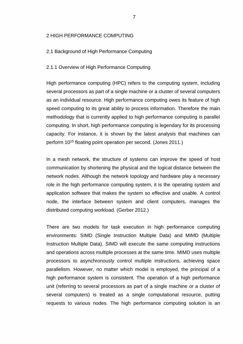
1 INTRODUCTION
Nowadays, high performance computing is more and more important for the
economic and technological development. The high performance computing
also becomes an indicator to measure the power of a country. Therefore, it is
important and meaningful to improve the performance and universality of high
performance computing.
In addition, cloud computing can provide users with easier computing service
through various hardware devices. Applying high performance computing to
cloud computing become a meaningful challenge for many scientists and
professional talents. The current research results are listed in the thesis.
The purpose of the thesis is to introduce high performance computing and cloud
computing. The architecture and performance of high performance computing
are described in the Chapter 2. The definition of cloud computing and its typical
technologies are presented in the Chapter 3. There are two case studies in the
thesis project, as the examples of application of cloud computing. Quantitative
as well as qualitative analysis methods are used to the research.
7
2 HIGH PERFORMANCE COMPUTING
2.1 Background of High Performance Computing
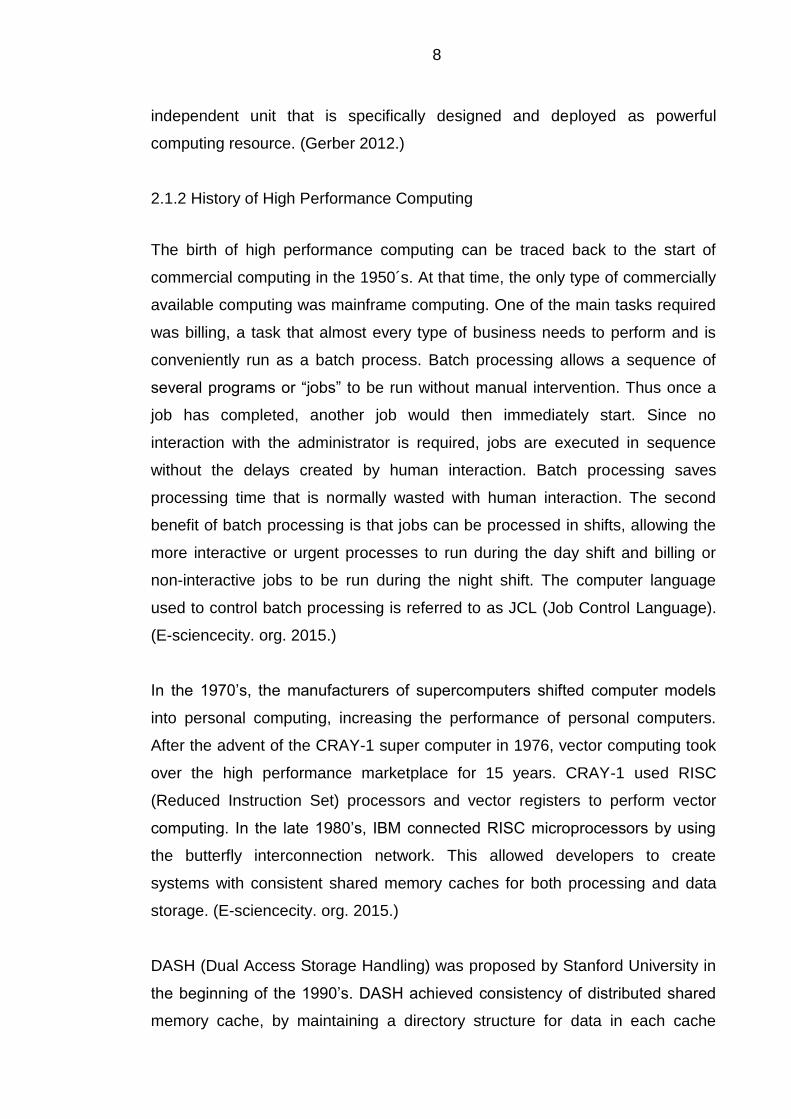
2.1.1 Overview of High Performance Computing
High performance computing (HPC) refers to the computing system, including
several processors as part of a single machine or a cluster of several computers
as an individual resource. High performance computing owes its feature of high
speed computing to its great ability to process information. Therefore the main
methodology that is currently applied to high performance computing is parallel
computing. In short, high performance computing is legendary for its processing
capacity. For instance, it is shown by the latest analysis that machines can
perform 1015 floating point operation per second. (Jones 2011.)
In a mesh network, the structure of systems can improve the speed of host
communication by shortening the physical and the logical distance between the
network nodes. Although the network topology and hardware play a necessary
role in the high performance computing system, it is the operating system and
application software that makes the system so effective and usable. A control
node, the interface between system and client computers, manages the
distributed computing workload. (Gerber 2012.)
There are two models for task execution in high performance computing
environments: SIMD (Single Instruction Multiple Data) and MIMD (Multiple
Instruction Multiple Data). SIMD will execute the same computing instructions
and operations across multiple processes at the same time. MIMD uses multiple
processors to asynchronously control multiple instructions, achieving space
parallelism. However, no matter which model is employed, the principal of a
high performance system is consistent. The operation of a high performance
unit (referring to several processors as part of a single machine or a cluster of
several computers) is treated as a single computational resource, putting
requests to various nodes. The high performance computing solution is an
8
independent unit that is specifically designed and deployed as powerful
computing resource. (Gerber 2012.)
2.1.2 History of High Performance Computing
The birth of high performance computing can be traced back to the start of
commercial computing in the 1950´s. At that time, the only type of commercially
available computing was mainframe computing. One of the main tasks required
was billing, a task that almost every type of business needs to perform and is
conveniently run as a batch process. Batch processing allows a sequence of
several programs or “jobs” to be run without manual intervention. Thus once a
job has completed, another job would then immediately start. Since no
interaction with the administrator is required, jobs are executed in sequence
without the delays created by human interaction. Batch processing saves
processing time that is normally wasted with human interaction. The second
benefit of batch processing is that jobs can be processed in shifts, allowing the
more interactive or urgent processes to run during the day shift and billing or
non-interactive jobs to be run during the night shift. The computer language
used to control batch processing is referred to as JCL (Job Control Language).
(E-sciencecity. org. 2015.)
In the 1970’s, the manufacturers of supercomputers shifted computer models
into personal computing, increasing the performance of personal computers.
After the advent of the CRAY-1 super computer in 1976, vector computing took
over the high performance marketplace for 15 years. CRAY-1 used RISC
(Reduced Instruction Set) processors and vector registers to perform vector
computing. In the late 1980’s, IBM connected RISC microprocessors by using
the butterfly interconnection network. This allowed developers to create
systems with consistent shared memory caches for both processing and data
storage. (E-sciencecity. org. 2015.)
DASH (Dual Access Storage Handling) was proposed by Stanford University in
the beginning of the 1990’s. DASH achieved consistency of distributed shared
memory cache, by maintaining a directory structure for data in each cache
9
location. Since then, several major architectures have begun to be mixed
together. Today, more and more parallel computer systems use commercial
microprocessors and the interconnection network structure. This distributed
memory parallel computer system is known as clustering. Parallel computers
have entered a new era where there is currently unprecedented development.
(E-sciencecity. org. 2015.)
2.2 High Performance Computing Architecture
2.2.1 Five Major Parts of High Performance Computing System
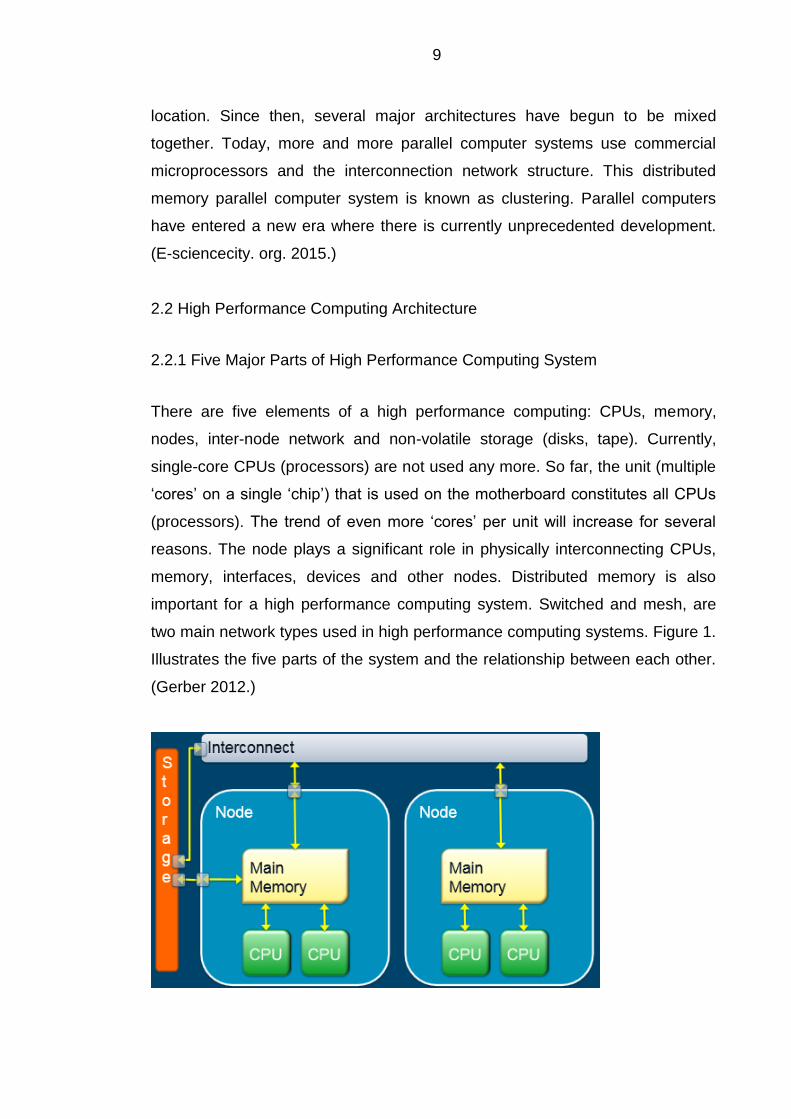
There are five elements of a high performance computing: CPUs, memory,
nodes, inter-node network and non-volatile storage (disks, tape). Currently,
single-core CPUs (processors) are not used any more. So far, the unit (multiple
‘cores’ on a single ‘chip’) that is used on the motherboard constitutes all CPUs
(processors). The trend of even more ‘cores’ per unit will increase for several
reasons. The node plays a significant role in physically interconnecting CPUs,
memory, interfaces, devices and other nodes. Distributed memory is also
important for a high performance computing system. Switched and mesh, are
two main network types used in high performance computing systems. Figure 1.
Illustrates the five parts of the system and the relationship between each other.
(Gerber 2012.)
10
Figure 1. Five Major Parts in Distributed-Memory High Performance Computing
System (Gerber 2012)
2.2.2 Building High Performance Computing Cluster
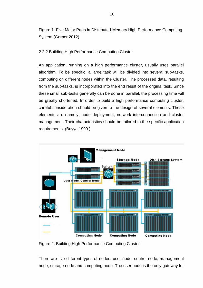
An application, running on a high performance cluster, usually uses parallel
algorithm. To be specific, a large task will be divided into several sub-tasks,
computing on different nodes within the Cluster. The processed data, resulting
from the sub-tasks, is incorporated into the end result of the original task. Since
these small sub-tasks generally can be done in parallel, the processing time will
be greatly shortened. In order to build a high performance computing cluster,
careful consideration should be given to the design of several elements. These
elements are namely, node deployment, network interconnection and cluster
management. Their characteristics should be tailored to the specific application
requirements. (Buyya 1999.)
Figure 2. Building High Performance Computing Cluster
There are five different types of nodes: user node, control node, management
node, storage node and computing node. The user node is the only gateway for
11
outsiders to access to cluster system. Users usually need to log in from the
node to compile and run the tasks. Fault-tolerant design is achieved with
hardware redundancy which should be designed into the system to ensure high
availability of the user node. Control node mainly takes responsibility of
supplying computing node with basic network services, such as DHCP
(Dynamic Host Control Protocol), DNS (Domain Name Service), NFS (Network
File Service), and dispatching tasks to the computing node. For example, the
cluster job scheduler is normally run on this node. Moreover, the control node
decides availability of the network. If the control node suffers a catastrophic
failure, all the computing nodes will also be out of operation. (Kalcher 2007.)
The management node controls various management tasks in the cluster
system. Thus, the management software of the cluster is also running on this
node. The storage node refers to the data storage and data server for the
cluster system. A single storage node is not enough when the data levels are in
the TB (Terabyte) range. Thus, storage networks are also required. Storage
nodes typically require the following configuration: RAID (Redundant Array of
Independent Disks) server to guarantee data security, and high-speed network
to ensure adequate speed for data transmission. Computing nodes are the core
of the cluster computing system, and their functions are to compute. The kind of
configuration depends on the application requirements and also the fiscal
budget. A Blade server (a thin electronic circuit board module) is the ideal
choice of computing nodes because of its low physical height, which permits a
high stacking density in an air conditioned machine room cabinet. Also blade
servers have low power consumption, simple installation, as well as many other
favorable characteristics. (Kalcher 2007.)
Since the network directly affects the capacity and performance of the entire
high performance system, the network is the most significant part of the cluster.
According to the survey, the key characteristics of a high speed network are:
low latency and high bandwidth between all nodes. InfiniBand draws HPC
industry’s attention with high-bandwidth and low latencies. InfiniBand is a
technology developed by InfiniBand Association. The InfiniBand solution
includes multiple independent processors which are interconnected with the
12
system network of I/O devices. InfiniBand system can build small processors
with only a few I/O devices, as well as large-scale parallel supercomputers. It is
a scalable solution. (Kalcher 2007.)
Products of the Norwegian company Scali, are cluster management
applications based upon the Linux operation system, which utilize a graphical
management interface. The library of high performance communication and the
integrated software tools from third-parties, allows the system to easily allocate
tasks and monitor the workload on each node in the cluster. Developing their
own application software through a range of software interfaces will reduce
development time and cost of the entire system, and ensure the system
configuration and upgrade flexibility. The most significant feature of their
products is the support of a variety of high speed interconnection networks,
from Gigabit Ethernet, SCI (Serial Communication Interface), Myrinet, to
InfiniBand. (Kalcher 2007.)
13
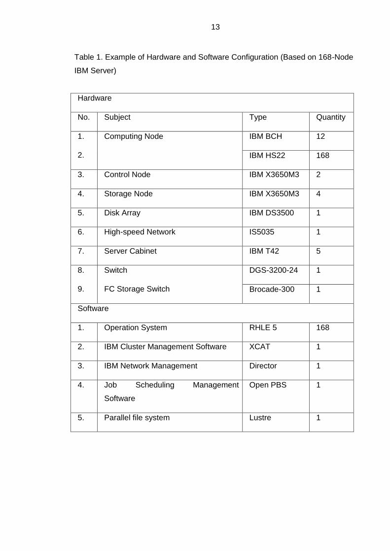
Table 1. Example of Hardware and Software Configuration (Based on 168-Node
IBM Server)
Hardware
No. Subject Type Quantity
1.
2.
Computing Node IBM BCH 12
IBM HS22 168
3. Control Node IBM X3650M3 2
4. Storage Node IBM X3650M3 4
5. Disk Array IBM DS3500 1
6. High-speed Network IS5035 1
7. Server Cabinet IBM T42 5
8.
9.
Switch
FC Storage Switch
DGS-3200-24 1
Brocade-300 1
Software
1. Operation System RHLE 5 168
2. IBM Cluster Management Software XCAT 1
3. IBM Network Management Director 1
4. Job Scheduling Management
Software
Open PBS 1
5. Parallel file system Lustre 1
14
2.3 Performance and Optimization
2.3.1 Peak Performance
All kinds of high performance computing facilities ought to be based on the
different needs of enterprises. Also every high performance computing
application must be specially optimized, which is completely different to
traditional data center requirements. This method of optimization achieves high
performance computing combined with application peak performance. (Jones
2011.)
“The theoretical maximum performance (usually measured in terms of 64-bit (double precision, on most architectures) floating point operations per second) is achievable by a computing system.” (Jones 2011.)
The peak performance of a system is measured by multiplying the clock rate by
floating point operations completed per clock cycle. For example, 2.5 GHz
multiplied by 4 FLOPS (floating-point operations per second) per clock equals to
10 Giga FLOPS per clock cycle, which is rarely achieved. The theoretical peak
performance can limit the unrealistic value. And it additionally offers the
reference way to compare the various platforms. (Jones 2011.)
2.3.2 Performance Improvements
Firstly, an appropriate memory ought to be chosen. There are types of DIMM
(Dual In-line Memory Module) available: UDIMM (Unbuffered Dual In-line
Memory Module), RDIMM (Registered Dual In-line Memory Module), and
LRDIMM (Load-Reduced Dual In-line Memory Module). UDIMM memory is for
handling large-scale workloads with high speed, low cost, non-stable features.
RDIMM memory is stable with reasonable extensibility, but expensive. And it is
conjointly used with several traditional servers. LRDIMM memory is a good
replacement for DIMM with high speed of memory, reducing the load of sever
memory bus and lower dissipation. (Kohlmeyer 2010.)
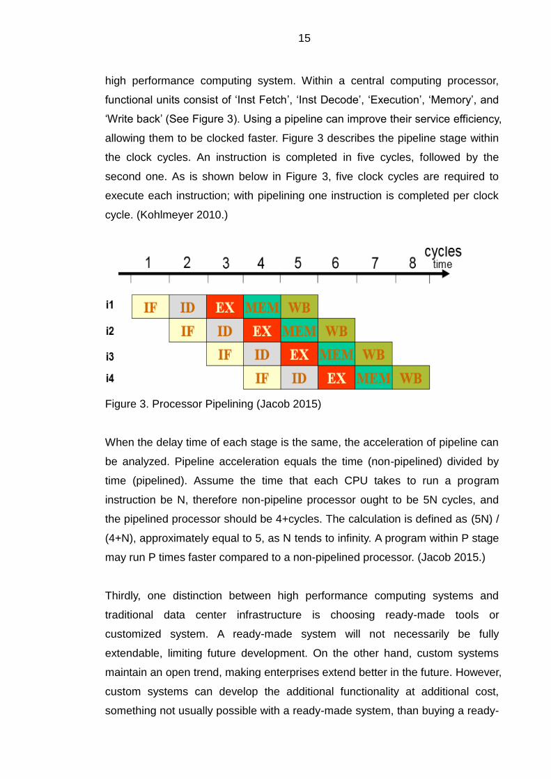
Secondly, pipelining should be introduced for upgrading the performance of a
15
high performance computing system. Within a central computing processor,
functional units consist of ‘Inst Fetch’, ‘Inst Decode’, ‘Execution’, ‘Memory’, and
‘Write back’ (See Figure 3). Using a pipeline can improve their service efficiency,
allowing them to be clocked faster. Figure 3 describes the pipeline stage within
the clock cycles. An instruction is completed in five cycles, followed by the
second one. As is shown below in Figure 3, five clock cycles are required to
execute each instruction; with pipelining one instruction is completed per clock
cycle. (Kohlmeyer 2010.)
Figure 3. Processor Pipelining (Jacob 2015)
When the delay time of each stage is the same, the acceleration of pipeline can
be analyzed. Pipeline acceleration equals the time (non-pipelined) divided by
time (pipelined). Assume the time that each CPU takes to run a program
instruction be N, therefore non-pipeline processor ought to be 5N cycles, and
the pipelined processor should be 4+cycles. The calculation is defined as (5N) /
(4+N), approximately equal to 5, as N tends to infinity. A program within P stage
may run P times faster compared to a non-pipelined processor. (Jacob 2015.)
Thirdly, one distinction between high performance computing systems and
traditional data center infrastructure is choosing ready-made tools or
customized system. A ready-made system will not necessarily be fully
extendable, limiting future development. On the other hand, custom systems
maintain an open trend, making enterprises extend better in the future. However,
custom systems can develop the additional functionality at additional cost,
something not usually possible with a ready-made system, than buying a ready-
16
made system. (Jacob 2015.)
Fourthly, there are some other ways to improve the performance. Dividing
information flow into the parallel flow also contributes to increase running speed.
Once multiple-core implemented, the pipelined and super-scalar CPUs of a
processor, remove the maximum CPU clock rate limitations. Moreover, the
enterprise ought to take responsibility for maintaining the system consistency.
When inconsistency appearing within the cluster, the administrator may
recognize some abnormal changes, affecting application performance.
Considering the potential performance, the IT department requires considered
strategies to confirm the kind of application that runs in the high performance
computing system. Furthermore, efficient data architecture and cooling system
become important attributes because of the high density.
2.4 Quantitative Analysis of Performance of Linux High Performance Computing
Cluster
2.4.1 Metrics
Performance, performance/Watt, performance/ Square foot, performance/dollar
are obviously important to high performance computing cluster. Running such a
system is usually restricted by energy consumption (watts) and volume (square
feet) of the server. Therefore, these two elements, energy consumption and
volume, are calculated in the total cost of ownership (TCO). It will create more
economic profits under control of the total cost of ownership. In addition,
performance density (performance showing in a cluster with certain volume)
and TCO will be attached great importance in practice. (Barragy 2007.)
Here the performance is defined as a sort of calculating rates, such as the
workload completed per day, FLOPS (Floating-point Operations per Second).
The time to complete a given workload is directly related to the speed. Thus,
performance is measured by running workload, which is regenerated to the
required speed in calculating. (Barragy 2007.)
17
2.4.2 Arithmetical Operation Analysis of Linux Cluster System
In the view of a qualitative level, advanced processors, high capacity memory,
excellent network and input/output disk subsystem can realize the best
performance optimization. However, once involved purchasing Linux cluster
facilities under the certain TCO (total cost of ownership), quantitative analysis
should be conducted. The model of Linux high performance computing cluster
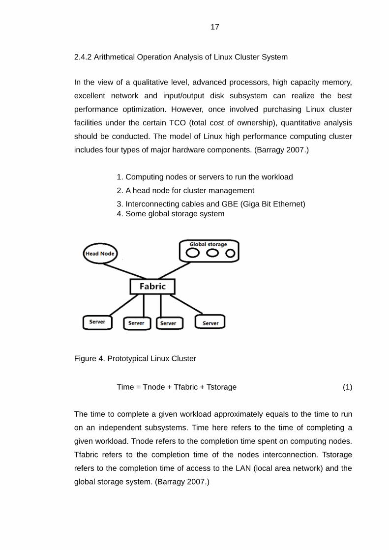
includes four types of major hardware components. (Barragy 2007.)
1. Computing nodes or servers to run the workload
2. A head node for cluster management
3. Interconnecting cables and GBE (Giga Bit Ethernet)
4. Some global storage system
Figure 4. Prototypical Linux Cluster
Time = Tnode + Tfabric + Tstorage (1)
The time to complete a given workload approximately equals to the time to run
on an independent subsystems. Time here refers to the time of completing a
given workload. Tnode refers to the completion time spent on computing nodes.
Tfabric refers to the completion time of the nodes interconnection. Tstorage
refers to the completion time of access to the LAN (local area network) and the
global storage system. (Barragy 2007.)
18
Tnode = Tcore + Tmemory (2)
The completion time on computing nodes equals to the time spent on the
independent subsystem. Tcore refers to the completion time on the computing
nodes of a microprocessor. Tmemory refers to the completion time of access to
main memory. This model is really useful for single CPU computing nodes, and
might be simply extended to symmetrical multiprocessing computing nodes.
The completion time of the subsystem associated with physical configuration
parameters of computing nodes, for example, the speed of processors, and
memory speed, can make this model more useful. (Barragy 2007.)
CPI = CPI0 + MPI * PPM (3)
CPI refers to the cycle of the processors, executing an instruction under the
workload status. CIP0 means the core of CPI. MPI here refers to the number of
errors that appear under each instruction of cache memory where workload
status is. PPM refers to the number of errors of each instruction in a unit that is
measured by the processor clock ticking. Assume the number of instructions is
P and (1 / fcore) be the processor frequency (the cycle of the processor per
second). Multiplying expression (3), expression (4) will be derived. (Barragy
2007.)
Tnode = (CPI0 * P) * (1 / fcore) + (MPI * P) * PPM * (1 / fcore) (4)
(CPI0*P) treats the running period of a processor in each task allocation
instruction as a unit. The given workload running on a microprocessor is usually
a constant named as α. It is same to (MPI*P) named as M (MBcache) that
depends on volume of memory cache when given workload and system
architecture are the constant. PPM is the cost of access to memory. Usually, the
given workload is named C. PPM, multiplied by (fcore / fbus), turns bus cycles
to processor cycles. (Barragy 2007.)
PPM=C* fcore / fbus
19
Tnode = α * (1 / fcore) + M * (1 / fbus) (5)
Tnode = α * (1 / fcore) + β (6)
These expressions demonstrate the bus frequency is a constant. Tcore = α * (1 /
fcore) and Tmemory = β = M * (1 / fbus) can be used as a conclusion. It is the
system core and bus frequencies that decide the system performance, see the
expression (5) and (6). (Barragy 2007.)
2.5 Top 500 List
The Top 500 project is the international ranking and therefore is the introduction
of the most powerful computing system. It has been published twice every year
since 1993. The ranking is released in June for the first time of every year, on
the international super-computing conference in the Germany. In November, the
second one is released at super-computing conference in the United States.
This project aims to provide with the reliable foundation to trace the
development tendency of high performance computing. (TOP500.org. 2014.)
20
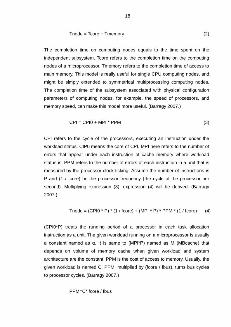
Figure 5. Top 10 Ranking (Wikimedia Foundation, Inc. 2015)
Rank in the list is ranked according to their Rmax value first, then the Rpeak
value if two machines have equal Rmax value. Rmak value is calculated by
LINPACK. The Jack Dongarra introduced the LINPACK (Linear system package)
that is a method to evaluate the performance of high performance computing.
For implementation of LINPACK, the number of processors and the cores are
also required to be listed in the ranking. The operation system normally is the
Linux system. (Wikimedia Foundation, Inc. 2015.)
21
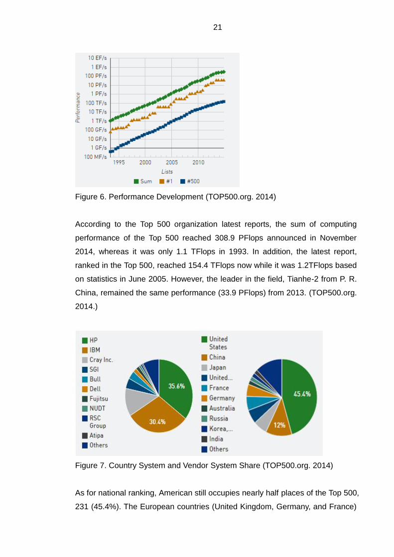
Figure 6. Performance Development (TOP500.org. 2014)
According to the Top 500 organization latest reports, the sum of computing
performance of the Top 500 reached 308.9 PFlops announced in November
2014, whereas it was only 1.1 TFlops in 1993. In addition, the latest report,
ranked in the Top 500, reached 154.4 TFlops now while it was 1.2TFlops based
on statistics in June 2005. However, the leader in the field, Tianhe-2 from P. R.
China, remained the same performance (33.9 PFlops) from 2013. (TOP500.org.
2014.)
Figure 7. Country System and Vendor System Share (TOP500.org. 2014)
As for national ranking, American still occupies nearly half places of the Top 500,
231 (45.4%). The European countries (United Kingdom, Germany, and France)
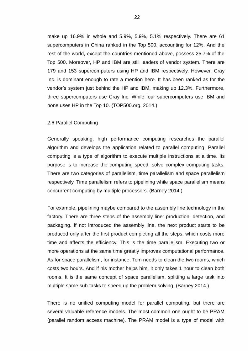
22
make up 16.9% in whole and 5.9%, 5.9%, 5.1% respectively. There are 61
supercomputers in China ranked in the Top 500, accounting for 12%. And the
rest of the world, except the countries mentioned above, possess 25.7% of the
Top 500. Moreover, HP and IBM are still leaders of vendor system. There are
179 and 153 supercomputers using HP and IBM respectively. However, Cray
Inc. is dominant enough to rate a mention here. It has been ranked as for the
vendor’s system just behind the HP and IBM, making up 12.3%. Furthermore,
three supercomputers use Cray Inc. While four supercomputers use IBM and
none uses HP in the Top 10. (TOP500.org. 2014.)
2.6 Parallel Computing
Generally speaking, high performance computing researches the parallel
algorithm and develops the application related to parallel computing. Parallel
computing is a type of algorithm to execute multiple instructions at a time. Its
purpose is to increase the computing speed, solve complex computing tasks.
There are two categories of parallelism, time parallelism and space parallelism
respectively. Time parallelism refers to pipelining while space parallelism means
concurrent computing by multiple processors. (Barney 2014.)
For example, pipelining maybe compared to the assembly line technology in the
factory. There are three steps of the assembly line: production, detection, and
packaging. If not introduced the assembly line, the next product starts to be
produced only after the first product completing all the steps, which costs more
time and affects the efficiency. This is the time parallelism. Executing two or
more operations at the same time greatly improves computational performance.
As for space parallelism, for instance, Tom needs to clean the two rooms, which
costs two hours. And if his mother helps him, it only takes 1 hour to clean both
rooms. It is the same concept of space parallelism, splitting a large task into
multiple same sub-tasks to speed up the problem solving. (Barney 2014.)
There is no unified computing model for parallel computing, but there are
several valuable reference models. The most common one ought to be PRAM
(parallel random access machine). The PRAM model is a type of model with
23
shared storage in the SIMD (single instruction stream multiple data) parallel
machine. It assumes that there are the infinite capacity of shared memory and
shared storage unit that can be accessed at any time by the processors.
However, this model is usually used for the theoretical analysis because of the
infinite capacity storage does not exist. It also ignores the impact of broadband.
(Barney 2014.)
The other model is BSP (bulk synchronous parallel) computing model that is
developed by Viliant from Harward University and Bill McColl from University of
Oxford. The BSP is carried out as a transition model, researching parallel
computing between hardware devices and applications. A parallel computer
based on BSP model, consists of a set of memory units linked by the
communication network. There are three main elements: a set of distributed
processors with local memory, global data communication network, and a
mechanism that supports global synchronization between process units. It is a
theoretical model for general architectures and scalable parallel performance
software development. (Barney 2014.)
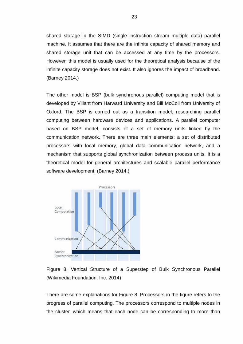
Figure 8. Vertical Structure of a Superstep of Bulk Synchronous Parallel
(Wikimedia Foundation, Inc. 2014)
There are some explanations for Figure 8. Processors in the figure refers to the
progress of parallel computing. The processors correspond to multiple nodes in
the cluster, which means that each node can be corresponding to more than
24
one processor. Additionally, local computation here is the computing performed
by a single processor. Each processor segments nodes in several separate
units for computing. It should be noted that each synchronization is also the end
of a Superstep (an iteration of the BSP algorithm) and the beginning of the next
Superstep. (Barney 2014.)
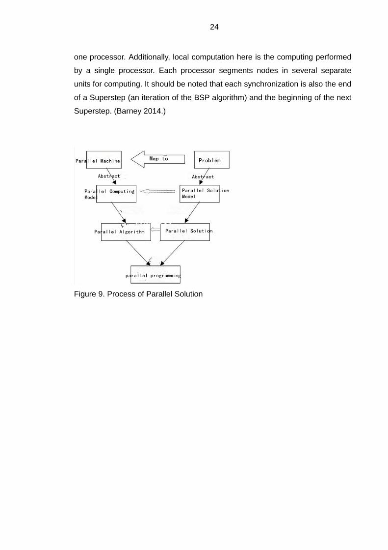
Figure 9. Process of Parallel Solution
25
3 CLOUD COMPUTING
3.1 Overview of Cloud Computing
3.1.1 Definition of Cloud Computing
Cloud computing is based on the utility and consumption of Internet services,
usually offering visualized resources with dynamic extensible performance
through the Internet. According to the definition of the National Institute of
Standards and Technology: cloud computing is based upon pay-per-use model,
allowing available and required network. It allows convenient network access to
configurable shared pool of computing resources. (Sridhar 2009.) These
resources include networks, servers, storage, applications and services. The
users can access the data center and carry out computing on demand with
remote hosts and mobile devices. The users can experience the 10 trillion times
per second computing power of cloud computing. (Lewis 2013.)
Cloud computing is the same as a huge resources spool. The cloud computing
service here can be billed like the water, electricity, gas. There are five main
benefits of cloud computing. First of all, on-demand self-services allows end
users to access computing resources and experience computing facilities
according to their needs. Such as server services and network storage as and
on demand, without additional authorization or the intervention of the system
administrator. Secondly, the service scope can be changed automatically to
adapt to dynamic change of load services. Overloading or redundancy of the
server performance, leading to decrease service quality and waste resource,
can be avoided in the cloud computing. Thirdly, all computing resources are
managed as a form of the shared resource pooling. The use of virtualization
technology, shared resources technology and resource management, are all
transparent to the end users. Fourthly, cloud computing allows universal
network access. The user can take great advantage of various terminal devices,
such as mobile phones, laptops, computers, personal digital assistants, and so
on, to access cloud computing via the Internet at any time anywhere. (Smoot-
Tan 2012, 8.)
26
Clouds can be classified as public, private, hybrid deployment models. The
public cloud usually refers to the cloud, provided by a third party provider, and is
available to the general public. It can be used via the Internet that may be free
or low-cost. A core attribute of the public cloud is shared resource services. The
private cloud is built for an individual client or company. The company or client
can manage the deployment of the application based on the infrastructure. It is
one of the most effective methods to control data traffic, data security and
service quality. Private clouds can be deployed within the firewall of the
enterprise data center, or in a safe place to host. A core attribute of a private
cloud is the resource owned. (Smoot-Tan 2012, 9.)
The hybrid cloud is a blend of the public and private cloud. In recent years, the
hybrid computing is the main model of development. (Webnotwar 2014.) For
data security reasons, companies are more willing to store data in a private
cloud. At the same time, companies expect to gain access to the public cloud
computing resources. The private cloud and public cloud maintain the distinctive
entities, but are mixed and matched by standardized or proprietary technology
in the hybrid cloud to achieve the best performance. Furthermore, the hybrid
cloud breaks through the limitations of the hardware of the private clouds. Using
the extensible ability of public cloud, the hybrid cloud can obtain higher
computing power. When enterprises transfer the non-confidential data to public
clouds, the needs and pressure of the internal private clouds can be reduced.
Moreover, the hybrid cloud can effectively reduce the cost. The enterprise
applications and data will be placed on the most appropriate platform to obtain
more interests in the combination method. (Smoot-Tan 2012, 9.)
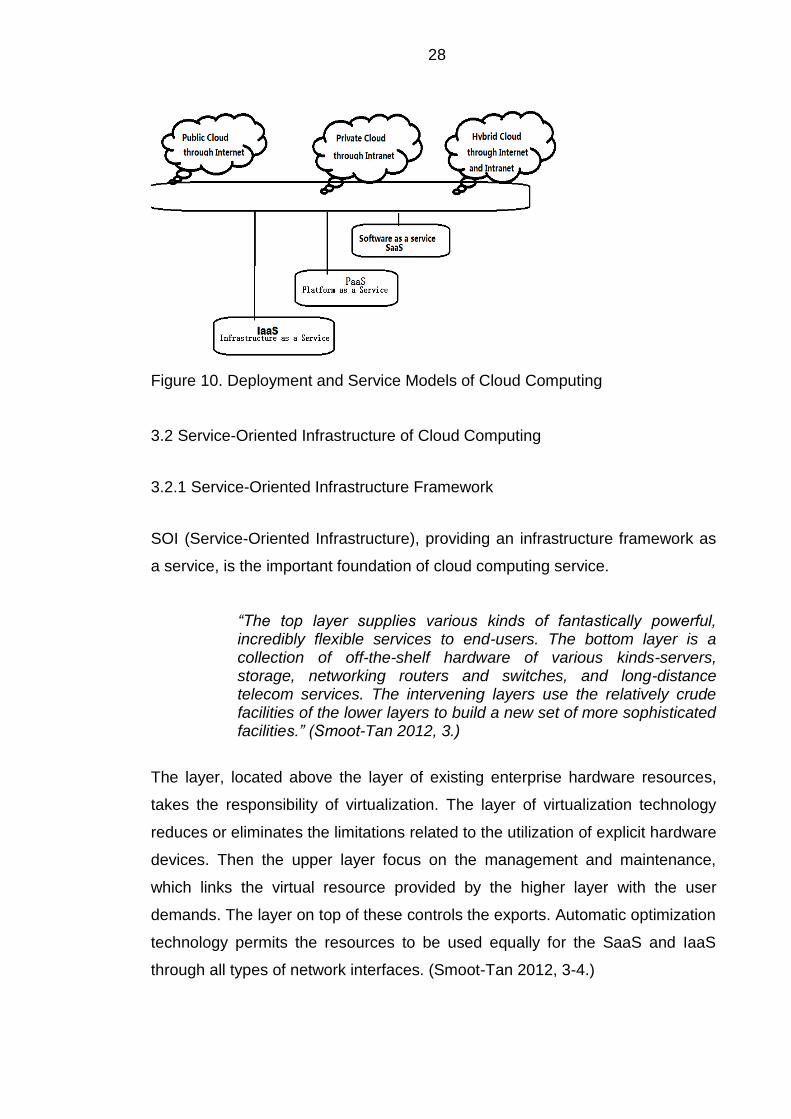
3.1.2 Service Models
Generally speaking, it is currently recognized that cloud computing is organized
into several service models: IaaS (Infrastructure as a Service), PaaS (Platform
as a Service), SaaS (Software as a service). (Webnotwar 2014.) IaaS
(Infrastructure as a Service) mainly contains computer servers, communication
devices, storage devices, and so on. The services of the infrastructure layer are
27
there to provide customers with capability of computing, storage and network
services required. Nowadays, virtualization is the core technology to develop
the IaaS. Virtualization technology can virtualize all kinds of computing devices,
storage devices, and network devices into computing resources of the virtual
resource pool. When the user places an order for these resources, the data
manager directly offers packages to the user. The Amazon EC2 service is a
typical example of the IaaS. (Smoot-Tan 2012, 10.)
PaaS (Platform as a Service) aims to provide users with a set of platforms and
the operation system applications which also cover the database application
and the server application to develop. Thus the PaaS can make a great
contribution to the development of the SaaS, and the building of enterprise
applications based on SOA (Service Oriented Architecture) model. Users do not
need to manage and maintain the cloud infrastructure that contains the network,
servers, operating systems, and storage. But, the users do not have rights to
control the application deployment. Windows Azure of Microsoft and GAE of
Google are the most popular products of the PaaS platform. (Smoot-Tan 2012,
10.)
In addition, SaaS is a type of model to offer software services through Internet
application, like Google Gmail. SaaS, using some effective technical measures,
protects data security and confidentiality of each company. SaaS takes flexible
ways to lease the service. Companies can add and delete the user account
according to requirements. At the same time, the companies pay account fees
according to the quantity and duration of the service. Due to reduced costs, the
rental cost of SaaS is lower than traditional models. The SaaS model to end
users is indistinguishable from the private enterprise built system. However, it
reduces the cost, which significantly reduces the threshold at which a company
is willing to take the investment risk. (Smoot-Tan 2012, 10-11.)
28
Figure 10. Deployment and Service Models of Cloud Computing
3.2 Service-Oriented Infrastructure of Cloud Computing
3.2.1 Service-Oriented Infrastructure Framework
SOI (Service-Oriented Infrastructure), providing an infrastructure framework as
a service, is the important foundation of cloud computing service.
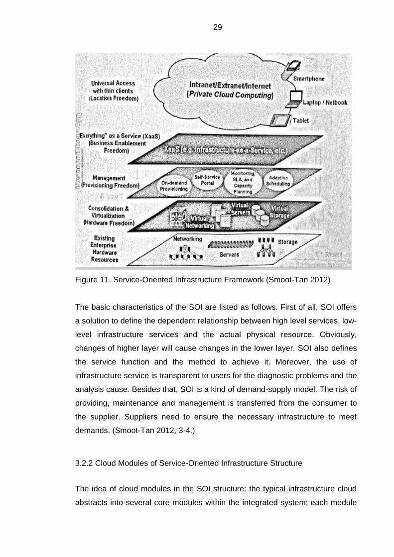
“The top layer supplies various kinds of fantastically powerful, incredibly flexible services to end-users. The bottom layer is a collection of off-the-shelf hardware of various kinds-servers, storage, networking routers and switches, and long-distance telecom services. The intervening layers use the relatively crude facilities of the lower layers to build a new set of more sophisticated facilities.” (Smoot-Tan 2012, 3.)
The layer, located above the layer of existing enterprise hardware resources,
takes the responsibility of virtualization. The layer of virtualization technology
reduces or eliminates the limitations related to the utilization of explicit hardware
devices. Then the upper layer focus on the management and maintenance,
which links the virtual resource provided by the higher layer with the user
demands. The layer on top of these controls the exports. Automatic optimization
technology permits the resources to be used equally for the SaaS and IaaS
through all types of network interfaces. (Smoot-Tan 2012, 3-4.)
29
Figure 11. Service-Oriented Infrastructure Framework (Smoot-Tan 2012)
The basic characteristics of the SOI are listed as follows. First of all, SOI offers
a solution to define the dependent relationship between high level services, low-
level infrastructure services and the actual physical resource. Obviously,
changes of higher layer will cause changes in the lower layer. SOI also defines
the service function and the method to achieve it. Moreover, the use of
infrastructure service is transparent to users for the diagnostic problems and the
analysis cause. Besides that, SOI is a kind of demand-supply model. The risk of
providing, maintenance and management is transferred from the consumer to
the supplier. Suppliers need to ensure the necessary infrastructure to meet
demands. (Smoot-Tan 2012, 3-4.)
3.2.2 Cloud Modules of Service-Oriented Infrastructure Structure
The idea of cloud modules in the SOI structure: the typical infrastructure cloud
abstracts into several core modules within the integrated system; each module
30
has clear functions and the specific interface; two modules that achieve the
same function, can replace each other as long as they follow the interface
specification of the module. A typical infrastructure cloud can be separated into
the following five subsystems: the virtualization environment subsystem, cloud
storage subsystem, the virtual network subsystem, and modules interconnected
subsystem, users and security management subsystem. (Smoot-Tan 2012, 4-5.)
The virtualization environment subsystem:
“Server virtualization supports multiple logical servers or virtual machines (VMs) on a single physical server. A VM behaves exactly like a standalone server, but it shares the hardware resources (e.g., processor, disks, network interface cards, and memory) of the physical server with the other VMs. A virtual machine monitor (VMM), often referred to as a hypervisor, makes this possible.” (Smoot-Tan 2012, 5.)
The virtualized environment subsystem uses virtualization technology to
achieve logical abstraction and unified representation of the CPU, memory,
hard drives and other physical resources. It abstracts the virtual resource that is
formed by one or more virtual machines, in order to achieve unified deployment
and management of the physical resources. Virtualized operating environment
subsystem provides four functions: resource management, node scheduling,
the virtual machine life cycle management, virtual machine monitoring. The
cluster controller is responsible for scheduling nodes, monitoring the usage
state of the virtual machine, CPU, memory and storage resource on the
monitoring platform. The node controller virtualizes physical resources which
will be allocated to virtual machines through the virtual machine controller. The
node controllers manage and monitor the virtual machines in a virtual machine
life cycle. (Marshall-McCrory-Reynolds 2006, 321-369.) The virtual machine
controller need to complete the conversion from physical resources to virtual
resources, and processes the virtual machine I / O requests. (Smoot-Tan 2012,
17-35.)
Cloud storage subsystem: The cloud storage subsystem takes responsibility of
offering the function of data storage for cloud computing. It consist of the SAN
31
(storage area network) and the storage subsystem, containing RAID, disk
arrays, and so on. (Smoot-Tan 2012, 5.) Cloud storage subsystem stores the
data for the user via two methods: based on the virtual disk of data interfaces,
based on web online storage of file or storage object. The virtual disk server is
the actual storage location for the virtual disk. A local virtual disk is mapped to
disk device on a physical node through storage network transport protocol (FC-
SAN (Fiber Channel Storage Area Network), iSCSI (Internet Small Computer
System Interface), AoE (Advanced Technology Attachment over Ethernet) etc.).
The virtual disk management controller is mapped the disk device on that node
to disk on virtual machine (through storage virtualization from storage space of
the virtual disk server). (Smoot-Tan 2012, 35-40.)
In the organization of online storage systems, buckets and objects, the buckets
correspond to the file system directory. The objects correspond to the file in the
file system. Online storage systems allow users to create, delete, upload,
download, and delete files. The online storage systems also provide another
mechanism to facilitate data flow in the user management storage system.
Firstly, the online storage system receives the storage resource request from
the user and other subsystems. Then the file storage system will handle and
store files required by the user or other subsystems according to the
established method and process, such as encryption, decryption, restructuring.
It is convenient for users, administrators, and other subsystem to operate a
large number of documents in the file storage system by using metadata
storage. (Smoot-Tan 2012, 6-7.)
The virtual network subsystem: virtual network subsystem mainly solves the
problem of virtual machines interconnection. Unlike physical machines making
up a complex logical physical network, the network of virtual machine is simple
to configure. The virtual network subsystem offers four core functions:
1. Configure the communication between the virtual network and
virtual machine
2. Define security groups, running virtual machines in the same
group with the same rules, such as ping, ssh
32
3. Achieve flexibility IP functionality, allowing users to set up a
virtual machine IP
4. Achieve network isolation, the isolation of network traffic between
different security groups (Smoot-Tan 2012, 6-7)
It is worthy to be noticed that isolation, to some extent, ought to be applied to
each end-user and computing resource. Thus, one of the core necessities is to
set up separate logical traffic paths based on a shared physical network
infrastructure. Virtualization of the IP layer supplies end-to-end network
segmentation and separate connections for end users. Network virtualization
will be achieved by VRF (virtual routing forwarding) and MPLS (multi-protocol
label switching) technology. The principle of network virtualization is the logical
separation of company physical network infrastructure into different isolated
sub-networks. However, these sub-networks cannot be recognized the
distinction of the physical network by the end users. (Smoot-Tan 2012, 6.)
Modules interconnection subsystem plays different roles of different modules
and subsystems in cloud systems. Modules interconnected subsystems are
responsible for the exchange information through the subsystem
interconnection. First of all, interconnection and integration with other
subsystems constitute a complete cloud infrastructure. Secondly, the
subsystem interconnection module ensures to keep balance with user access
and client load balancing. At last, the subsystem interconnection module
supplies several channels of information flow and control flow in the entire
infrastructure cloud system. A typical cloud infrastructure provides two user-
level access interfaces, the front end of infrastructure cloud interface and web-
based online storage system interface. The former is responsible for receiving
and processing requested services for other users, recording the information
needed by running the whole system. The latter receives, processes and
responds to web-based online storage service request that the user submitted.
(Smoot-Tan 2012, 8-9.)
User and security management subsystem:
33
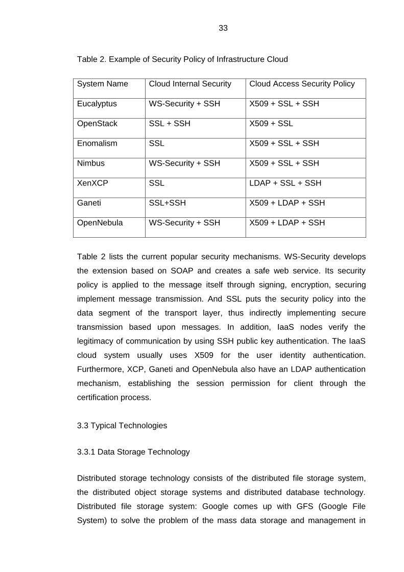
Table 2. Example of Security Policy of Infrastructure Cloud
System Name Cloud Internal Security Cloud Access Security Policy
Eucalyptus WS-Security + SSH X509 + SSL + SSH
OpenStack SSL + SSH X509 + SSL
Enomalism SSL X509 + SSL + SSH
Nimbus WS-Security + SSH X509 + SSL + SSH
XenXCP SSL LDAP + SSL + SSH
Ganeti SSL+SSH X509 + LDAP + SSH
OpenNebula WS-Security + SSH X509 + LDAP + SSH
Table 2 lists the current popular security mechanisms. WS-Security develops
the extension based on SOAP and creates a safe web service. Its security
policy is applied to the message itself through signing, encryption, securing
implement message transmission. And SSL puts the security policy into the
data segment of the transport layer, thus indirectly implementing secure
transmission based upon messages. In addition, IaaS nodes verify the
legitimacy of communication by using SSH public key authentication. The IaaS
cloud system usually uses X509 for the user identity authentication.
Furthermore, XCP, Ganeti and OpenNebula also have an LDAP authentication
mechanism, establishing the session permission for client through the
certification process.
3.3 Typical Technologies
3.3.1 Data Storage Technology
Distributed storage technology consists of the distributed file storage system,
the distributed object storage systems and distributed database technology.
Distributed file storage system: Google comes up with GFS (Google File
System) to solve the problem of the mass data storage and management in
34
systems. The object storage system is an extension of the traditional block
device with added intelligent functions. The higher layers access the object via
object ID, instead of knowing the specific space distribution of the object. The
S3 system of Amazon can be classified into the object storage technology.
Under the cloud computing environment, most applications do not require the
full SQL statement but need query statements as a form of Key-Value. BigTable
of Google belongs to the data storage service type. (Leng-Wang 2012, 863-866.)
Cloud computing systems store the data by using distributed technology, and
guarantee the availability by using redundant storage, guaranteeing the
practicality and economic efficiency. Furthermore, cloud computing should meet
the requirements of great many users and serve customers, which leads to the
data storage technology having higher throughput and transmission rate. Future
development of data storage technology will focus on cloud computing large
scale data storage, data encryption, security assurance and improvement of I/O
rates. (Song-Wu-Yao 2011, 320-324.)
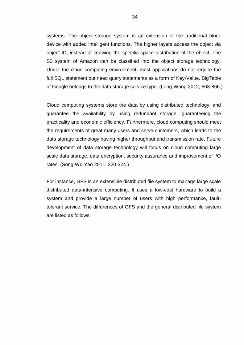
For instance, GFS is an extensible distributed file system to manage large scale
distributed data-intensive computing. It uses a low-cost hardware to build a
system and provide a large number of users with high performance, fault-
tolerant service. The differences of GFS and the general distributed file system
are listed as follows:
35
Table 3. Differences of Google File System and the General Distributed File
System
File System Component Failure
Management
File Size Data Flow And Control
Flow
GFS Not Exception
Handling
A Few
Large
Files
Separate
Traditional
Distributed
File System
Exception Handling Lots Of
Small
Files
Combine
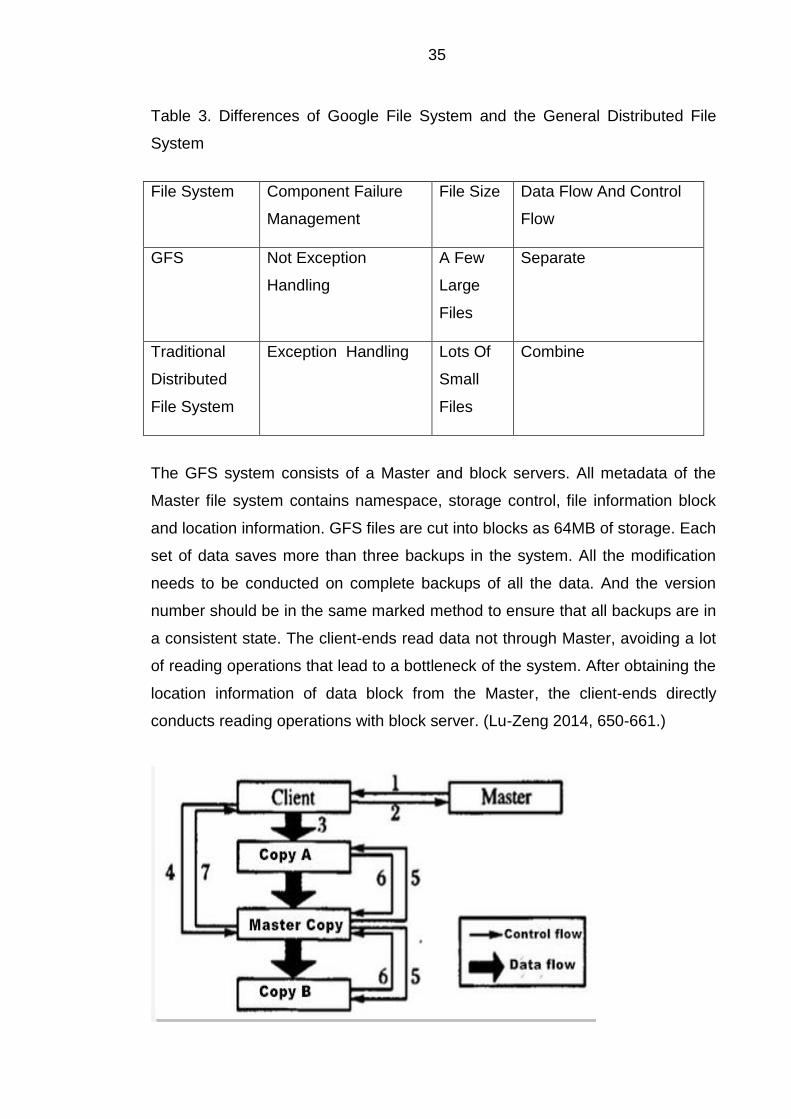
The GFS system consists of a Master and block servers. All metadata of the
Master file system contains namespace, storage control, file information block
and location information. GFS files are cut into blocks as 64MB of storage. Each
set of data saves more than three backups in the system. All the modification
needs to be conducted on complete backups of all the data. And the version
number should be in the same marked method to ensure that all backups are in
a consistent state. The client-ends read data not through Master, avoiding a lot
of reading operations that lead to a bottleneck of the system. After obtaining the
location information of data block from the Master, the client-ends directly
conducts reading operations with block server. (Lu-Zeng 2014, 650-661.)
36
Figure 12. The Control Flow and the Data Flow
The control flow and data flow are separate, as shown in Figure 11 above. After
gaining the written authorization from the Master, the client-ends transmits the
data to all copies of the data. The client can issue a write request control signal
after all the data copies receiving modified data. After all the data copies
finishing the update, the master copy issues a control signal of written operation
completed to the client-ends. (Lu-zeng 2014, 650-661.)
3.3.2 Distributed Programming Technology
The programming model of the cloud must be simple. And the programming
model should be transparent to the users and programmers for parallel
computing and task scheduling. It offers easier computing services to users with
a specific purpose. Generally, cloud computing uses MAP-Reduce
programming model. Almost all IT vendors that employ a programming model is
based on the idea of MAP-Reduce programming. MAP-Reduce is not just a
programming model, but also a high-efficiency task scheduling model. And
Map-Reduce programming model is not only suitable for cloud computing, but
also suitable for the multi-core processors and clusters. (Yang-Zhao 2014,
2867-2870.)
Map-Reduce is a programming model for processing and generating mass data
sets. Programmers specify the sub-block data processing in the Map function.
And programmers also specify how to process intermediate results of sub-block
data in the Reduction function. Running the Map-Reduce programs on a cluster,
programmers need not focus on the input, distribution and scheduling of data.
The cluster system also manages communication and fault handling between
nodes. Users only need to specify the Map function and the Reduce function to
write distributed parallel programs. (Chen-Hu-Huang-Zhu 2012, 1-4.)
There are five steps to execute a Map-Reduce program: input file, the file will be
assigned to several workers to execute in parallel, writing intermediate files,
multiple workers running at the same time and output. Writing intermediate files
37
locally reduces the pressure on network bandwidth and time cost. When
executing Reduce function, the system will send Reduce request to the node of
intermediate file, reducing the bandwidth needs to transfer the intermediate file.
(Chen-Hu-Huang-Zhu 2012, 1-4.)
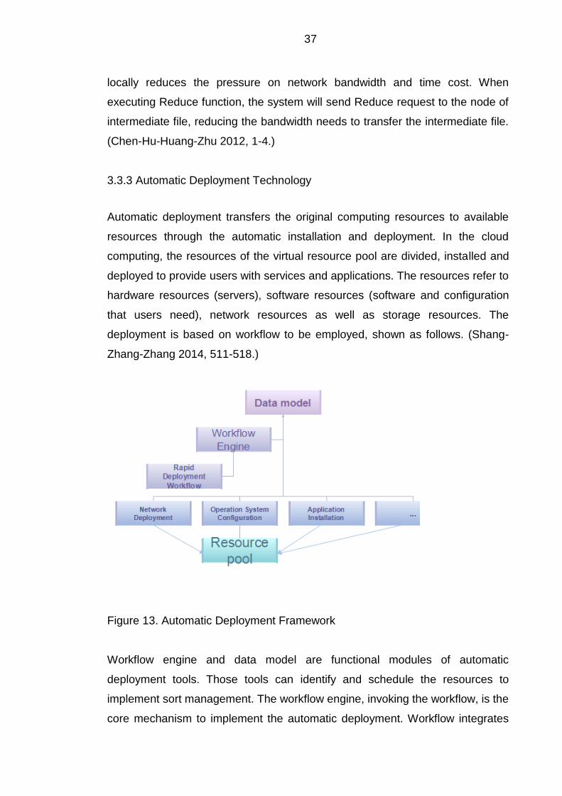
3.3.3 Automatic Deployment Technology
Automatic deployment transfers the original computing resources to available
resources through the automatic installation and deployment. In the cloud
computing, the resources of the virtual resource pool are divided, installed and
deployed to provide users with services and applications. The resources refer to
hardware resources (servers), software resources (software and configuration
that users need), network resources as well as storage resources. The
deployment is based on workflow to be employed, shown as follows. (Shang-
Zhang-Zhang 2014, 511-518.)
Figure 13. Automatic Deployment Framework
Workflow engine and data model are functional modules of automatic
deployment tools. Those tools can identify and schedule the resources to
implement sort management. The workflow engine, invoking the workflow, is the
core mechanism to implement the automatic deployment. Workflow integrates
38
different types of scripts in a centralized, reusable database. These workflows
can automatically complete configuration of operating systems, applications,
and network devices. (Shang-Zhang-Zhang 2014, 511-518.)
3.4 Case Study
3.4.1 Cloud Computing to E-Commerce
E-commerce can offer a pleasant shopping experience at a reasonable price to
customers. However, the servers will become congested, or even crash when
many users log in simultaneously. The enterprise should have sufficient
computing capacity and storage capacity to face the situation. Thus, advanced
devices of software and hardware are needed to support the enterprise.
However, it is very difficult for small and medium sized enterprises to develop
their own hardware and software devices. (Wang 2013, 313-318.)
Firstly, developing their own software and hardware requires a big investment,
including development cost, maintenance cost and the cost of license of
software. Secondly, it takes a long time to develop, investigate and test new
software. The earning cycle maybe too long for a return on the cost of the
investment. Thirdly, professional talents are lacked. Software development,
network maintenance and database process require abundant professional
talents. (Wang 2013, 313-318.)
Cloud computing offers a great solution to those problems. The pay-per-use
model of the cloud computing is popular for e-commerce service that is
designed for small and medium-sized enterprises. The small and medium-sized
enterprises can extend the computing sources, according to their business
requirements. The use of the cloud computing for the enterprises can greatly
avoid resources redundancy and waste. Moreover, online shopping platform
based on a cloud computing system can collect the application services of
various fields. The cloud computing not only is able to solve the problem of
processing data, but also provides with integration services, drawing the
attention of e-commerce enterprises. (Wang 2013, 313-318.)
39
In addition, cloud computing allows more enterprises to implement the business
model of e-commerce service. The investment of the e-commerce can be
adjusted according to change of the volume of business. Also, cloud computing
offers more professional services that are developed by the information
technology companies than the services designed by the business companies
themselves. (Wang 2013, 313-318.)
There are also some problems existing for cloud computing technology. For
example, security management of the cloud computing should be enhanced.
The framework of the cloud computing systems has some security flaws,
resulting in the increase of the risk of the accessing without authorization and
stealing information. The legal systems (laws) related need to be also
established to protect information security for users and companies.
Furthermore, the rate of return and applicability should be also improved.
(Wang 2013, 313-318.)
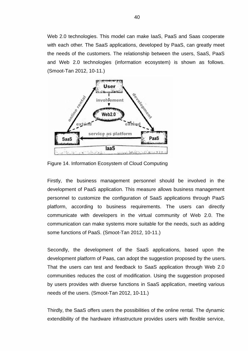
3.4.2 Information Ecosystem of Cloud Computing
The development of informatization should be the integration of cloud
computing and Web 2.0 technologies.
“Web 2.0 describes World Wide Web sites that emphasize user-generated content, usability, and interoperability. A Web 2.0 site may allow users to interact and collaborate with each other in a social media dialogue as creators of user-generated content in a virtual community, in contrast to Web sites where people are limited to the passive viewing of content. ” (Wikimedia Foundation, Inc. 2015.)
This kind of integration reaches to higher level of cloud computing
informatization, called as people services. Cloud computing informatization is
created and used by system developers as well as users under the concepts of
Web 2.0 technologies. The system developers and users work together to
create a more valuable system. Thus, one of building informatization models is
the user involvement to build an informatization system under the concepts of
40
Web 2.0 technologies. This model can make IaaS, PaaS and Saas cooperate
with each other. The SaaS applications, developed by PaaS, can greatly meet
the needs of the customers. The relationship between the users, SaaS, PaaS
and Web 2.0 technologies (information ecosystem) is shown as follows.
(Smoot-Tan 2012, 10-11.)
Figure 14. Information Ecosystem of Cloud Computing
Firstly, the business management personnel should be involved in the
development of PaaS application. This measure allows business management
personnel to customize the configuration of SaaS applications through PaaS
platform, according to business requirements. The users can directly
communicate with developers in the virtual community of Web 2.0. The
communication can make systems more suitable for the needs, such as adding
some functions of PaaS. (Smoot-Tan 2012, 10-11.)
Secondly, the development of the SaaS applications, based upon the
development platform of Paas, can adopt the suggestion proposed by the users.
That the users can test and feedback to SaaS application through Web 2.0
communities reduces the cost of modification. Using the suggestion proposed
by users provides with diverse functions in SaaS application, meeting various
needs of the users. (Smoot-Tan 2012, 10-11.)
Thirdly, the SaaS offers users the possibilities of the online rental. The dynamic
extendibility of the hardware infrastructure provides users with flexible service,

41
allowing users to increase usage according to the change of business. In
addition, all the operations of customized PaaS and its extendable applications
are achieved by information shared between users, developers, and vendors of
SaaS. (Smoot-Tan 2012, 10-11.)
42
4 HIGH PERFORMANCE COMPUTING APPLIED TO CLOUD COMPUTING
4.1 Comparison Application Profile of Cloud Computing and High Performance
Computing
The application of cloud computing should possess several features:
1. The applications are not the parallel applications, or the thread
applications.
2. Almost all applications do not require too much memory
bandwidth and CPU usage.
3. The applications rarely execute I/O (input/ output) instructions of
computing.
4. The applications can repair itself. In other words, once the
failures showing in the applications for any reasons, it can easily
restart, not affecting the end-user. (H3C Technologies Co. 2015.)
The application of high performance computing should possess several
features:
1. Many applications of high performance computing are the serial
applications. There are some kinds of data communication between
various processes of the application.
2. Sometimes, the number of transmission data between various
processes is small.
3. Sometimes, the number of transmission data between various
processes is large.
4. Some applications are the serial applications and thread
applications, running on a single node. For example: BLAST (Bell
Labs Layered Space time).
5. Some serial applications and parallel applications are able to
execute many IO tasks. For example: Ansys, Abaqus or Nastran
FEA codes, etc.
6. Some applications can generate a checkpoint that is a snapshot
of the calculation process. Once failures showing in the applications
for any reasons, it can restart from the last checkpoint, without
43
having to restart from the beginning. But, not all applications have
this feature. (H3C Technologies Co. 2015.)
The cloud computing applications and high performance applications seem to
be totally different from each other. However, there are still some common
features between the cloud computing applications and high performance
applications. For example, the BLAST, an application of high performance
computing, is independent of interconnection and communication of the nodes.
It also does not require to execute many IO instructions. Those special features
are greatly suitable for the cloud computing. It is hard to find such specific
applications since the parallel applications can completely run on a single node.
As long as the data set can be placed in the nodes without switching, the
applications are able to run in a cloud computing environment. (H3C
Technologies Co. 2015.)
There are some necessary features of high performance computing to ensure
the normal operation for the applications and data sets in the cloud computing
environment. Firstly, the high performance computing application must run on a
single node and its data set must be located on a single node. Secondly, the
high performance computing application must be non-IO intensive. Thirdly, the
high performance computing application needs to run fast and can create a
checkpoint to solve the system failure. (H3C Technologies Co. 2015.)
4.2 High Performance Computing Deployments in Cloud Computing
Environments
The high performance computing can be a kind of special services of the cloud
computing to provide computing service to the Internet Users. Thus, the high
performance computing can be treated as a portion of the data center of the
cloud computing. But the high performance computing is still very different from
the cloud computing. The specific requirements of network and security features
are listed as follows. The high performance computing is a special application of
the server cluster. This application requires the server being a system, showing
in as follows. (H3C Technologies Co. 2015.)
44
Firstly, the isomerism cannot be in the high performance computing cluster
system. Secondly, the requirements of communication service quality within the
high performance computing cluster is very and strict. Therefore, the system
cannot share the business service channel with others. Thirdly, the security
level of the high performance computing cluster is very high. It requires logical
and physical separation with other systems, from the access area to the
computing area. Fourthly, normally, the virtual machine does not exist. Thus,
there are not so busy for the communication flow within the high performance
computing cluster. At last, the performance of computing nodes needs to be
excellent to meet the requirements. (H3C Technologies Co. 2015.)
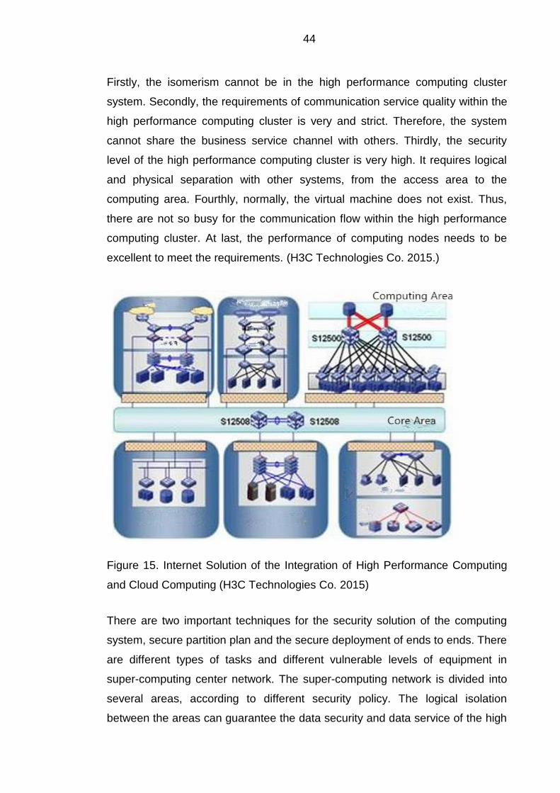
Figure 15. Internet Solution of the Integration of High Performance Computing
and Cloud Computing (H3C Technologies Co. 2015)
There are two important techniques for the security solution of the computing
system, secure partition plan and the secure deployment of ends to ends. There
are different types of tasks and different vulnerable levels of equipment in
super-computing center network. The super-computing network is divided into
several areas, according to different security policy. The logical isolation
between the areas can guarantee the data security and data service of the high
45
performance computing area. Moreover, security deployment between the ends
to ends can maintain the logical isolation, from the access to the super-
computing center, for various users. The isolation of ends to ends can further
strengthen the security of data center and service quality. (H3C Technologies
Co. 2015.)
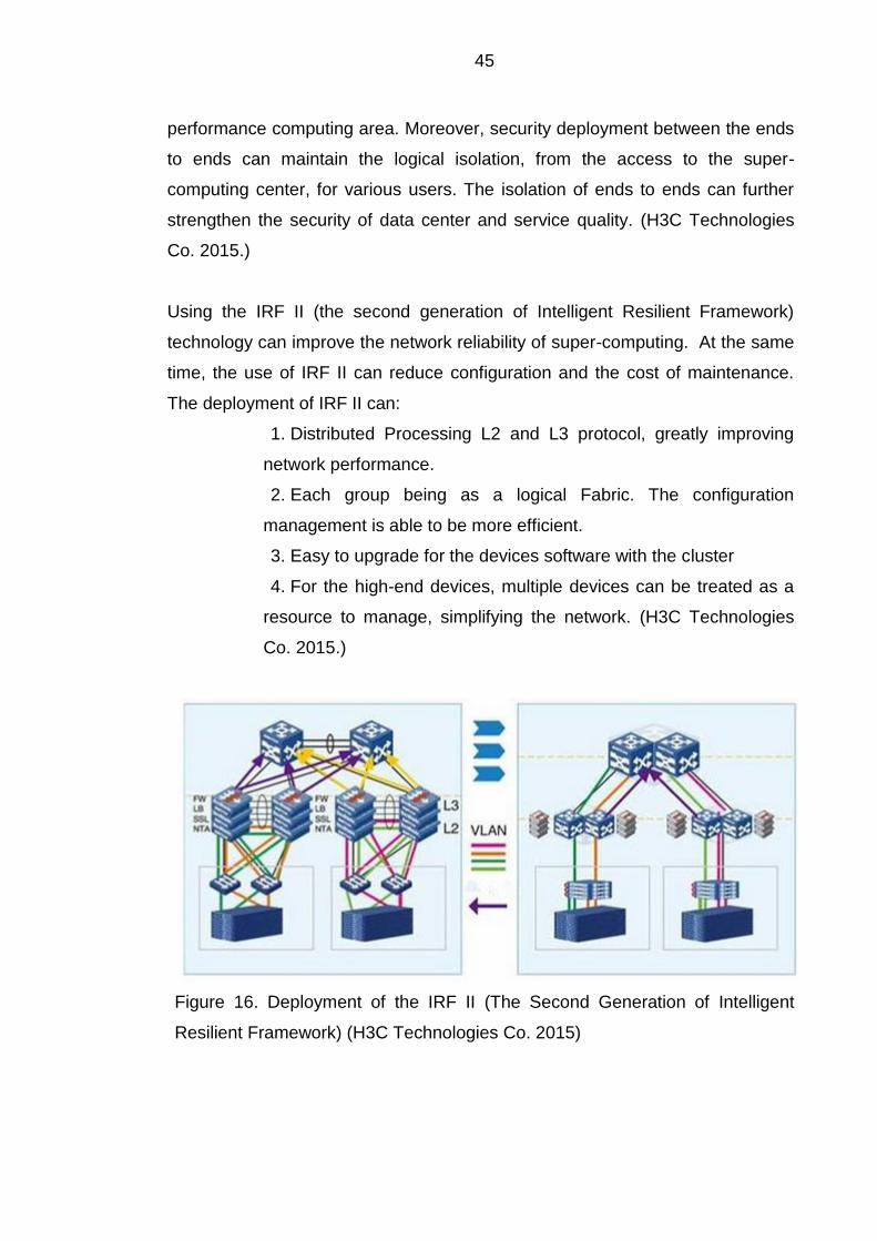
Using the IRF II (the second generation of Intelligent Resilient Framework)
technology can improve the network reliability of super-computing. At the same
time, the use of IRF II can reduce configuration and the cost of maintenance.
The deployment of IRF II can:
1. Distributed Processing L2 and L3 protocol, greatly improving
network performance.
2. Each group being as a logical Fabric. The configuration
management is able to be more efficient.
3. Easy to upgrade for the devices software with the cluster
4. For the high-end devices, multiple devices can be treated as a
resource to manage, simplifying the network. (H3C Technologies
Co. 2015.)
Figure 16. Deployment of the IRF II (The Second Generation of Intelligent
Resilient Framework) (H3C Technologies Co. 2015)
46
5 CONCLUSION
This thesis report provides basic knowledge of high performance computing and
cloud computing. The feature, high speed computing capacity, can be used to
process big data and complicated information. Cloud computing is based upon
pay-per-use model, offering visualized resources through Internet service. The
idea of integration of the high performance computing and cloud computing
comes up for better computing service.
In the thesis, the author compares the application profile of the cloud computing
and the high performance computing. After researching, there are still some
common features that are important breakthrough for development in the future.
Because of the limitations of time and resources, there are several shortages in
the thesis. For example, the language expression is not exact. Also, the other
super-computing should be researched later.
47
REFERENCES
Barney, B. 2014. Introduction to Parallel Computing. Referenced 13 April 2015. https://computing.llnl.gov/tutorials/parallel_comp/.
Buyya, R. 1999. High Performance Cluster Computing. Referenced 18 March 2015. http://dpnm.postech.ac.kr/cluster/ppt/Cluster-Tutorial/.
Barragy, Ted. 2007. What Drives Performance in HPC? Referenced 13 April
2015. http://www.linux-mag.com/id/4170/.
E-sciencecity. 2015. Computer and supercomputer. Referenced 18 Marchss
2015. http://www.e-sciencecity.org/EN/HPC-tower/history-of-supercomputing.html
Gerber, R. 2012. Introduction to High Performance Computers. Referenced 20 March 2015. https://www.nersc.gov/assets/pubs_presos/IntroHPCSystems-NewUser.pdf/
Hu, T-Chen, H-Huang, L-Zhu, X. A survey of mass data mining based on cloud
computing. IEEE. 1-4.
H3C Technologies Co. 2015. High Performance Computing Applied to Cloud Computing. Referenced 18 April 2015. http://www.h3c.com/portal/.
Jacob, Matthew. 2015. High Performance Computing. Referenced 07 April
2015. http://nptel.ac.in/courses/106108055/module5/HPC%20Lecture22.pdf.
Jones, M. D. 2011. Introduction to High Performance Computers. Referenced
20 March 2015. http://www.buffalo.edu/content/www/ccr/support/trainingresources/tutorials/advanced-topics--e-g--mpi--gpgpu--openmp--etc--/2011-01---introduction-to-hpc--hpc-1-/_jcr_content/par/download/file.res/introHPC-handout-2x2.pdf.
Kalcher, S. 2007. Don’t forget the “Fabric”. Referenced 07 April 2015.
http://www.adtechglobal.com/Data/Sites/1/marketing/dont-forget-the-fabricreport.pdf?hsCtaTracking=c2d60212f29d4cf0a2a5192034a471ff%7Cc356f717-0955-4197-a25a-cd07e644d9c4
Kohlmeyer, A. 2010. Introduction to High-Performance Computing. Referenced
20 March 2015. http://portal.ictp.it/icts/hpc-appointments/HPC-Appointment-3.pdf.
Leng, L-Wang, L. 2012. Research on cloud computing and key technologies.
IEEE. 863-866.
48
Lewis, G. 2013. Standards in Cloud Computing Interoperability. Referenced 15 April 2015. http://blog.sei.cmu.edu/post.cfm/standards-in-cloud-computing interoperability.
Lu, G-Z, W. 2014. Cloud Computing Survey. Applied Mechanics and Materials,
Volume 530-531. 650-661. Marshall, D-McCrory, D-Reynolds, W. 2006. Advanced Server Virtualization:
VMware and Microsoft Platforms in the Virtual Data Center. Publications: Auerbach
Shang, Y-Zhang, R-Zhang, S. 2014. An Automatic Deployment Mechanism on Cloud Computing Platform. IEEE. 511-518. Smoot, S-Tan, N. 2011. Private Cloud Computing, 1st Edition: Consolidation,
Virtualization, and Service-Oriented Infrastructure. Sridhar. T. Cloud Computing - A Primer. Referenced 13 April 2015.
http://www.cisco.com/web/about/ac123/ac147/archived_issues/ipj_12 3/123_cloud1.html.
Song, J-Wu, C-Yao, J. 2011. Cloud computing and its key techniques. IEEE.
320-324. Top 500. 2014. The list of top 500. Referenced 15 April 2015.
http://www.top500.org/ Wang, D. 2013. Influences of Cloud Computing on E-Commerce Businesses and Industry. Journal of Software Engineering and Applications. Volume 6. 313-318. Webnotwar. 2015. Clearing the cloud mistakes misconceptionsand misuses
with cloud computing. Referenced 15 April 2015. http://www.webnotwar.ca/clearing-the-cloud-mistakes-misconceptions-and-misuses-with-cloud-computing/.
Zhao, X-Yang, C. 2014. Design of Cloud Computing Environment for Online Open Course. Applied Mechanics and Materials, Volume 687-691. 2867- 2870.