High- Lift Devices B - 2: Mach - Number Effects & Lift ...
10
AE317 Aircraft Flight Mechanics & Performance UNIT B: Wings and Airplanes ROAD MAP . . . B - 1: Wings, H - L Devices, & Whole Aircraft B - 2: Mach - Number Effects & Lift/Drag B - 3: Advanced Subjects & An Exercise Brandt, et.al., Introduction to Aeronautics: A Design Perspective Chapter 4: Wings and Airplanes 4.1 Design Motivation 4.2 Wings 4.3 High - Lift Devices 4.4 Whole Aircraft Lift 4.5 Whole Aircraft Drag and Drag Polar Unit B - 1: List of Subjects Wing Geometry Wing Tip Vortices & Downwash Induced Drag Winglets & Tip Plates High - Lift Devices
Transcript of High- Lift Devices B - 2: Mach - Number Effects & Lift ...
AE317 Aircraft Flight Mechanics & Performance
UNIT B: Wings and Airplanes
ROAD MAP . . .
B-1: Wings, H-L Devices, & Whole Aircraft
B-2: Mach-Number Effects & Lift/Drag
B-3: Advanced Subjects & An Exercise
Brandt, et.al., Introduction to Aeronautics: A Design Perspective
Chapter 4: Wings and Airplanes
4.1 Design Motivation4.2 Wings4.3 High-Lift Devices4.4 Whole Aircraft Lift4.5 Whole Aircraft Drag and Drag Polar
Unit B-1: List of Subjects
Wing Geometry
Wing Tip Vortices & Downwash
Induced Drag
Winglets & Tip Plates
High-Lift Devices
Page 2 of 10 Unit B-1
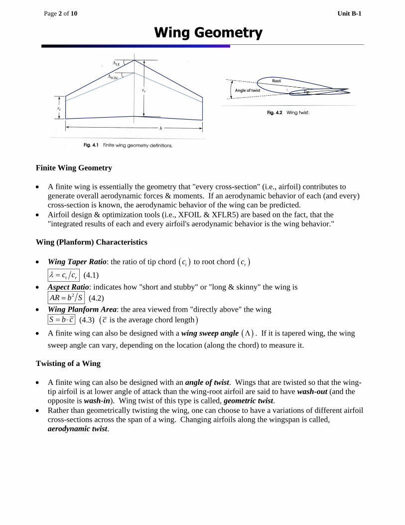
Finite Wing Geometry
• A finite wing is essentially the geometry that "every cross-section" (i.e., airfoil) contributes to
generate overall aerodynamic forces & moments. If an aerodynamic behavior of each (and every)
cross-section is known, the aerodynamic behavior of the wing can be predicted.
• Airfoil design & optimization tools (i.e., XFOIL & XFLR5) are based on the fact, that the
"integrated results of each and every airfoil's aerodynamic behavior is the wing behavior."
Wing (Planform) Characteristics
• Wing Taper Ratio: the ratio of tip chord ( )tc to root chord ( )rc
t rc c = (4.1)
• Aspect Ratio: indicates how "short and stubby" or "long & skinny" the wing is 2AR b S= (4.2)
• Wing Planform Area: the area viewed from "directly above" the wing
S b c= (4.3) ( ) is the average chord lengthc
• A finite wing can also be designed with a wing sweep angle ( ) . If it is tapered wing, the wing
sweep angle can vary, depending on the location (along the chord) to measure it.
Twisting of a Wing
• A finite wing can also be designed with an angle of twist. Wings that are twisted so that the wing-
tip airfoil is at lower angle of attack than the wing-root airfoil are said to have wash-out (and the
opposite is wash-in). Wing twist of this type is called, geometric twist.
• Rather than geometrically twisting the wing, one can choose to have a variations of different airfoil
cross-sections across the span of a wing. Changing airfoils along the wingspan is called,
aerodynamic twist.
Wing Geometry
Page 3 of 10 Unit B-1
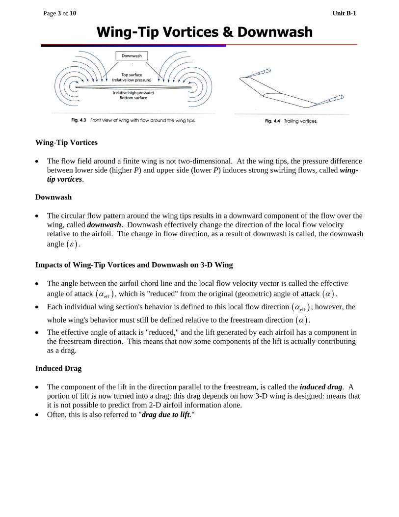
Wing-Tip Vortices
• The flow field around a finite wing is not two-dimensional. At the wing tips, the pressure difference
between lower side (higher P) and upper side (lower P) induces strong swirling flows, called wing-
tip vortices.
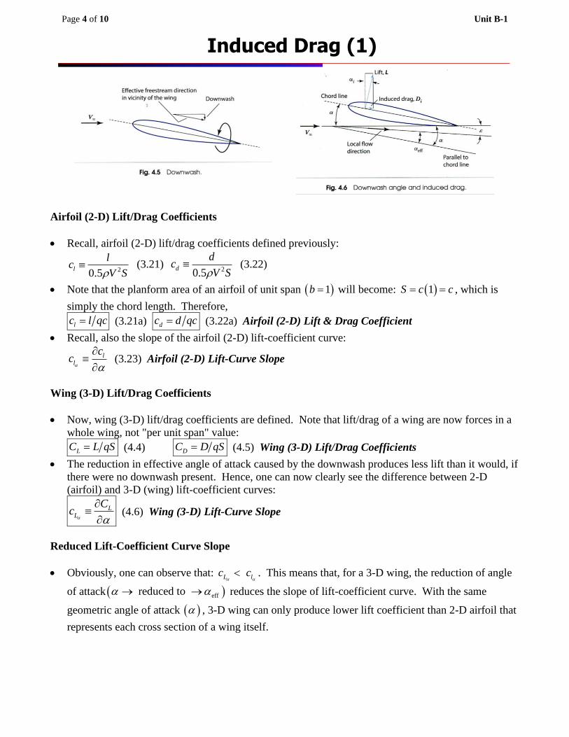
Downwash
• The circular flow pattern around the wing tips results in a downward component of the flow over the
wing, called downwash. Downwash effectively change the direction of the local flow velocity
relative to the airfoil. The change in flow direction, as a result of downwash is called, the downwash
angle ( ) .
Impacts of Wing-Tip Vortices and Downwash on 3-D Wing
• The angle between the airfoil chord line and the local flow velocity vector is called the effective
angle of attack ( )eff , which is "reduced" from the original (geometric) angle of attack ( ) .
• Each individual wing section's behavior is defined to this local flow direction ( )eff ; however, the
whole wing's behavior must still be defined relative to the freestream direction ( ) .
• The effective angle of attack is "reduced," and the lift generated by each airfoil has a component in
the freestream direction. This means that now some components of the lift is actually contributing
as a drag.
Induced Drag
• The component of the lift in the direction parallel to the freestream, is called the induced drag. A
portion of lift is now turned into a drag: this drag depends on how 3-D wing is designed: means that
it is not possible to predict from 2-D airfoil information alone.
• Often, this is also referred to "drag due to lift."
Wing-Tip Vortices & Downwash
Page 4 of 10 Unit B-1
Airfoil (2-D) Lift/Drag Coefficients
• Recall, airfoil (2-D) lift/drag coefficients defined previously:
20.5l
lc
V S (3.21)
20.5d
dc
V S (3.22)
• Note that the planform area of an airfoil of unit span ( )1b = will become: ( )1S c c= = , which is
simply the chord length. Therefore,
lc l qc= (3.21a) dc d qc= (3.22a) Airfoil (2-D) Lift & Drag Coefficient
• Recall, also the slope of the airfoil (2-D) lift-coefficient curve:
ll
cc
(3.23) Airfoil (2-D) Lift-Curve Slope
Wing (3-D) Lift/Drag Coefficients
• Now, wing (3-D) lift/drag coefficients are defined. Note that lift/drag of a wing are now forces in a
whole wing, not "per unit span" value:
LC L qS= (4.4) DC D qS= (4.5) Wing (3-D) Lift/Drag Coefficients
• The reduction in effective angle of attack caused by the downwash produces less lift than it would, if
there were no downwash present. Hence, one can now clearly see the difference between 2-D
(airfoil) and 3-D (wing) lift-coefficient curves:
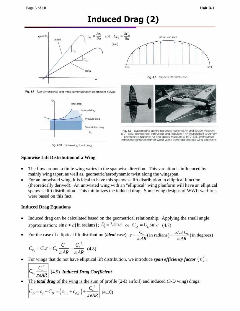
LL
Cc
(4.6) Wing (3-D) Lift-Curve Slope
Reduced Lift-Coefficient Curve Slope
• Obviously, one can observe that: L lc c . This means that, for a 3-D wing, the reduction of angle
of attack ( )eff reduced to → → reduces the slope of lift-coefficient curve. With the same
geometric angle of attack ( ) , 3-D wing can only produce lower lift coefficient than 2-D airfoil that
represents each cross section of a wing itself.
Induced Drag (1)
Page 5 of 10 Unit B-1
Spanwise Lift Distribution of a Wing
• The flow around a finite wing varies in the spanwise direction. This variation is influenced by
mainly wing taper, as well as, geometric/aerodynamic twist along the wingspan.
• For an untwisted wing, it is ideal to have this spanwise lift distribution in elliptical function
(theoretically derived). An untwisted wing with an "elliptical" wing planform will have an elliptical
spanwise lift distribution. This minimizes the induced drag. Some wing designs of WWII warbirds
were based on this fact.
Induced Drag Equations
• Induced drag can be calculated based on the geometrical relationship. Applying the small angle
approximation: ( )sin in radians : siniD L = or siniD LC C = (4.7)
• For the case of elliptical lift distribution (ideal case): ( ) ( )57.3
in radians in degreesL LC C
AR AR
= =
2
i
L LD L L
C CC C C
AR AR
= = = (4.8)
• For wings that do not have elliptical lift distribution, we introduce span efficiency factor ( )e :
2
i
LD
CC
eAR (4.9) Induced Drag Coefficient
• The total drag of the wing is the sum of profile (2-D airfoil) and induced (3-D wing) drags:
( )2
, ,i
LD d D d p d f
CC c C c c
eAR= + = + + (4.10)
Induced Drag (2)
Page 6 of 10 Unit B-1
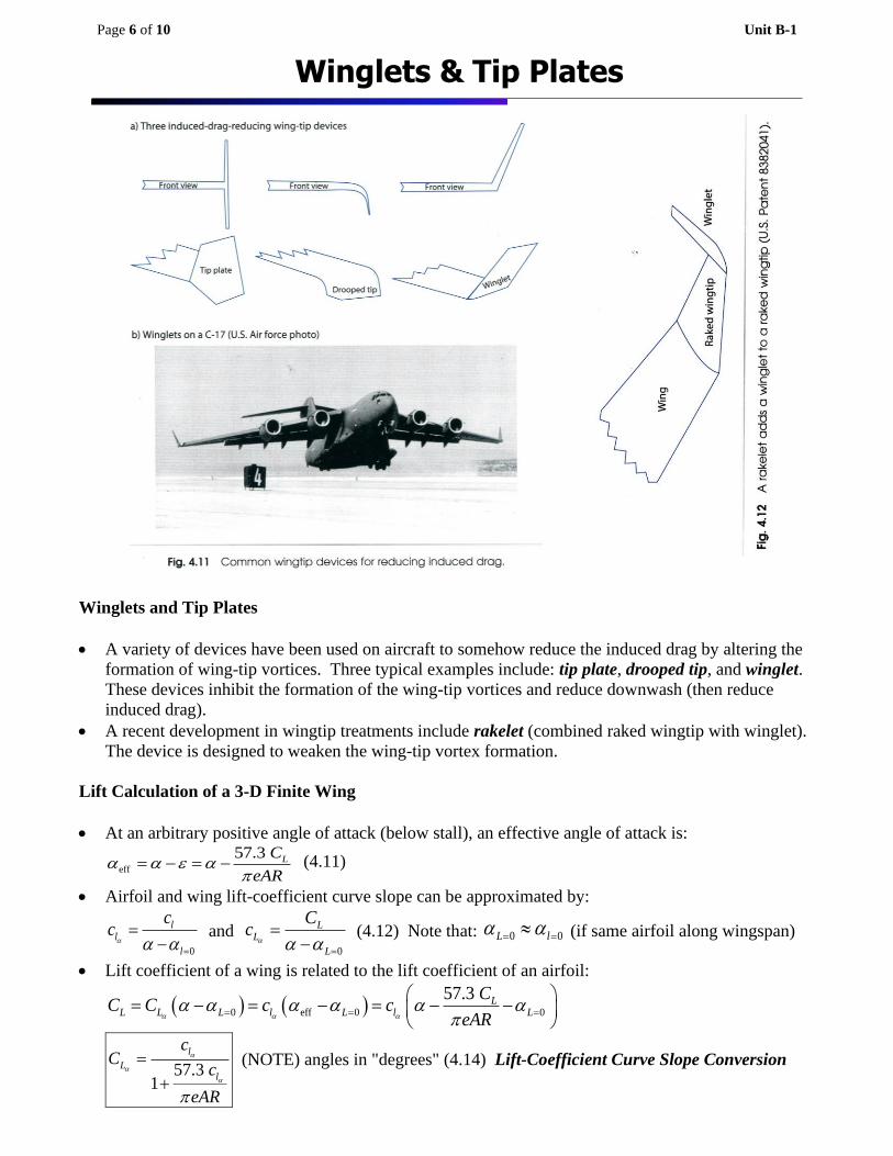
Winglets and Tip Plates
• A variety of devices have been used on aircraft to somehow reduce the induced drag by altering the
formation of wing-tip vortices. Three typical examples include: tip plate, drooped tip, and winglet.
These devices inhibit the formation of the wing-tip vortices and reduce downwash (then reduce
induced drag).
• A recent development in wingtip treatments include rakelet (combined raked wingtip with winglet).
The device is designed to weaken the wing-tip vortex formation.
Lift Calculation of a 3-D Finite Wing
• At an arbitrary positive angle of attack (below stall), an effective angle of attack is:
eff
57.3 LC
eAR
= − = − (4.11)
• Airfoil and wing lift-coefficient curve slope can be approximated by:
0
ll
l
cc
=
=−
and 0
LL
L
Cc
=
=−
(4.12) Note that: 0 0L l = = (if same airfoil along wingspan)
• Lift coefficient of a wing is related to the lift coefficient of an airfoil:
( ) ( )0 eff 0 0
57.3 LL L L l L l L
CC C c c
eAR
= = =
= − = − = − −
57.3 1
l
Ll
cC
c
eAR
=
+
(NOTE) angles in "degrees" (4.14) Lift-Coefficient Curve Slope Conversion
Winglets & Tip Plates

Page 7 of 10 Unit B-1
_________________________________________________________
_________________________________________________________
_________________________________________________________
_________________________________________________________
_________________________________________________________
_________________________________________________________
_________________________________________________________
_________________________________________________________
_________________________________________________________
_________________________________________________________
_________________________________________________________
_________________________________________________________
_________________________________________________________
_________________________________________________________
_________________________________________________________
_________________________________________________________
_________________________________________________________
_________________________________________________________
_________________________________________________________
_________________________________________________________
_________________________________________________________
_________________________________________________________
_________________________________________________________
_________________________________________________________
_________________________________________________________
_________________________________________________________
_________________________________________________________
_________________________________________________________
_________________________________________________________
_________________________________________________________
_________________________________________________________
Solution (4.1)
Example B-1-1(Wing Lift & Drag)
A wing with a rectangular planform, a NACA 2412 airfoil, a span of 5 m, and a chord of 2 m is operating in standard sea-level atmospheric condition at a freestream velocity (magnitude) of 42 m/s and an angle of attack of 8 degrees. If the wing’s span efficiency factor is 0.9, how much lift and drag is it generating?
Example 4.1
Page 8 of 10 Unit B-1
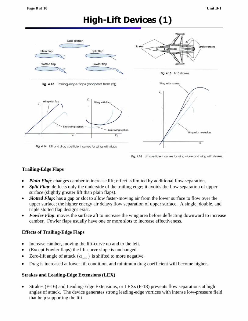
Trailing-Edge Flaps
• Plain Flap: changes camber to increase lift; effect is limited by additional flow separation.
• Split Flap: deflects only the underside of the trailing edge; it avoids the flow separation of upper
surface (slightly greater lift than plain flaps).
• Slotted Flap: has a gap or slot to allow faster-moving air from the lower surface to flow over the
upper surface; the higher energy air delays flow separation of upper surface. A single, double, and
triple slotted flap designs exist.
• Fowler Flap: moves the surface aft to increase the wing area before deflecting downward to increase
camber. Fowler flaps usually have one or more slots to increase effectiveness.
Effects of Trailing-Edge Flaps
• Increase camber, moving the lift-curve up and to the left.
• (Except Fowler flaps) the lift-curve slope is unchanged.
• Zero-lift angle of attack ( )0L = is shifted to more negative.
• Drag is increased at lower lift condition, and minimum drag coefficient will become higher.
Strakes and Leading-Edge Extensions (LEX)
• Strakes (F-16) and Leading-Edge Extensions, or LEXs (F-18) prevents flow separations at high
angles of attack. The device generates strong leading-edge vortices with intense low-pressure field
that help supporting the lift.
High-Lift Devices (1)
Page 9 of 10 Unit B-1
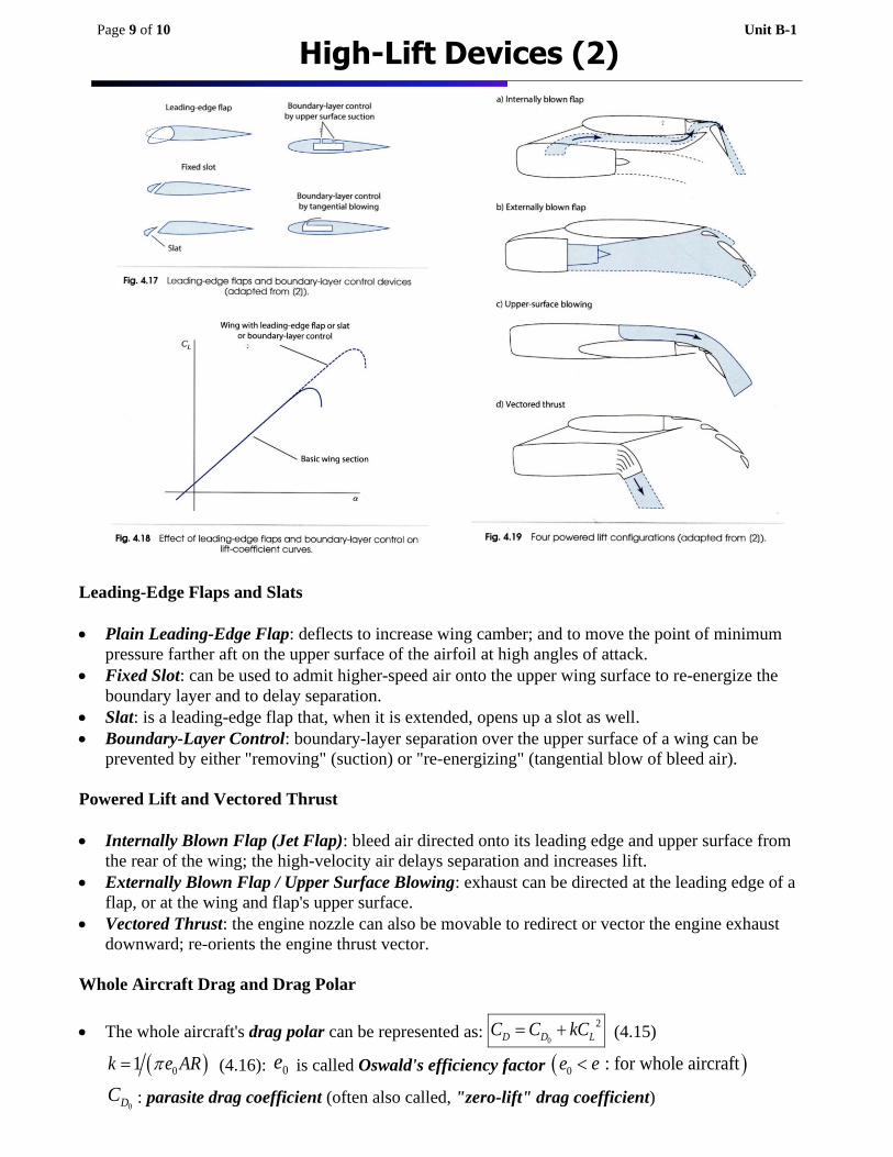
Leading-Edge Flaps and Slats
• Plain Leading-Edge Flap: deflects to increase wing camber; and to move the point of minimum
pressure farther aft on the upper surface of the airfoil at high angles of attack.
• Fixed Slot: can be used to admit higher-speed air onto the upper wing surface to re-energize the
boundary layer and to delay separation.
• Slat: is a leading-edge flap that, when it is extended, opens up a slot as well.
• Boundary-Layer Control: boundary-layer separation over the upper surface of a wing can be
prevented by either "removing" (suction) or "re-energizing" (tangential blow of bleed air).
Powered Lift and Vectored Thrust
• Internally Blown Flap (Jet Flap): bleed air directed onto its leading edge and upper surface from
the rear of the wing; the high-velocity air delays separation and increases lift.
• Externally Blown Flap / Upper Surface Blowing: exhaust can be directed at the leading edge of a
flap, or at the wing and flap's upper surface.
• Vectored Thrust: the engine nozzle can also be movable to redirect or vector the engine exhaust
downward; re-orients the engine thrust vector.
Whole Aircraft Drag and Drag Polar
• The whole aircraft's drag polar can be represented as: 0
2
D D LC C kC= + (4.15)
( )01k e AR= (4.16): 0e is called Oswald's efficiency factor ( )0 : for whole aircrafte e
0DC : parasite drag coefficient (often also called, "zero-lift" drag coefficient)
High-Lift Devices (2)

Page 10 of 10 Unit B-1
_________________________________________________________
_________________________________________________________
_________________________________________________________
_________________________________________________________
_________________________________________________________
_________________________________________________________
_________________________________________________________
_________________________________________________________
_________________________________________________________
_________________________________________________________
_________________________________________________________
_________________________________________________________
_________________________________________________________
_________________________________________________________
_________________________________________________________
_________________________________________________________
_________________________________________________________
_________________________________________________________
_________________________________________________________
_________________________________________________________
_________________________________________________________
_________________________________________________________
_________________________________________________________
_________________________________________________________
_________________________________________________________
_________________________________________________________
_________________________________________________________
_________________________________________________________
_________________________________________________________
Solution (4.2)
Example B-1-2(Whole Aircraft Lift & Drag)
The Avro Vulcan jet bomber aircraft is nearly an all-wing aircraft, with only a small fuselage section sticking forward of its large triangular-shaped (or delta) wing. Its wing uses a thin NACA 0009 airfoil and has a wingspan of 111 ft and planform area of 3,964 ft2. Assume that it’s flying in standard 5,000 ft atmospheric condition at a true airspeed of 300 ft/s and an angle of attack of 8 degrees. Its is 0.009, its span
efficiency factor is 0.9, its Oswald’s efficiency factor is 0.7, and its average wing chord length is 36 ft. Estimate how much lift and drag it is making for these conditions.
Example 4.2


![Mach number P w,test [bar] P model [bar] 1.8 -0.45 -0.20 0 ...ae342/18/lab2/lab2data.pdf · Mach 2.0 Snapshot . Mach 1.8 Snapshot . Mach 2.3 Snapshot Mach 2.2 Snapshot . P w,test](https://static.fdocuments.us/doc/165x107/5fb4e5220b26be1bae0aea08/mach-number-p-wtest-bar-p-model-bar-18-045-020-0-ae34218lab2-.jpg)