
High Level Design Space Exploration of Shared Bus ... · PDF fileHigh Level Design Space...
15
High Level Design Space Exploration of Shared Bus Communication Architectures * Sudeep Pasricha† Mohamed Ben-Romdhane‡ Nikil Dutt† [email protected] [email protected] [email protected] †Center for Embedded Computer Systems ‡Conexant Systems Inc. Department of Information and Computer Science 4000 Mac Arthur Blvd University of California Irvine, CA 92697 USA Newport Beach, CA 92660 USA CECS Technical Report #04-06 Center for Embedded Computer Systems University of California, Irvine CA 92697 Mar 13, 2004 Abstract System-on-Chip (SoC) designs are increasingly becoming more complex. Efficient on-chip communication architectures are critical for achieving desired performance in these systems. System designers typically use Bus Cycle Accurate (BCA) models written in high level languages such as C/C++ to explore the communication design space. These models capture all of the bus signals and strictly maintain cycle accuracy, which is useful for reliable performance exploration but results in slow simulation speeds for complex designs, even when they are modeled using high level languages. Recently there have been several efforts to use the Transaction Level Modeling (TLM) paradigm for improving simulation performance in BCA models. However these BCA models capture a lot of details that can be eliminated when exploring communication architectures. In this technical report we extend the TLM approach and propose a new and faster transaction-based modeling abstraction level (CCATB) to explore the communication design space. Our abstraction level bridges the gap between the TLM and BCA levels, and yields an average performance speedup of 55% over BCA models. We demonstrate how fast and accurate exploration of tradeoffs is possible for high-performance shared bus architectures such as AMBA 2.0 and AMBA 3.0 (AXI) in industrial strength designs at the proposed abstraction level. * This research was partially supported by grants from Conexant Systems Inc. and UC MICRO (03-029).
Transcript of High Level Design Space Exploration of Shared Bus ... · PDF fileHigh Level Design Space...
High Level Design Space Exploration of Shared Bus Communication Architectures ∗∗∗∗
Sudeep Pasricha† Mohamed Ben-Romdhane‡ Nikil Dutt† [email protected] [email protected] [email protected]
†Center for Embedded Computer Systems ‡Conexant Systems Inc. Department of Information and Computer Science 4000 Mac Arthur Blvd University of California Irvine, CA 92697 USA Newport Beach, CA 92660 USA
CECS Technical Report #04-06 Center for Embedded Computer Systems University of California, Irvine CA 92697
Mar 13, 2004
Abstract
System-on-Chip (SoC) designs are increasingly becoming more complex. Efficient on-chip communication architectures are critical for achieving desired performance in these systems. System designers typically use Bus Cycle Accurate (BCA) models written in high level languages such as C/C++ to explore the communication design space. These models capture all of the bus signals and strictly maintain cycle accuracy, which is useful for reliable performance exploration but results in slow simulation speeds for complex designs, even when they are modeled using high level languages. Recently there have been several efforts to use the Transaction Level Modeling (TLM) paradigm for improving simulation performance in BCA models. However these BCA models capture a lot of details that can be eliminated when exploring communication architectures.
In this technical report we extend the TLM approach and propose a new and faster transaction-based modeling abstraction level (CCATB) to explore the communication design space. Our abstraction level bridges the gap between the TLM and BCA levels, and yields an average performance speedup of 55% over BCA models. We demonstrate how fast and accurate exploration of tradeoffs is possible for high-performance shared bus architectures such as AMBA 2.0 and AMBA 3.0 (AXI) in industrial strength designs at the proposed abstraction level.
∗ This research was partially supported by grants from Conexant Systems Inc. and UC MICRO (03-029).

1. Introduction System-on-chip (SoC) designers are dealing with ever increasing design complexity. SoC designs today have several IPs (CPUs, DSPs, memories, peripherals etc.) which share the processing load and frequently exchange data over system busses. Communication inevitably becomes a bottleneck and on-chip bus configurations and protocols significantly affect overall system performance. Shared bus architectures such as OCP [5], AMBA [8] and CoreConnect [9] are popular choices for on-chip communication in current designs and open up a large exploration space because they can be configured in so many different ways. System designers need to explore tradeoffs between different communication protocols and configurations quickly, reliably and early in the design flow to make the right choices and eliminate performance bottlenecks under time-to-market pressures. Traditionally, systems were captured at a cycle and pin-accurate level in RTL and then simulated for performance estimation before synthesis. However SoC designs today are large and very complex, so not only does it take a lot of time to capture them in RTL, but the resulting simulation speed is too slow for meaningful performance exploration. To overcome these limitations, system designers have raised the abstraction level of system models. High level models (usually written in C/C++) give an early estimate of the system characteristics before committing to RTL development. To explore on-chip communication performance, bus cycle-accurate (BCA) models [14] are frequently used. These models capture IPs at a less detailed, functional level for improved simulation performance while modeling all the bus signals and timing accurately. Transaction Level Modeling (TLM) [1][2][10] has been proposed as a higher modeling abstraction level, above the BCA abstraction level, for faster simulation performance. At the TLM level, architecture IPs are modeled at a functional level and the system bus is captured as an abstract ‘channel', independent of a particular bus architecture or protocol implementation. A TLM model can be used as a golden prototype of the system and for early functional system validation and embedded software development [2]. However, these models do not capture enough detail about the on-chip bus to allow reliable exploration of the system. Recently there have been some efforts [11][12][13] to use concepts from the TLM level, which speed up simulation performance, and apply them at the BCA level. But these approaches do not fully exploit the potential for speedup when modeling systems for exploring on-chip communication tradeoffs and performance.
Figure 1. High-level System Modeling Flow
With the widespread acceptance of platform-based modeling [20], system designers are using a high-level modeling flow similar to the one shown in Figure 1. In this flow, a system specification is mapped onto a TLM platform model with a generic bus, and this model is then transformed into a BCA model. Although a BCA model allows reliable exploration of the communication space, our studies show that it takes more than twice the simulation time taken by TLM models, which is a drawback. In this paper we introduce a new modeling abstraction level called Cycle Count Accurate at Transaction Boundaries (CCATB) for on-chip communication archotecture exploration. Our abstraction level bridges the gap between the TLM and BCA levels, preserving the accuracy of BCA models while improving on their simulation speed. We propose a system design methodology that integrates our abstraction level in a system flow and in which CCATB models are derived from TLM models after refinement. We demonstrate the effectiveness of our approach by capturing an industrial SoC design at the proposed abstraction level and conducting several experiments that quickly and reliably explore the communication space. This report is organized as follows. Section 2 looks at some related work. Section 3 gives an overview of the AMBA bus architecture. Section 4 introduces our modeling abstraction for exploring on-chip communication architectures. Section 5 describes our system modeling methodology. Section 6 presents results from experiments performed on our models. Finally Section 7 concludes the report and gives directions for future work.
2. Related Work Transaction Level Models [1][2][10] are bit-accurate models of a system with specifics of the bus protocol replaced by a generic bus (or channel), and where communication takes place when IPs call read() and write() methods provided by the channel interface. Since detailed timing and pin-accuracy is omitted, these models are fast to simulate and are useful for early functional validation of the system. Gajski et al. [1] also proposed a top-down system design methodology with four models at different abstraction levels. The architecture model in their methodology corresponds to the TLM level of abstraction while the next lower abstraction level (called the communication model) is a BCA model where the generic channel has been replaced by bit and timing accurate signals corresponding to a specific bus protocol. Early work with TLM established SystemC 2.0 [3] as the modeling language of choice for the approach. [2] describes how TLM can be used for early system prototyping and embedded software development. Paulin et al. [4] define a system level exploration platform for network processors which need to handle high speed packet processing. The SOCP channel described in their approach is based on OCP [5] semantics and is essentially a simple TLM channel with a few added details such as support for split transactions [8]. Nicolescu et al. [15] propose a component based bottom-up system design methodology where IPs modeled at different abstractions are connected together with a generic channel like the one used in TLM, after encapsulating them with suitable wrappers. Commercial tools such as the Incisive Verification Platform [6], ConvergenSC System Designer [7] and Cocentric System Studio [16] have also started adding support for system modeling at the higher TLM abstraction, in addition to lower level RTL modeling. Recently, research efforts [11][12][13][14] have focused on adapting TLM concepts to speed up architecture exploration. Xinping et al. [11] use function calls instead of slower signal semantics to describe models of AMBA2 and CoreConnect bus architectures at a high abstraction level. However, the resulting models are not detailed enough for accurate communication exploration. Caldari et al. [12] similarly attempt to model AMBA2 using function calls for reads/writes on the bus, but also use SystemC events to emulate certain bus signals which can slow down simulation. Ogawa et al. [13] also model data transfers in AMBA2 using read/write transactions but use low level handshaking semantics in the models which need not be explicitly modeled to preserve cycle accuracy. Recently, ARM released the AHB Cycle-Level Interface Specification [14] which provides the definition and compliance requirements for modeling AHB at a cycle-accurate level in SystemC. Function calls are used to emulate all bus signals at the interface between IPs and the bus. Although using function calls speeds up simulation, there is a lot of opportunity for improvement by reducing the number of calls while maintaining cycle accuracy, as we show later in this report.
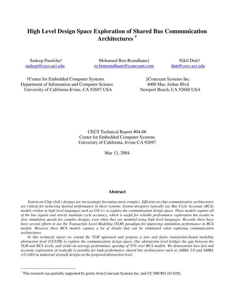
Figure 2. A typical AMBA based platform
3. AMBA Overview To illustrate our approach, we model a widely used on-chip bus standard – AMBA. This section briefly describes this standard.

AMBA is an on-chip bus specification that is widely used to interconnect IPs in System-on-chip (SoC) designs. A typical AMBA based design consists of a high-performance bus and a slower peripheral bus as shown in Figure 2. The three bus specifications in the AMBA 2.0 communication architecture are:
o AHB (Advanced High-performance Bus) o APB (Advanced Peripheral Bus) o ASB (Advanced System Bus)
The AHB bus is used for high bandwidth and low latency communication, primarily between CPU cores, high performance peripherals, DMA controllers, on-chip memories and interfaces such as bridges to the slower APB bus. The APB is used to connect slower peripherals such as timers, interrupt controllers etc. and uses a bridge to interface with the AHB. It is a simple bus that does not support the advanced features of the AHB bus. The ASB bus is an earlier version of the high-performance bus which has been superceded by AHB in current designs. Recently, ARM announced the release of AMBA 3.0 [18] with the next generation of high-performance bus protocol called the Advanced eXtensible Interface (AXI). In the following subsections we give a brief overview of the main features of the high performance bus protocols in AMBA. 3.1 AMBA 2.0 AHB The Advanced High-Performance Bus (AHB) is a high-speed, high-bandwidth bus that supports multiple masters. AHB supports a multi-layer bus architecture to optimize system bandwidth and improve performance. It supports pipelined operations for high speed memory and peripheral access without wasting precious bus cycles. Burst transfers allow optimal usage of memory interfaces by giving advance information of the nature of the transfers. AHB also allows split transactions which maximize the use of the system bus bandwidth by enabling high latency slaves to release the system bus during the dead time while the slave is completing its transaction. In addition, wide bus configurations from 32 up to 1024 bits wide are supported. 3.2 AMBA 3.0 AXI The Advanced eXtensible Interface (AXI) has all the advanced features of the AHB bus such as pipelined and burst transfers, multi-master configuration and a wide data bus. In addition, it has support for multiple outstanding transactions and out of order transaction completion, separate read and write channels, unaligned data transfer using byte strobes and improved burst mode operation (only the start address of the burst is broadcast on the address bus). AXI also provides enhanced protection support (secure/non-secure transactions), enhanced system cache/buffer support (pins for specifying write-back/write through attributes and allocation strategies), a FIXED burst mode (for repeated access to the same location) and exclusive access support for semaphore type operations. 4. CCATB Model Overview As the previous section indicated, bus architectures such as AMBA have several parameters which can be configured to improve performance. Bus topology, arbitration strategies, width and buffer sizes have significant impact on system performance. Our goal is to improve simulation performance for reliable exploration of on-chip communication architectures as early as possible in the design flow. The following subsections describe the requirements of this model and then elaborate on the model granularity and abstraction. 4.1 Requirements While developing our exploration framework we had several objectives. To obtain performance figures which were meaningful, we would have to capture the entire system and not just a portion of it. System IPs such as CPUs, memories and peripherals would have to be appropriately parameterized [21] and modeled at a granularity which would capture their precise functionality, yet not weigh down simulation speed due to unnecessary detail. They would also need to be annotated with timing wherever needed, for accuracy. Existing IPs that have been written at different abstraction levels (e.g. pin-accurate interface processor ISS models) should be easily adapted to fit into the framework by writing an appropriate wrapper to interface with our bus model. Performance numbers would be obtained by simulating the working of the entire system –

including running embedded software on the CPU architecture model. An important long-term requirement would be the ease of reuse of these IPs, to amortize design effort over a range of architecture derivatives. Our bus model would be required to support all the advanced high-performance bus features such as pipelined operation, hierarchy, SPLIT/RETRY transactions, Out-of-Order transaction completion, burst modes, exclusive (semaphore) access and protection modes etc. The bus interface to SoC IPs was motivated by the following requirements. It should: � be independent of the underlying architecture to allow effortless plug-and-play of different on-chip communication
architectures (e.g. AMBA, OCP, CoreConnect etc.) � be generic enough to ease refinement from higher level (timing-independent) TLM models to lower level cycle/pin-
accurate models � avoid modeling protocol signals due to simulation overhead – instead function calls should be used Ultimately the model should be fast, accurate and flexible – providing good simulation speed, cycle accuracy for reliable performance estimation and the flexibility to seamlessly plug-and-run different bus architectures and IPs such as processors, memories and peripherals. 4.2 Modeling language We chose the SystemC 2.0 language [3][10] to develop our model. SystemC provides a rich set of primitives for communication and synchronization - channels, ports, interfaces, events, signals and wait-state insertion. Concurrent execution is performed by multiple threads and processes (lightweight threads) and execution schedule is governed by the scheduler. SystemC also supports capture of a wide range of modeling abstractions from high level specifications to pin and timing accurate system models. Since it is a library based on C++, it is object oriented, modular and allows data encapsulation – all of which are essential for easing IP distribution, reuse and adaptability across different modeling abstraction levels. 4.3 Model Abstraction The granularity of our proposed abstraction level is ‘cycle accurate’ when viewed at ‘transaction boundaries’. For that reason we call our model Cycle Count Accurate at Transaction Boundaries (CCATB). Our channel model ensures that cycle accuracy is preserved at the end of every transaction i.e. the number of bus cycles that elapse at the end of a transaction is the same when compared to cycles elapsed in a detailed cycle/signal accurate system model. A similar concept can be found in [19] where Observable Time Windows were defined and used for verifying results of high level synthesis. In essence, our model trades off intra-transaction visibility for simulation speedup. Improved simulation performance in our model is because: � cycle accuracy is preserved only at transaction boundaries – within a transaction we avoid multiple re-activations of IP
threads. Computation operations are clustered together and completed in near zero time, while simulation time is increased in chunks, which speeds up simulation while maintaining accurate cycle count at the end of the transaction
� IPs (including bridges to slower peripheral busses) that do not have useful work to perform in a cycle do not get activated � lightweight ‘processes’ are used instead of more resource hungry and time consuming threads wherever possible (e.g.
certain tasks inside masters, in slaves and in bus) � multiple single-word transactions are bunched together into bursts which reduces function call overhead � expensive signal synchronization overhead is eliminated since function calls are used instead of signals

Figure 3. Transaction execution sequence
On-chip bus architectures are modeled by extending the TLM channel [2] to include timing and protocol details specific to the bus architecture used. Arbiter and decoder modules are integrated with this channel model. On a positive clock edge, masters send transaction requests to the channel, which are recorded in an outstanding request queue. A transaction is a single-word read/write transfer or a burst (collection) of reads and writes issued by a master. On the next negative clock edge, the arbiter selects a request from this queue after applying an arbitration strategy, decodes the destination address and sends the request to the slave destination. Bus cycles for arbitration delay, contention and decoding are accounted for at this stage. The slave receives the request from the arbiter, performs any required computation, the read/write operation and optionally waits for a fixed number of cycles before sending a response back to the arbiter. In the case of a SPLIT or Our-of-Order transaction, the slave sends a response immediately and the arbiter ensures eventual completion of the transaction. The arbiter then accounts for the burst length, pipeline, busy and idle cycle delays and finally sends the response back to the master. Figure 3 illustrates the sequence of events that makes up a transaction in our model. In our model, we captured system IPs at the transaction abstraction level [2]. Masters are active blocks with computation threads and an interface with the bus architecture to communicate with slaves. One of our goals was to keep a consistent interface when refining models from the TLM level down to our CCATB level. The interface used at both these levels is shown below:

status = readData (&bus_port, addr, &data_cntrl);
and
status = writeData (&bus_port, addr, &data_cntrl);
At the CCATB level, masters (and slaves) are connected to a bus through ports, as defined in SystemC. bus_port specifies the port to send the read/write request on (since a master may be connected to multiple busses). addr is the address of the slave to send the transaction to. data_cntrl is a structure that contains pointers to data and control information. Table 1 shows the fields in this data structure passed by the master and received by the arbiter. status is the status of the transaction, as returned by the slave.
Table 1. Fields in data_cntrl structure At the TLM level, since the bus is modeled as an abstract channel without including any specific details of the bus protocol, the data_cntrl structure contains just the m_data, m_burst_length and m_byte_enable fields. The other fields are specific to bus protocols and are thus omitted since we are only concerned with transferring data packets from the source to its destination at this level. Thus, when we refine a master IP from the TLM level to the CCATB level, the only change is to set protocol specific parameters before calling the interface functions. Slaves are passive entities, activated only when triggered by the arbiter on a request from the master, and have a register/memory map to handle read/write requests. The arbiter calls read() and write() functions implemented in the slave. An excerpt of the read function from a memory controller is shown below: inline channel_status_slave * mem_contr::read(MEMCONTR_ADDR_TYPE addr_in, slave_data_and_control * packet) { … // check if initial NOPs have been generated … // check if latency cycles have expired before … switch (addr_in - m_start_address) { case MEMCONTR_MODE: *(packet->data) = memcontr_mode; slave_status->status = BUS_OK; return slave_status; break; case MEMCONTR_RESET: … }
Request field Description m_data pointer to an array of data m_burst_length length of transaction burst m_burst_type type of burst (incr, fixed, wrapping etc.) m_byte_enable byte enable strobe for unaligned transfers m_read indicates whether transaction is read/write m_lock lock bus during transaction m_cache cache/buffer hints m_prot protection modes m_transID transaction ID (needed for OO access etc.) m_busy_idle schedule of busy/idle cycles from master m_ID ID for identifying the master
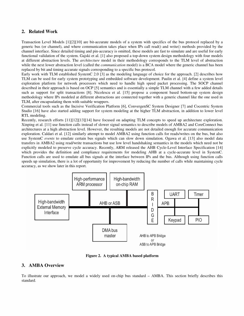
Slaves can also have optional (lightweight) processes triggered by SystemC events, to perform computation if needed. The functionality of the slave IP remains unchanged when refining the model from the TLM level to the CCATB level, unless the slave IP supports special bus protocol specific features such as having an outstanding instruction queue for out-of-order transaction completion in the AXI protocol, in which case these details need to be added. Figures 4 (a), (b) and (c) illustrate how the CCATB model maintains cycle accuracy at transaction boundaries for different call sequences of the AMBA 2.0 protocol. In Figure 4 (a) a master requests an incremental write burst of length 4 data packets and the arbiter grants it access to the bus. The transaction is initiated and data sent to the slave, but before it can process the final data packet in the sequence, the slave needs to perform involved computation with the previously written data, which takes up 2 cycles. For this duration, the slave drives the HREADY signal low to indicate to the master that it is not ready yet to receive the final data packet in the burst. The burst transaction resumes once the slave drives HREADY high. In the CCATB model, the arbiter accounts for the request (REQ), arbitration (ARB), burst length (BURST_LEN) and pipeline startup (PPL) delays and increments simulation time accordingly. The arbiter then invokes the slave which in turn increments simulation time depending on whether there is a computational delay. In this case, the slave accounts for the 2 cycle delay (RDY) at the end of the burst transaction. The slave returns the status of the writes at the end of the transaction to the arbiter, which in turn routes this information to the master. Figure 4 (b) illustrates the same scenario, but this time there is delay in generating the data at the master end instead of a processing delay at the slave end. After the write burst initiates, the master indicates that it requires extra cycles to generate write data for the slave by sending a BUSY status on the HRESP[1:0] lines. In the CCATB model, the arbiter gets a schedule of busy cycles from the master when it receives the transaction request, and thus it accounts for the BUSY cycle delay in the transaction, along with the other delays discussed above. There is no delay at the slave and consequently no increment in simulation time at the slave in this case. In Figure 4 (c), after a master requests access to the bus for a write burst, another master requests the bus for a write burst. While there is no delay at the master or the slave end for the first write burst, there is delay in generating the data at the master end for master M2, which is indicated by the BUSY status on the HRESP[1:0] lines. In the CCATB model, the arbiter accounts for the REQ, ARB, BURST_LEN and PPL delays and increments simulation time. For the subsequent transaction by master M2, the request has already been registered at the arbiter and no arbitration is required, so there is no REQ or ARB delay. Since transfers are pipelined, there is also no pipeline startup delay like in the case of master M1. Thus there is no PPL delay. There is however delay which is dependent on the burst length (BURST_LEN) and the busy cycles (BUSY) which is accounted for by the arbiter. Like in the previous scenario, the slave does not delay either of the burst transactions, so there is no simulation time increment at the slave end.
Figure 4 (a) Reference AMBA2 call sequence 1

Figure 4 (b) Reference AMBA2 call sequence 2
Figure 4 (c) Reference AMBA2 call sequence 3

4.4 Heterogeneous IP Abstraction in CCATB Sometimes it might be the case that early in the design flow, very little information is available about a particular IP. In such a case, the designer might have an idea about the rate at which the IP generates or consumes data. For instance the designer might know that a switch interface module receives 1.5 Gigabits of data every second from an external source and sends it to the system bus at the same rate. In such a case if we know the speed of the bus, it is easy to figure out how often the module sends transactions on the bus in the CCATB model, and thus still maintain reasonable amount of accuracy while exploring the system. Suppose we connect the switch IP to a 100 MHz bus with a data bus width of 64 bits. This implies that at most 64 bits can be transferred over the system bus in one cycle and the maximum theoretical bandwidth of the bus is 6.4 Gigabits/sec. Of course the actual bandwidth is going to be much less than the theoretical bandwidth because of request/acknowledge, arbitration and computation delays in the IPs attached to the bus. Then according to our coarse estimates, the switch should load the bus with a (single) write transaction every 4 cycles to maintain its throughput requirements. While this seems like a feasible scenario for the case when the switch is the only master on the bus and the slave can consume the data as it receives it without any delay, the requirement might not be met if either of these two conditions does not hold, i.e. if there are more masters contending for the bus or if the slave cannot handle the high rate of data arrival. The CCATB model can thus provide figures to indicate whether throughput requirements for an IP will be met or not, even if its functionality is not completely known at the time of modeling. The converse problem is the case where preexisting IPs are modeled in cycle accurate detail and have a detailed (e.g. signal accurate) interface which need to be incorporated in an exploration framework for performance analysis of a system. In such a case, in accordance with the principle of Interface Based Design [17], we allow master and slave IPs modeled at different abstraction levels or with different interfaces to be incorporated in the CCATB model using an adapter written in SystemC. For instance, adapter code written in SystemC was used by us to interface signal accurate ARM processor ISS models with the transaction based TLM/CCATB SystemC interface. This allowed us to run application code on the ISS, which improved exploration accuracy and reliability.
Figure 5. System Design Flow
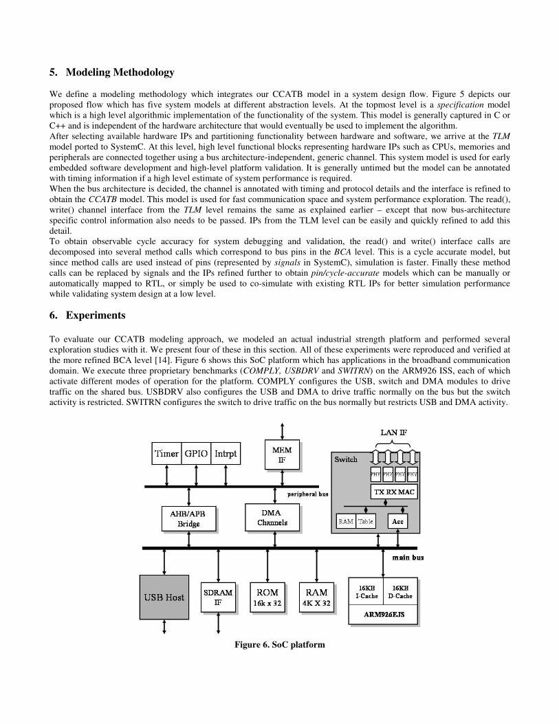
5. Modeling Methodology We define a modeling methodology which integrates our CCATB model in a system design flow. Figure 5 depicts our proposed flow which has five system models at different abstraction levels. At the topmost level is a specification model which is a high level algorithmic implementation of the functionality of the system. This model is generally captured in C or C++ and is independent of the hardware architecture that would eventually be used to implement the algorithm. After selecting available hardware IPs and partitioning functionality between hardware and software, we arrive at the TLM model ported to SystemC. At this level, high level functional blocks representing hardware IPs such as CPUs, memories and peripherals are connected together using a bus architecture-independent, generic channel. This system model is used for early embedded software development and high-level platform validation. It is generally untimed but the model can be annotated with timing information if a high level estimate of system performance is required. When the bus architecture is decided, the channel is annotated with timing and protocol details and the interface is refined to obtain the CCATB model. This model is used for fast communication space and system performance exploration. The read(), write() channel interface from the TLM level remains the same as explained earlier – except that now bus-architecture specific control information also needs to be passed. IPs from the TLM level can be easily and quickly refined to add this detail. To obtain observable cycle accuracy for system debugging and validation, the read() and write() interface calls are decomposed into several method calls which correspond to bus pins in the BCA level. This is a cycle accurate model, but since method calls are used instead of pins (represented by signals in SystemC), simulation is faster. Finally these method calls can be replaced by signals and the IPs refined further to obtain pin/cycle-accurate models which can be manually or automatically mapped to RTL, or simply be used to co-simulate with existing RTL IPs for better simulation performance while validating system design at a low level. 6. Experiments To evaluate our CCATB modeling approach, we modeled an actual industrial strength platform and performed several exploration studies with it. We present four of these in this section. All of these experiments were reproduced and verified at the more refined BCA level [14]. Figure 6 shows this SoC platform which has applications in the broadband communication domain. We execute three proprietary benchmarks (COMPLY, USBDRV and SWITRN) on the ARM926 ISS, each of which activate different modes of operation for the platform. COMPLY configures the USB, switch and DMA modules to drive traffic on the shared bus. USBDRV also configures the USB and DMA to drive traffic normally on the bus but the switch activity is restricted. SWITRN configures the switch to drive traffic on the bus normally but restricts USB and DMA activity.
Figure 6. SoC platform
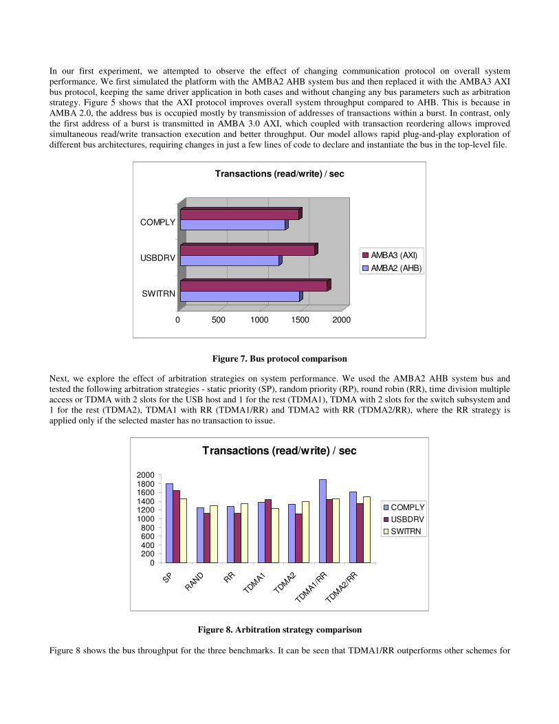
In our first experiment, we attempted to observe the effect of changing communication protocol on overall system performance. We first simulated the platform with the AMBA2 AHB system bus and then replaced it with the AMBA3 AXI bus protocol, keeping the same driver application in both cases and without changing any bus parameters such as arbitration strategy. Figure 5 shows that the AXI protocol improves overall system throughput compared to AHB. This is because in AMBA 2.0, the address bus is occupied mostly by transmission of addresses of transactions within a burst. In contrast, only the first address of a burst is transmitted in AMBA 3.0 AXI, which coupled with transaction reordering allows improved simultaneous read/write transaction execution and better throughput. Our model allows rapid plug-and-play exploration of different bus architectures, requiring changes in just a few lines of code to declare and instantiate the bus in the top-level file.
0 500 1000 1500 2000
SWITRN
USBDRV
COMPLY
Transactions (read/write) / sec
AMBA3 (AXI)AMBA2 (AHB)
Figure 7. Bus protocol comparison Next, we explore the effect of arbitration strategies on system performance. We used the AMBA2 AHB system bus and tested the following arbitration strategies - static priority (SP), random priority (RP), round robin (RR), time division multiple access or TDMA with 2 slots for the USB host and 1 for the rest (TDMA1), TDMA with 2 slots for the switch subsystem and 1 for the rest (TDMA2), TDMA1 with RR (TDMA1/RR) and TDMA2 with RR (TDMA2/RR), where the RR strategy is applied only if the selected master has no transaction to issue.
Transactions (read/write) / sec
0200400600800
100012001400160018002000
SPRAND RR
TDMA1
TDMA2
TDMA1/
RR
TDMA2/
RR
COMPLYUSBDRVSWITRN
Figure 8. Arbitration strategy comparison Figure 8 shows the bus throughput for the three benchmarks. It can be seen that TDMA1/RR outperforms other schemes for
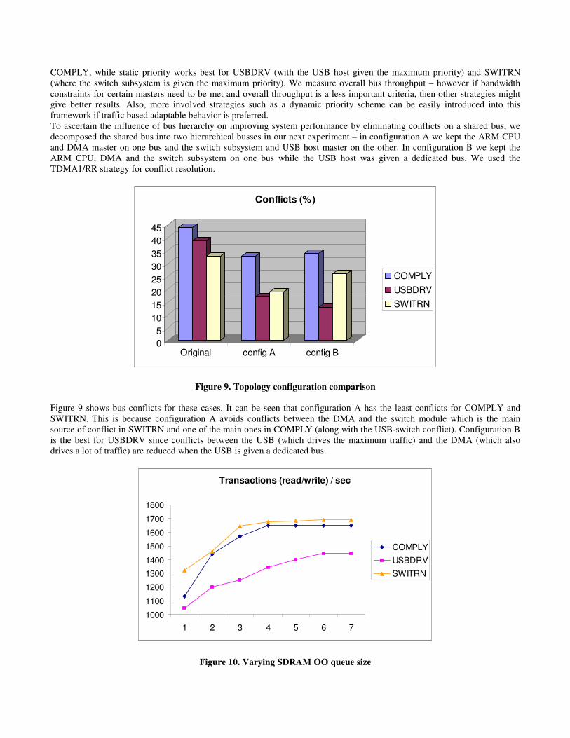
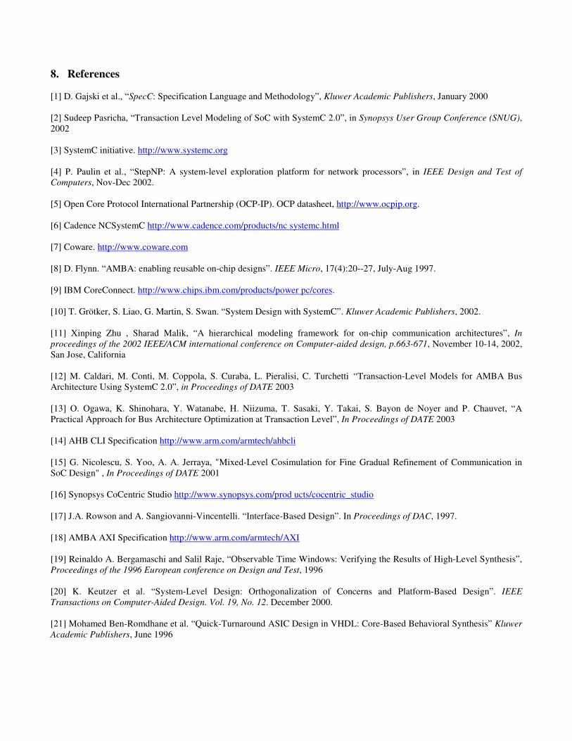
COMPLY, while static priority works best for USBDRV (with the USB host given the maximum priority) and SWITRN (where the switch subsystem is given the maximum priority). We measure overall bus throughput – however if bandwidth constraints for certain masters need to be met and overall throughput is a less important criteria, then other strategies might give better results. Also, more involved strategies such as a dynamic priority scheme can be easily introduced into this framework if traffic based adaptable behavior is preferred. To ascertain the influence of bus hierarchy on improving system performance by eliminating conflicts on a shared bus, we decomposed the shared bus into two hierarchical busses in our next experiment – in configuration A we kept the ARM CPU and DMA master on one bus and the switch subsystem and USB host master on the other. In configuration B we kept the ARM CPU, DMA and the switch subsystem on one bus while the USB host was given a dedicated bus. We used the TDMA1/RR strategy for conflict resolution.
05
1015202530354045
Original config A config B
Conflicts (%)
COMPLYUSBDRVSWITRN
Figure 9. Topology configuration comparison Figure 9 shows bus conflicts for these cases. It can be seen that configuration A has the least conflicts for COMPLY and SWITRN. This is because configuration A avoids conflicts between the DMA and the switch module which is the main source of conflict in SWITRN and one of the main ones in COMPLY (along with the USB-switch conflict). Configuration B is the best for USBDRV since conflicts between the USB (which drives the maximum traffic) and the DMA (which also drives a lot of traffic) are reduced when the USB is given a dedicated bus.
Transactions (read/write) / sec
1000
1100
1200
13001400
1500
1600
1700
1800
1 2 3 4 5 6 7
COMPLYUSBDRVSWITRN
Figure 10. Varying SDRAM OO queue size

Finally, we study the effect of changing outstanding request queue size for the SDRAM IF module which supports out-of-order execution of read/write requests as specified by the AMBA3 AXI protocol [18]. Figure 10 shows the effect of change in performance when the queue size is changed. It can be seen that performance saturates and no more gain can be obtained after the queue size has been increased to 4 for COMPLY, and 6 for SWITRN and USBDRV. This is a limit on the number of simultaneous requests issued at any given time for the SDRAM IF by the masters in the system for these benchmarks. It can be seen that this parameter is highly application dependent and changes with changing application requirements, demonstrating the need for this type of an exploration environment. To validate our approach we compared the results of all our exploration experiments on the CCATB model with results obtained on the bus cycle-accurate (BCA) model described in [14]. The performance statistics obtained at the end of simulation for these explorations were verified to be the same for both models. Figure 11 compares the simulation speeds in terms of number of transactions executed every second for our CCATB model and the BCA model for the topology configuration comparison experiment (Figure 9). In the figure, orig_c refers to the COMPLAY benchmark executing on the original configuration, A_u refers to the USBDRV benchmark executing on configuration A, and so on. It is apparent from the results that the CCATB model consistently performs better than the BCA model by almost 55% on an average. This speedup is invaluable when exploring the communication space of complex SoC designs running large time-consuming applications.
0
200
400
600
800
1000
1200
1400
1600
1800
orig_c orig_u orig_s A_c A_u A_s B_c B_u B_s
Transactions (read/write) / sec
CCATBBCA
Figure 11. Simulation performance comparison 7. Conclusion and Future Work We presented the Cycle Count Accurate at Transaction Boundaries (CCATB) modeling abstraction which is a fast, efficient and flexible approach for exploring the vast communication space for shared-bus architectures in SoC designs. Models at this abstraction level possess the accuracy of BCA models, yet they simulate almost 55% faster on average. This improved simulation performance comes at the cost of intra-transaction visibility during execution. Our models allow plug-and-play exploration of various facets of the communication space such as entire communication architectures and their arbitration strategies. IPs can be easily removed and replaced with their architecture variants, as long as their interface is the same. Existing IPs, which have different interfaces, can be adapted to our approach by using appropriate wrappers. We also propose a five layer design methodology that incorporates our CCATB abstraction level. Interface refinement from higher abstraction levels to lower levels is simplified as we avoid altering the interface between IPs and the communication channel as much as possible. This also eases co-simulation of SoC IPs modeled at different abstraction levels in our system flow. We have successfully applied our approach to the industrial strength broadband communication domain SoC design, and performed several exploration studies, some of which are presented in this paper. Our future work will focus on modeling the OCP [5] and CoreConnect [9] bus architectures at the CCATB abstraction. We are also working on automating the refinement of the communication interface from the TLM level down to the pin/cycle accurate level. This will be the basis for interconnect and IP based architecture synthesis.
8. References [1] D. Gajski et al., “SpecC: Specification Language and Methodology”, Kluwer Academic Publishers, January 2000 [2] Sudeep Pasricha, “Transaction Level Modeling of SoC with SystemC 2.0”, in Synopsys User Group Conference (SNUG), 2002 [3] SystemC initiative. http://www.systemc.org [4] P. Paulin et al., “StepNP: A system-level exploration platform for network processors”, in IEEE Design and Test of Computers, Nov-Dec 2002. [5] Open Core Protocol International Partnership (OCP-IP). OCP datasheet, http://www.ocpip.org. [6] Cadence NCSystemC http://www.cadence.com/products/nc systemc.html [7] Coware. http://www.coware.com [8] D. Flynn. “AMBA: enabling reusable on-chip designs”. IEEE Micro, 17(4):20--27, July-Aug 1997. [9] IBM CoreConnect. http://www.chips.ibm.com/products/power pc/cores. [10] T. Grötker, S. Liao, G. Martin, S. Swan. “System Design with SystemC”. Kluwer Academic Publishers, 2002. [11] Xinping Zhu , Sharad Malik, “A hierarchical modeling framework for on-chip communication architectures”, In proceedings of the 2002 IEEE/ACM international conference on Computer-aided design, p.663-671, November 10-14, 2002, San Jose, California [12] M. Caldari, M. Conti, M. Coppola, S. Curaba, L. Pieralisi, C. Turchetti “Transaction-Level Models for AMBA Bus Architecture Using SystemC 2.0”, in Proceedings of DATE 2003 [13] O. Ogawa, K. Shinohara, Y. Watanabe, H. Niizuma, T. Sasaki, Y. Takai, S. Bayon de Noyer and P. Chauvet, “A Practical Approach for Bus Architecture Optimization at Transaction Level”, In Proceedings of DATE 2003 [14] AHB CLI Specification http://www.arm.com/armtech/ahbcli [15] G. Nicolescu, S. Yoo, A. A. Jerraya, "Mixed-Level Cosimulation for Fine Gradual Refinement of Communication in SoC Design" , In Proceedings of DATE 2001 [16] Synopsys CoCentric Studio http://www.synopsys.com/prod ucts/cocentric_studio [17] J.A. Rowson and A. Sangiovanni-Vincentelli. “Interface-Based Design”. In Proceedings of DAC, 1997. [18] AMBA AXI Specification http://www.arm.com/armtech/AXI [19] Reinaldo A. Bergamaschi and Salil Raje, “Observable Time Windows: Verifying the Results of High-Level Synthesis”, Proceedings of the 1996 European conference on Design and Test, 1996 [20] K. Keutzer et al. “System-Level Design: Orthogonalization of Concerns and Platform-Based Design”. IEEE Transactions on Computer-Aided Design. Vol. 19, No. 12. December 2000. [21] Mohamed Ben-Romdhane et al. “Quick-Turnaround ASIC Design in VHDL: Core-Based Behavioral Synthesis” Kluwer Academic Publishers, June 1996


![Fast Exploration of Bus-Based Communication …sudeep/wp-content/...Shared-bus based communication architectures such as ARM AMBA [Flynn 1997], Sonics MicroNetwork [Wingard 2001],](https://static.fdocuments.us/doc/165x107/5f427b5493afac53101be27d/fast-exploration-of-bus-based-communication-sudeepwp-content-shared-bus-based.jpg)


