
High Induction Slot Apr 09 - S-air · PDF 5 High Induction Slot Diffusers End Flanges and End...
16
April 2009 High Induction Slot Diffusers Features ● 2 Slot Widths ● 2 Flange Styles ● 1 to 4 Slots ● Aluminium Frame Construction ● Cylinder Inner Deflectors ● Swivel Discharge Adjustment ● Matching Plenum Boxes Models LD13, LD130, LD14 and LD140 High Induction Slot Diffusers Grilles Diffusers Louvres Chilled Beams Ruskin Air Management Limited www.ruskinuk.co.uk
Transcript of High Induction Slot Apr 09 - S-air · PDF 5 High Induction Slot Diffusers End Flanges and End...
April 2009 High Induction Slot Diffusers
Features
● 2 Slot Widths
● 2 Flange Styles
● 1 to 4 Slots
●Aluminium FrameConstruction
●Cylinder InnerDeflectors
● Swivel DischargeAdjustment
●Matching PlenumBoxes
Models LD13, LD130, LD14 and LD140
High InductionSlot Diffusers
Grilles Diffusers Louvres Chilled Beams
Ruskin Air Management Limitedwww.ruskinuk.co.uk

2
Page
Contents Page 2
Introduction Page 3
Specification, Diffuser and Air Discharge Patterns Page 4
End Flanges, Corner and Angle Section Page 5
Performance Guide Pages 6 - 9
Installation Guide and Dimensions – Diffuser Page 10
Dimensions – Diffuser Page 11
Ordering Information – Diffuser Page 12
Specification – Plenum Boxes Page 13
Dimensions - Plenum Boxes Page 14
Installation and Ordering Information – Plenum Boxes Pages 15
Contents
www.air-diffusion.co.uk
High Induction Slot Diffusers
3
Introduction
www.air-diffusion.co.uk
Models LD13, LD130, LD14 & LD140Swivel Slot Diffusers
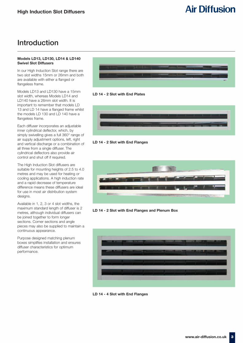
In our High Induction Slot range there aretwo slot widths 15mm or 26mm and bothare available with either a flanged orflangeless frame.
Models LD13 and LD130 have a 15mmslot width, whereas Models LD14 andLD140 have a 26mm slot width. It isimportant to remember that models LD13 and LD 14 have a flanged frame whilstthe models LD 130 and LD 140 have aflangeless frame.
Each diffuser incorporates an adjustableinner cylindrical deflector, which, bysimply swivelling gives a full 360° range ofair supply adjustment options, left, rightand vertical discharge or a combination ofall three from a single diffuser. Thecylindrical deflectors also provide aircontrol and shut off if required.
The High Induction Slot diffusers aresuitable for mounting heights of 2.5 to 4.0metres and may be used for heating orcooling applications. A high induction rateand a rapid decrease of temperaturedifference means these diffusers are idealfor use in most air distribution systemdesigns.
Available in 1, 2, 3 or 4 slot widths, themaximum standard length of diffuser is 2metres, although individual diffusers canbe joined together to form longersections. Corner sections and anglepieces may also be supplied to maintain acontinuous appearance.
Purpose designed matching plenumboxes simplifies installation and ensuresdiffuser characteristics for optimumperformance.
High Induction Slot Diffusers
LD 14 - 2 Slot with End Plates
LD 14 - 2 Slot with End Flanges
LD 14 - 2 Slot with End Flanges and Plenum Box
LD 14 - 4 Slot with End Flanges

a b
c
Standard (left, right)
Discharge angle
Min
. air
flow
rat
e
Discharge direction
Max
. air
flow
rat
e
d
fe g
Standard (left, right)
Standard (left)
Standard (vertical)
Air jet angle 60° (right)
Air jet angle 60° (right)
Air jet angle 60° (left, right)
4 www.air-diffusion.co.uk
MaterialsExtrudedAluminium withinner cylindersfrom recycledplastics.
Slot Sizes15mm - LD13 orLD13026mm - LD14 orLD140.
Flange SizesLD13 - 12.5mmFlange.
LD14 - 12.5mmFlange.
LD130 - 12.5mmFlangeless Border
LD140 - 5mmFlangeless Border
FinishStandard finish isAnodisedAluminium.
Optional FinishWhite PPCRAL9010 (20%Gloss), otherfinishes availableon request.
Inner CylindersStandard finish iseither Black orWhite (If colournot stated onorder then Blackcylinders will besupplied).
FixingsDiffuser toplenum standardis Type Z concealedcross memberfixing.
OptionalFixingsType ‘R’ HangerBrackets (seepage 6).
Specification - Diffuser
High Induction Slot Diffusers

5www.air-diffusion.co.uk
High Induction Slot Diffusers
End Flanges and End Plates
Corner and Angle Sections
End SealsEnd seals are components of the diffuser face plate. They areavailable in two designs:-
1. as a angle piece (E – on both ends, ET – on one end only)
or
2. plates (F– on both ends, FT– on one end only). F and FT end plates only on models LD130 and LD140.
E/ET
F/FT
3
300
300
Slot diffuser face plate designsSlot diffuser face plates are made of linear or angular endedsections, which allow the diffusers to be joined at different angles.Angular ended sections are not fitted with air direction controls.
Note: Other angle sections by special request.
1. End Flange 2. End Plate
Angle 90°
StandardDimensions
6 www.air-diffusion.co.uk
High Induction Slot Diffusers
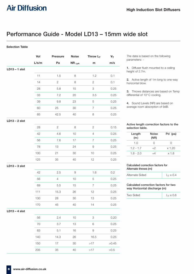
Vol Pressure Noise Throw LT VT
L/s/m Pa NR LpA m m/s
LD13 – 1 slot
11 1.5 8 1.2 0.1
14 2 8 2 0.1
28 5.8 15 3 0.25
33 7.2 20 3.5 0.25
39 9.8 23 5 0.25
60 25 30 7 0.25
85 42.5 40 8 0.25
LD13 – 2 slot
28 2 8 2 0.15
42 4.6 10 4 0.25
56 7.6 17 7 0.25
78 13 24 9 0.25
100 21 30 10 0.25
125 35 40 12 0.25
LD13 – 3 slot
42 2.5 9 1.6 0.2
56 4 10 5 0.25
69 5.5 15 7 0.25
111 15.3 26 12 0.25
130 28 30 13 0.25
170 45 40 14 0.25
LD13 – 4 slot
56 2.4 10 3 0.20
70 3.7 13 6 0.25
83 5.1 16 9 0.25
140 14.3 26 16.5 0.25
150 17 30 >17 >0.45
205 35 40 >17 >0.5
Selection Table
The data is based on the followingparameters: -
1. Diffuser flush mounted to a ceilingheight of 2.7m.
2. Active length of 1m long to one-wayhorizontal blow.
3. Throws distances are based on Tempdifferential of 10°C cooling.
4. Sound Levels (NR) are based onaverage room absorption of 9dB.
Performance Guide - Model LD13 – 15mm wide slot
Length Noise Pd (pa)(m) (NR)
1.0 0 0
1.2 - 1.7 +2 x 1.20
1.8 - 2.0 +4 x 1.8
Active length correction factors to theselection table.
Calculated correction factors for twoway Horizontal discharge (m)
Calculated correction factors for Alternate throws (m)
Alternate Sided LT x 0.4
Two Sided LT x 0.6
7www.air-diffusion.co.uk
High Induction Slot Diffusers
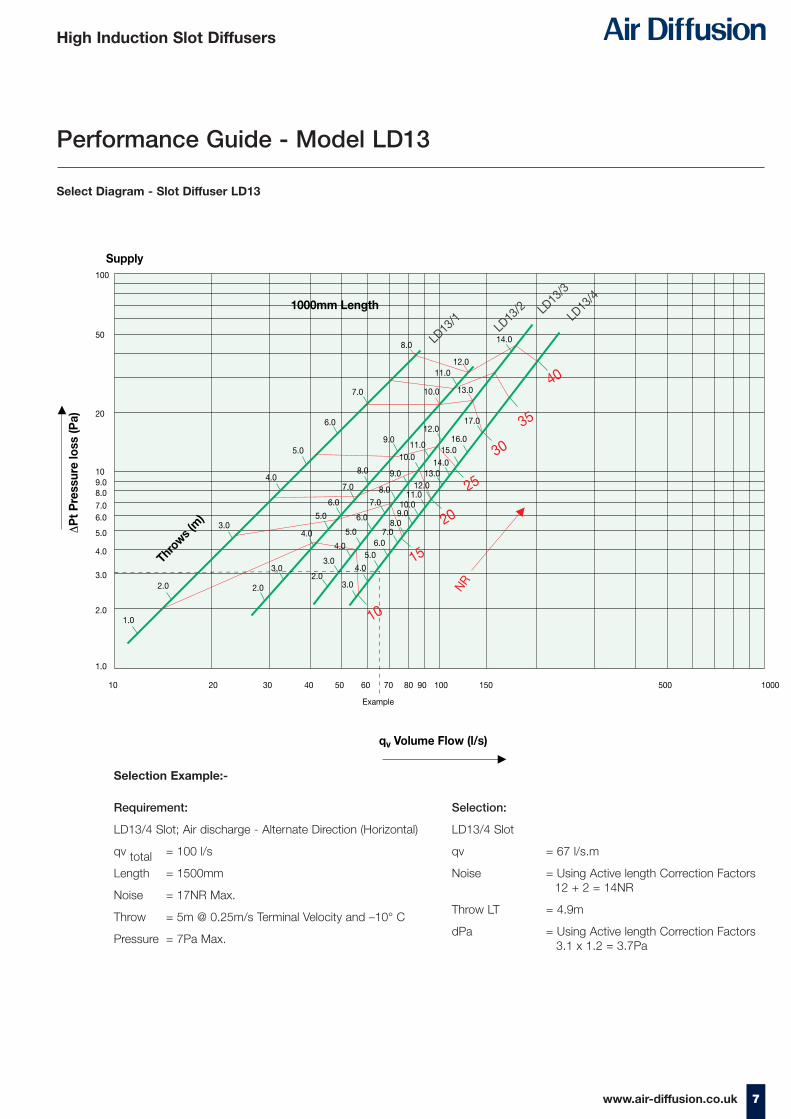
Select Diagram - Slot Diffuser LD13
Performance Guide - Model LD13
3.0
2.0
1.0
4.0
5.0
100
50
20
109.08.0
7.06.0
5.0
4.0
3.0
2.0
1.0
10 20 30 40 50 60 70
Example
80 90 100 150 500 1000
6.0
7.0
8.0
12.0
13.0
14.0
13.014.0
15.016.0
17.012.0
12.0
11.0
11.0
11.0
10.0
10.0
10.0
9.0
9.0
9.0
8.0
8.0
8.0
7.0
7.0
7.0
6.0
6.0
6.0
5.0
5.0
5.0
4.04.0
4.03.03.0
3.02.02.0
10
15
LD13
/1LD
13/2 LD
13/3
LD13
/4
20
25
30
35
40
1000mm Length
Supply
ΔP
t Pre
ssur
e lo
ss (P
a)
qv Volume Flow (l/s)
Throws (
m)
NR
Requirement:
LD13/4 Slot; Air discharge - Alternate Direction (Horizontal)
qv total = 100 l/s
Length = 1500mm
Noise = 17NR Max.
Throw = 5m @ 0.25m/s Terminal Velocity and –10° C
Pressure = 7Pa Max.
Selection:
LD13/4 Slot
qv = 67 l/s.m
Noise = Using Active length Correction Factors 12 + 2 = 14NR
Throw LT = 4.9m
dPa = Using Active length Correction Factors 3.1 x 1.2 = 3.7Pa
Selection Example:-

8 www.air-diffusion.co.uk
High Induction Slot Diffusers
Performance Guide - Model LD14 – 26mm wide slot
Selection Table
The data is based on the followingparameters: -
1. Diffuser flush mounted to a ceilingheight of 2.7m.
2. Active length of 1m long to one-wayhorizontal blow.
3. Throws distances are based on Tempdifferential of 10°C cooling.
4. Sound Levels (NR) are based onaverage room absorption of 9dB.
Length Noise Pd (m) (NR) (pa)
1.0 0 0
1.2 - 1.7 +2 x 1.20
1.8 - 2.0 +4 x 1.8
Active length correction factors to theselection table.
Calculated correction factors for twoway Horizontal discharge (m)
Calculated correction factors for Alternate throws (m)
Alternate Sided LT x 0.4
Two Sided LT x 0.6
Vol Pressure Noise Throw Vt
L/s/m Pa NR LpA m m/s
LD14 – 1 slot
22 2.8 8.0 2.0 0.25
28 3.4 8.0 3.5 0.25
42 5.5 15.0 6.0 0.25
50 6.3 19.0 8.0 0.25
56 8.8 21.0 9.5 0.25
75 11.0 25.0 11.7 0.35
86 16.0 30.0 13.6 0.50
115 18.0 40.0 >14.0 >0.50
LD14 – 2 slot
42 1.8 8.0 4.0 0.25
56 2.5 10.0 6.0 0.25
78 4.3 16.0 10.0 0.25
97 5.8 20.0 12.7 0.25
111 7.1 23.0 15.7 0.50
125 11.0 25.0 >17.0 >0.50
150 13.0 30.0 >17.0 >0.50
200 19.0 40.0 >17.0 >0.50
LD14 – 3 slot
69 1.5 8.0 6.0 0.25
100 1.7 12.0 10.0 0.25
111 2.0 16.0 12.0 0.30
125 2.4 18.0 13.0 0.30
140 3.0 20.0 15.5 0.50
160 3.6 25.0 >17.0 >0.50
185 5.0 30.0 >17.0 >0.50
210 6.0 40.0 >17.0 >0.50
LD14 – 4 slot
78 1.0 8.0 6.0 0.20
111 1.6 14.0 10.0 0.25
140 2.0 16.0 13.0 0.35
167 2.6 19.0 16.0 0.50
222 4.3 25.0 >17.0 >0.50
265 6.0 30.0 >17.0 >0.50
320 7.0 40.0 >17.0 >0.50
9
High Induction Slot Diffusers
www.air-diffusion.co.uk
2.0
100
50.0
20.0
10.0
9.07.0
6.0
5.0
4.0
3.0
2.0
1.010 20 30 40 50 60 70 80 100 150 200 1000
4.0
6.0 9.0
10.011.0
12.013.0
14.0
15.016.0
7.08.0
9.010.0
11.012.0
13.014.0
16.0
5.0
6.0
7.0
8.09.0
10.0
11.012.0
13.014.0
15.0
16.0
3.0
4.0
5.0
6.07.0
8.09.0
10.0
11.012.0
13.0
1015
20
NR
25
LD14/1LD
14/2
LD14
/3 LD14/4
3035
40
1000mm Length
Supply
qv Volume Flow (l/s)
Throws (m)
ΔP
t P
ress
ure
loss
(Pa)
Example
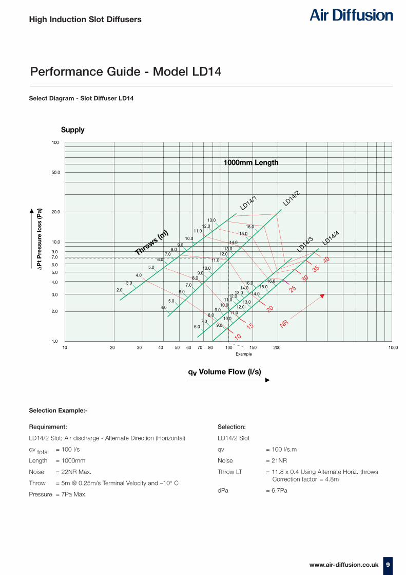
Select Diagram - Slot Diffuser LD14
Performance Guide - Model LD14
Requirement:
LD14/2 Slot; Air discharge - Alternate Direction (Horizontal)
qv total = 100 l/s
Length = 1000mm
Noise = 22NR Max.
Throw = 5m @ 0.25m/s Terminal Velocity and –10° C
Pressure = 7Pa Max.
Selection:
LD14/2 Slot
qv = 100 l/s.m
Noise = 21NR
Throw LT = 11.8 x 0.4 Using Alternate Horiz. throwsCorrection factor = 4.8m
dPa = 6.7Pa
Selection Example:-
10 www.air-diffusion.co.uk
High Induction Slot Diffusers
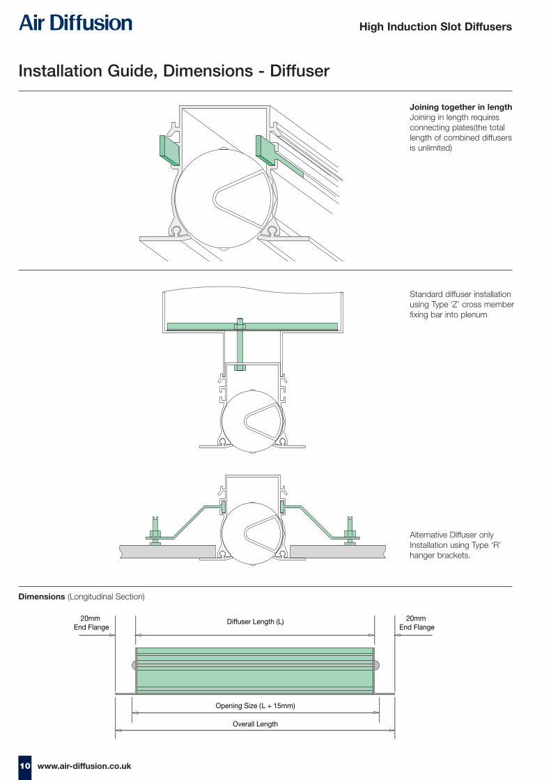
Installation Guide, Dimensions - Diffuser
Joining together in lengthJoining in length requiresconnecting plates(the totallength of combined diffusersis unlimited)
Standard diffuser installationusing Type ‘Z’ cross memberfixing bar into plenum
Alternative Diffuser onlyInstallation using Type ‘R’hanger brackets.
Diffuser Length (L)20mm End Flange
20mm End Flange
Opening Size (L + 15mm)
Overall Length
Dimensions (Longitudinal Section)

11www.air-diffusion.co.uk
High Induction Slot Diffusers
11
LD 13
A E F
1 Slot 33 57.5 24.4
2 Slot 67 92 58.2
3 Slot 101 126.5 92.0
4 Slot 135 161.5 125.8
Dimensions
F
9.4
8.5
41.5
15
A
E
Installation openings: (A + 5) x (L + 15)
8.5
53.5
F
9.4
26
A
E
Installation openings: (A + 5) x (L + 15)
www.air-diffusion.co.uk
57.5
92
126.5
161.5
LD 13
1 Slot
LD 13
2 Slot
LD 13
3 Slot
LD 13
4 Slot
69.5
115.5
162.5
208.5
LD 14
1 Slot
LD 14
2 Slot
LD 14
3 Slot
LD 14
4 Slot
41.5
53.5
53.5
53.5
53.5
41.5
41.5
41.5
LD-130 1 Slot
37.5
41.5
53.5
50
53.5
96.5
53.5
142
53.5
187.5
LD-130 2 Slot
41.5
72.5
LD-130 3 Slot
41.5
107
LD-130 4 Slot
LD-140 1 Slot
LD-140 2 Slot
LD-140 3 Slot
LD-140 4 Slot
41.5
142
LD 13 with Flange : Overall Flange Dimensions
LD 13/2 LD 14/2
LD 14 with Flange : Overall Flange Dimensions
LD 130 No Flange : Overall Flange Dimensions LD 140 No Flange : Overall Flange Dimensions
LD 14
A E F
1 Slot 44 69.5 35.3
2 Slot 89 115.5 80
3 Slot 133 162.5 124.7
4 Slot 178 208.5 169.4

12 www.air-diffusion.co.uk
High Induction Slot Diffusers
Ordering Information - Diffuser
Standard Anodised (1) Aluminium
Option White PPC RAL9010 (83) (20% gloss) with other
finishes also available on request (Options as additional cost items)
Black or White
(Black supplied asstandard if notconfirmed on order)
Style No. of Slots Ends Fixing Frame Finish Deflector Finish Type of Discharge Diffuser LengthLD13 2 E Z Standard (1) Black C 1500
Example
Important Note: If the overall size is critical then it must be clearly stated on the order.All orders must be addressed to AIR DIFFUSION, Ruskin Air Management Limited.
Style Slot Width
LD13 15mm slot 12mmflanged frame
LD 130 15mm slot 5mmflangeless frame
LD14 26mm slot 12mmflanged frame
LD140 26mm slot 5mmflangeless frame
1 – 1 slot
2 – 2 slot
3 – 3 slot
4 – 4 slot
a
b
c
d
e
f
g
E End flanges onboth ends
ET End flange onone end only
F End plate onboth ends
FT End plate onone end only
Note:‘F’ and ‘FT’only onLD130 and LD140
Z Standard - secretfixing with crossmember bracketsecured ontoplenum box
R Hanger Brackets
Note: Redesign may occurwhich supersedes theinformation in this brochure.
a b
Standard (left, right)
Standard (left, right)
c
Standard (left)
d
Standard (vertical)
fe g
Air jet angle 60° (right)
Air jet angle 60° (right)
Air jet angle 60° (left, right)
Type of Discharge Set Ups

13www.air-diffusion.co.uk
High Induction Slot Diffusers
Plenum Box Specification
Plenum Boxes
Supplied unlined as standard with side entryspigot.
Plenum boxes can be supplied internallylined with 12mm class “O” foam at extracost. Apply to sales office for price.
Specifications
MaterialStandard is a minimum of 0.7mm thickgalvanised or zinc coated steel.
ConstructionPlenum boxes are generally fabricated in3 sections having tray ends, which areeither mechanically joined or spot weldedto form an airtight seal. Flush ends (notray indents) are also available. Asstandard, spigots are side entry andlocated centrally. All boxes are suppliedwith plain edges, as standard, (F0 fixing).Equalising mesh grid fitted a standard.
Standard Installation MethodThe tray ends of the plenum boxincorporate a 15mm indent, on each sideto allow for 8mm drop rod fixings, whichgives space for holes to be drilled (byothers) without disturbing the activesection.
Installation OptionsFixing lugs can be factory fitted ifpreferred or special fixing methods (byothers) may be used.
For plenum boxes having flush endsseparate hanging brackets/fixing lugsneed to be fitted to allow independentsupport of diffuser and plenum box.
AccessoriesJoggled style plenum boxes or panadapters.
Spigot dampers include; cord operated orquadrant.
12mm thick Class ‘O’ internal lining.
Turning Vanes.
Fixing lugs or special fixings (by others).
Flush Ends (No Indent).
FinishSelf finish galvanised or zinc coated steelas standard.
Black paint can be applied to internalfaces if required.
Pressure Drops and Sound Rating
Spigot Velocity m/s
1.5 2.0 2.5 3.0 3.5 4.0
Pressure Drop Pa* 2 4 6 8 12 16
Sound Power Level NR* - - 25 30 35 40
* The figures given are approximate - dependent upon spigot entry conditions
Spigot Velocity m/s
Diameter (mm) 1.5 2.0 2.5 3.0 3.5 4.0
100 10 15 19 22 26 30
125 18 24 30 35 41 47
150 25 34 42 51 60 68
175 35 46 58 70 82 94
200 45 60 75 91 109 121
225 58 77 96 117 137 151
250 71 95 120 142 170 191
275 86 115 145 172 205 230
300 103 139 172 208 240 275
325 120 160 200 240 280 320
350 140 188 235 280 328 375
400 185 245 310 370 430 495
The pressure drop given is for supplygrille with damper fully open. When thegrille is installed with plenum box, the
pressure loss of the box has to be addedto the grille.
Plenum Box Spigot Volumes (l/s)
14 www.air-diffusion.co.uk
High Induction Slot Diffusers
65
W35 35
Equalising Mesh
(Optional)
L
L + 30
20
30
D
H
8mm hole for support rods
X
OVERALLPLENUM WIDTH
65
*
*
20
D
X
Allow ‘D’ when cord
operated damper fitted
Cord operated
spigot damper
(Optional)
Plenum box with cord
operated damper in spigot
O
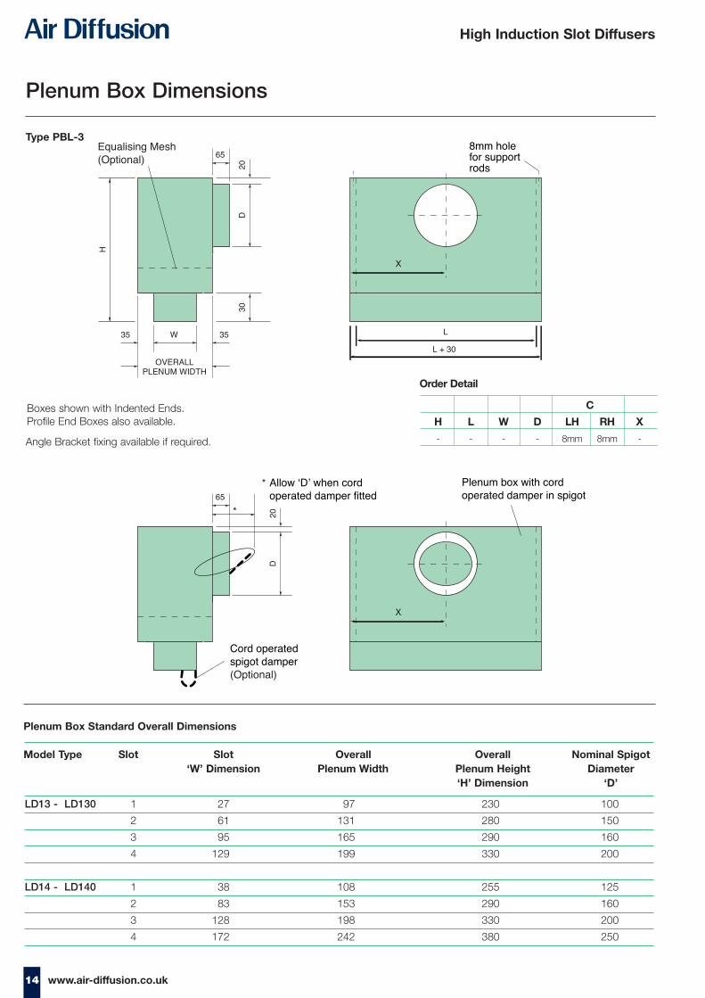
Type PBL-3
Plenum Box Standard Overall Dimensions
Boxes shown with Indented Ends. Profile End Boxes also available.
Angle Bracket fixing available if required.
C
H L W D LH RH X
- - - - 8mm 8mm -
Order Detail
Plenum Box Dimensions
LD13 - LD130 1 27 97 230 100
2 61 131 280 150
3 95 165 290 160
4 129 199 330 200
LD14 - LD140 1 38 108 255 125
2 83 153 290 160
3 128 198 330 200
4 172 242 380 250
Model Type Slot Slot Overall Overall Nominal Spigot‘W’ Dimension Plenum Width Plenum Height Diameter
‘H’ Dimension ‘D’
15www.air-diffusion.co.uk
High Induction Slot Diffusers
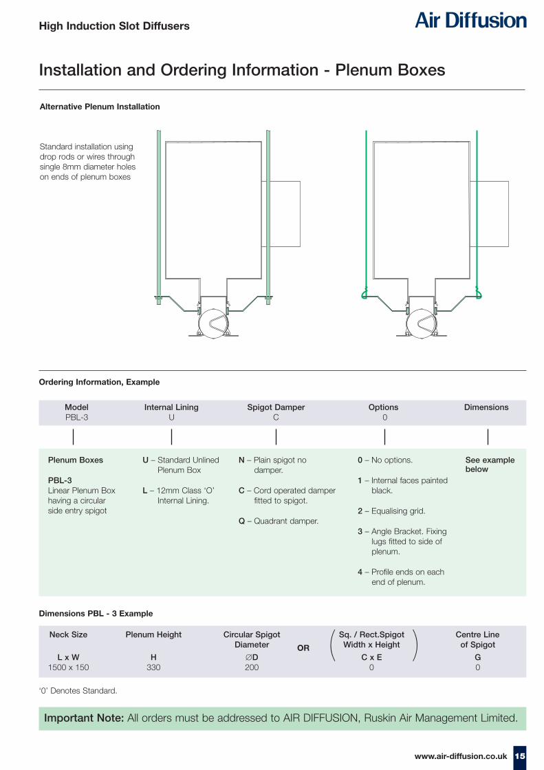
Standard installation usingdrop rods or wires throughsingle 8mm diameter holeson ends of plenum boxes
Alternative Plenum Installation
Installation and Ordering Information - Plenum Boxes
Important Note: All orders must be addressed to AIR DIFFUSION, Ruskin Air Management Limited.
Plenum Boxes
PBL-3Linear Plenum Boxhaving a circularside entry spigot
Model Internal Lining Spigot Damper Options DimensionsPBL-3 U C 0
Neck Size Plenum Height Circular Spigot Sq. / Rect.Spigot Centre Line Diameter Width x Height of Spigot
L x W H ∅D C x E G1500 x 150 330 200 0 0
Ordering Information, Example
Dimensions PBL - 3 Example
U – Standard UnlinedPlenum Box
L – 12mm Class ‘O’ Internal Lining.
N – Plain spigot no damper.
C – Cord operated damperfitted to spigot.
Q – Quadrant damper.
0 – No options.
1 – Internal faces painted black.
2 – Equalising grid.
3 – Angle Bracket. Fixing lugs fitted to side of plenum.
4 – Profile ends on each end of plenum.
See example below
OR ( )‘0’ Denotes Standard.

BROCHURE PRODUCTION
www.geoffstrange.co.uk
High Induction Slot Diffusers
Stourbridge Road, Bridgnorth, Shropshire,WV15 5BB England.Tel: 01746 761921 Fax: 01746 760127 Email: [email protected]: www.air-diffusion.co.uk
Ruskin Air Management Limited
Ruskin Air Management Limiteda BS EN ISO 9000 registered company
The statements made in this brochure or by ourrepresentatives in consequence of any enquiriesarising out of this document are given for informationpurposes only. They are not intended to have anylegal effect and the company is not to be regardedas bound thereby. The company will only acceptobligations which are expressly negotiated for andagreed and incorporated into a written agreementmade with its customers.
Due to a policy of continuous product developmentthe specification and details contained herein aresubject to alteration without prior notice.